Abstract
Heavy oil reservoirs are often characterized by high viscosity and poor mobility, which is more complex with the presence of bottom water. The conventional vertical well development method has low oil recovery efficiency and limited controlled reserves of a single well. In addition, water cut can increase dramatically when the edge-bottom water breaks through. Horizontal well and CO2 huff-n-puff is an effective alternative development model for heavy oil reservoirs. This development method makes efficient use of CO2 and accords with the “Carbon Capture, Utilization, and Storage (CCUS)”. The horizontal well can increase the drainage area. The dissolution of CO2 improves the mobility of crude oil and increases formation energy. In this paper, we established numerical simulation models based on the Liuguanzhuang oilfield in Dagang. The characteristics and producing rules of the horizontal well and CO2 huff-n-puff development in the heavy oil reservoir were studied. The results show that the production characteristics of horizontal well and CO2 huff-n-puff were similar to Steam-Assisted Gravity Drainage (SAGD). CO2 forms a viscosity reduction area above the horizontal well and the heavy oil flows into the wellbore due to gravity after viscosity reduction. The CO2 huff-n-puff can effectively enhance the production area of horizontal wells compared with the depletion development. However, the improvement in the production area gradually decreased as CO2 huff-n-puff cycles continued. There was a boundary of production area against the horizontal well, with the main production of heavy oil occurring at the upper and either end of the horizontal well. The CO2 huff-n-puff has a restraining effect on the edge-bottom water, which is confirmed via the proposed theoretical model.
1. Introduction
CO2 huff-n-puff is one of the main technologies for oilfield development, which is widely used in the development of low-permeability, tight-oil, and heavy-oil reservoirs. Moreover, it is the main applying direction in heavy oil stimulation. Ways to conduct effective carbon capture, utilization and storage (CCUS) have become a widely held concern among scholars in recent years [1,2,3,4,5,6,7,8,9]. Since CO2 has higher solubility in heavy oil than other gases, the stimulation mechanism of CO2 huff-n-puff is more prominent, which can control the production gas–oil ratio in a short period and significantly increase the cumulative oil production in heavy oil reservoirs [10,11,12,13]. The viscosity reduction effect of CO2 is remarkable, the applicable range of heavy oil properties is wide, and the viscosity reduction ratio can reach 99.8%. The crude oil expands and the expansion coefficient can reach 1.28. Both experimental studies and field tests show that CO2 huff-n-puff technology is one of the most successful EOR methods for heavy oil recovery [14,15,16,17,18].
Previous researchers carried out various studies on enhancing oil recovery using CO2 huff-n-puff technology in oilfields. In 1986, Haskin et al. [19] demonstrated the influence of CO2 injection volume and soaking time on crude oil production with different viscosities based on the CO2 huff-n-puff project in Texas. The higher the viscosity of crude oil, the larger the amount of CO2 injection required. In 1988, Monger et al. [20] studied the CO2 huff-n-puff effect of a light sandstone reservoir in southern Louisiana. The field test showed that the larger the reservoir volume swept using CO2, the lower the viscosity of reservoir crude oil. At the same time, CO2 injection can also inhibit water production in oil wells [21,22]. In 1994, Miller et al. [23] summarized the effect of CO2 huff-n-puff from 1984 to 1989 in the light oil reservoir of Big Sinking Oilfield in Kentucky. In 5 years, 1.22 × 10⁴ t CO2 gas was injected accumulatively, the number of huff-n-puff wellheads reached 290, the stimulation operation volume reached 390 times, and the final huff-n-puff oil increment was 1.8 × 10⁵ bbl. The study conducted by Wehner et al. [24] in 1996 showed that the CO2 huff-n-puff development technology has a high oil production rate, short production decline cycle, and high gas–oil ratio at the initial stage. When oil production reaches the peak, the water-oil ratio will not decrease anymore and gradually recover to the initial level. In 2012, Firouz A.Q. et al. [25] carried out a comparative experiment of methane solvent and methane–CO2 mixed solvent huff-n-puff in heavy oil reservoir and found that the recovery ratio of CO2 huff-n-puff was higher under the same conditions. When the pressure is low, the effect of heavy oil huff-n-puff with methane–CO2 mixed solvent is better than that with pure methane solvent. Supercritical CO2 has a good effect on reducing crude oil viscosity [26,27], and the viscosity reduction effect is far better than that of methane; thus, pure CO2 solvent heavy oil huff-n-puff has the best effect. The injected gas can form foam with crude oil under certain conditions, and the foam can improve the displacement efficiency of the reservoir and ultimately increase the oil recovery [28,29]. CO2 combined with foaming agents can enhance oil recovery through producing bubbles and reducing oil viscosity [30]. In addition to viscosity reduction and volume expansion of crude oil, CO2 injection can also reduce near-wellbore reservoir damage, which can enhance crude oil production [31,32,33]. Compared with conventional vertical well huff-n-puff development, horizontal wells increase the reservoir swept volume of CO2 and are more suitable for continuous heavy oil reservoirs [34,35,36]. Compared with vertical well development, bottom water breakthrough can change water coning to water line advancement, and the overall pressure distribution of bottom water is relatively stable and easier to control. Horizontal well and CO2 huff-n-puff development are more beneficial in inhibiting bottom water coning [37,38,39,40].
This paper established a conceptual model of the horizontal well and CO2 huff-n-puff based on the Liuguanzhuang Oilfield in Dagang. The study aims to analyze the production behavior of horizontal wells through reservoir numerical simulation. The paper also examines the impact of crude oil viscosity and reservoir permeability on the efficiency of CO2 huff-n-puff, while the production behavior of different huff-n-puff cycles was analyzed. Moreover, we present a case analysis of a typical heavy oil reservoir in Liuguanzhuang and verify the conclusions of numerical simulation research. The study deepens the accuracy of understanding the production law and provides a theoretical basis and reference for the field development of horizontal well and CO2 huff-n-puff.
2. Overview of the Study Area
There are many oil-bearing formations in the Liuguanzhuang oilfield; the depth of the reservoir is 1300~2200 m. There are high-quality oil and gas reserves located between the Ming and Sha layers. Figure 1 shows the characteristics of the complex reservoirs, which include structure and lithology. The reservoirs are mainly controlled via structures and have uniform oil–water contact. The oil and gas accumulate in the high part of the reservoir and are controlled through the distribution of sand bodies.
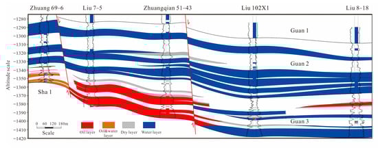
Figure 1.
Reservoir profile of Liuguanzhuang oilfield.
Liuguanzhuang oilfield is characterized by late accumulation. The reservoirs are generally oxidized via water washing. According to the statistics regarding the crude oil properties of each layer series, the density of crude oil at 20 °C is between 0.92 and 0.95 g/cm3, and the viscosity of degassed crude oil at 50 °C is between 100 and 10,000 mPa·s. The overall performance is that the crude oil properties of the Guan and Ming layers are characterized by high crude oil density, high crude oil viscosity, high asphaltene content, low freezing point, low wax content, and low sulfur content, with these properties belonging to heavy oil. The study area of this paper is mainly located in the Guan layer.
3. Study on the Producing Law of CO2 Huff-n-Puff
3.1. Numerical Model Parameter Setting
The mechanism model of the horizontal well and CO2 huff-n-puff was based on the Guan layer in the Liuguanzhuang reservoir through applying Eclipse and tNavigator simulators. The compositional model was established with the PVT properties of the crude oil. The components and mole fraction of crude oil are shown in Table 1. Figure 2 shows the relative permeability function curve in the numerical simulation. The conceptual model establishment schematic diagram is shown in Figure 3.

Table 1.
Crude oil component division data sheet.
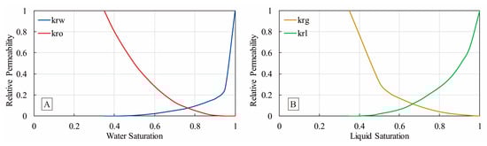
Figure 2.
Relative permeability function curve: (A) oil–water relative permeability; (B) gas–liquid relative permeability.
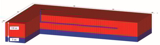
Figure 3.
Schematic diagram of horizontal well mechanism model.
The horizontal section of the horizontal well is located in the middle of the reservoir grids, and the length of the horizontal section is 200 m, according to the horizontal well parameters of the actual block. The horizontal section is fully perforated. The development mode is CO2 huff-n-puff development, and the huff-n-puff cycles are five times. In each cycle round, CO2 injection lasts for 20 days, well soaking lasts for 15 days, and well production lasts for 60 days. The daily gas injection volume is 15,000 m3/day. Table 2 shows the basic parameters of the model. Through the reservoir conceptual model, the study on pressure diffusion of well soaking, oil viscosity, saturation change after different cycles of development, and production area of the horizontal well is carried out.
Table 2.
Parameters of conceptual model of horizontal well huff-n-puff technology policy.
3.2. Pressure Diffusion Law of Soaking the Well
Figure 4 shows the average reservoir pressure change curve during five cycles of CO2 huff-n-puff production. With the development of the simulation, the reservoir pressure decreases from 13 to about 7 MPa. The gas injection stage can make the pressure of the whole area rise again, but the overall trend is downward. The gas injection stage can increase the average pressure of the whole area by 3~4 MPa. The pressure increases by about 3 MPa in each huff-n-puff cycle. In the subsequent cycles, the minimum pressure of the whole area retains about 7 MPa and does not decrease significantly, which shows CO2 huff-n-puff can supplement and maintain certain reservoir energy.
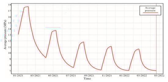
Figure 4.
Average pressure change curve of reservoir.
Figure 5 compares the pressure distribution histogram of the numerical model grid at the end of gas injection and well soaking. During the 15-day well soaking process, there is an obvious process of outward pressure diffusion. The pressure is gradually swept outward from the near horizontal well area. The pressure of the whole area changes from 13~21 to 16~18 MPa. At the end of the well soaking stage, the overall pressure distribution of the whole area is more uniform, though there is a certain pressure-swept boundary.
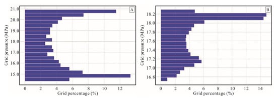
Figure 5.
Model grid pressure distribution histogram: (A) completion of 1st cycle of gas injection; (B) completion of 1st cycle of soaking.
3.3. Production area of Horizontal Well
Figure 6 shows the variation in the remaining oil saturation and crude oil viscosity in different huff-n-puff cycles. With the increase in huff-n-puff cycles, the production area of the horizontal well expands continuously, and the area with low crude oil saturation and viscosity increases. However, compared to the third and fifth cycles, it can be seen that the increasing range of production area becomes smaller. The increasing rate of production area is gradually decreased as CO2 huff-n-puff cycles continue, and there is a boundary in the production area of a single-well huff-n-puff. From Figure 5, the overall production area at both ends (heel and toe) of horizontal wells is larger, the producing distance outward is farther, and the grid range of low crude oil saturation and low viscosity is expanded outwardly.
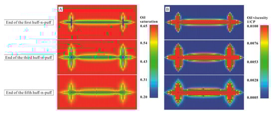
Figure 6.
Remaining oil saturation and crude oil viscosity field: (A) remaining oil saturation change; (B) viscosity change in crude oil.
Figure 7 shows the distribution of remaining oil saturation of the reservoir after five cycles of CO2 huff-n-puff development, including the top view A and the cross sections in three different directions of B, C, and D. From section A, after five cycles of huff-n-puff, both ends of the horizontal well are the main production areas, while the middle part is seldom exploited. Section B shows there is more oil produced from the upper area than the lower area, and most crude oil is produced in the area right above the horizontal well with many blue grids. The production areas of the heel and toe of the horizontal well are larger than those of the middle section of the horizontal well; however, the overall saturation color above the middle section of the horizontal well is bluer, and the crude oil recovery degree within the range of huff-n-puff is larger. Section C is the section at both ends (heel and toe) of the horizontal well, and section D is the section at the middle section of the horizontal well. Compared with sections C and D, both ends of the horizontal well have a larger production area. With the increase in huff-n-puff development cycles, the crude oil saturation decreases ever-more obviously. The main oil recovery comes from the area above the horizontal well.
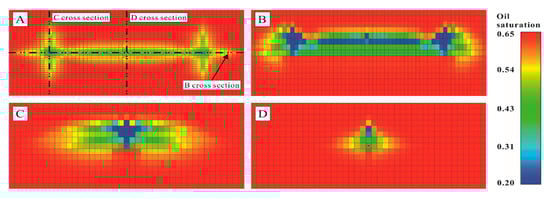
Figure 7.
Schematic diagram of oil saturation in production area of horizontal well at end of five cycles of CO2 huff-n-puff: (A) top view; (B) parallel horizontal well section; (C) vertical sections at heel of horizontal well; (D) vertical section in middle of horizontal well.
This producing character of the heavy oil reservoir is related to oil viscosity and the development mode of CO2 huff-n-puff. Due to the high viscosity of heavy oil, similar to SAGD (steam-assisted gravity drainage) development, the production of heavy oil mainly depends on the physical (temperature rise) and chemical (viscosity reduction) effects of injected agents to reduce viscosity of crude oil and enhance mobility, allowing oil to flow into the wellbore due to gravity. The injected CO2 mainly moves to the reservoir above the horizontal well, mixes with the crude oil, and dissolves, forming a gas cavity viscosity reduction area with an elliptical section above the horizontal well. In the production stage, the crude oil after viscosity reduction flows into the horizontal wellbore due to gravity; thus, the crude oil-producing degree in this area is the highest.
Figure 8 shows the streamline model of the horizontal well in the production stage. The streamlines at both ends of the horizontal well are denser than those in the middle area (under the same perforation density). From Figure 8A, the perforation point in the middle of the horizontal well has two parallel boundaries, while, at both ends, the perforation points can be regarded as hemispherical boundaries, and the streamline swept volume is larger. From Figure 8B, the upper streamline of the horizontal well is dense and the lower part is sparse, indicating that after multiple cycles of huff-n-puff, the upper-located crude oil easily flows into the wellbore due to gravity, and the lower-located crude oil is less effectively produced.
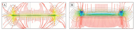
Figure 8.
Streamline of horizontal well for CO2 huff-n-puff: (A) top view; (B) parallel horizontal well section.
4. Analysis of Influence Factors of CO2 Huff-n-Puff Development
4.1. Effects of Different Crude Oil Viscosity
Figure 9 shows the remaining oil saturation distribution of the reservoir after five cycles of CO2 huff-n-puff under different crude oil viscosities. Under the same permeability condition (set to 1000 mD), the horizontal well mechanism models with different crude oil viscosities (50 mPa·s, 800 mPa·s, 2000 mPa·s, 3200 mPa·s) were built.
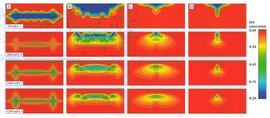
Figure 9.
Schematic diagram of oil saturation change in different crude oil viscosities affecting production area of horizontal wells: (A) top view; (B) parallel horizontal well section; (C) vertical sections at heel of horizontal well; (D) vertical section in middle of horizontal well.
Under the condition of low crude oil viscosity, the injected CO2 flows upward to the top of the reservoir (Figure 9B), and the crude oil at the upper part of the horizontal well will be continuously produced as the huff-n-puff cycles continue. Since most of the gas flows upward, the crude oil at the lower part is less effectively produced. As the crude oil viscosity increases, the mobility ratio of gas and crude oil increases; less CO2 flows to the top of the reservoir, being dissolved into the high-viscosity crude oil; and the injected gas flows horizontally to increase areal conformance (Figure 9C,D). Thus, the production area of the horizontal well decreases in the vertical direction and increases in the lateral direction. With the increase in crude oil viscosity, the overall production area of horizontal wells shows a decreasing trend.
4.2. Effects of Different Crude Oil Viscosity
Figure 10 shows the remaining oil saturation distribution after five cycles of CO2 huff-n-puff under different reservoir permeabilities. With the same crude oil viscosity (2000 mPa·s), horizontal well mechanism models with different permeabilities (50 mD, 300 mD, 1000 mD, 2000 mD) were built.
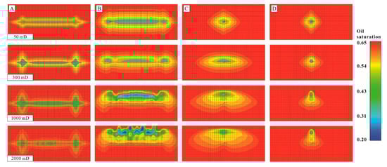
Figure 10.
Oil saturation change diagram of influence of different reservoir permeability on production area of horizontal wells: (A) top view; (B) parallel horizontal well section; (C) vertical sections at heel of horizontal well; (D) vertical section in the middle of horizontal well.
In the case of low permeability, the mobility of heavy oil is rather small, as gravity cannot displace the heavy oil sufficiently. Moreover, due to the limited upward diffusion of gas, the downward flow of heavy oil is not obvious due to gravity, indicating that low permeability limits gravity and the shape of the vertical and horizontal production area of the horizontal well is relatively regular (Figure 10C,D). With the increase in permeability, the injected CO2 obtains a longer flowing distance in both vertical and horizontal directions (Figure 10B,C); the production area of the horizontal well becomes wider in all directions; and the upward expansion is more obvious, which results from upward diffusion of CO2. Meanwhile, the gravity drainage effect becomes more obvious, which makes the oil recovery in the upper part of the horizontal well higher and the production effect remarkable.
4.3. Effects of Bottom Water
No matter if a vertical or horizontal well is being studied, bottom water coning occurs, which causes the water cut to rise. It is difficult to control EOR of heavy oil reservoirs with bottom water. Water coning can form dominant channels in developing progress.
Under the condition of bottom water, several conceptual models with different crude oil viscosities were built (Figure 11). When the oil viscosity is low, the bottom water breakthrough occurs more easily, and the oil saturation in the middle of the horizontal well decreases more rapidly. When oil viscosity is high, the dominant flowing channel of bottom water gathers to the toe and heel of the horizontal well, and the flow density at both ends of the horizontal well is larger. With the increase in crude oil viscosity, this phenomenon is more obvious.
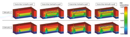
Figure 11.
Remaining oil saturation field of conceptual models of heavy oil reservoir with different crude oil viscosities and bottom water (profile).
Figure 12 shows the water saturation distribution at the end of the last cycle of production and after the next cycle of gas injection via CO2 huff-n-puff. As shown in Figure 12, the water saturation at the bottom of the horizontal well decreases obviously after gas injection, indicating that CO2 injection has a certain effect of inhibiting bottom water. However, within the production cycle, it be cannot maintained for a long time, which is mainly due to two reasons: (1) with the development of horizontal wells, there is a dominant flowing channel for the formation water below the horizontal wells; and (2) the main production position of the horizontal well in heavy oil reservoirs is located near the heel and toe of the horizontal well. The injected CO2 is partially dissolved in the crude oil of lower formation, which increases the mobility of crude oil and makes the bottom water flow into the wellbore more easily.
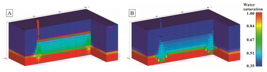
Figure 12.
Water saturation field (profile): (A) end of production stage; (B) end of gas injection stage.
5. Oilfield Case Study and Discussion
Figure 13 displays the actual model of Guan 3–4 layers in the Liuguanzhuang oilfield. The initial oil saturation of Guan 3-4 layers is 0.65, and the crude oil viscosity is 2300 mPa·s. This reservoir with edge-bottom water is mainly controlled via faults and sand bodies, while the oil-bearing layer is relatively thick. The reservoir is primarily made of movable water; the geological reserves are relatively large, accounting for more than half of the overall geological reserves of the third fault block, and are the main development layer series of the third fault block.
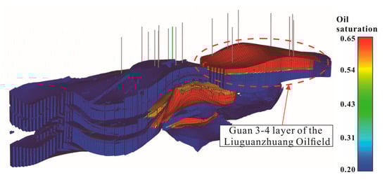
Figure 13.
Actual model of Guan 3-4 layer in Liuguanzhuang oilfield.
There are 14 production wells, 3 water injection wells, and 2 CO2 huff-n-puff horizontal wells in the actual model. From March 2015 to June 2021, we simulated the development of Guan 3-4 layers in the Liuguanzhuang oilfield. Figure 14 displays the historical matching result curve of the whole area, which shows that the overall matching is satisfactory.
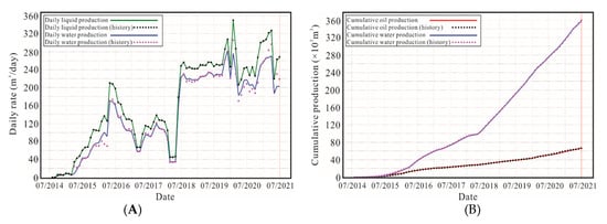
Figure 14.
Historical matching result curve: (A) daily fluid production and daily water production fitting curve; (B) cumulative oil production and cumulative water production fitting curve.
Figure 15 shows the production performance curve of the Liu 5–14H wells. After a period of depletion development, the well is converted into a CO2 huff-n-puff well. There is a sudden increase in water production, which indicates that bottom water breakthrough occurs, resulting in an increase in water cut. After the first cycle of gas injection, the oil production increases to 12 m3/day at the maximum, and the water production decreases at the initial stage of well production, indicating that CO2 injection has an obvious effect on inhibiting bottom water at the initial stage; however, the water cut increases rapidly at the later stage, indicating that the decrease in crude oil viscosity enhances the mobility of reservoir fluids and makes it easier for bottom water to flow into the wellbore.
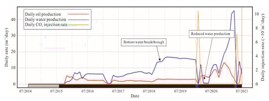
Figure 15.
Liu 5-14H production performance curve.
Figure 16 is the reservoir profile of Guan 3-4 layers in the Liuguanzhuang oilfield. Liu 5-14H, Liu 5-10H, and Liu 5-8H in the profile are all horizontal wells, among which Liu 5-14H is a huff-n-puff well. The CO2 huff-n-puff production characteristics and rules of heavy oil reservoirs with bottom water are as follows:
- (1)
- The huff-n-puff CO2 is enriched in the upper part of the horizontal well, unlocking the upper crude oil, and the oil recovery is high;
- (2)
- All horizontal wells have different degrees of bottom water coning, producing lower crude oil;
- (3)
- The horizontal well mainly produces crude oil in the heel and toe areas, and the production area around the middle of the horizontal well is smaller. The producing radius of the horizontal well in depletion development is about 30 m, and the radius of the production area can be expanded to about 60 m in huff-n-puff development.

Figure 16.
Reservoir profile of actual model of Guan-3-4 in the Liuguanzhuang oilfield.
To improve the crude oil recovery, it is suitable to arrange horizontal wells in this area to adopt CO2 huff-n-puff development; however, the horizontal wells should be arranged as far away from bottom water as possible and close to the middle and upper parts of the reservoir, and the well production cycles of CO2 huff-n-puff development should be reasonable, which can effectively prevent bottom water breakthrough. From the simulation results of the actual model, the overall production law of horizontal well huff-n-puff development in the heavy oil reservoir with bottom water conforms to the mechanism model.
6. Conclusions
The research has the following conclusions:
- (1)
- Horizontal well and CO2 huff-n-puff development can supplement and maintain certain reservoir energy. There is a pressure diffusion process during the soaking stage, in which the pressure is gradually spread outward from the near horizontal area, making the overall pressure distribution in the whole area more uniform at the end of the soaking stage; however, the pressure spread has a certain boundary.
- (2)
- With the increase in huff-n-puff cycles, the overall production area of horizontal wells increases outwardly, and the area with low oil saturation and viscosity increases. However, when the number of huff-n-puff cycles increases to a certain extent, the production area of horizontal wells will not continue to increase significantly, and there is a boundary in the production area of a single well huff-n-puff. The production area of the heel and toe end is larger than that of the middle part of the horizontal well. The CO2 huff-n-puff law of horizontal wells is similar to that of SAGD development.
- (3)
- With the increase in reservoir crude oil viscosity, the upper production area of the horizontal well will be ever-smaller, the lateral production area will increase, and the overall production area of the horizontal well will decrease. The lower the reservoir permeability, the smaller the gravity effect and the production area of the horizontal well. With the increase in permeability, the production area of the horizontal well will expand vertically and laterally, with the vertical expansion being the most obvious outcome.
- (4)
- For heavy oil reservoirs with bottom water, CO2 huff-n-puff can restrain bottom water; however, as water coning is the dominant flowing channel of formation water, the gas injection can only restrain bottom water breakthrough at the initial production stage. The enhancement of crude oil mobility further increases the water production of bottom water breakthrough; thus, it is necessary to design a reasonable huff-n-puff production system.
Author Contributions
Conceptualization, P.L. and Z.X.; methodology, Z.X., L.Z. and S.M.; software, Z.X. and J.Q.; validation, X.H. and B.H.; resources, Y.L.; writing—original draft preparation, Z.X.; writing—review and editing, P.L. and L.Y.; supervision, L.Z. All authors have read and agreed to the published version of the manuscript.
Funding
This research was funded by the National Natural Science Foundation of China (51774256).
Data Availability Statement
Not applicable.
Acknowledgments
The authors would like to thank the research team members for their contributions to this work.
Conflicts of Interest
The authors declare no conflict of interest.
References
- Ren, B.; Male, F.; Duncan, I.J. Economic analysis of CCUS: Accelerated development for CO2 EOR and storage in residual oil zones under the context of 45Q tax credit. Appl. Energ. 2022, 321, 119393. [Google Scholar] [CrossRef]
- Shiyi, Y.; Desheng, M.; Junshi, L.; Tiyao, Z.; Zemin, J.; Haishui, H. Progress and prospects of carbon dioxide capture, EOR-utilization and storage industrialization. Petrol. Explor. Dev. 2022, 49, 955–962. [Google Scholar] [CrossRef]
- Tian, C.; Pang, Z.; Liu, D.; Wang, X.; Hong, Q.; Chen, J.; Zhang, Y.; Wang, H. Micro-action mechanism and macro-prediction analysis in the process of CO2 huff-n-puff in ultra-heavy oil reservoirs. J. Pet. Sci. Eng. 2022, 211, 110171. [Google Scholar] [CrossRef]
- Li, B.; Zhang, Q.; Li, S.; Li, Z. Enhanced heavy oil recovery via surfactant-assisted CO2 huff-n-puff processes. J. Pet. Sci. Eng. 2017, 159, 25–34. [Google Scholar] [CrossRef]
- Liu, J.; Li, H.; Tan, Q.; Liu, S.; Zhao, H.; Wang, Z. Quantitative study of CO2 huff-n-puff enhanced oil recovery in tight formation using online NMR technology. J. Pet. Sci. Eng. 2022, 216, 110688. [Google Scholar] [CrossRef]
- Huang, X.; Wang, X.; He, M.; Zhang, Y.; Su, Z.; Li, X.; Yang, W.; Lu, J. The influence of CO2 huff and puff in tight oil reservoirs on pore structure characteristics and oil production from the microscopic scale. Fuel 2023, 335, 127000. [Google Scholar] [CrossRef]
- Lei, Z.; Liu, Y.; Wang, R.; Li, L.; Liu, Y.; Zhang, Y. A Microfluidic Experiment on CO2 Injection for Enhanced Oil Recovery in a Shale Oil Reservoir with High Temperature and Pressure. Energies 2022, 15, 9461. [Google Scholar] [CrossRef]
- Ampomah, W.; Balch, R.S.; Grigg, R.B.; Cather, M.; Will, R.A.; Lee, S.Y. Optimization of CO2-EOR Process in Partially Depleted Oil Reservoirs. In Proceedings of the SPE Western Regional Meeting, Anchorage, AK, USA, 23–26 May 2016. [Google Scholar] [CrossRef]
- Ilyushin, Y.V.; Fetisov, V. Experience of virtual commissioning of a process control system for the production of high-paraffin oil. Sci. Rep. 2022, 12, 18415. [Google Scholar] [CrossRef]
- Li, S.; Zhang, S.; Zou, Y.; Zhang, X.; Liu, C. Experimental study on the feasibility of supercritical CO2-gel fracturing for stimulating shale oil reservoirs. Eng. Fract. Mech. 2020, 238, 107276. [Google Scholar] [CrossRef]
- Makimura, D.; Kunieda, M.; Liang, Y.; Matsuoka, T.; Takahashi, S.; Okabe, H. Application of molecular simulations to CO2-enhanced oil recovery: Phase equilibria and interfacial phenomena. SPE J. 2013, 18, 319–330. [Google Scholar] [CrossRef]
- Sayegh, S.G.; Maini, B.B. Laboratory evaluation of the CO2 huff-n-puff process for heavy oil reservoirs. J. Can. Pet. Technol. 1984, 23, PETSOC-84-03-02. [Google Scholar] [CrossRef]
- Shedid, S.A.; Zekri, A.Y.; Almehaideb, R.A. Optimization of carbon dioxide flooding for a middle-eastern heterogeneous oil reservoir. In Proceedings of the Canadian International Petroleum Conference, Calgary, AB, Canada, 17–19 June 2008. [Google Scholar] [CrossRef]
- Zhou, X.; Yuan, Q.; Peng, X.; Zeng, F.; Zhang, L. A critical review of the CO2 huff ‘n’ puff process for enhanced heavy oil recovery. Fuel 2018, 215, 813–824. [Google Scholar] [CrossRef]
- Zhou, X.; Yuan, Q.; Rui, Z.; Wang, H.; Feng, J.; Zhang, L.; Zeng, F. Feasibility study of CO2 huff ‘n’ puff process to enhance heavy oil recovery via long core experiments. Appl. Energ. 2019, 236, 526–539. [Google Scholar] [CrossRef]
- Zhou, X.; Li, X.; Shen, D.; Shi, L.; Zhang, Z.; Sun, X.; Jiang, Q. CO2 huff-n-puff process to enhance heavy oil recovery and CO2 storage: An integration study. Energy 2022, 239, 122003. [Google Scholar] [CrossRef]
- Sun, S.; Wu, Y.; Ma, X.; Liu, P.; Zhang, F.; Liu, P.; Zhang, X. Feasibility and Mechanism of Deep Heavy Oil Recovery by CO2-Energized Fracturing Following N2 Stimulation. Energies 2023, 16, 1161. [Google Scholar] [CrossRef]
- Shilov, E.; Cheremisin, A.; Maksakov, K.; Kharlanov, S. Huff-n-puff experimental studies of CO2 with heavy oil. Energies 2019, 12, 4308. [Google Scholar] [CrossRef]
- Haskin, H.K.; Alston, R.B. An evaluation of CO2 Huff ‘n’ Puff field tests in Texas. J. Pet. Technol. 1989, 41, 177–184. [Google Scholar] [CrossRef]
- Monger, T.G.; Coma, J.M. A laboratory and field evaluation of the CO2 huff ’n’ puff process for light-oil recovery. SPE Reserv. Eng. 1988, 3, 1168–1176. [Google Scholar] [CrossRef]
- Sankur, V.; Emanuel, A.S. A laboratory study of heavy oil recovery with CO2 injection. In Proceedings of the SPE California Regional Meeting, Ventura, CA, USA, 23–25 March 1983. [Google Scholar] [CrossRef]
- Palmer, F.S.; Landry, R.W.; Bou-Mikael, S. Design and implementation of immiscible carbon dioxide displacement projects (CO2 huff-puff) in South Louisiana. In Proceedings of the SPE Annual Technical Conference and Exhibition, New Orleans, LA, USA, 5–8 October 1986. [Google Scholar] [CrossRef]
- Miller, B.J.; Bardon, C.P.; Corlay, P. CO2 huff ‘n’ puff field case: Five-year program update. In Proceedings of the Permian Basin Oil and Gas Recovery Conference, Midland, TX, USA, 16–18 March 1994. [Google Scholar] [CrossRef]
- Wehner, S.C.; Prieditis, J. CO2 Huff-n-Puff: Initial Results from a Waterflood SSC Reservoir. In Proceedings of the Permian Basin Oil and Gas Recovery Conference, Midland, TX, USA, 27–29 March 1996. [Google Scholar] [CrossRef]
- Firouz, Q.; Torabi, F. Feasibility study of solvent-based huff-n-puff method (cyclic solvent injection) to enhance heavy oil recovery. In Proceedings of the SPE Heavy Oil Conference Canada, Calgary, AB, Canada, 12–14 June 2012. [Google Scholar] [CrossRef]
- Rahman, T.; Lebedev, M.; Barifcani, A.; Iglauer, S. Residual trapping of supercritical CO2 in oil-wet sandstone. J. Colloid Interf. Sci. 2016, 469, 63–68. [Google Scholar] [CrossRef]
- Li, S.; Li, Z.; Dong, Q. Diffusion coefficients of supercritical CO2 in oil-saturated cores under low permeability reservoir conditions. J. CO2 Util. 2016, 14, 47–60. [Google Scholar] [CrossRef]
- Aarra, M.G.; Skauge, A.; Solbakken, J.; Ormehaug, P.A. Properties of N2-and CO2-foams as a function of pressure. J. Pet. Sci. Eng. 2014, 116, 72–80. [Google Scholar] [CrossRef]
- Wu, Z.; Liu, H.; Pang, Z.; Wu, C.; Gao, M. Pore-scale experiment on blocking characteristics and EOR mechanisms of nitrogen foam for heavy oil: A 2D visualized study. Energy Fuels 2016, 30, 9106–9113. [Google Scholar] [CrossRef]
- Wu, Z.; Huiqing, L.; Wang, X.; Zhang, Z. Emulsification and improved oil recovery with viscosity reducer during steam injection process for heavy oil. J. Ind. Eng. Chem. 2018, 61, 348–355. [Google Scholar] [CrossRef]
- Alfarge, D.; Wei, M.; Bai, B.; Almansour, A. Effect of molecular-diffusion mechanisim on CO2 huff-n-puff process in shale-oil reservoirs. In Proceedings of the SPE Kingdom of Saudi Arabia Annual Technical Symposium and Exhibition, Dammam, Saudi Arabia, 24–27 April 2017. [Google Scholar] [CrossRef]
- Jin, L.; Sorensen, J.A.; Hawthorne, S.B.; Smith, S.A.; Bosshart, N.W.; Burton Kelly, M.E.; Miller, D.J.; Grabanski, C.B.; Harju, J.A. Improving oil transportability using CO2 in the Bakken System—A laboratorial investigation. In Proceedings of the SPE International Conference and Exhibition on Formation Damage Control, Lafayette, LA, USA, 24–26 February 2016. [Google Scholar] [CrossRef]
- Cui, G.; Yang, L.; Fang, J.; Qiu, Z.; Wang, Y.; Ren, S. Geochemical reactions and their influence on petrophysical properties of ultra-low permeability oil reservoirs during water and CO2 flooding. J. Pet. Sci. Eng. 2021, 203, 108672. [Google Scholar] [CrossRef]
- Yoosook, H.; Maneeintr, K.; Boonpramote, T. CO2 utilization for enhance oil recovery with huff-n-puff process in depleting heterogeneous reservoir. Energ. Proced. 2017, 141, 184–188. [Google Scholar] [CrossRef]
- Aakre, H.; Mathiesen, V.; Moldestad, B. Performance of CO2 flooding in a heterogeneous oil reservoir using autonomous inflow control. J. Pet. Sci. Eng. 2018, 167, 654–663. [Google Scholar] [CrossRef]
- Jafari, A.; Bachu, S. Evaluation of CO2 storage capacity in Devonian hydrocarbon reservoirs for emissions from oil sands operations in the Athabasca area, Canada. Energ. Proced. 2014, 63, 5222–5230. [Google Scholar] [CrossRef]
- Zhang, L.; Liao, H.; Cui, M. Effect of CO2 flooding in an oil reservoir with strong bottom-water drive in the Tahe Oilfield, Tarim Basin, Northwest China. Energ. Geosci. 2022, 100127. [Google Scholar] [CrossRef]
- Wang, C.; Wang, W.; Su, Y.; Zhao, Y.; Wen, J.; Li, L.; Hao, Y. Assessment of CO2 storage potential in high water-cut fractured volcanic gas reservoirs—Case study of China’s SN gas field. Fuel 2023, 335, 126999. [Google Scholar] [CrossRef]
- Wang, R.; Zhang, Y.; Lyu, C.; Lun, Z.; Cui, M.; Lang, D. Displacement characteristics of CO2 flooding in extra-high water-cut reservoirs. Energ. Geosci. 2022, 100115. [Google Scholar] [CrossRef]
- Sun, Y.Y.; Zhang, S.Y.; Yang, Z.P.; Sang, G.Q.; Li, T.; Li, Y.C. Laboratory simulation and CO2 flooding efficiency of oil-water transition zones in a low permeability reservoir in the Jilin Oilfield. Pet. Res. 2018, 3, 283–287. [Google Scholar] [CrossRef]
Disclaimer/Publisher’s Note: The statements, opinions and data contained in all publications are solely those of the individual author(s) and contributor(s) and not of MDPI and/or the editor(s). MDPI and/or the editor(s) disclaim responsibility for any injury to people or property resulting from any ideas, methods, instructions or products referred to in the content. |
© 2023 by the authors. Licensee MDPI, Basel, Switzerland. This article is an open access article distributed under the terms and conditions of the Creative Commons Attribution (CC BY) license (https://creativecommons.org/licenses/by/4.0/).