Abstract
Both direct and indirect heating compression methods were proposed to satisfy the requirement of industrial steam compression and supply. The compression process in a single-screw compressor was analyzed with the determination of different inlet and outlet boundary conditions. Considering the misalignment of meshing pairs caused by the offset of the star wheel axis and screw origin, the differential expansion of the vertical meshing pair was further analyzed. The inner ring of the sealing end face, the wall of the inner ring of the bearing at the inlet and outlet ends, and the bottom surface of the bracket were analyzed by different coordinate systems and different constraints, thus facilitating the design and selection of the single screw. The critical point for the design of a steam-type single-screw compressor is an outlet temperature of 350 °C and an outlet volume flow rate of 130 m3/min. At a flow rate of 130 m3/min, when the temperature exceeds 350 °C, the reliability of the compressor is still limited, and the differential expansion of the meshing pair exceeds 0.3 mm. In addition, superheating of steam can be improved by applying a centrifugal compressor with cascade compression and centrifugal compression in conjunction with reflux adjustment at the compression outlet.
1. Introduction
The development of renewable energy poses increasingly severe challenges to thermal power units that must undertake peak regulation and heat supply simultaneously [1]. As conventional steam supply methods, both direct temperature/pressure reduction measures and steam pressure matching modes have their own limitations. Hence, a steam supply method for heating units that uses a steam compressor has been proposed. Although this technical route has not been applied in peak regulation of thermal power units, there have been related studies on aerodynamics and the structure of the steam compression process [2,3]. Some studies about the application of steam compressors in quality improvements related to exhausted steam, as well as the related steam pipe network design, have also been conducted [4,5,6]. In order to adapt to the requirement of energy transformation, it is necessary to further tap the application potential of steam compressors in peak regulation of thermal power units and industrial steam supply.
The steam compressor was proposed by Leblanc. It was then introduced to air conditioning systems by Belmont in 1934 [7] and has been widely applied in the food and chemical industry [8]. The compression processes between water vapor and air are different since air can be considered as an ideal gas, while water vapor should be analyzed as an actual gas. Compression of the actual gas involves variable processes, and its thermodynamic process is more complex than that of ideal gas. Steam compression technology includes thermal steam compression and mechanical steam compression. The thermal compressor is a kind of gas transmission equipment that converts the kinetic energy of the mixture into gas pressure energy in the diffuser. This compressor has a simple structure. Since it has certain requirements for the pressure of driving steam, the thermal compressor is more suitable for stable working conditions, while the performance under varying operating conditions is poor.
Mechanical steam compression involves several methods, such as centrifugal-type, roots-type, and screw-type compression. There are also reciprocating compressors and axial-flow compressors, which are rarely used due to high cost and low applicability. Centrifugal steam compressors can adapt to large volume flow and have good vibration and balance performance, especially in applications of MVR (Mechanical Vapor Recompression). However, the pressure ratio of centrifugal compressors is small, which cannot meet the requirements of a high pressure ratio. Specifically, the saturation temperature rise of the centrifugal compressor is generally about 10 °C, and the pressure ratio is not higher than 2.0. In terms of a high-speed single-stage centrifuge with a speed box, the pressure ratio can increase to about 2.5 [9]. However, increasing speed or increasing the number of compression stages correspondingly increases the system cost and restricts economic viability. Meanwhile, if the working medium contains water droplets, the blades are prone to corrosion. The capacity of the existing centrifugal steam compressor covers the range of 4.5 t/h to 202 t/h, and the maximum temperature rise reaches 25 °C [9].
Roots steam compressors have a smaller volume flow and pressure ratio than centrifugal steam compressors. In addition, roots steam compressors have problems related to low efficiency, high noise, and poor regulation performance. Thus, it is generally applicable to small systems with a stable flow. Currently, the flow of a roots steam compressor is almost below 20 L/min, and power is not more than 30 kW [10].
Screw steam compressors are classified as volumetric rotary compressors, which depend on meshing between two rotating parts to complete the process of suction–compression–exhaust. Twin-screw compressors work through the meshing of two rotors, and their spacing can be adjusted by the positioning gear. Twin-screw steam compressors have stable and reliable performance and can contribute to a high pressure ratio, which can be applied to single-phase or multi-phase flow compression. At the same time, water can be sprayed for cooling during the compression process, thereby reducing the requirements and costs of the compressor material [11,12]. However, the load in the radial direction and the thrust in the axial direction are large for the twin-screw rotor, which requires bearings of high quality. Additionally, there is a triangular area between where the rotors mesh where air leakage may occur [13]. By contrast, the single-screw compressor proposed by Gemmel [14] in 1965 has the advantages of balanced radial and axial forces, high reliability, and long service life. Meanwhile, the meshing surface of the rotor is not stressed, and the star wheel can be made of organic materials with good lubrication performance, leading to low noise, low vibration, and removal of triangular leakage area [15,16]. With further increased temperature rises in the heat pump system, the pressure ratio of the compressor increases accordingly [17]. A single-screw compressor with good mechanical balance performance can be applied to steam heat pump systems, thus helping solve the problem of serious deteriorations in bearing performance caused by the sharp increase in axial force in double-screw compressors [18].
As shown in Figure 1, different types of steam compressors have different required flow and pressure ranges. The compression ratio of centrifugal steam compressors is generally not higher than 2.5, and the flow rate is between 100 m3/min to 10,000 m3/min, which is suitable for direct compression. Roots steam compressors have a compression ratio of 1~3 and their flow rate is lower than 40 m3/min, which is suitable for small flow conditions. The compression ratio of screw steam compressors is between 1 and 9, and the flow rate is not higher than 400 m3/min [19]. The power of the screw compressor is usually within 200 kW, the maximum ratio of increases in pressure is 3.6, and the operating temperature is lower than 200 °C [20,21].
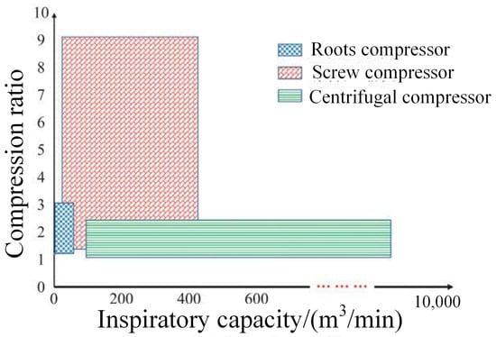
Figure 1.
Applicable range of different types of compressors.
There are less thorough design criteria to guide the design of key components in single-screw compressors. A preliminary analysis of the influence of water and oil injection, leakage, and working conditions was carried out through experimental or numerical simulation methods. Li et al. conducted research on single-screw refrigeration compressors, and the influence of discharge resistance, rotation speed, oil injection, and pressure ratio on the discharge process was analyzed in detail [22]. The performance of a system with a water injection compressor was tested and compared with a common compressor without water injection. The compression ratio and evaporation capacity increased with the increasing frequency, and the values with water injection were much higher [16]. The overall performance and the p-V diagrams on both sides of the single-screw compressor were measured based on a test rig. The asymmetrical working process will affect the mechanical properties of single-screw compressors [23]. In single-screw air compressors and single-screw refrigeration compressors, the operating temperature of the working medium is usually lower than 100 °C, so the thermal deformation of the rotor can be ignored compared with the design clearance. However, in the steam compression system, the operating temperature of the compressor is much higher than 100 °C, and the size of the device is also increased. In order to reduce the influence of machining accuracy, stress defects, and thermal expansion on operation performance, as well as ensure regular operation of the meshing process, the clearance between the relative moving parts must be reserved in the compressor [24]. When operating under high load conditions, water injection in the working chamber is usually used to achieve cooling, lubrication, and sealing effects [25]. Under the combined effect of high temperature difference and large size, thermal deformation of the critical components of the compressor is also more apparent, and the change in the fit clearance between the meshing pairs and the consequent differential expansion will also affect the reliability of the compressor [26]. Therefore, it is necessary to further analyze its thermal deformation and determine its application scope in industrial steam supply, which helps guide the selection of compressors and the design of steam compression technical processes.
The present study was carried out to study the thermal deformation of single-screw compressors using a numerical method. Firstly, the physical model was established and the numerical conditions and boundary conditions were determined according to the operating requirements of a 300 MW thermal power unit. Secondly, the deformation of different components was simulated and analyzed versus different simulated conditions. The reliability of single-screw compressors was limited when temperature exceeded 350 °C. Finally, the design of single-screw compressors under the control of differential expansion was analyzed and analysis of the design’s critical point was included.
2. Numerical Framework and Method
2.1. Steam Compression System and Parameters
The compression process of the reheat steam of a 300 MW thermal power unit was studied. For this 300 MW unit at 40% rated load, the original reheat steam temperature is 535 °C and the steam extraction pressure is only about 1.2 MPa. The reheated steam pressure can be increased to 1.9 MPa by adjusting the intermediate control valve. Therefore, the selection of 1.9 MPa pressure as the steam inlet parameter is typical for the reheat steam supply of 300 MW thermal power units; this pressure should be further compressed to 2.7 MPa. Meanwhile, the steam outlet temperature needs to be maintained above 480 °C. Table 1 lists the operating parameters of steam compression.

Table 1.
Working parameters of the screw compressor.
Considering the inlet steam temperature is high, two different compression systems are usually adopted in industrial practice, as shown in Figure 2. One is the direct high-temperature compression method (Figure 2a), which reduces steam temperature from 535 °C to about 350 °C and then compresses the steam to 2.7 MPa, at which time the corresponding steam outlet temperature is exactly 480 °C. The other approach is indirect high-temperature compression (Figure 2b). In this technical route, a steam-to-steam heat exchanger is added to exchange heat between the inlet steam (535 °C) and the compressor outlet steam, and the outlet steam is heated to 480 °C so that the steam temperature entering the compressor can be controlled to 210 °C. Meanwhile, the outlet steam temperature can be controlled to 230 °C through water spraying in the compression process to ensure the minimum temperature difference and temperature rise.
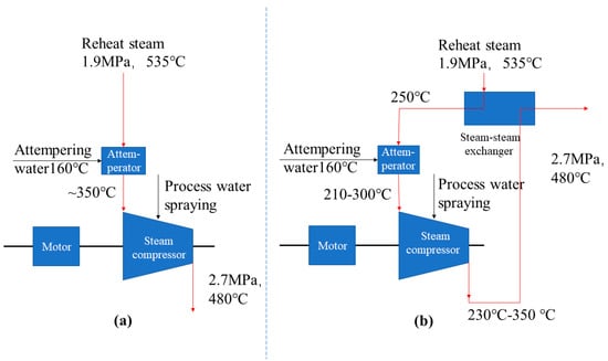
Figure 2.
Two different compression systems. (a) Direct high-temperature type (design outlet temperature 480 °C); (b) indirect high-temperature type (design outlet temperature 200–250 °C).
The simulation conditions used in this study were selected according to the requirements of these two different compression systems, with consideration of the optimal (210 °C/230 °C, inlet/outlet) and worst (535 °C/480 °C, inlet/outlet) temperature conditions. The chosen conditions are listed in Table 2.

Table 2.
The temperature under different working conditions.
2.2. Geometric Model
Figure 3 shows a three-dimensional model of a single-screw steam compressor. The single-screw compressor comprises a cylindrical screw and two star wheels symmetrically arranged on the same plane. The closed volume is surrounded by the screw groove, the inner wall of the cabinet (cylinder), and the star wheel teeth. The power is transmitted to the screw shaft, which drives the star wheel to rotate. The gas then enters the screw groove from the suction chamber and is compressed and discharged through the exhaust orifice and exhaust cavity. The star wheel acts as the piston of a reciprocating piston compressor, and when the star wheel teeth move relative to each other in the screw groove, the closed volume gradually decreases and the gas is compressed.
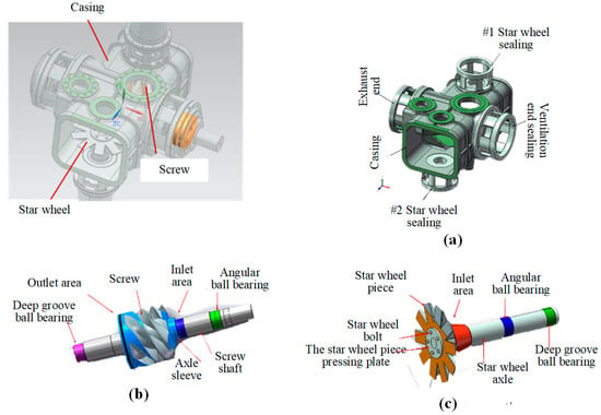
Figure 3.
Three-dimensional model of crucial components. (a) Cabinet assembly; (b) screw assembly; (c) star wheel assembly.
Because the time cost of the whole machine’s calculation is too high and the calculation is not easily converged, it is necessary to simulate each module separately. The cabinet assembly, screw assembly, and star wheel assembly were chosen for analysis in the simulation.
2.3. Thermal Deformation Analysis
Figure 4 shows a flow chart of the thermal deformation analysis of a single-screw compressor. The finite element method can be applied to conduct this simulation. Specifically, the ANSYS 2020R1 thermodynamic module is used to conduct steady-state thermal analysis and simulate the temperature distribution of modules. The thermal deformation of each node is then solved in the ANSYS statics module.
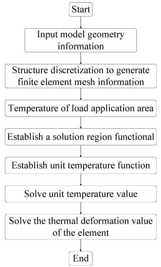
Figure 4.
Flow chart of thermal deformation analysis.
2.4. Boundary Condition
The boundary and constraint conditions were set with inlet temperature of 210 °C and an outlet temperature of 230 °C. Table 3 shows details of the materials. Table 4 lists some parameters of a single-screw compressor under this working condition. Table 5 gave the boundary conditions and some parameters in this simulation.

Table 3.
The material parameters.

Table 4.
Gas conditions and material parameters.

Table 5.
Boundary conditions and parameters.
As shown in Figure 5, each mechanical component is divided into different areas according to the boundary conditions, which are summarized below.

Figure 5.
Temperature boundary conditions. (a) Cabinet assembly; (b) screw assembly; (c) star wheel assembly.
- (1)
- Cabinet assembly. The gas inlet chamber, star wheel chamber, and exhaust gas chamber all adopt the convective heat transfer boundary condition. The outside of the cabinet is cooled by the forced air, and the ambient temperature is set as 35 °C with an air flow velocity of 1.5 m/s. The cooling water (160 °C) is sprayed into the compression chamber through the blowhole. The specific temperature boundary parameters are as follows: Region A, blowhole, constant temperature, t = 160 °C; Region B, gas inlet area (inlet hole, star wheel chamber, gas inlet chamber), h = 819.77 W/(m2·K), t = 210 °C; Region C and Region D, outlet area (outlet chamber and vent), h = 2503.3 W/(m2·K), t = 230 °C; Region E, outer surface of cabinet assembly, h = 4.78 W/(m2·K), t = 35 °C (as shown in Table 4).
- (2)
- Screw assembly. Region A involves the screw, part of the screw shaft, and the shaft sleeve at the inlet side of the cabinet (h = 819.77 W/(m2·K), t = 210 °C). Region B is a section perpendicular to the axis direction at the beginning of the exhaust port (h = 2503.3 W/(m2·K), t = 230 °C). Region C is the shaft wall surface where the two bearings are in contact, and the lubricating oil is used to cool the bearing (h = 493.54 W/(m2·K), t = 50 °C), as shown in Table 4.
- (3)
- Star wheel assembly. Region A includes the side of the screw bracket, part of the screw shaft surface in the star wheel cavity, the surface of the star wheel blade that is not meshed, the star wheel’s pressure plate, and the bolt surface (h = 819.77 W/(m2·K), t = 210 °C). The boundary conditions of Region B are similar to those of Region A in the screw assembly (h = 819.77 W/(m2·K), t = 210 °C), as shown in Table 4.
The load distribution of the cabinet was determined according to the inlet and outlet gas pressure. The pressure at the inlet area (Region B) was 1.9 MPa, and the exhaust pressure (Region C and Region D) was 2.7 MPa. The outside of the cabinet (Region E) was set to an atmospheric pressure of 0.1 MPa.
At present, three countermeasures to thermal deformation of the key mechanical components of single-screw compressors are generally applied [22]: (1) adjusting the design clearance and assembly position of the screw, star wheel, and cabinet directly, (2) applying reverse compensation correction to the rotor, and (3) controlling the differential expansion of the meshing pair. The cabinet and star wheel–screw meshing pair of the compressor have a very complex geometry, and it is relatively difficult to directly modify the mechanical structure or assembly position in actual engineering. In addition, since the amount of reverse compensation correction is much smaller than the geometric size of the actual compressor, the thermal deformation generated by the correction has little effect on the overall thermal deformation. Therefore, in this paper, the constraints are considered appropriately based on analysis of the differential expansion of the meshing pair. Meanwhile, in the calculation of thermal deformation, the boundary conditions should be simplified according to the actual situation, and there can be multiple types of boundary conditions that meet the simulation requirements. Table 6 lists the constraint settings for some positions.

Table 6.
Constraint Settings.
The constraint conditions and external load distribution of the screw and star wheel are shown in Figure 6. The screw is constrained at two bearings (A and B). Constraint A is the locating bearing, whose axial displacement is zero, and the radial direction is free to expand. Constraint B is a deep-groove ball bearing. The contact surface is set with a radial displacement of zero and free expansion in the axial direction. The star wheel is constrained at two bearings (C and D). Constraint D is a locating bearing with an axial displacement of zero and free expansion in the radial direction. Constraint C is a deep-groove ball bearing, whose contact surface is set with a radial displacement of zero and free expansion in the axial direction. The force on the screw and star wheel is simplified to the surface gas pressure. The constraint condition of pressure is annotated in Figure 6, and residual surface pressure was set as 1.9 MPa.
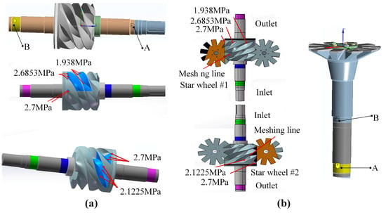
Figure 6.
Constraints of screw and star wheel assemblies. (a) Screw; (b) star wheel.
3. Results and Discussion
3.1. Analysis of Differential Expansion
The calculation results of differential expansion are shown in Table 7. When the designed clearance is 0.2 mm~0.3 mm, the differential expansion of star wheel and screw assemblies under conditions 1 to 3 can meet the design requirements (except for case 4).

Table 7.
Numerical results of differential expansion.
3.1.1. Inlet/Outlet Temperature of 210 °C/230 °C
As shown in Figure 7 and Figure 8, the axis deformation of the star wheel and screw is −1.03 mm and −1.07 mm, respectively. Correspondingly, differential expansion of the star wheel and screw is 0.04 mm and 0.08 mm with conversion. This degree of expansion already meets requirements, though it can be eliminated by adjusting the fit clearance or the axial assembly position.
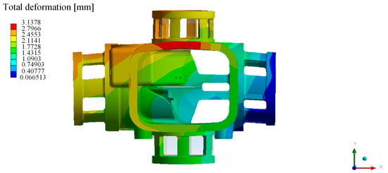
Figure 7.
Total deformation of the cabinet assembly.
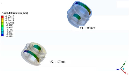
Figure 8.
Axial deformation of the star wheel shaft hole.
3.1.2. Inlet/Outlet Temperature of 300 °C/350 °C
In order to facilitate observation of the deformation of the cabinet assembly, the outline of the cabinet before and after the deformation is shown in Figure 9. It can be seen that the two ends of the cabinet expand less in an upward direction (Y direction), while the middle part expands significantly upwards (Y direction), resulting in the cabinet assembly showing a curved shape along the screw axis.
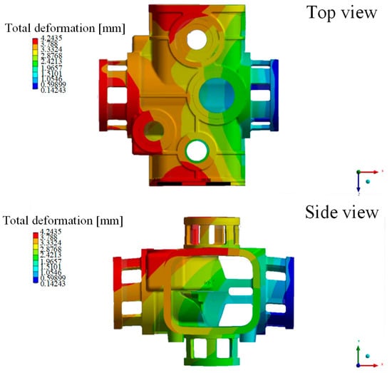
Figure 9.
Total deformation of the cabinet assembly (15× magnification). Top view and side view.
Axial deformation of the #1 and #2 star wheel shafts was −1.63 mm and −1.67mm, respectively. The path shown in Figure 10 is the intersection of the section (through the center of the circle and perpendicular to the axial direction of the screw) and the inner wall of the screw. It reveals that the range of axial offset is −1.44 m to −1.52 mm, and the average value is −1.48 mm. A negative sign represents an offset towards the exhaust side. Consequently, the offset of the star wheel shaft was 0.15 mm and 0.19 mm more than the screw origin for star wheel #1 and #2, respectively. The differential expansion of the star wheel screw can meet the design requirements since the design clearance is 0.2 mm~0.3 mm.
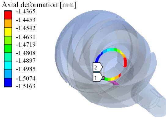
Figure 10.
Axial deformation of the screw origin.
3.1.3. Inlet/Outlet Temperature of 350 °C/350 °C
The overall deformation characteristics under this condition are consistent with those of Case 2 (inlet/outlet temperature of 300 °C/350 °C). The axial deformation of star wheel shafts #1 and #2 is −1.99 mm and −2.00 mm, respectively. The axial deformation of the screw origin varies from −1.6813 mm to −1.7609 mm, with an average value of −1.72 mm. Correspondingly, the offset of the star wheel shaft is 0.26 mm and 0.28 mm more than the screw origin for shaft #1 and #2, respectively. The differential expansion of the star wheel screw also satisfies the design requirements (0.2 mm~0.3 mm).
3.1.4. Inlet/Outlet Temperature of 535 °C/480 °C
The axial deformation of star wheel shafts #1 and #2 is −3.26 mm and −3.22 mm, respectively. The axial deformation of the screw origin is between −2.65 mm and −2.73 mm, with an average value of −2.69 mm. Hence, the offset of the star wheel shaft is 0.57 mm and 0.53 mm more than the screw origin. Because the temperature is too high in this case and the inlet temperature is higher than the exhaust temperature, differential expansion between the star wheel shaft and the screw significantly exceeds the design value.
3.2. Analysis of Equipment Selection
During the actual equipment design and manufacturing, the above ideal constraints should be satisfied as much as possible. Although the single-screw steam compressor faces the problem of thermal deformation, the clearance variation caused by thermal deformation can be solved by simply adjusting the design clearance or adopting reverse compensation correction. For differential expansion between the meshing pairs, different countermeasures can be applied according to the size of the equipment and operating temperature.
In fields demanding low steam flow and low steam temperature, such as sewage treatment, the size and temperature difference of the single-screw compressor are relatively small (the screw diameter is less than 420 mm, and the maximum temperature is about 152 °C). Hence, thermal deformation is usually not obvious, and differential expansion can be effectively solved. Industrial practice shows that the single-screw compressor has good mechanical efficiency and reliability in the sewage treatment process.
Nevertheless, the size and temperature difference of the single-screw compressor will increase significantly if the steam flow is large and the operating temperature is high. From the above simulation results, it can be seen that when the steam temperature does not exceed 350 °C, the support structure of the compressor can be adjusted to ensure that thermal deformation and differential expansion fall within an allowable range. However, when the temperature exceeds 350 °C, the reliability of the single-screw steam compressor decreases. As shown in Case 4, the thermal deformation of mechanical components significantly increases (screw diameter is above 720 mm, and the maximum temperature is 535 °C). In terms of this condition, either the design size of the compressor should be reduced or the operating temperature should be limited so as to satisfy the design requirements.
Under the temperature and flow conditions of Case 3 (350 °C, 130 m3/min), differential expansion of the meshing pair reached 0.26 mm–0.28 mm, which is very close to the design clearance (0.30 mm). Namely, steam flow and outlet temperature reached the design’s critical point. Taking these working conditions as the critical points, references for equipment design and selection can be obtained, as shown in Figure 11. When the flow rate and temperature are within the reference range, the single-screw compressor can be designed to adapt to the working conditions.
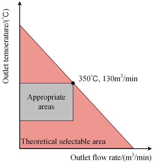
Figure 11.
Selection range of the single-screw compressor.
3.3. Application Expansion of Compressors
The single-screw compressor has many applications in terms of the saturated compression of high-pressure steam. If the outlet temperature is controlled at 315 °C and the compression process is close to the steam saturation state (spray water can be applied during the compression process to reduce the temperature), the outlet steam pressure of the compressor can reach 10 MPa and the maximum flow rate is close to 300 t/h. In some applications where the inlet’s volume flow is large, the inlet’s steam pressure is low, and a high pressure rise ratio is required, a combined compression system in the form of centrifugal steam compressors plus a screw compressor can be adopted. Specifically, under the condition of large steam volume flow, the preliminary compression process (small pressure rise ratio) is initially completed by the centrifugal compressor, which can depend on single-stage centrifugal compression or multi-stage centrifugal compression. When the volumetric flow rate is reduced to the range of working conditions applicable to the single-screw compressor, the single-screw compressor can be used for compression and a large pressure rise ratio applied. This technical measure broadens the application of steam compressors in industrial steam pressurization. Figure 12 shows the working range of this combined compression method, which can basically cover current industrial steam compression requirements. Meanwhile, the cost of the combined compression system is acceptable.
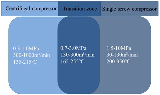
Figure 12.
Working conditions of combined compression with a single-screw compressor and centrifugal compressor.
In terms of situations where a specific degree of superheat is required, a steam compressor with an ordinary resistance heating module can be applied. In addition to this, steam superheating can also be realized through use of the centrifugal compression method with reflux adjustment, as shown in Figure 13. The latter measure adapts to the requirements of various voltage levels (0.4 kV–20 kV), which solves shortcomings related to the use of resistive superheaters.
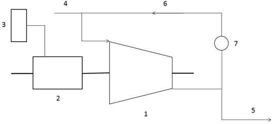
Figure 13.
System of a centrifugal steam compressor with reflux. 1—steam compressor, 2—motor, 3—frequency conversion device, 4—steam inlet, 5—steam outlet, 6—reflux regulation bypass, 7—reflux regulation valve.
4. Conclusions
In this work, two different steam compression processes, direct heating compression and indirect heating compression, are proposed to satisfy the requirement of industrial steam compression and supply. The compression process of a single-screw compressor under four different boundary conditions was analyzed using thermodynamic and static simulation methods. Results show that the differential expansion of the vertical meshing pair can be effectively controlled if the steam temperature is lower than 350 °C. When the temperature exceeds 350 °C, the reliability of the single-screw compressor cannot be ensured. According to thermal deformation analysis of several mechanical components under wide working conditions, an outlet steam temperature of 350 °C and an outlet volume flow rate of 130 m3/min are roughly the critical points for the temperature and flow of a single-screw steam compressor design. Hence, the design parameters of the compressor under different working conditions can be satisfied by reducing steam temperature or flow rate. In addition, several measures can be applied to expand the application of steam compressors in industrial steam pressurization, such as adopting the cascade compression method with a centrifugal compressor, maintaining a near-saturated steam state during the compression process through water spray cooling, and using a centrifugal compression method with reflux adjustment to increase the superheat degree of steam.
Author Contributions
Conceptualization, P.Z., X.K. and W.W.; software, P.Z.; validation, X.K., W.W. and J.L.; investigation, P.Z.; resources, P.Z.; data curation, P.Z.; writing—original draft preparation, P.Z.; writing—review and editing, X.K., W.W., X.T., J.L. and Q.T. All authors have read and agreed to the published version of the manuscript.
Funding
This work was supported by the Key Project of the National Fourteen-Five Year Research Program of China (2022YFB4100805).
Conflicts of Interest
The authors declare no conflict of interest.
References
- Takeshita, T.; Aki, H.; Kawajiri, K.; Ishida, M. Assessment of utilization of combined heat and power systems to provide grid flexibility alongside variable renewable energy systems. Energy 2021, 214, 118951. [Google Scholar] [CrossRef]
- Liu, J.X.; Xi, Z.; Li, X.H.; Yang, Q.P.; Xu, H.X.; Du, G.D. Numerical study on the overall performance and flow field characteristics of industrial steam compressor. Shanxi Prov. Inst. Mech. Eng. 2014. [Google Scholar] [CrossRef]
- Mabrouk, A.A.; Nafey, A.S.; Fath, H.E.S. Analysis of a new design of a multi-stage flash–mechanical vapor compression desalination process. Desalination 2007, 204, 482–500. [Google Scholar] [CrossRef]
- Huang, Z.K.; Zhang, P.; Du, X.; Zhang, F.F.; Liu, Y.H.; Sun, B.; Li, X.; Wang, J.D.; Liang, Y.P. Adjusting Method of Steam Compressor in Application System of Upgrading and Heat Supplying of Exhausted Steam of Thermal Power Generating Unit Steam Turbine. CN106930792B, 8 December 2017. [Google Scholar]
- Zhang, P.; Huang, Z.K.; Du, X.; Zhang, F.F.; Liu, Y.H.; Sun, B.; Li, X.; Wang, J.D.; Liang, Y.P. Reconstruction Method for Boosting Steam Supply Branch Network of Steam Compressor and Reducing Extraction Parameters. CN106968736B, 21 August 2018. [Google Scholar]
- Chen, T.; Li, Y.; Shen, Y.B.; Zhang, P.; Huang, Z.K.; Wang, E.Z.; Sun, R.; Wei, G.Y.; Liu, Y.H. A Heat Supply System Combined with Steam Compressor and High Back Pressure Heat Supply and Its Regulating Method. CN112228940B, 3 May 2022. [Google Scholar]
- Zhao, B. Performance Analysis on Water Vapor Recompression System. Master’s Thesis, Beijing University of Technology, Beijing, China, 2012. [Google Scholar]
- Mansour, A.; Muller, N. A review of flash evaporation phenomena and resulting shock waves. Exp. Therm. Fluid Sci. 2019, 107, 146–168. [Google Scholar] [CrossRef]
- Zhang, W.; Li, X.H.; Hui, M. Technology of high performance MVR vapor compressor and it’s application. Energy Sav. Nonferrous Metall. 2016, 32, 35–38+43. [Google Scholar]
- Zhang, H.F.; Yang, L.W.; Zhang, Z.T.; Lin, X.J.; Yang, J.L.; Zhang, C. Experimental study of operating characteristics of mechanical vapor Recompression heat pump evaporator system driven by roots Blower. Energy Conserv. Technol. 2015, 33, 113–117. [Google Scholar]
- Shen, J.B.; Xing, Z.W.; Zhang, K.; He, Z.L.; Wang, X.L. Development of a water-injected twin-screw compressor for mechanical vapor compression desalination systems. Appl. Therm. Eng. 2016, 95, 125–135. [Google Scholar] [CrossRef]
- Matsuda, R.J.; Qi, P.Y. Screw Steam Compression Heat Pump. Mech. Electr. Equip. 1986, 4, 18–26. Available online: http://www.cnki.com.cn/Article/CJFDTotal-JDSP198604003.htm (accessed on 22 March 2023).
- Patel, H.H.; Lakhera, V.J. A critical review of the experimental studies related to twin screw compressors. Proc. Inst. Mech. Eng. Part E J. Process Mech. Eng. 2020, 234, 157–170. [Google Scholar] [CrossRef]
- Zimmern, B. Worm Rotary Compressors with Liquid Joints. U.S. Patent 3180565, 6 May 1965. [Google Scholar]
- Cha, Q.; Liu, X.Q.; Fang, Y.R.; Cha, S.L. Present situation and development trend of single screw compressor. Fluid Mach. 1997, 2, 40–42. [Google Scholar]
- Yang, J.L.; Zhang, C.; Zhang, Z.T.; Yang, L.W.; Lin, W.Y. Study on mechanical vapor recompression system with wet compression single screw compressor. Appl. Therm. Eng. 2016, 103, 205–211. [Google Scholar] [CrossRef]
- Hu, B.; Wu, D.; Wang, R.Z. Water vapor compression and its various applications. Renew. Sust. Energ. Rev. 2018, 98, 92–107. [Google Scholar] [CrossRef]
- Yang, J.L.; Yang, L.W.; Zhang, Z.T. Review on Energy-saving Technology with MVR. Chin. J. Turbomach. 2016, 58, 84–88. [Google Scholar]
- Wang, L.W.; Zhuang, J.F.; Yang, L.W.; Lin, W.Y.; Zhang, Z.T.; Yang, L.P.; Zhang, J.H. Experimental study on performance of MVR system driven by single screw water vapor compressor. J. Univ. Chin. Acad. Sci. 2015, 32, 38–48. [Google Scholar]
- Degueurce, B.; Banquet, F.; Densant, J.; Favrat, D. Use of a twin screw compressor for steam compression. Hydraul. Pneum. Mech. Power 1984, 30, 335–337. [Google Scholar]
- Chamoun, M.; Rulliere, R.; Haberschill, P.; Peureux, J.L. Modelica-based modeling and simulation of a twin screw compressor for heat pump applications. Appl. Therm. Eng. 2013, 58, 479–489. [Google Scholar] [CrossRef]
- Li, J.; Feng, Q.K.; Liu, F.L.; Wu, W.F. Experimental studies of the tooth wear resistance with different pro-files in single screw compressor. Tribol. Int. 2013, 57, 210–215. [Google Scholar] [CrossRef]
- Wu, W.F.; Zhang, Z.; Peng, C.Y.; Li, X.W.; Yang, Y.F.; Lei, W.W. Refreshed internal working characteristics of the single screw compressor based on experimental investigation. Int. J. Refrig. 2022, 143, 118–125. [Google Scholar] [CrossRef]
- Zhang, Z.; Wu, W.F. Numerical investigation of thermal deformation of meshing pairs in single screw compressor. Appl. Therm. Eng. 2021, 188, 116614. [Google Scholar] [CrossRef]
- Novelo, D.A.B.; Igie, U. Aero engine compressor cooling by water injection—Part 1: Evaporative compressor model. Energy 2018, 160, 1224–1235. [Google Scholar] [CrossRef]
- Wang, Z.L.; Wang, Z.B.; Wang, J.; Jiang, W.C.; Feng, Q.K. Theoretical and experimental study on thermodynamic performance of single screw refrigeration compressor with Multicolumn Envelope Meshing Pair. Appl. Therm. Eng. 2016, 103, 139–149. [Google Scholar] [CrossRef]
Disclaimer/Publisher’s Note: The statements, opinions and data contained in all publications are solely those of the individual author(s) and contributor(s) and not of MDPI and/or the editor(s). MDPI and/or the editor(s) disclaim responsibility for any injury to people or property resulting from any ideas, methods, instructions or products referred to in the content. |
© 2023 by the authors. Licensee MDPI, Basel, Switzerland. This article is an open access article distributed under the terms and conditions of the Creative Commons Attribution (CC BY) license (https://creativecommons.org/licenses/by/4.0/).