Article

Experimental Characterization of an Additively Manufactured Inconel 718 Heat Exchanger for High-Temperature Applications

Advanced Heat Exchangers and Process Intensification Laboratory, Department of Mechanical Engineering, University of Maryland, College Park, MD 20742, USA
*
Author to whom correspondence should be addressed.
Energies 2023, 16(10), 4156; https://doi.org/10.3390/en16104156
Submission received: 1 March 2023 / Revised: 24 April 2023 / Accepted: 26 April 2023 / Published: 17 May 2023
(This article belongs to the Special Issue Advances in Thermal and Fluid Science)

Abstract

:
This work presents the experimental results of a novel, air-to-air, additively manufactured manifold-microchannel heat exchanger with straight fins on both sides. The heat exchanger was made of Inconel 718 using a direct metal laser sintering technique. The overall core size of the heat exchanger was 94 mm × 87.6 mm × 94.4 mm, with a fin thickness of 0.220 mm on both the hot and cold sides. The heat exchanger was tested with pressurized nitrogen gas at 300 °C and 340 kPa for the hot side, while air at an ambient condition was used for the cold side. An overall heat transfer of 276 W/m2K was obtained for Reynolds number values of 132 and 79 for the cold and hot sides, respectively. A gravimetric heat transfer density (Q/mT) of 4.7–6.7 W/kgK and a volumetric heat transfer density (Q/VT) of 6.9–9.8 kW/m3K were recorded for this heat exchanger with a coefficient of performance value that varied from 42 to 52 over the operating conditions studied here. The experimental pressure drop results were within 10% of the numerical values, while the corresponding heat transfer results were within 17% of the numerical results, mainly due to imperfections in the fabrication process. Despite this penalty, the performance of the tested heat exchanger was superior to the conventional plate-fin heat exchangers: more than 60% of improvements in both gravimetric and volumetric heat transfer densities were recorded for the entire range of experimental data.

1. Introduction

The need for heat exchangers that are able to withstand high-temperature and high-pressure conditions and be light and compact (good mass and volume-based power densities) is driving the research community to explore innovative designs and new materials and fabrication techniques to respond to the need in this area. Utilizing these heat exchangers in high-temperature and high-pressure cycles, such as supercritical carbon dioxide (sCO2) power generation cycles, can yield higher fuel-to-shaft power efficiencies, thus leading to substantial energy savings and CO2 footprint reduction. Many sectors can benefit from such cycles for power generation and waste heat recovery applications. The need for high-performance and high-power density heat exchangers that meet life cycle durability and reliability requirements is significant in the aerospace industry for emerging applications, such as next-generation, more electric, and hybrid-electric aircraft. High-performance heat exchangers are also essential for the Environmental Control Systems (ECSs) of aircraft to provide a thermally suitable environment for people onboard, as well as for avionics and other systems. The ECS provides conditioned air to pressurize the passenger cabin and controls temperature and fresh air ventilation by moderating the outflow valves [1]. For air-conditioning, the source of air used by the ECS is typically bleed air from the gas turbine compressor, which is available at high temperatures and high pressures. The hot bleed air is then cooled to an acceptable temperature level before entering the passenger cabin. This is achieved using an air-conditioning package comprising subsystems, including heat exchangers (HXs), which are cooled by ambient ram air. The requirements for those HXs are (1) compactness and lightweight qualities, (2) high temperature (HT) and high pressure (HP) resistance, (3) high effectiveness and minimum pressure drop, and (4) good reliability and life cycle durability [2].
The selection of HXs for the ECS is, therefore, a complex problem that involves the choice of material, design, and fabrication method. Among the possible materials, ceramics can withstand the highest temperature [3,4]. The most common ceramic used for high-temperature heat exchangers (HTHXs) is sintered silicon carbide (SiC) [5,6], which has been adopted for applications with temperatures above 1000 °C [6]. The main drawback of ceramics, however, is their brittle nature concerning tensile stresses [7], which limits the choice of this material for HP applications. The only reference found in the literature is a few ceramic HXs developed using SiC, with a temperature limit of 1090 °C, but with limited other technical details disclosed [8]. State-of-the-art HXs for bleed air cooling in an aircraft are made of metals. This choice is based on the temperature at which the component needs to operate under continuous service and reliability considerations. A combination of superalloys and stainless steel has been found to be among the preferred choices for state-of-the-art HTHXs for applications of up to 760 °C, while superalloys exclusively have been adopted for applications with temperatures of up to 815 °C [8,9,10,11].
Some state-of-the-art HXs for bleed air cooling in aircraft applications employ a plate-and-fin design [12]. Plate-and-fin heat exchangers (PFHXs) consist of alternating layers of a hot fluid-finned surface, a separating palate, and a cold fluid-finned surface. The presence of the fins enhances the heat transfer area-to-volume ratio on the order of 800–1500 [13], thus assisting with achieving a better power density for the heat exchanger. However, this added performance gain often carries an inevitable increase in pressure drop per unit flow length [14]. Pressure drop and heat duty requirements raise the standards, particularly for aerospace HXs, to deliver more compact heat exchangers without affecting the heat duty; these requirements underline the need for enhanced designs to surpass the current ones [15]. Moreover, for high-temperature applications, there are challenges associated with fabricating fins out of superalloys. Some design solutions include fins that are usually manufactured out of stainless steel and then brazed onto the separating plate made from a higher-temperature material, such as a superalloy [13].
Significant efforts have been made to develop novel and compact HTHPHXs from superalloy materials. Some works adopting Printed Circuit Heat Exchangers (PCHX) have shown promise in handling high temperature and pressure conditions [16,17,18]. However, they tend to have thick fins and separating walls which significantly increase their mass; thus, they have a lower power density and are often not a suitable choice for the ECS of an aircraft’s application. In fact, no PCHX designs for aerospace applications can be found in the literature. Other works have focused on microchannels to further increase the heat exchanger compactness over that of PFHXs [19], such as the work by Kanlayasiri et al. [20], in which they fabricated a microchannel heat exchanger (MHX) from nickel aluminide (NiAl) using novel methods for material synthesis: NiAl machining, and NiAl bonding. The HX was developed to help miniaturize microtechnology-based energy and chemical systems and was successfully tested, though only up to one-atmosphere pressure. Despite the promising results, HX was intended for small-scale applications, while the large size of HXs for ECSs may make their proposed fabrication process too slow and time-consuming. An example of MHX in aerospace applications can be found in the work of Strumpf and Mirza [15]. They developed a full-scale HX which could offer a 30% reduction in core volume compared to the existing unit when used as the reference. Although this HX was designed for air-to-fuel and not an ECS, it shows the advantage of using small passage sizes (less than 0.028 in (700 µm) to enhance performance. However, this HX was made of aluminum, and the authors have not developed a manufacturing process to obtain the same design out of stainless steel or superalloy. It is, therefore, clear that one of the biggest challenges in realizing high-performance HTHPHXs is the fabrication process. High-performance HXs often require a complex design that is challenging to fabricate using conventional methods. This underlines the need to contemplate advanced manufacturing technologies.
Additive manufacturing (AM) is an advanced fabrication technique where parts are produced in layers using a pre-programmed digital model. Due to its additive nature, most of the challenges met in superalloy fabrication are not faced in AM. There have been many investigations on using AM to fabricate advanced metallic HXs for various applications, such as aerospace, electronics cooling, and gas turbine cooling, as summarized in Table 1. It can be observed that Selective Laser Melting (SLM), Direct Metal Laser Sintering (DMLS), and Electron Beam Melting (EBM) are the most common metal-based AM techniques used. The parts are produced by melting/sintering powder metal via high-power sources (laser/electron beam) to give the desired shape. Most of these works highlight the performance advantages of additively manufactured HXs, such as a printing resolution capability, the material used, and the different shapes that AM can fabricate. A more detailed study in the literature on the benefits of AM in thermal management devices (not only HXs) can be found in [21,22,23].
Out of the additively manufactured designs reported in Table 1, the manifold-microchannel heat exchanger (M2HX) showed the most promising results, as it could increase the heat transfer coefficient without a significant increase in pressure drop. Therefore, this investigation focused on the fabrication and testing of an M2HX. Compared to previous work on M2HXs, this HX was printed with an innovative orientation that allowed for higher fin density and enhanced fluid-flow management, decreasing flow maldistribution. A significant improvement in performance gain over conventional PFHX was reported compared to the previous works by Zhang et al. [24]. Moreover, the size of the fabricated unit (94 mm × 87.6 mm × 94.4 mm) was six times bigger than the previous works by Zhang et al. [24], which showed the scaling-up capability of the concept. The tested M2HX could be compared to state-of-the-art heat exchangers to demonstrate its superior performance.

2. Heat Exchanger Geometry and Fabrication

The HX presented in this work was based on a manifold-microchannel design, where a system of flow distributors (the manifold) was placed on top of the microchannels in an assembly of alternating structures of microchannels and manifolds. The crossflow gas-to-gas M2HXs assembly is shown in Figure 1: stacking more layers increased the heat transfer area and capacity of the HX. Figure 1 also indicates that the flow enters the manifold channels, which then distributes them into a microchannel structure through the opening W i n . The fluid enters the microchannel, causing splitting in two opposite directions. The two opposite flows were eventually united and exited through the adjacent manifold channel. Due to the small mass flow rate and short flow length in the microchannel, the flow in the laminar developing region was characterized by high heat transfer coefficients. In addition, a short flow length can also reduce the pressure drop, which, in turn, reduces the pumping power requirement. For those reasons, M2HXs can be among the most suitable for aerospace applications.
The HX geometry is based on a 16.6 L optimized HX that was designed to replace a conventional ECS system. The optimization procedure used was the same as the one described in the works conducted by Arie et al. [37] and Zhang et al. [38]. However, due to the 3D printer’s build volume limitation, a 1 L scaled-down unit was selected for fabrication. The geometrical parameters for both the hot and the cold sides are shown in Table 2 (see Figure 1 for the definition of the parameters). N was the overall number of stacks for HX. As shown in Figure 1, M2HX features a repeating elementary geometry in the z-axis. Stack refers to the portion of HX that includes a base plate with the crossflow microchannels on the two sides and half of the manifold channels in the L n o f l o w (see Figure 1). n is used to indicate the number of microchannels for each side of a stack for the M2HX.
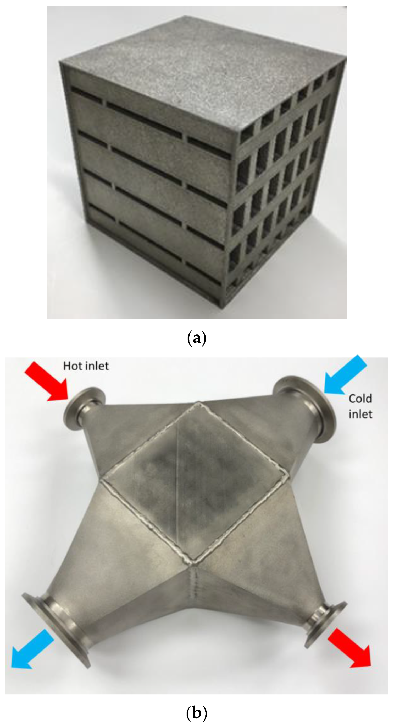
The HX was printed out of Inconel 718 using a ProX-300 printer. It is important to emphasize that this is the first M2HX printed with straight fins and straight manifolds on both sides. Zhang et al. fabricated the M2HX with inclined fins, which reduced its performance, as reported in Ref. [39]. This was made possible by orienting the part with a 45-degree inclination with respect to the build plate. This orientation allowed for a tolerable overhang of 45° for the entire HX, avoiding the need to alternate the fin design to account for printability constraints. From the performance point of view, an M2HX with straight fins accommodated a 30% higher fin density when compared to an inclined fin design (printed with the same printing resolution) and reduced the pressure drops. A detailed description of the printing procedure can be found in Ref. [39]. Once the printing was completed, the part was removed from the base plate via an EDM wire-cut process, and excess non-sintered powder was removed using an ultrasonic cleaner with deionized water. The fabrication result after the cleaning process is shown in Figure 2a.
To assess the fabrication quality, the actual mass of the fabricated HX (1.13 kg) was compared to the theoretical one, which was obtained by multiplying the volume obtained with the CAD and the density of Inconel 718. The difference between the two was found to be 3%, which confirmed the absence of major clogging or a significant deviation of the internal features. A computed tomography scan (CT scan) was performed on a portion of the HX (38 mm × 38 mm × 38 mm) to analyze the quality of the fins. The resolution of the scan was 0.035 mm, and the fins were measured as 0.220 mm. These measurements confirmed the predicted size, further validating the success of the print (see Ref. [39] for more info). HX was also tested under 340 kPa of pressurized air, and air tightness was demonstrated. The core was then welded to the four headers shown in Figure 2b. These headers were also 3D printed out of Inconel 718, showing once more the advantage of this fabrication technique in terms of design flexibility.

3. Experimental Test Setup

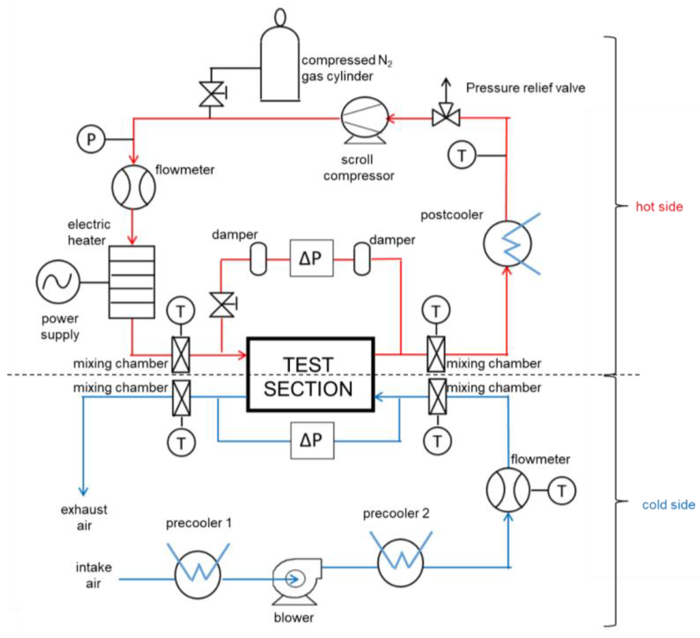
The fabricated M2HX was experimentally tested using pressurized N2 on the hot side and air on the cold side. The schematic diagram of the test setup is shown in Figure 3. The hot side consisted of a closed loop, where a compressed N2 gas cylinder was used to pressurize the system to the desired value. The total system pressure was measured with a pressure gauge reader. A scroll compress, controlled by a variable speed controller, provided the desired flow. A 13-kW electric heater was used to increase the temperature in the system. A post-cooler (an air-to-water HX connected to a 20-kW chiller) was installed to cool the flow from the test section outlet to the compressor’s inlet. The cold side was an open loop with atmospheric system pressure. Air was used as a working fluid, and a blower, controlled by a variable speed controller, was used to provide the desired flow. Two precoolers were installed, before and after the blower, to make that sure the temperature at the inlet of the test section was sufficiently low. Pressure transducers and high-temperature thermocouples were used to measure the pressure drops and temperatures across the test section. On both sides, mixing chambers ensured uniform temperature measurements at both inlets and outlets of the test section. Coriolis flow meters were used to measure the mass flow rates on both sides. All the measuring devices were connected to a data acquisition system to collect real-time values. A series of flange-clamp connections with high-temperature gaskets as interfacial elements were used to connect the different parts of the setup. High-temperature insulation was applied to cover the HX, the headers, and the mixing chambers to minimize heat losses. Infrared thermography was used to determine any heat loss sources. If heat loss sources were found, an additional high-temperature insulation was added.

4. Experimental Procedure and Data Reduction

The HX was tested by varying the hot-side mass flow rate ( m ˙ h o t ) from 7 to 13 g/s while keeping the cold-side mass flow rate ( m ˙ c o l d ) constant. This procedure was repeated for three values of cold-side mass flow rates: 15, 20, and 25 g/s. For all the tested points, the inlet hot and cold temperatures were set to constant at 300 °C and 25 °C, respectively, and the hot side was pressurized at 340 kPa. A summary of the experimental test conditions is shown in Table 3. For all flow rate variations, including the inlet and outlet temperature ( T i n and T o u t respectively), pressure drop ( p ), and mass flow rates were measured and recorded for both sides, while the total system pressure ( p h o t ) was measured for the hot side only.
First, the heat duty of HX was evaluated on each side individually, as shown in Equations (1) and (2), where c p is the specific heat of the fluid. Across all the tested points, the average energy balance between the hot and cold sides was determined to be 5% with a standard deviation of 3%. The departure from the ideal case of perfect energy balance can be explained by factors including a small heat leakage in the ambient, a non-perfectly mixed temperature condition at thermocouple locations, and the uncertainty of the measurements. The average value of Q h o t and Q c o l d was used to evaluate the performance of HX, as shown in Equation (3).
Q h o t = m ˙ h o t c p , h o t ( T i n , h o t T o u t , h o t )
Q c o l d = m ˙ c o l d c p , c o l d ( T o u t , c o l d T i n , c o l d )
Q = Q h o t + Q c o l d 2
From the collected measurements, it was also possible to define HX’s effectiveness ( ε ) using:
ɛ   = Q C m i n ( T i n , h o t T i n , c o l d )
where C m i n = min ( m ˙ c o l d c p , c o l d ; m ˙ h o t c p , h o t ) . The heat exchanger’s effectiveness is a measure of how effectively a heat exchanger transfers heat from one fluid to another fluid. Once the effectiveness is determined, the NTU can be calculated using the correlation for cross-flow HW with both fluids unmixed [40]. From the NTU definition, the overall heat transfer coefficient ( U ) can be obtained, which includes the convection on both sides and the conduction through the base (separating plate):
U = C m i n N T U A b a s e
where A b a s e is the total area of the base, which can be obtained by multiplying L h o t , L c o l d , and the number of stacks N (8 for this case). Besides the thermal performance, it is also important to evaluate the pressure drop of M2HX. It is, therefore, possible to express the mean friction factor ( f ) as:
f = p L f l o w 2 ρ D H , c h n v c h n 2
where ρ is the density of the fluid and v c h n is the velocity of the fluid in the microchannel. D H , c h n and L f l o w can be defined as (with reference to Figure 1):
D H , c h n = 2 H c h n W c h n H c h n + W c h n
L f l o w = L f l o w   p a t h   i n m a n i f o l d c h a n n e l + H m n d + 2 H m n d , b a s e + H c h n a v e r a g e   f l o w   p a t h   t o e n t e r   a n d   l e a v e m i c r o c h a n n e l + W m n d c h n W i n 2 a v e r a g e   f l o w p a t h   i n   m i c r o c h a n n e l
where L f l o w is the average flow path of the fluid from the entrance to the exit of the HX. It can be split into three terms corresponding to the three directions in which the fluid flows in an M2HX. Using the cold side of Figure 1 as the reference, the flow path in the ± x -axis corresponds to the flow length in the manifold channel, while the flow path in the ± z -axis represents the average distance traveled by the fluid to reach the microchannel from the manifold and to conversely return from the microchannel 2 × ( H m n d 2 + H m n d , b a s e + H c h n 2 ). The third term of Equation (8) is the flow path in the ± y -axis, which pertains to the average flow length in the microchannel.

5. Uncertainty Analysis

Uncertainty propagation analysis was performed to calculate the uncertainty of M2HX performance parameters ( Q , ε , U ). A list of measurement equipment is shown in Table 4 with its corresponding accuracies. The uncertainty of the calculated quantity Y , which is a function of X 1 , X 2 , , X N , with the uncertainty of U n X 1 , U n X 2 , , U n X N , can be calculated using the method explained in NIST Technical Note 1297 [41], defined as:
U n Y = i Y X i 2 U n X i 2
This method was implemented in the EES software and used to calculate the uncertainties of the derived performance parameters. The maximum uncertainties in Q , ε and U were evaluated as ±3.3%, 2.8% and 8.0%, respectively, and the error bars included in the results are presented in the next section.

6. Results and Discussion

6.1. Heat Transfer Performance

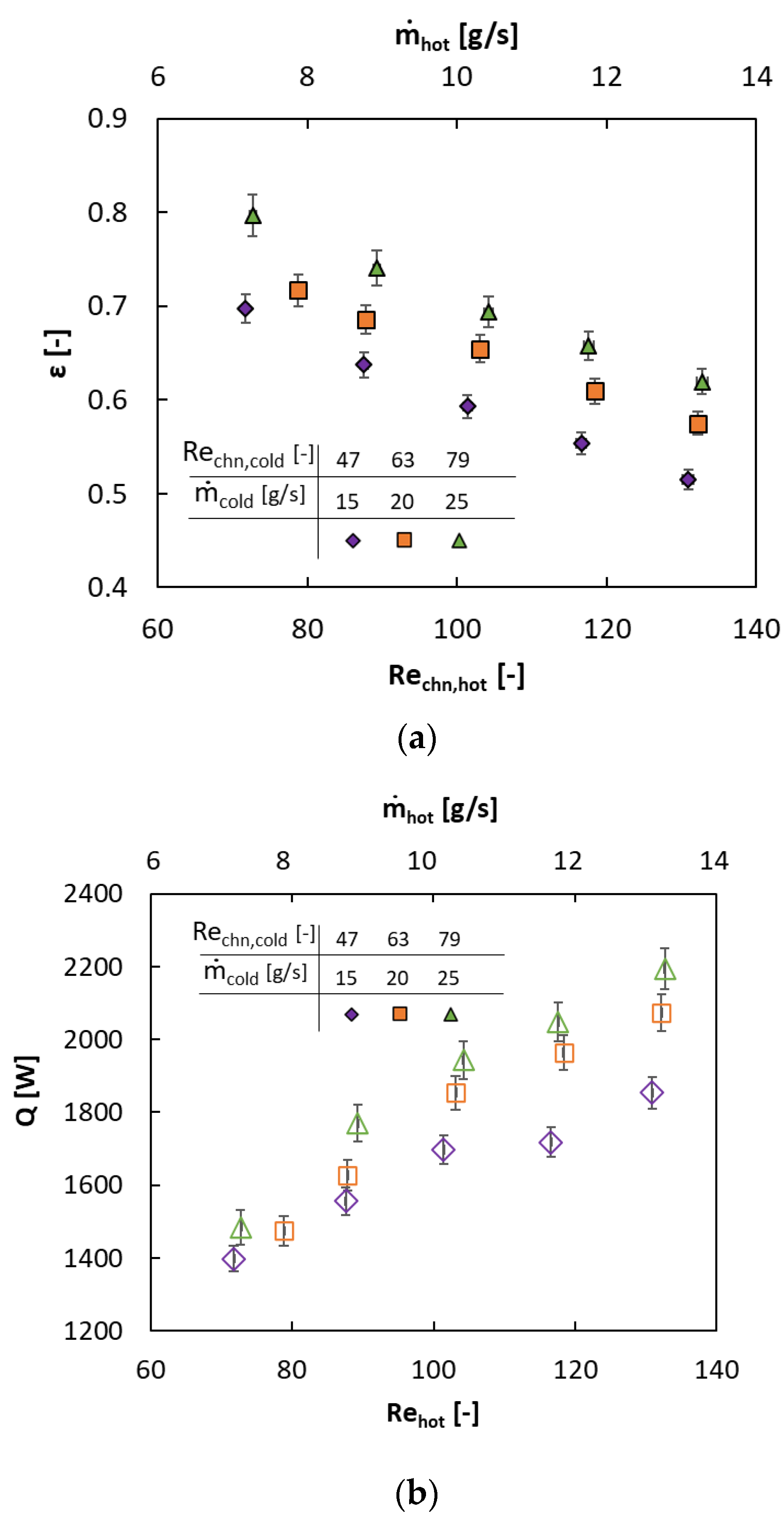
The heat transfer performance testing results are shown in Figure 4 for different values of cold-side mass flow rates while varying the hot-side mass flow rate. The results are plotted as a function of the Reynolds number ( R e ) of the flow in the microchannel, which can be defined as:
R e c h n = ρ   v c h n   D c h n μ
where μ is the viscosity of the fluid. Figure 4a,b shows the effectiveness of the HX and heat duty ( Q ) as a function of the hot-side Reynolds number ( R e c h n , h o t ) and the overall hot-side mass flow rate at the HX’s inlet ( m ˙ h o t ) (top x-axis). The graphs show the results for the three values of m ˙ c o l d tested: 15, 20, and 25 g/s and their corresponding R e c h n , c o l d .
Figure 4a shows that a maximum effectiveness of 80% was achieved for m ˙ c o l d = 25 g/s and m ˙ h o t = 7 g/s, which are respectively the highest value of m ˙ c o l d and the lowest value of m ˙ h o t in the range of the tested flow rates. This point corresponds, therefore, to the experimental condition with the lowest C r , which can be defined as the ratio of the C m i n and C m a x = m a x ( m ˙ c o l d c p , c o l d ; m ˙ h o t c p , h o t ) . Considering that C m i n always corresponds to the hot side for all the tested points, the definition of effectiveness given in Equation (4) can be rewritten as:
ε = T i n , h o t T o u t , h o t T i n , h o t T i n , c o l d
By increasing the hot-side mass flow rate, T o u t , h o t increases and a decrease in effectiveness was observed, as justified by Equation (11). The same result was obtained when the cold-side mass flow rate decreased, as shown in Figure 4a. When evaluating HX, however, it is essential to determine how the heat duty that can be transferred. Figure 4b shows how increasing the cold and hot side mass flow rates has a positive impact on Q , with a maximum value of 2200 W at R e c h n , c o l d = 79 and R e c h n , h o t = 132. Moreover, it is interesting to notice how increasing the hot side had a higher effect on heat duty than on the cold side. Increasing m ˙ h o t by 28.5% from 7 g/s to 9 g/s, increased Q by 11.3% while increasing m ˙ c o l d by 66.7% from 15 g/s to 25 g/s, increased Q by 6.3%. This is because the hot-side mass flow rate is significantly lower than the cold, resulting in a higher thermal resistance on the hot side that acts as the limiting factor.
The overall heat transfer coefficient as a function of R e c h n , h o t for the different cold-side flow rates is presented in Figure 4c. It can be observed that increasing the mass flow rate on either of the two sides increased the overall heat transfer coefficient. Overall, a heat transfer coefficient as high as 276 W/m2K was recorded for R e c h n , c o l d = 79 and R e c h n , h o t = 132. This was significantly higher than the typical overall heat transfer coefficient for shell and tube heat exchangers for gas-to-gas applications [42]. This improvement was due to a high fin density (thanks to the small size of the fins) and a short flow path in the microchannel (thanks to the manifold on top), allowing the fluid to exploit the high heat transfers of the entry region. The base thickness was also minimized to reduce thermal resistance while guaranteeing gas tightness under operating conditions.

6.2. Pressure Drop Performance

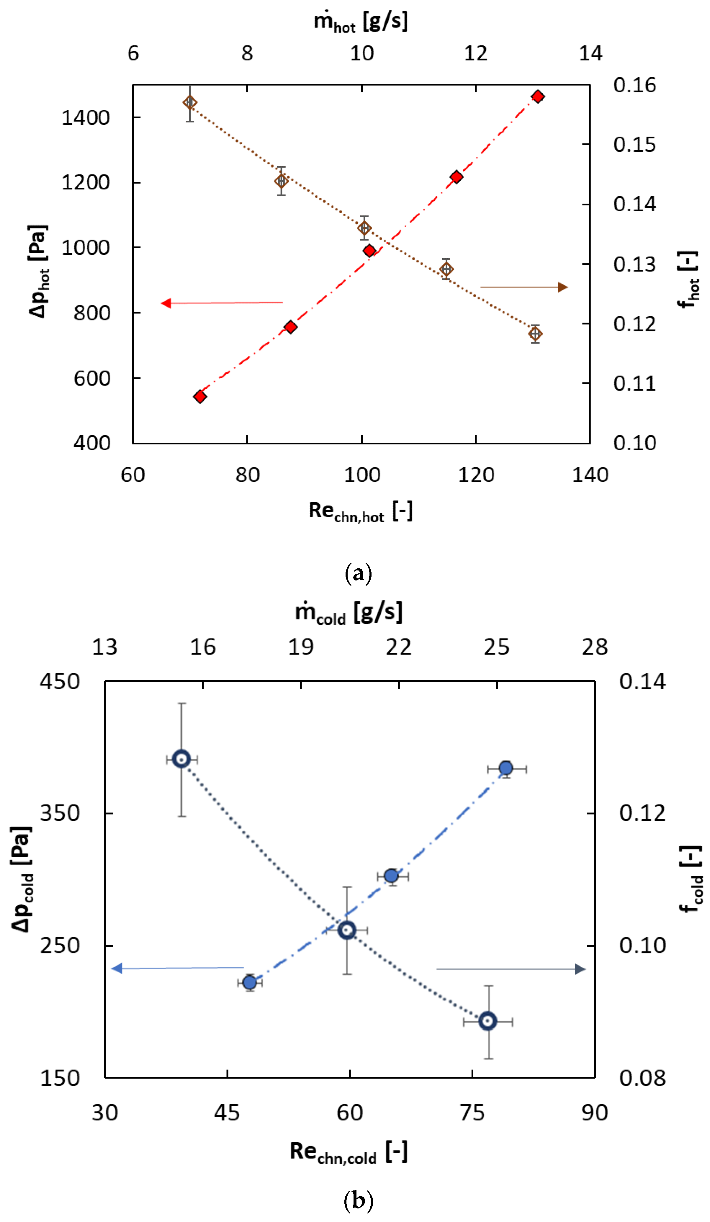
The pressure drop ( p ) for both sides is shown in Figure 5 (left y-axis) as a function of the R e c h n (bottom x-axis) and m ˙ (top x-axis). Both Figure 5a,b show the expected trend: a quadratic pressure drop increase with an increase in the flow rate, as shown by the data trending line. The difference in p between the hot and cold sides was due to the problem statement of HX’s design. However, using a pressure transducer with the same uncertainty for both sides resulted in a more considerable uncertainty on the cold side. Also, for the mass flow rates, the flowmeter used for the cold side had a bigger uncertainty, which is reflected in the reported graphs. Figure 5 also shows the trend in the friction factor f , as defined in Equation (6) (right y-axis). The friction factor f decreased with the increase in flow rates, which corresponded to an opposite trend compared to p . The difference in f values on the two sides was due to the different geometries, as shown in Table 2.

6.3. Comparison with Numerical Modeling

The experimental results can be compared to the predictions of the numerical models for M2HX. Arie et al. [43] developed a hybrid method that was capable of independently evaluating the pressure drop and heat transfer performance of each side of the M2HX. This model was, therefore, used to evaluate the pressure drop and heat transfer coefficient on each side. The heat spreading model developed by Mandel et al. [44] specifically for a double-sided, crossflow M2HX was used to evaluate the combined effect of the two sides and account for any smearing effect due to axial conduction. The main assumptions of those models were a uniform flow distribution in all microchannels, negligible heat transfer in the manifold compared to the heat transfer in the microchannels, constant fluid properties, isotropic solid properties, and uniform temperature at the base interfacial surface dividing the hot and cold sides. More information about the modeling procedure can be found in the works of Arie et al. and Mandel et al. [43,44]. A grid independence study was conducted to determine the minimum number of computational elements that were required to limit the computational time and provide an error of less than 1% before commencing the simulation. Based on this study, it was determined that approximately 260,000 computational elements would be adequate for this purpose.
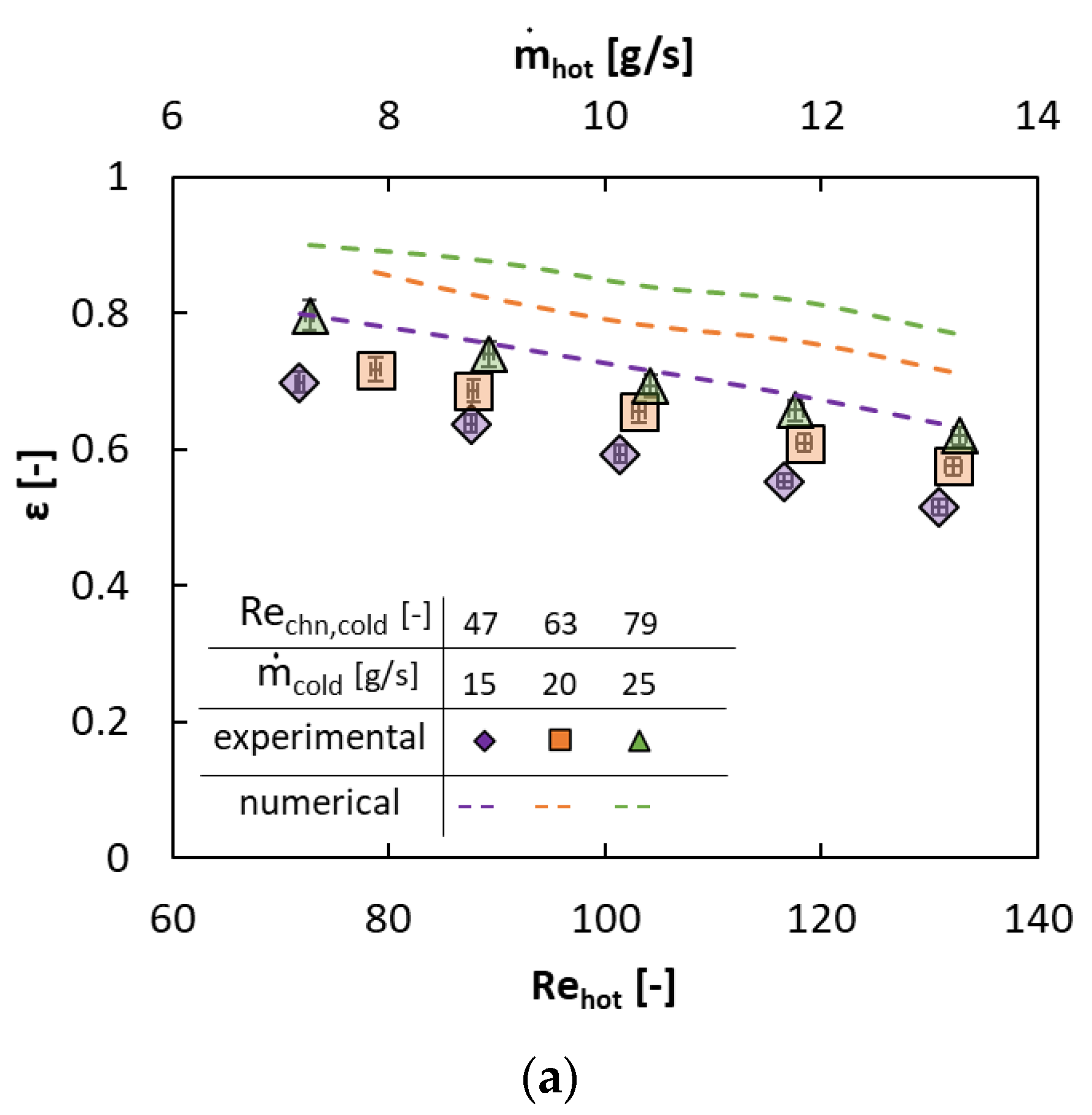
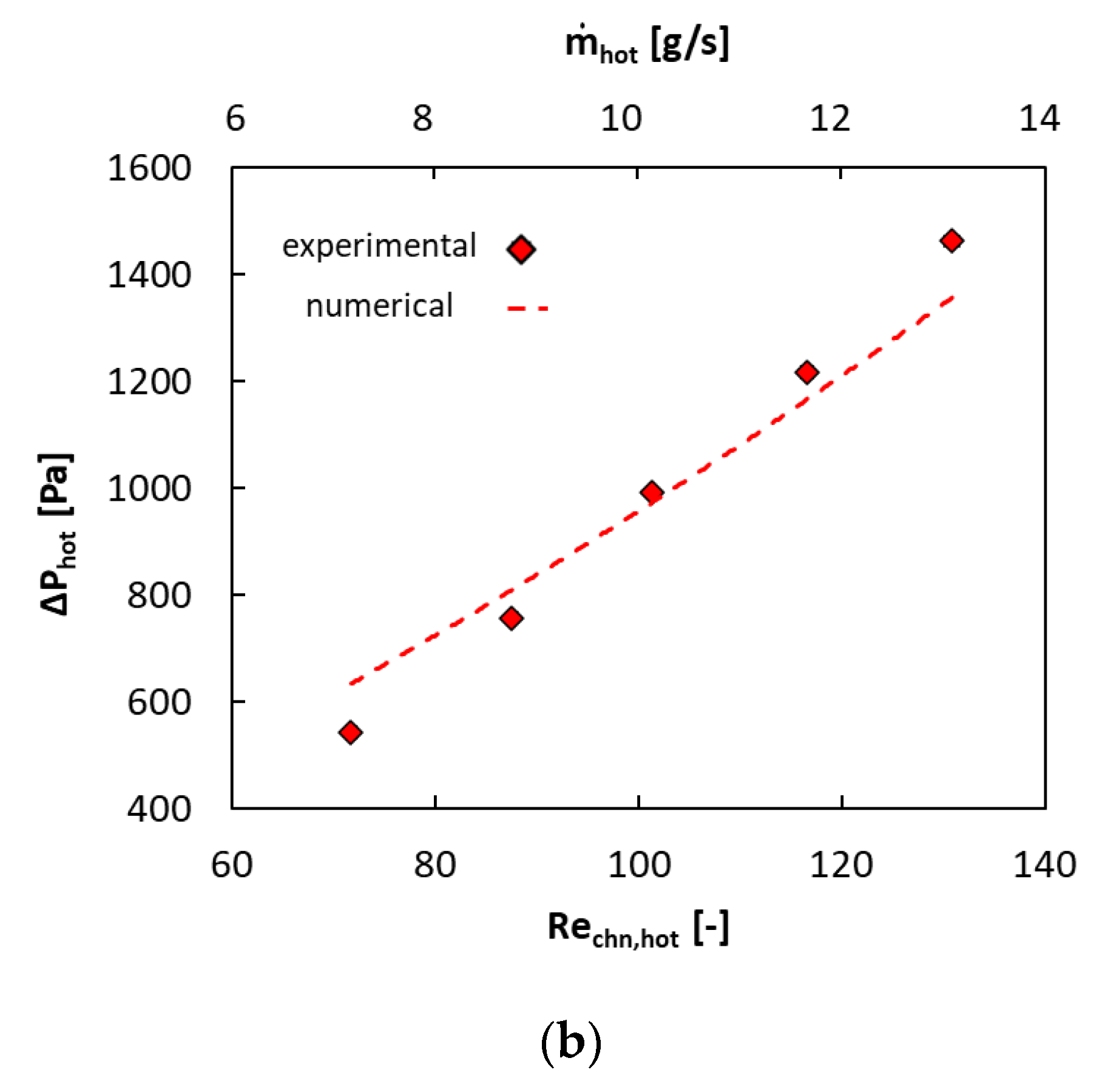
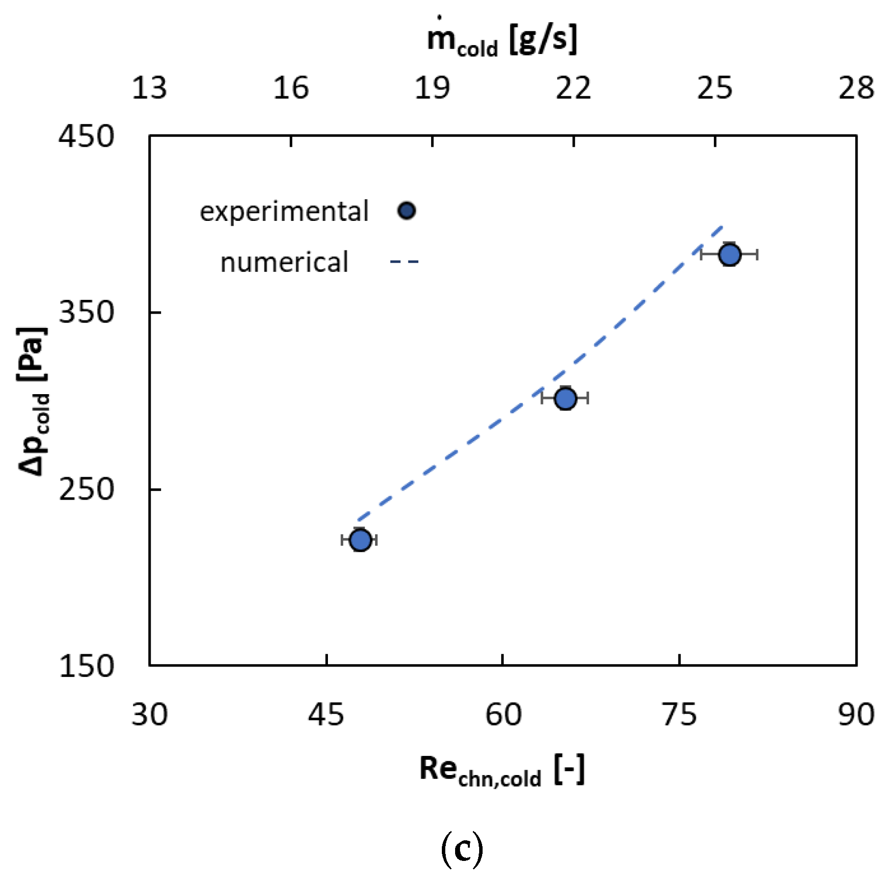
A comparison between the numerical and experimental results is presented in Figure 6. Compared to the numerical data (shown as dotted lines), the average percentage error between the numerical and experimental results was about 17% for the heat transfer performance (Figure 6a). For the pressure drops, the deviation between numerical and experimental was, on average, 9% and 4% for the hot (Figure 6b) and cold (Figure 6c) sides, respectively. The cause of this deviation could be predominantly due to the printing defects during the AM manufacturing process. For example, some leftover powder was observed to be blocking some of the microchannels, and a few damaged fins were detected in the CT scan images (see Ref. [39] for more details), as depicted in Figure 7, which are discussed next. A combination of these factors could explain the difference in the pressure drop results, as discussed in the next section.

6.4. Fabrication Quality Inspection

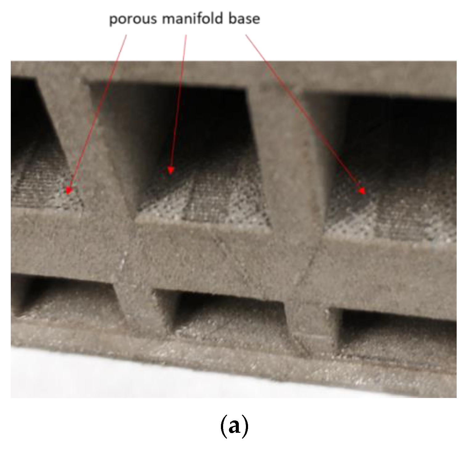
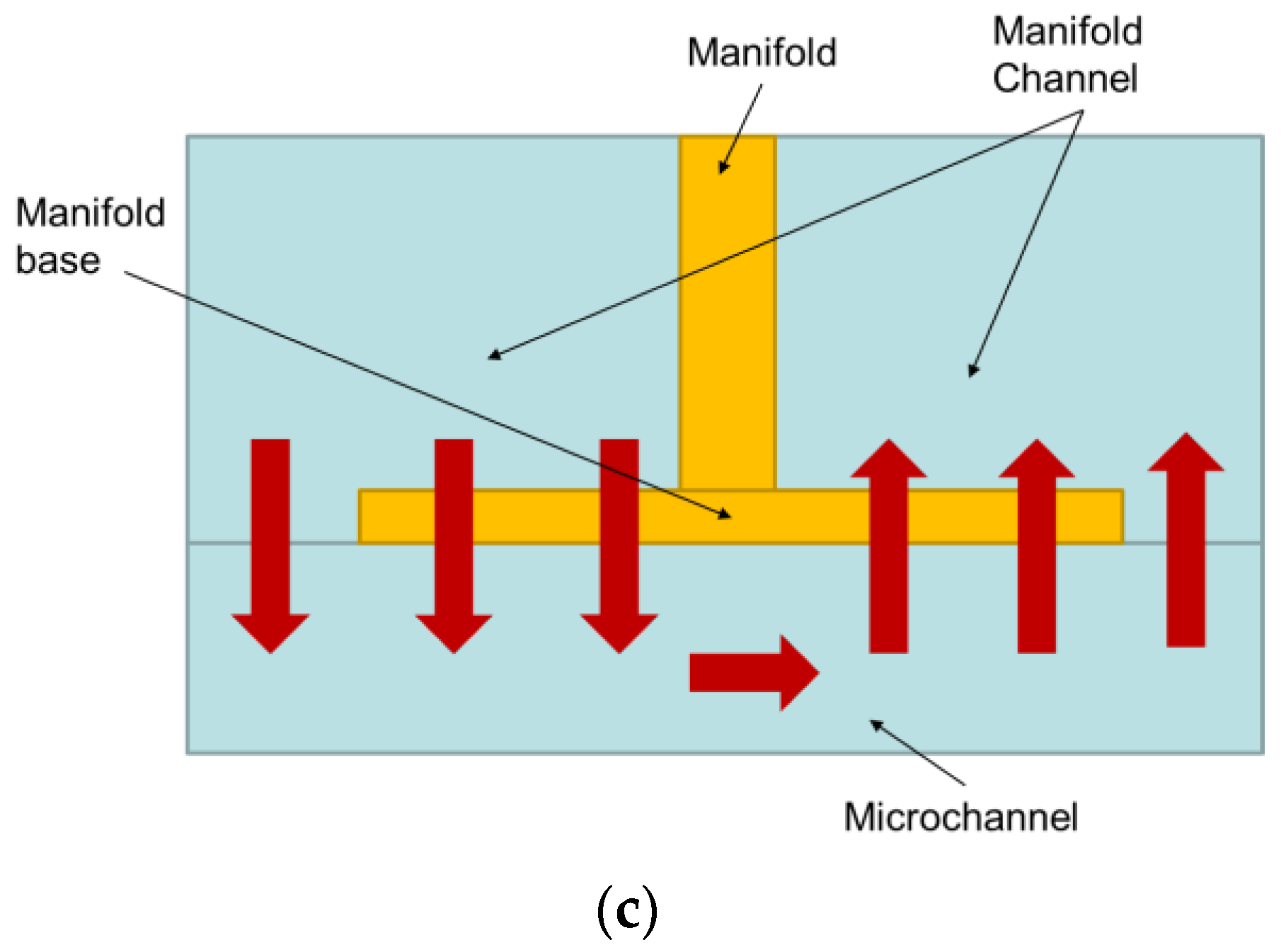
A possible cause for the deviation between the numerical and experimental data in the heat transfer performance (Figure 6a) could be the porous manifold base, as shown in Figure 7a. As shown in Figure 1, the manifold base was placed on top of the microchannel, which determined the flow length of the fluid in the microchannels, as shown in Figure 7b. It was desirable to have the manifold base as thin as possible to minimize its mass. However, a very thin manifold base may result in a porous structure that can alter the flow in the microchannel. The porosities in the manifold base caused a portion of the flow to take a shortcut path in the microchannels, as depicted in Figure 7c. This caused a portion of the heat transfer area to not be fully utilized, and the heat transfer performance was significantly reduced.

6.5. Comparison with State of the Art

To rate M2HXs against conventionally designed HXs, the experimental results obtained during the performance testing were compared with the performance of conventional HXs. Based on a database provided in Ref. [12], several commercially available PFHXs were selected, as shown in Table 5.
The sizing process was performed by matching the heat duty ( Q ), HX effectiveness ( ε ), coefficient of performance ( C O P ), and inlet temperature for both sides of the plate fin HXs to the corresponding values in the M2HX. The C O P was evaluated considering the pumping power on both sides of the HX as:
C O P = Q p t o t , h o t m ˙ h o t ρ h o t + p t o t , c o l d m ˙ c o l d ρ c o l d
where:
p t o t = ρ 2 v m n d 2 ( k c + 1 σ i n 2 ) E n t r a n c e p r e s s u r e   l o s s + f v c h m 2 L f l o w D H , c h n C o r e p r e s s u r e   l o s s + v m n d 2 ( 1 σ e x i t 2 k e ) E x i t p r e s s u r e   l o s s
where v m n d is the velocity in the manifold channel, k c is the coefficient of contraction, k e is the coefficient of expansion, and σ is the area ratio of the minimum free flow area over the frontal area. It must be noted that, as the cold-side loop was an open circuit with exit air facing the ambient, the coefficient of expansion was approximately one, and the exit area ratio ( σ e x i t ) was assumed to be 0. Thus, the exit pressure loss in Equation (13) was equal to zero. A more detailed description of the conventional surface geometries and the sizing method can be found in [43].
Figure 8 shows the performance comparison between M2HX and PFHXs in terms of the gravimetric heat transfer density ( Q / m T ) and volumetric heat transfer density ( Q / V T ) as a function of C O P , where m and V are the overall mass and volume of HX, while T is the temperature difference between the hot and cold inlet temperatures. As expected, increasing C O P decreased the heat transfer density because the smaller pressure drops negatively affected the heat transfer performance and the heat duty as a consequence. It was possible to see that for the same C O P , M2HX yielded a more than 60% improvement in both gravimetric heat transfer density ( Q / m T ) and volumetric heat transfer density ( Q / V T ) compared to PFHXs. When dealing with the aerospace industry, lightweight and compactness are vital for HXs to break into the market. These results show that despite fabrication imperfections, which reduce its performance, printed M2HX is still superior to conventional PFHXs, warranting further investment in this technology.

7. Conclusions

This work studied the feasibility of using additively manufactured manifold microchannel heat exchangers as a possible alternative for current gas-to-gas heat exchangers in high-temperature applications, such as the environmental control system for aircraft or other applications. For the first time, a manifold microchannel heat exchanger made out of Inconel 718 with straight fins on both sides, with an overall core size of 94 mm × 87.6 mm × 94.4 mm and a fin thickness of 0.220 mm, was successfully fabricated and tested. Although the HX was designed for operations at higher temperatures and pressures, limitations in our existing test loop allowed for testing only at 300 °C and 50 psia using N2 on the hot side and ambient air on the cold side. An overall heat transfer coefficient of 276 W/m2K for the heat exchanger was obtained: almost six times higher than that for shell and tube heat exchangers using air-to-air configurations for the same operating conditions. A coefficient of performance of up to 52 was also measured. Compared to the conventional plate-and-fin heat exchangers, up to 60% improvement in terms of gravimetric heat transfer density ( Q / m T ) and volumetric heat transfer density ( V / m T ) was observed for the same C O P . The same order of performance superiority was also observed when the manifold microchannel heat exchanger was compared with a state-of-the-art printed circuit heat exchanger.

Author Contributions

All the authors contributed to conceptualizing and implementing the research. F.B. created the first design, conducted the tests, and reduced the data. X.Z. provided input in the design and support in experiments. M.A. provided support in numerical modeling and fabrication. The work was performed under the guidance and supervision of M.O. and A.S. All authors have read and agreed to the published version of the manuscript.

Funding

This research was funded by the US Department of Energy, ARPA-E division, under subrecipient award DE-AR0000692, with Boeing Company as the prime recipient.

Data Availability Statement

The data are available on request.

Acknowledgments

The financial support of this work by the US Department of Energy, ARPA-E division, under subrecipient award DE-AR0000692 with Boeing Company as the prime recipient, is greatly acknowledged. The views and opinions of the authors expressed herein do not necessarily state or reflect those of the United States Government or any agency thereof. The authors wish in particular to thank ARPA-E Program Directors, David Tew, and Adison Stark and other ARPA-E staff, including Geoffrey Short, and Joel Fetter, all from ARPA-E, for their technical insight and advice over the course of this project. The authors also wish to thank Arun Muley, Michael Stoia, and Doug H. Van Affelen from Boeing Research & Technology for their support and feedback that positively affected the additive manufacturing effort under this project.

Conflicts of Interest

The authors declare no conflict of interest.

Nomenclature

A Area [m2]
C m a x Maximum heat capacity rate [W/K]
C m i n Minimum heat capacity rate [W/K]
c p Specific heat [J/kgK]
C r Heat capacity rates ratio [-]
C O P Coefficient of performance [-]
D H Hydraulic diameter [m]
f Friction factor [-]
H Height [m]
h Heat transfer coefficient [W/m2K]
k Thermal conductivity [W/mK]
k c Coefficient of constriction [-]
k e Coefficient of expansion [-]
L Length [m]
m Mass of the heat exchanger [kg]
m ˙ Mass flow rate [kg/s]
n Total number of microchannels per side in one stack [-]
N Total number of stacks [-]
N u Nusselt number [-]
p Pressure [Pa]
Δ p Pressure drop [Pa]
Q Heat duty of the heat exchanger [W]
Q / m T Gravimetric heat transfer density [W/kgK]
Q / V T Gravimetric heat transfer density [W/m3K]
R e Reynolds number [-]
U Overall heat transfer coefficient [W/m2K]
U n X Uncertainty of variable X
T Temperature [°C]
Δ T Temperature difference [°C]
t Thickness [m]
v Velocity [m/s]
V Volumetric [m3]
X Measured variables pertaining to calculated variable Y
W Width [m]
Y Calculated variable
ε Effectiveness [-]
μ Dynamic viscosity [Pa s]
η f i n Fin efficiency [-]
σ Area ratio of minimum free flow area to the frontal area [-]
ρ Density [kg/m3]
baseBase
chnMicrochannel
coldCold side
exitExit
finFin
flowAverage flow between the entrance and exit of the heat exchanger
hotHot side
inInlet
mndManifold
mnd-chnManifold channel
no-flowNo-flow direction
outOutlet
PCPrinted circuit heat exchanger
solidSolid part
stackStack
totTotal
AMAdditive Manufacturing
DMLSDirect Metal Laser Sintering
EBMElectron Beam Melting
ECSEnvironmental Control System
HPHigh Pressure
HTHigh Temperature
HTHPHXHigh-Temperature, High-Pressure Heat Exchanger
HTHXHigh-Temperature Heat Exchanger
HXHeat Exchanger
M2HXManifold Microchannel Heat Exchanger
MHXMicrochannel Heat Exchanger
PCHXPrinted Circuit Heat Exchanger
PFHXPlate-and-Fin Heat Exchanger
SiCSintered Silicon Carbide
SLMSelective Laser Melting

References

  1. Wright, S.; Andrews, G.; Sabir, H. A review of heat exchanger fouling in the context of aircraft air-conditioning systems, and the potential for electrostatic filtering. Appl. Therm. Eng. 2009, 29, 2596–2609. [Google Scholar] [CrossRef]
  2. Sundèn, B.; Fu, J. Heat Transfer in Aerospace Applications; Academic Press: Cambridge, MA, USA, 2017. [Google Scholar]
  3. Ashby, M.F. Materials Selection in Mechanical Design; Butterworth-Heinemann: Oxford, UK, 2005. [Google Scholar]
  4. Sommers, A.; Wang, Q.; Han, X.; T’Joen, C.; Park, Y.; Jacobi, A. Ceramics and ceramic matrix composites for heat exchangers in advanced thermal systems—A review. Appl. Therm. Eng. 2010, 30, 1277–1291. [Google Scholar] [CrossRef]
  5. Peterson, P.F.; Zhao, H.; Niu, F.; Huang, W.; Schmidt, J.; Schulte-Fischedick, J. Development of C-SiC Ceramic Compact Plate Heat Exchangers for High Temperature Heat Transfer Applications. In Proceedings of the Annual Meeting of the American Institute of Chemical Engineers, San Francisco, CA, USA, 12–17 November 2006; American Institute of Chemical Engineers: New York, NY, USA, 2006. [Google Scholar]
  6. Ohadi, M.M.; Buckley, S.G. High temperature heat exchangers and microscale combustion systems: Applications to thermal system miniaturization. Exp. Therm. Fluid Sci. 2001, 25, 207–217. [Google Scholar] [CrossRef]
  7. San Jose Delta Inc. Ceramics for Strength. Available online: https://www.sanjosedelta.com/ceramics_strength.html (accessed on 3 March 2020).
  8. Strumpf, H. High-Temperature Heat Exchangers for Aerospace Applications. In Proceedings of the ARPA-E High Intensity Thermal Exchange through Materials and Manufacturing Processes (HITEMMP) Kickoff Meeting; St. Louis, MO, USA, 16–17 October 2019. Available online: https://arpa-e.energy.gov/sites/default/files/DAY_I_02_IT_01_Hal_Strumpf.pdf (accessed on 7 September 2022).
  9. Shah, R.K. Compact Heat Exchangers for Microturbines. In Proceedings of the Fifth International Conference on Enhanced, Compact and Ultra-Compact Heat Exchangers: Science, Engineering and Technology, Whistler, BC, Canada, 11–16 September 2005; pp. 247–257. [Google Scholar]
  10. Dewson, S.; Li, X. Selection Criteria for the High Temperature Reactor Intermediate Heat Exchanger. In Proceedings of the ICAPP, Seoul, Republic of Korea, 15–19 May 2005; pp. 1–8. [Google Scholar]
  11. Subbaraman, G.; Kung, S.; Saari, H. Materials for Supercritical CO2 Applications a Tutorial. In Proceedings of the 6th International Supercritical CO2 Power Cycles Symposium, Pittsburgh, PA, USA, 27–29 March 2018. [Google Scholar]
  12. Kays, W.M.; London, A.L. Compact Heat Exchangers; McGraw-Hill: New York, NY, USA, 1984. [Google Scholar]
  13. Li, Q.; Flamant, G.; Yuan, X.; Neveu, P.; Luo, L. Compact heat exchangers: A review and future applications for a new generation of high temperature solar receivers. Renew. Sustain. Energy Rev. 2011, 15, 4855–4875. [Google Scholar] [CrossRef]
  14. Ismail, L.S.; Velraj, R.; Ranganayakulu, C. Studies on pumping power in terms of pressure drop and heat transfer characteristics of compact plate-fin heat exchangers—A review. Renew. Sustain. Energy Rev. 2010, 14, 478–485. [Google Scholar] [CrossRef]
  15. Strumpf, H.; Mirza, Z. Development of a Microchannel Heat Exchanger for Aerospace Applications. In Proceedings of the ASME 2012 10th International Conference on Nanochannels, Microchannels, and Minichannels, Rio Grande, PR, USA, 8–12 July 2012; p. 459. [Google Scholar] [CrossRef]
  16. Chen, M.; Sun, X.; Christensen, R.N.; Skavdahl, I.; Utgikar, V.; Sabharwall, P. Pressure drop and heat transfer characteristics of a high-temperature printed circuit heat exchanger. Appl. Therm. Eng. 2016, 108, 1409–1417. [Google Scholar] [CrossRef]
  17. Chen, M.; Sun, X.; Christensen, R.N.; Skavdahl, I.; Utgikar, V.; Sabharwall, P. Dynamic behavior of a high-temperature printed circuit heat exchanger: Numerical modeling and experimental investigation. Appl. Therm. Eng. 2018, 135, 246–256. [Google Scholar] [CrossRef]
  18. Mylavarapu, S.; Sun, X.; Figley, J.; Needler, N.; Christensen, R. Investigation of High-Temperature Printed Circuit Heat Ex-changers for Very High Temperature Reactors. J. Eng. Gas Turbines Power 2009, 131, 62905. [Google Scholar] [CrossRef]
  19. Fan, Y.; Luo, L. Recent Applications of Advances in Microchannel Heat Exchangers and Multi-Scale Design Optimization. Heat Transf. Eng. 2008, 29, 461–474. [Google Scholar] [CrossRef]
  20. Kanlayasiri, K.; Paul, B. A Nickel Aluminide Microchannel Array Heat Exchanger for High-Temperature Applications. J. Manuf. Process. 2004, 6, 72–80. [Google Scholar] [CrossRef]
  21. Jafari, D.; Wits, W.W. The utilization of selective laser melting technology on heat transfer devices for thermal energy conversion applications: A review. Renew. Sustain. Energy Rev. 2018, 91, 420–442. [Google Scholar] [CrossRef]
  22. Ohadi, M.; Zhang, X.; Keramati, H.; Arie, M.; Singer, F.; Tiwari, R.; Shooshtari, A. Recent developments in high temperature heat exchangers: A review. Front. Heat Mass Transf. 2018, 11. [Google Scholar] [CrossRef]
  23. Battaglia, F.; Singer, F.; Dessiatoun, S.V.; Ohadi, M.M. Comparison of Near Source Two-Phase Flow Cooling of Power Electronics in Thermosiphon and Forced Convection Modes. In Proceedings of the 2017 16th IEEE Intersociety Conference on Thermal and Thermomechanical Phenomena in Electronic Systems (ITherm), Orlando, FL, USA, 30 May–2 June 2017; pp. 752–758. [Google Scholar] [CrossRef]
  24. Zhang, X.; Tiwari, R.; Shooshtari, A.H.; Ohadi, M.M. An additively manufactured metallic manifold-microchannel heat exchanger for high temperature applications. Appl. Therm. Eng. 2018, 143, 899–908. [Google Scholar] [CrossRef]
  25. Arie, M.A.; Shooshtari, A.H.; Ohadi, M.M. Experimental characterization of an additively manufactured heat exchanger for dry cooling of power plants. Appl. Therm. Eng. 2018, 129, 187–198. [Google Scholar] [CrossRef]
  26. Collins, I.L.; Weibel, J.A.; Pan, L.; Garimella, S.V. Evaluation of Additively Manufactured Microchannel Heat Sinks. IEEE Trans. Compon. Packag. Manuf. Technol. 2019, 9, 446–457. [Google Scholar] [CrossRef]
  27. Romei, F.; Grubišić, A.N.; Gibbon, D. Manufacturing of a high-temperature resistojet heat exchanger by selective laser melting. Acta Astronaut. 2017, 138, 356–368. [Google Scholar] [CrossRef]
  28. Hathaway, B.J.; Garde, K.; Mantell, S.C.; Davidson, J.H. Design and characterization of an additive manufactured hydraulic oil cooler. Int. J. Heat Mass Transf. 2018, 117, 188–200. [Google Scholar] [CrossRef]
  29. Arie, M.A.; Shooshtari, A.; Ohadi, M. Air Side Enhancement of Heat Transfer in an Additively Manufactured 1 kW Heat Exchanger for Dry Cooling Applications. In Proceedings of the 2017 16th IEEE Intersociety Conference on Thermal and Thermomechanical Phenomena in Electronic Systems (ITherm), Orlando, FL, USA, 30 May–2 June 2017; pp. 1–8. [Google Scholar] [CrossRef]
  30. Gerstler, W.D.; Erno, D. Introduction of an Additively Manufactured Multifurcating Heat Exchanger. In Proceedings of the 2017 16th IEEE Intersociety Conference on Thermal and Thermomechanical Phenomena in Electronic Systems (ITherm), Orlando, FL, USA, 30 May–2 June 2017; pp. 624–633. [Google Scholar]
  31. Gerstler, W.D.; Erno, D.J.; Kenworthy, M.T.; Rambo, J.D.; Sabo, N.K. Heat Exchanger Including Furcating Unit Cells, 22-Mar-2016. Application No. 15077191. U.S. Patent 10739077, 11 August 2020. [Google Scholar]
  32. Bacellar, D.; Aute, V.; Huang, Z.; Radermacher, R. Design optimization and validation of high-performance heat exchangers using approximation assisted optimization and additive manufacturing. Sci. Technol. Built Environ. 2017, 23, 896–911. [Google Scholar] [CrossRef]
  33. Thompson, S.M.; Aspin, Z.S.; Shamsaei, N.; Elwany, A.; Bian, L. Additive manufacturing of heat exchangers: A case study on a multi-layered Ti6Al4V oscillating heat pipe. Addit. Manuf. 2015, 8, 163–174. [Google Scholar] [CrossRef]
  34. Cormier, Y.; Dupuis, P.; Farjam, A.; Corbeil, A.; Jodoin, B. Additive manufacturing of pyramidal pin fins: Height and fin density effects under forced convection. Int. J. Heat Mass Transf. 2014, 75, 235–244. [Google Scholar] [CrossRef]
  35. Hutter, C.; Büchi, D.; Zuber, V.; von Rohr, P.R. Heat transfer in metal foams and designed porous media. Chem. Eng. Sci. 2011, 66, 3806–3814. [Google Scholar] [CrossRef]
  36. Tsopanos, S.; Sutcliffe, C.J.; Owen, I. The Manufacture of Micro Cross-Flow Heat Exchangers by Selective Laser Melting. In Proceedings of the Fifth International Conference on Enhanced, Compact and Ultra-Compact Heat Exchanger, Science, Engineering and Technology, Whistler, BC, Canada, 11–16 September 2005. [Google Scholar]
  37. Arie, M.A.; Shooshtari, A.H.; Rao, V.V.; Dessiatoun, S.V.; Ohadi, M.M. Air-Side Heat Transfer Enhancement Utilizing Design Optimization and an Additive Manufacturing Technique. J. Heat Transf. 2016, 139, 31901. [Google Scholar] [CrossRef]
  38. Zhang, X.; Singer, F.; Shooshtari, A.H.; Ohadi, M.M. Impact of Additive Manufacturing on Performance Enhancement of Heat Exchangers: A Case Study on An Air-To-Air Heat Exchanger for High Temperature Applications. In Proceedings of the International Heat Transfer Conference Digital Library, Beijing, China, 10–15 August 2018. [Google Scholar] [CrossRef]
  39. Battaglia, F.; Zhang, X.; Arie, M.A.; Shooshtari, A.; Sarmiento, A.; Ohadi, M. Additive Manufacturing of a High Temperature, Ni-Based Superalloy Compact Heat Exchanger: A Study on the Role of Select Key Printing Parameters. J. Heat Transf. 2023, 145, 41901. [Google Scholar] [CrossRef]
  40. Nellis, G.; Klein, S.A. Heat Transfer; Cambridge University Press: Cambridge, UK, 2009. [Google Scholar]
  41. Taylor, B.N.; Kuyatt, C.E. Guidelines for Evaluating and Expressing the Uncertainty of NIST Measurement Results. 1994. Available online: https://emtoolbox.nist.gov/publications/nisttechnicalnote1297s.pdf (accessed on 22 July 2022).
  42. Engineering Page > Heat Exchangers > Typical Overall Heat Transfer Coefficients. Available online: http://www.engineeringpage.com/technology/thermal/transfer.html (accessed on 18 February 2020).
  43. Arie, A.; Shooshtari, A.H.; Dessiatoun, S.V.; Al-Hajri, E.; Ohadi, M.M. Numerical modeling and thermal optimization of a sin-gle-phase flow manifold-microchannel plate heat exchanger. Int. J. Heat Mass Transf. 2015, 81, 478–489. [Google Scholar] [CrossRef]
  44. Mandel, R.; Arie, M.; Shooshtari, A.; Ohadi, M. A Heat Spreading Model for Double-Sided, Cross-Flow, Manifold-Microchannel Heat Exchangers. In Proceedings of the 2018 17th IEEE Intersociety Conference on Thermal and Thermomechanical Phenomena in Electronic Systems (ITherm), San Diego, CA, USA, 29 May–1 January 2018; pp. 147–155. [Google Scholar] [CrossRef]
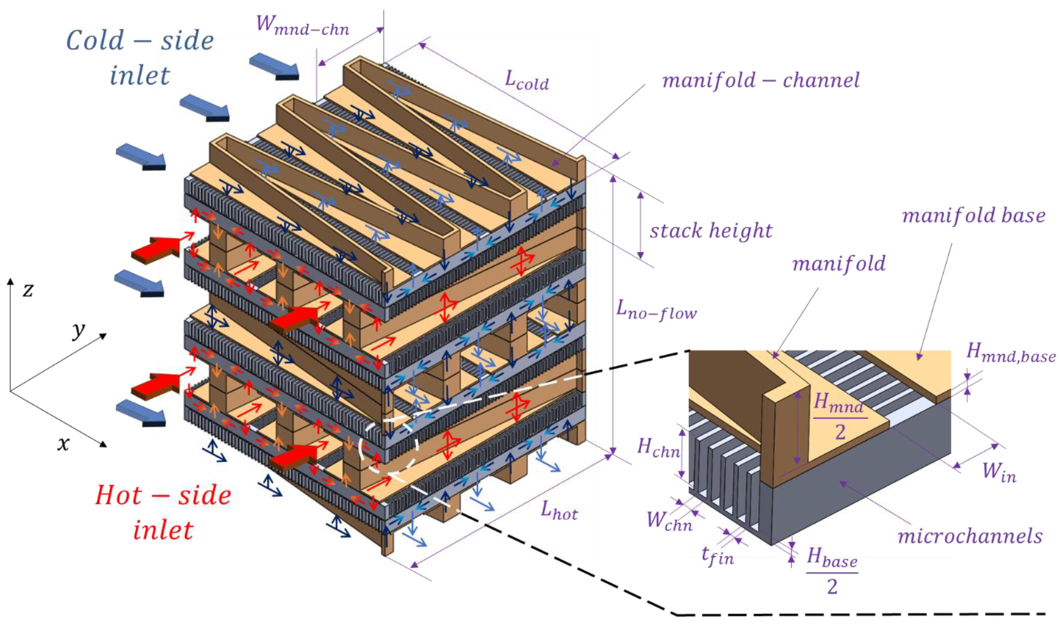
Figure 1. Schematic diagram of M2HX (not to scale).
Energies 16 04156 g001
Figure 2. Fabricated M2HX: (a) Heat exchanger core; (b) Welded heat exchanger core with headers.
Energies 16 04156 g002
Figure 3. Experimental setup schematic diagram.
Energies 16 04156 g003
Figure 4. Heat transfer performance results: (a) Effectiveness of the HX (Equation (11)), (b) Heat duty, (c) Overall heat transfer coefficient.
Energies 16 04156 g004aEnergies 16 04156 g004b
Figure 5. Pressure drop results: (a) Hot-side pressure drop and friction factor; (b) Cold-side pressure drop and friction factor.
Energies 16 04156 g005
Figure 6. Comparison between experimental and numerical results: (a) Heat flow rate; (b) Hot-side pressure drop, (c) Cold-side pressure drop.
Energies 16 04156 g006aEnergies 16 04156 g006bEnergies 16 04156 g006c
Figure 7. (a) Porous manifold base picture from the HX. (b) Flow direction in the microchannels with a solid manifold base—no shortcut flow. (c) Flow direction in the microchannels with a porous manifold base—with shortcut flow.
Energies 16 04156 g007aEnergies 16 04156 g007bEnergies 16 04156 g007c
Figure 8. Performance comparison between M2HX with plate HXs.
Energies 16 04156 g008
Table 1. A review of the literature on the use of additive manufacturing in the production of heat exchangers.
AuthorAM TechDesignMaterialReported Outcome
Zhang et al., 2018 [24]DMLSManifold-microchannel on both sidesInconel 718Up to 25% improvement in heat transfer density compared to conventional PFHXs
Arie et al., 2018 [25]DMLSAir side: manifold-microchannel;
Water side: rectangular channel
3 HXs:
-
SS17-4
-
Ti64
-
AlSi10Mg
Compared to wavy fin and plain plate fin HXs, they showed up to 30% and 40% improvement, respectively, in gravimetric heat transfer density
Collins et al., 2018 [26]DMLSStraight and manifold microchannel heat sinkAlSi10MgManifold reduces the pressure drop by 40–90% compared to a straight microchannel
Romei et al., 2017 [27]SLMRecirculating flow HX316 LFine structures with feature sizes below 200 μm
Hathaway et al., 2017 [28]SLMPlate-fin
tube
AlSi10 MgCapability to additively manufacture commercial-scale HXs with a feature resolution of 500 μm
Arie et al., 2017 [29]DMLSAir side: manifold-microchannel
Water side: rectangular channel
Ti64Up to 190% improvement in air-side heat transfer coefficients compared to conventional
PFHXs
Gerstler and Erno, 2017 [30]SLMHX with furcating unit cells [31]4 HXs:
-
Aluminum
-
Ti 6-4
-
Cobalt chrome
-
Inconel 718
AM design has equivalent heat transfer and pressure drop to the conventional HX while having 66% lower weight and 50% lower volume
Bacellar et al., 2017 [32]DMLSNovel fin-and-airfoil tubeTitanium grade 5Optimum designs achieve more than a 50% reduction in size, material, and pressure drop compared to the baseline microchannel heat exchanger
Thompson et al., 2015 [33]SLMFlat-plate oscillating heat pipeTi–6Al–4VFlat-plate oscillating heat pipe with 1.53-mm diameter channel
Cormier et al., 2014 [34]Cold spray technologyPyramidal pin finsAl6061 T6The investigation concentrated on samples with fin densities of 12 fins per inch between 1.0 and 2.2 mm height and samples of 1.0 mm height with fin densities varying between 12 and 24 fins per inch
Hutter et al., 2011 [35]DMLSMetal foamsHigh alloyed steelComparison of commercial metal foam with the designed porous media realized by the AM method led up to a 40% improvement in heat transfer
Tsopanos et al., 2009 [36]SLMMicro cross-flow HX with rectangular channels on both sides316 LAM provided a channel range of 150–170 microns and roughness Ra of 15 microns
Table 2. Heat exchanger geometrical parameters.
Hot-Side
H c h n 0.900 mm
t f i n 0.220 mm
W c h n 0.180 mm
W i n / W m n d c h n 0.086
n 219
H b a s e 0.500 mm
Cold-Side
H c h n 1.20 mm
t f i n 0.220 mm
W c h n 0.180 mm
W i n / W m n d c h n 0.43
n 235
H b a s e 0.500 mm
Overall Size
L c o l d 0.094 m
L h o t 0.0876 m
L n o f l o w 0.0944 m
N 8
Table 3. Experimental test conditions.
Temperature, Pressure, and Mass Flow Rate Boundary Conditions
T i n , c o l d 25 °C
T i n , h o t 300 °C
p h o t 340 kPa
p c o l d 101 kPa
m ˙ c o l d 15, 20, 25 g/s
m ˙ h o t 7–13 g/s
Table 4. List of measurement equipment and its accuracy.
Equipment FunctionEquipment NameAccuracy
Hot-side flow rateCoriolis flow meter
(0.5-inch size)
±0.5% of the measurement
Cold-side flow rateCoriolis flow meter
(1-inch size)
±3% of the measurement
TemperatureK type thermocouple±2.2 °C or 0.75% of the measurement
Hot-side pressure dropPressure transducer±0.25% FS of 5.5 kPa
Cold-side pressure dropPressure transducer±0.25% FS of 5.5 kPa
Table 5. Key geometrical specification of the conventional PFHX surface [12].
NameFin Pitch [fin/cm]Plate Spacing (cm)
S1027T4.041.38
S14775.820.838
S11104.370.635
S15085.941.06
Disclaimer/Publisher’s Note: The statements, opinions and data contained in all publications are solely those of the individual author(s) and contributor(s) and not of MDPI and/or the editor(s). MDPI and/or the editor(s) disclaim responsibility for any injury to people or property resulting from any ideas, methods, instructions or products referred to in the content.