Abstract
This paper presents a novel design approach of a Petri-net-based cyber-physical system (CPS). The idea is oriented toward implementation in a field-programmable gate array (FPGA). The proposed technique permits error detection in the system at the early specification stage in order to reduce the time and prototyping cost of the CPS. Due to the state explosion problem, the traditional verification methods have exponential computational complexity. In contrast, we show that under certain assumptions, the proposed algorithm is able to detect possible errors in the system even in cubic O() time. Furthermore, all the required steps of the proposed design method are presented and discussed. The idea is illustrated by a real-life case study example of a traffic light crossroad. The system was modelled, analysed, implemented, and finally validated within the FPGA device (Virtex-5 family).
1. Introduction
A Petri net is an effective modelling tool that permits the graphical specification of control systems [1,2,3,4,5,6]. It is supported by verification, validation, and analysis methods; thus, the designer is able to verify the robustness and reliability of the prototyped system at the very early design stage [5,7,8]. The flexibility, usefulness, and wide possibilities of formal verification methods related to the Petri-net-based systems have made them very popular in specification of control systems in various fields of human life, such as manufacturing systems [9,10,11,12], cyber-physical systems [13], work-flow management [14], embedded software [15], logic controllers [16], transportation and vehicular systems, military, smart buildings and smart grids, power electronics converters, etc. [1,5,17].
A Petri-net-based approach benefits from the verification of the system at the early specification stage, which allows a reduction in time and costs of the modelled system [18,19,20,21]. The key properties of Petri-net-based systems to be examined are boundedness [3,5,7,12,18], safeness [12,22,23,24,25], and absence of deadlocks [24,26]. A bounded Petri net assures that the model has a finite number of reachable states of the system [24,27]. Safeness supplies a binary behaviour of a Petri net dedicated to the logical control of systems [22,25,28]. Furthermore, the lack of deadlock means that the system will not get jammed in one state, and it will be always possible to reach the desired next states [29].
Petri nets are especially useful in specification of concurrent control systems [30]. Furthermore, their concurrent nature is essential at the implementation stage of the modelled system to hardware that supports parallelism [3,4,5,31]. A field-programmable gate array (FPGA) is one of the targets for the concurrent systems specified by a Petri net [5,13,32,33]. Such devices are parallel by their architecture [5,34]. Their main advantages rely on the matrix of programmable logic blocks, which is a part of FPGA device [35]. This benefit results in the high performance, flexibility, and the possibility of dynamic reconfiguration (modification of the structure during runtime of the device) [36,37,38,39].
Moving on to the analysis aspects of Petri-net-based systems, there are two immensely popular techniques that allow examination of the system properties [7,22,27,40]. The first one is based on the reachability tree exploration [26,40], while the other one utilizes linear algebra methodology by computing place invariants [6,41,42]. Unfortunately, both methods have serious limitations, related to the state explosion problem. Indeed, the number of reachable states (invariants) can be exponential [4,5,7]. This results in the exponential computational complexity of the algorithm, which means that the solution may not be found within the assumed time [24].
Besides the typical design aspects, in this paper we will also focus on the boundedness examination of the system. Let us now briefly underline the role of boundedness in the hardware-oriented systems modelled with Petri nets. Such ideas are considered in [5,15,43]. The system is initially specified by an interpreted Petri net, an extension of the ordinary Petri net containing additional binary inputs and outputs of the modelled controller [44]. One of the crucial properties that is required in order to design a CPS with an interpreted Petri net is boundedness. A bounded system guarantees the finite number of reachable states, which is especially important in case of further implementation in the FPGA. Therefore, the modelled system ought to be verified against the unbounded places. It should be underlined that such an examination can be carried out at the early design stage. Once the system is verified, it can be prototyped in the hardware description languages (Verilog, VHDL) [30]. Finally, it is implemented with the reconfigurable devices (e.g., FPGA).
Recently, the idea of so-called dynamic partial reconfiguration of an FPGA has become very popular [16,17]. This approach permits the replacement of a portion of the already implemented system without stopping the already-programmed device. To perform the dynamic partial reconfiguration, the system ought to be properly designed (for example, decomposed into static and dynamic parts), and synchronized. Such operations can be performed with the use of interpreted nets. Let us underline that the presented Petri-net-based reconfigurable techniques require on their input systems that are bounded and free from deadlocks.
In [45], a Petri-net-based approach oriented toward implementation in the FPGAs is shown. The algorithm is supported by a case study example of direct matrix converters. However, differing from the previously described papers, the detailed design flow is presented. The solution deals with the verification techniques of the control part of the Petri-net-based cyber-physical system. Moreover, analysis methods, simulation and hardware validation are described. Nevertheless, the presented descriptions are very general. The authors do not include algorithms that permit boundedness analysis, nor hardware description language templates for realization of the system within FPGA. Moreover, the proposed technique is directly oriented towards realization of the direct matrix converters.
Finally, let us recall Petri-net-based models that are directly oriented on the specification of the cyber-physical systems (CPS). Such a system combines computation with physical routes. The behaviour of a CPS is generally split into two parts: cyber and physical parts. Specification of the control part of the CPS by a Petri net is shown in [13]. In particular, the paper proposes Petri-net-based design of a CPS oriented to control direct matrix converter with space vector modulator. The control algorithm is initially described by a deadlock-free and 1-bounded (safe) Petri net and is oriented toward hardware implementation in the FPGA device. However, the detailed verification algorithms are not considered, nor presented in the paper.
To summarize the above discussion, it can be noticed that there are several problems related to the designing of the Petri-net-based CPS aimed at the implementation in FPGAs. First, there is no comprehensive framework for designing such systems, that includes modelling, verification, and hardware implementation aspects. Another problem is related to the analysis of the key properties of the Petri-net-based system (e.g., boundedness). The computational complexity of the existing techniques is usually exponential [3,4,5,6,7]. This means that the result of analysis may be not achieved within the assumed time [5]. Considering that the current design solutions require bounded (and/or safe) Petri nets, this may cause serious problems for the designers. Finally, the existing design techniques are rather oriented on the particular solution (e.g., direct matrix converter). Therefore, there is a need to develop a comprehensive design framework that includes all the above aspects.
This paper proposes a novel design and analysis technique of cyber-physical systems for implementation in the FPGA. The idea is based on the interpreted Petri nets; thus, it is mainly oriented toward cyber-physical systems. Nevertheless, let us point out that any concurrent system that applies the proposed rules can be designed and analysed. Furthermore, a novel verification method of a Petri-net-based CPS is proposed. The algorithm permits the detection of possible unbounded places in the system. Contrary to the existing solutions, which are mainly exponential, the proposed idea permits performing the verification process in polynomial time (note that this paper is directly focused on the formal verification techniques and, thus, it does not deal with the security aspects of CPS, those can be found in other works, e.g., [46,47,48,49,50]). Finally, the transformation of the Petri-net-based model to the hardware is proposed and presented in detail. The main contributions of the paper can be summarized as follows:
- The comprehensive design flow of the cyber-physical systems modelled by an interpreted Petri net is proposed. The presented design flow is aimed mainly at (but not restricted to) the implementation of the CPS in the FPGA device. The presented methodology includes all necessary steps, including modelling of the system by an interpreted Petri net, formal verification, transformation to the hardware description, and final implementation in the FPGA.
- Besides the complete design flow, a novel verification algorithm is introduced. The method allows the initial error checking in order to obtain potentially unbounded places. The main advantage of the proposed method is its polynomial computational complexity. It is proved that the algorithm runs in time.
- The presented design flow, as well as proposed verification technique are illustrated by a real-life cyber-physical system. In particular, a traffic light controller is designed and implemented within FPGA. The system was additionally validated in hardware with the use of the miniaturization model of the crossroad traffic light system.
The paper is structured as follows. Section 2 presents the foundational definitions and notations. The proposed design method with analysis algorithms is included within Section 3. Section 4 illustrates the presented approach by a real-life case study example. Finally, Section 5 summarizes the discussion and presents directions for future research.
2. Basic Notations and Definitions
Definition 1.
A Petri net is a four-tuple:, where: is a set of places, is a set of transitions, is a set of arcs, is an initial marking.
A State of a Petri net is called marking, denoted by . Marking is a subset of Petri net places . A marked place contains a token (or tokens).
A transition is enabled if all its input places contain a token. A transition is fired if and only if it is enabled.
Definition 2.
A Petri net is bounded if the number of tokens in every place does not exceed a finite number for any marking reachable from . A Petri net that is bounded for any finite initial marking is said to be structurally bounded.
Definition 3.
A Petri net is safe if it is 1-bounded.
Definition 4.
A Petri net is live if it is possible to fire any transition from any reachable marking (by a sequence of firings of other transitions).
Definition 5.
An interpreted Petri net is a bounded and live Petri net that is defined as a six-tuple: . Here, denotes the set of binary inputs, while denotes the set of binary outputs of the CPS.
Note that several notations of the interpreted Petri nets can be found in the literature. In this paper, we assume that the interpreted Petri net specifies a cyber-physical system, and it is bounded and live.
Note that in the case of interpreted Petri nets, there is an additional condition for transition firing. In an interpreted Petri net, a transition is fired if and only if it is enabled and all its associated input values (from the set ) are fulfilled.
Definition 6.
An incidence matrix of an interpreted Petri net is a matrix of integers, given by:
A cell of the matrix refers to transition and place . The columns of the matrix correspond to places, while the rows refer to transitions of the interpreted Petri net. Matrix (or just ) means its transposed form.
Definition 7.
A place invariant (p-invariant) of an interpreted Petri net is a -vector of integers such that . The set of places corresponding to nonzero entries in a p-invariant is called support of a place invariant.
Definition 8.
An interpreted Petri net is covered by p-invariants if every place belongs to at least one support of a p-invariant.
Theorem 1
[51]. An interpreted Petri net is structurally bounded if it is covered by place invariants.
Definition 9.
Amatrixis in the reduced row echelon form (RREF) if and only if:
- (a)
- Any rows consisting entirely of zeros are grouped together at the bottom of the matrix; otherwise, the first nonzero number in the row is 1 (leading one);
- (b)
- Each column of the matrix containing a leading one has zeros everywhere else;
- (c)
- In any two successive nonzero rows of the matrix, the leading one in the lower row occurs farther to the right than the leading one in the higher row.
Definition 10.
A single leading one of a matrix in the reduced row echelon form denotes an entry, where all the remaining entries of row are equal to zero.
3. The Proposed Design and Verification Techniques
The proposed design technique is strictly oriented toward implementation of the system within the FPGA. It consists of all necessary steps, starting from the modelling of the CPS by a Petri net, its formal analysis, as well as further transformation of the model to the hardware description languages, and final realization in the physical device. Beside the comprehensive design flow, a novel verification idea is proposed. The method permits detecting possible errors (unbounded places) in a polynomial time.
In general, the proposed design technique consists of four main steps:
- Modelling of the system by an interpreted Petri net.
- Formal verification of the system (detection of possible unbounded places).
- Hardware modelling of the system (transformation to HDL description).
- Implementation and validation of the system within FPGA.
Let us now describe each of the above steps in more detail.
3.1. Modelling of the System by an Interpreted Petri Net
Initially, based on the informal description of the system (e.g., given by the customer), the formal specification of the CPS is prepared. The cyber-physical system is modelled by an interpreted Petri net, considering all its properties. The main advantage of Petri-net-based design is the relatively easy description of concurrent processes that occur in the system. Moreover, graphical representation can be very helpful during meetings between the customer and designers in order to understand the meaning and final product to be achieved. What is important is that interpreted nets enhance the traditional (classical) class of Petri nets through—among others—additional input and output signals. They are, in general, used for communication of the system with the environment but can be also applied in modelling aspects. One of the most popular problems that may occur during specification of the system by a Petri net is conflicts. A conflict refers to the situation, where more than one transition is enabled (and thus can be fired) at the same time.
Consider an exemplary CPS shown in Figure 1. There are three places and four transitions in the net, while is initially marked. The model presented in the left (a) is specified by an ordinary (pure, classical) Petri net. In such a description, the behaviour of the system is not determined since both transitions and are enabled and can be fired. This situation is called conflict. One of the possibilities for conflict resolution is modification of the Petri net structure [52]. This obviously requires additional actions from the designers, which is time- and cost-consuming. Another possibility for conflict resolution is the application of interpreted Petri nets. The extension of the system is assumed from input and output signals, as presented in Figure 1b. The additional internal signal sun resolves conflict in the system: when it is active (binary equal to “1”), then transition is enabled and can be fired. Otherwise, in the situation where sun is not active (equal to “0”), transition is enabled. Note that the CPS shown in Figure 1b reflects the real-life situation. Depending on the daylight level, the light (associated with the place ) is turned on or off. The adequate decision is made based on the sensor (represented in the system by the signal sun).
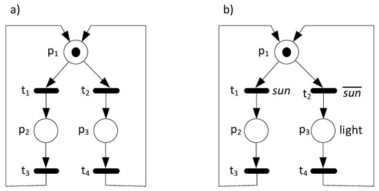
Figure 1.
A Petri-net-based system with conflict (a), and its possible resolution (b).
Moving on to the detailed modelling necessities, according to the definition of the interpreted Petri net, the modelled system ought to be live and bounded (or even safe). In this paper we focus on the boundedness aspects of the designed system. Such a property is especially crucial in case of the further implementation of the system in the hardware. In order to avoid unexpected (unwanted) states (which may result in the unstable functionality of the system in the FPGA), the CPS ought to be bounded (or at least examined against the possible unbounded places).
Obviously, the designers usually try to keep in mind such requirements during modelling of the system. There are several useful modelling tools that support analysis and verification of the system at the specification stage, e.g., PIPE (Platform Independent Petri net Editor 2) [53] or IOPT-Tools (Input-Output Place-Transition-Tools) [54]. Nevertheless, especially in the case of complicated models, it is extremely hard to examine the system and detect possible mistakes. Although modelling tools are supported by the verification (and even validation) techniques, very often it is not possible to analyse the system due to the state explosion problem [22,24,25,27,55,56]. The traditional, commonly used methods are exponential; thus, searching for the result may take a long time, or they may not even be found.
In this paper, a novel verification technique of the Petri-net-based CPS is proposed. The method is aimed at the detection of possible unbounded places in the system. The main advantage of the presented algorithm is its polynomial (cubic) computational complexity. Contrary to the existing methods, the method is not restricted to the particular class of Petri net [57,58,59,60]. However, there are also limitations, which we will discuss later in this paper.
3.2. Formal Verification of the System (Detection of Possible Unbounded Places)
The proposed verification idea is based on the linear algebra technique, and it takes into account the existence of the place invariant covering in the net. According to the Theorem 1, the Petri net is structurally bounded if it is covered by place invariants. We will apply this important property to the examination of the system. However, in contrast to the existing methods, we will not compute the complete (or even reduced) set of place invariants. The concept is based on the transformation of the interpreted Petri net incidence matrix to the reduced row echelon form, and its further analysis. The proposed verification technique is illustrated by Algorithm 1.
| Algorithm 1: Searching for possible unbounded places in the Petri-net-based CPS | |
| 1. | Read incidence matrix of interpreted Petri net . |
| 2. | Transformation of : |
| for each row | |
| find row with the leftmost nonzero entry ; | |
| swap rows and ; | |
| divide row by | |
| for each : | |
| for each : | |
| ; | |
| end for | |
| end for | |
| end for | |
| 3. | Examination of the transformed matrix: |
| set ; | |
| set ; | |
| for each row : | |
| while ( and ): | |
| ++; | |
| end while | |
| if () break; | |
| for (: | |
| if (: | |
| :=; | |
| end if | |
| end for | |
| end for | |
| 4. | Print the possible unbounded places and return the algorithm: |
| if (): | |
| print No unbounded places found! | |
| else | |
| print The possible unbounded places in the CPS: | |
| for each place | |
| print ; | |
| end for | |
| end if | |
| return . | |
The presented algorithm permits finding the possible unbounded places in the analysed CPS. It is assumed that the system is represented by an incidence matrix, directly according to Definition 6. Therefore, columns of the matrix correspond to places of the Petri net, while rows refer to transitions. At the subsequent step, transformations of the initial matrix are executed. In particular, the reduced row echelon form is achieved. In particular, the presented algorithm applies the Gauss–Jordan reduction technique [61]. The third step is the crucial point of the proposed algorithm. The reduced matrix is examined according to the presence of the place invariant covering. According to Theorem 1, the existence of such a cover assures that the Petri net is structurally bounded. Therefore, if the particular place is not included in any p-invariant, it is considered to be possibly unbounded. Finally, the fourth step reports the results and prints possible unbounded places (if any).
The main advantage of the presented algorithm is its computational complexity, which is polynomial. It should be noted that this refers to all classes of Petri nets. This is a huge benefit in comparison to the existing methods, which are exponential (except particular narrowed classes of Petri nets, as shown in [62,63,64]). On the other hand, there is also an important limitation of the proposed method. The technique permits determining whether the system is covered by place invariants and detecting particular places that are not included in such a cover. However, we are not sure whether the particular place is unbounded or not. Nevertheless, such an examination is relatively easy to execute, through, for example, the simulation of the system. Once the designer has some knowledge about potentially unbounded places, the particular areas of the system can be carefully checked through validation of the CPS.
Let us now formulate the adequate propositions and prove them formally. Firstly, we show that existence of the single leading one in the matrix indicates that the corresponding place is not covered by any place invariant, and, hence, it might be unbounded. Furthermore, we will prove that the proposed algorithm is bounded by a polynomial (in the number of transitions and places of the Petri net).
Proposition 1.
Let be an incidence matrix in the reduced row echelon form of an interpreted Petri net that specifies the cyber-physical system. If there exists a single leading one in this matrix, then the corresponding place is not covered by any p-invariant, and thus it might be unbounded.
Proof.
Assume that there exists a row of the matrix that specifies the cyber-physical system as containing only a single leading one at entry . From Definition 9 (point b), we know that each column of the matrix containing a leading one has zeros everywhere else. Moreover, from Definition 10, we also know all the remaining entries of a row containing a single leading one are also equal to zero. Clearly, there does not exist any place invariant that solves the linear equation such that the support of contains . Hence, is not covered by any place invariant. Furthermore, from Theorem 1 we know that the interpreted Petri net is structurally bounded if it is covered by place invariants. Since is not covered by any place invariant, we do not know whether is bounded, and thus place might be unbounded. □
Proposition 2.
The computational complexity of Algorithm 1 isbounded by O(), where denotes the number of places, and denotes the number of transitions in the interpreted Petri net.
Proof.
The presented algorithm is divided into four main parts. The first and the last (fourth) parts read input values and outputs results; thus, we will not consider them in the complexity estimation. The second part involves three nested loops. Two of them are executed on the set of transitions, while the third (the inner one) involves the set of places. Thus, the computational complexity of this step is bounded by O(). Furthermore, the third step involves searching for leading ones in the matrix, which is executed at most O() times (note that the number of rows of the reduced matrix corresponds to the number of transitions in the initial interpreted Petri net). Therefore, the total computational complexity of Algorithm 1 is bounded by a cubic O() with the number of places and transitions. □
Once the set of possible unbounded places is obtained, the designer is able to detect and correct errors. In general, the revision of the interpreted Petri net is strictly related to the functionality of the modelled CPS. However, there are several known mistakes that can be easily resolved; let us briefly present one of the most common.
Figure 2a shows an exemplary CPS where the fork–join split was used improperly. This fault caused by the designers is related to the improper splitting and joining of places/transitions. The initial process is split into two subprocesses by transition . This means that places and are executed concurrently. The further firing of transitions and leads to the situation where two tokens can be accumulated by place . Hence, this place is unbounded. Obviously, such a mistake was caused by improper splitting (or joining) of the processes. Note that such an error may lead to the unexpected states in the system, where two or more places are simultaneously executed instead of one.
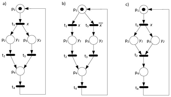
Figure 2.
An unbounded CPS (fork-join) (a), and its corrected: 1st version (b), and 2nd version (c).
Figure 2b presents one of the possible solutions. This one is based on the single sequential process. An additional transition was added in order to revise the modelled CPS. Now, all places are bounded; thus, the system is correctly specified. Note that the revised version of the system includes conflict (caused by newly added transition ); thus, input signal was applied to resolve it. Alternatively, the presented CPS can be corrected as shown in Figure 2c. Although there exist two concurrent subprocesses in the system, they are properly merged by transition .
3.3. Hardware Modelling of the System (Transformation to HDL Description)
Once the CPS is modelled and verified, it can be described in the hardware description language (HDL) toward implementation in the FPGA. This is a hardware model of the system, and it directly refers to the Petri-net-based specification. In this paper, we will follow the behavioural description of the CPS in the Verilog language, initially shown in [30]. The HDL model contains three main parts that reflect the behaviour of the interpreted Petri-net-based system. They directly refer to the description of places, transitions, and output signals. It is also assumed that the system is synchronous, that is, oscillated by the clock signal (i.e., provided by an FPGA). Let us explain the hardware model using an example. Recall the CPS shown in Figure 1b. The hardware model of this system is presented in Listing 1. Initially, the general description of the Verilog module is created. It contains a declaration of input and output signals, as specified by the Verilog standards [65].
| Listing 1. The HDL description of the system shown in Figure 1b. |
 |
In the presented example, there is one output signal (denoted by light), and three input signals: sun, clk, and reset. Note that two last signals are required due to the FPGA demands and style of proposed implementation (synchronous system). Furthermore, there are places and transitions declared as registers and wires, respectively. Let us discuss them.
The behaviour of the system is considered as synchronous; thus, it is described by the procedural always block. Switching between states (markings) is activated by the rising clock signal. Moreover, the asynchronous reset signal is provided. The presented procedural block directly specifies the behaviour of the CPS. Note that, additionally, keeping up the system in a particular state is also considered.
The second part describes the transitions. This block is performed with the use of continuous assignments. Each transition is reflected by the combination of related places and input signals. Recall the conflict described earlier (Section 3.1) in this paper. It is easily resolved by the external signal sun (lines 12, and 13). Two remaining transitions ( and ) are just triggered by places ( and , respectively).
Finally, the third part describes the output signals of the system. The particular outputs are set according to the specification of the CPS by the interpreted Petri net. In the presented example, there is only one output signal (light), which is active once the system reaches place (). The association is performed by the continuous assignment, as presented in line 21.
3.4. Implementation and Validation of the System within FPGA
The next step of the proposed design flow refers to the implementation of the CPS in the FPGA. This step can be generally divided into two substages. The first one is aimed at the logical synthesis and logical implementation of the system, while the second is directly related to the realization within the physical device. There are several FPGA vendors in the market [66,67,68,69]. Therefore, although the general concept is similar, the implementation can be slightly different. In this paper, we will follow the guidelines provided by Xilinx [70].
Moving on to the logic synthesis, this operation translates the Verilog description to the gate-level representation. Further logic implementation adjusts and maps the system to the particular hardware device. As the output of the above processes, the configuration bit-stream file is created. It is used for the physical realization of the system.
The physical implementation is performed by programming of the FPGA with the achieved bit-stream file. The data are sent via programming interfaces. This operation is usually fully controlled by the vendors’ tools.
Finally, once the system is physically implemented within the FPGA, it can be validated (simulated) at the hardware level. There are several ways to perform such an operation. The basic one is based on the oscilloscope and observation of the behaviour of the system. In particular, based on the assumed stimulus (input signals), the outputs are measured [13,45,71,72]. Obviously, such a technique may be awkward, especially in the case of more complex design. The other possibility is validation of the system in the real environment, with the application of the physical part of the CPS. It can be also carried out with the use of, e.g., miniaturization models of the prototyped system. We will present such a real validation later in this paper (cf. Section 4.4). Note that hardware validation of the system permits examination of the CPS in the real-life environment. However, it does not guarantee the proper functionality of the CPS, since there still can be unexpected or unreachable states in the system. Therefore, let us once more underline the important role of the formal verification proposed in Section 3.2.
4. Case Study Example
This section illustrates the proposed design technique with an example of a Petri-net-based CPS. Figure 3 shows a real-life crossroad traffic light system. There are four roads; each has three independent lines for cars (left, straight, and right), and two additional ones for pedestrians. The main benefit of the presented system is controlling the flexibility of the lights, including various situations, e.g., traffic intensity. Depending on the needs, several scenarios can be applied, including priority for cars (to reduce the traffic), for pedestrians (more strict rules for cars), or to make a collision-free crossroad.
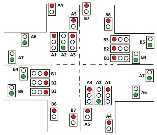
Figure 3.
The idea of a crossroad traffic light system.
The purpose of this case study is to present the design flow step by step, together with the application of the proposed verification techniques. Let us underline that the presented concept comes from real life and represents a crossroad traffic light system in Zielona Góra (Poland). Moreover, to validate the functionality of the system, the miniaturization model of the system was prepared (c.f. Section 4.4).
4.1. Modelling of the Crossroad Example by an Interpreted Petri Net
In the first phase of the system design, a formal specification is prepared based on the collected assumptions (illustrated in Figure 3). It is assumed that the modelled crossroad system is collision-free. In addition, on each road, there are dedicated pedestrian crossings controlled by two lights (red or green).
In the presented example, the crossroad is split into two main parts: part A and part B. The first one controls the upper-left and bottom-right corners of the crossroad. Those corners work in the same way (therefore, they are inverted vertically and horizontally in Figure 3). Similarly, part B controls the bottom-left and upper-right corners of the crossroad.
The traffic lights are numbered and prefixed by the part number and followed by the first letter of a particular signal colour (R—red, Y—yellow, G—green). For example, the traffic light signals for the cars coming from the north (up) and turning right are denoted by A1R (red), A1Y (yellow), and A1G (green); the light signals for cars going straight are denoted by A2R (red), A2Y (yellow), A2G (green), etc. Similarly, the traffic light signals for the pedestrians crossing the left side of the upper road are denoted by A4R (red), A4G (green) and A5R (red), A5G (green), etc. Each light can be controlled independently; thus, there are in total 17 traffic light signals on each part of the crossroad, denoted by A1R to A7G and B1R to B7G. For example, the red light of the traffic controller A1 (turning right for cars) is denoted by A1R, the green light of this controller by A1G, and yellow by A1Y. Similarly, the red light of A4 (pedestrians) is denoted by A4R, while the green light by A4G, etc.
Figure 4 shows the interpreted Petri net that specifies the presented traffic light system. There are thirty-two places and twelve transitions. Moreover, there are thirty-four output signals that control the traffic lights (they are assigned to particular places). The model of the system was prepared within the PIPE tool (v.4.3.0). For more readability, the Petri net shown in Figure 4 was prepared with the graphics software (Visio). To underline the meaning of particular place, the net was coloured adequately to the active output signals (red, yellow, and green).
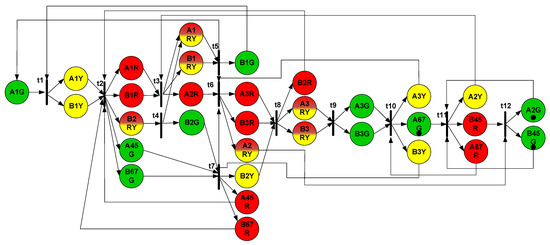
Figure 4.
The initial specification of the crossroad traffic light system.
Table 1 shows the association between places and outputs in the system. If more than one output is assigned to a given place (e.g., A1YR), it means that they are active simultaneously (at the same time). Note that the presented Petri net does not include any input signals; it is assumed that switching between states (markings) is oscillated by a clock signal (it will be applied during the hardware-modelling stage, c.f. Section 4.3).

Table 1.
Association between places and output signals.
4.2. Formal Verification of the System (Detection of Possible Unbounded Places)
Once the system is formally specified by an interpreted Petri net, it can be formally verified against the possible errors and mistakes. Since the specification was prepared within PIPE, this tool was initially used to perform the analysis. The results of the tool showed that the modelled Petri net did not contain deadlocks, but it was not bounded. This means that advanced verification (and/or validation) was required in order to obtain the unbounded places. Unfortunately, the traditional verification based on the place invariant analysis (performed with the classical method shown in [6], as well as executed with the analysis tool that is available within PIPE) was completed with no success due to the exponential explosion of place invariants (the configuration of the applied computer: Intel Core i9-9900K CPU @ 3.60GHz, 128 GB RAM, the termination time was set to 300,000 ms).
Since the traditional algorithm failed to verify the system, Algorithm 1 was applied to examine the presented system. The initial incidence matrix was of size (thirty-two places and twelve transitions). After the verification, the algorithm determined that there was one possible unbounded place in the system: A1YR. Indeed, this place accumulates tokens infinitely, and the behaviour of the traffic light system can be unpredictable. This may lead to dangerous situations in real life, and the system ought to be corrected. It can be easily observed that tokens are accumulated after firing transition or transition . Obviously, this is a designer’s mistake since it was not intended to turn on the yellow and red signals of the A1 signal-head, right after the red and yellow signals of the B2 become inactive. This mistake might be solved by removing the arc leading from transition to place A1YR. Finally, let us underline that the run-time of Algorithm 1 was just only 1.17 ms, while the traditional algorithm was not able to complete the task.
The corrected CPS is shown in Figure 5. The system was examined once more. This time PIPE indicated that the net was bounded (and even safe). Moreover, Algorithm 1 confirmed that no possible unbounded places were found in the revised interpreted Petri net. This means that no formal mistakes were found, and the design flow could proceed.
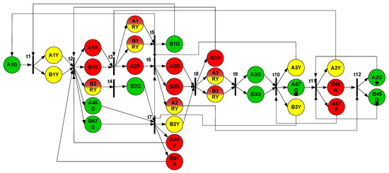
Figure 5.
Corrected (final) specification of the crossroad traffic light system.
4.3. Hardware Modelling of the System (Transformation to HDL Description)
After the formal verification, the interpreted Petri net model was transformed into the HDL description. The hardware description of the crossroad traffic light system was prepared exactly according to the rules presented in Section 3.3. Listing 2 shows the Verilog module of the designed CPS.
The name of the module was set to Crossroad _FPGA. The list of input and output ports include clock and reset signals, as well as all outputs of the traffic light system. Note that the presented listing contains only parts of the code; the list of output signals is also truncated. There are thirty-two registers declared for representation of particular places. They are merged within the 32-bit vector p. Furthermore, twelve wire signals are used in order to declare transitions. Those signals are combined within the 12-bit vector t.
Moving on to the description of the functionality of the system, two types of assignments were used. Switching between states (markings) of the CPS are executed by the synchronous always block. It is triggered by the positive edge of the clock signal (denoted by clk). There is also the reset signal which is considered. In contrast to the clock signal, reset is asynchronous; thus, the system can be zeroed any time it is needed. The transitions are described by continuous assignments. Note that such assignments refer to the enabled transitions, while firing is executed by the always block.
Finally, the output signals are associated with places by the continuous assignments. Note that several output signals are associated with the same place. For example, outputs B6R and B7R are assigned to p [32] (which refers to the place B67R denoted in Figure 4).
| Listing 2. The HDL description of the system shown in Figure 5. |
 |
4.4. Implementation and Validation of the System within FPGA
The last step of the presented design flow refers to the logical and psychical implementation of the CPS in the FPGA device. Firstly, the HDL model is synthesized in order to obtain a gate-level representation. This is a low-level description of the traffic light controller. Adjusting the system to the particular FPGA is executed during the logic implementation. The presented case study example was physically implemented within the Xilinx xc5vlx50-2ff676 device from the Virtex-5 family.
Logic synthesis and implementation resulted in no errors, nor were any warnings detected. The summary utilization of the FPGA device is shown in Figure 6. The implemented crossroad traffic light system consumed 116 look-up tables (LUTs) and 59 registers (Flip Flops). This resulted in 49 occupied Slices of the device. It should be underlined that this is just a fraction (1%) of the available resources.
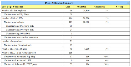
Figure 6.
FPGA utilization summary.
Finally, the bit-stream was generated. This file was used during the physical implementation of the system in the FPGA device. The hardware validation of the designed CPS was performed with the use of the miniaturization model of the crossroad traffic light system. Figure 7 shows such a miniaturization model of the traffic light controller during the validation process.
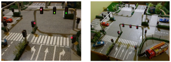
Figure 7.
The miniaturization model of the traffic light controller.
The hardware examination of the system confirmed the design assumptions. Moreover, the hardware simulation permitted validating the already-implemented traffic light controller in the real-life environment with the miniaturization model. Nevertheless, let us once more underline the importance of the formal verification process presented in step 4.2. Thanks to the detection of unbounded places, the designed CPS was corrected at the early prototyping stage, before the transformation of the model to the HDL code, logic synthesis and implementation, and the physical realization of the system in the FPGA device.
5. Conclusions
The complete design flow and novel verification technique of the Petri-net-based cyber-physical systems were proposed in the paper. The methodology is oriented toward the implementation of the CPS in the FPGA device. Besides the comprehensive prototyping methodology, a verification algorithm of the possible unbounded places was introduced.
The main benefit of the proposed method is polynomial computational complexity. Contrary to the popular analysis techniques, the presented approach does not require computation of all place invariants which are bounded exponentially in general. The idea is based on the transformation of the incidence matrix of the interpreted Petri net, and examination of the system in terms of place invariant coverage. It is proved that the algorithm runs in cubic time.
The proposed design flow was illustrated by a real-life cyber-physical system. The exemplary traffic light controller was modelled, verified, described in hardware, and finally implemented in the FPGA device. Moreover, a miniaturization of the crossroad traffic lights was prepared in order to validate and visualise the functionality of the CPS.
Moving on to the limitations of the proposed techniques, one may say that the presented algorithm indicates the possible unbounded places. Indeed, the method does not guarantee that the detected place is truly unbounded. According to the presented theorems, there is still a possibility that although such a place is not included in the place invariant coverage, it can be bounded. Nevertheless, let us point out that the main problem of such a complicated CPS relies on the indication of possible errors and mistakes. Once the designer obtains the possible doubtful area (e.g., possible unbounded places), the functionality of the system can be relatively easily validated. Additionally, preliminary research indicates that such a situation (where indicated places are not bounded) is rather rare. More detailed research in this direction is planned for future works.
Finally, future works include further enhancement of the presented verification technique. The authors observed that besides the information about boundedness, the proposed method, in certain cases, can be also used in order to examine the absence of deadlocks. Furthermore, it is planned to perform the detailed examination of the proposed verification algorithm. In particular, the collection of representative benchmarks (about 250) will be applied in order to verify the efficiency and effectiveness of the method. Moreover, it is planned to develop additional examination methods of the detected places in order to verify their boundedness.
Author Contributions
Conceptualization, R.W. and M.W.; Formal analysis, R.W. and M.W.; Funding acquisition, R.W.; Investigation, R.W. and M.W.; Methodology, R.W. and M.W.; Project administration, R.W.; Resources, R.W.; Software, R.W.; Supervision, R.W. and Z.L.; Validation, R.W.; Visualization, M.W.; Writing—original draft, R.W. and M.W.; Writing—review and editing, R.W., M.W. and Z.L. All authors have read and agreed to the published version of the manuscript.
Funding
This research is supported by NATIONAL SCIENCE CENTRE, POLAND, grant number 2019/35/B/ST6/01683. The APC was funded by R. Wisniewski.
Data Availability Statement
Not applicable.
Conflicts of Interest
The authors declare no conflict of interest.
References
- Clempner, J. An Analytical Method for Well-Formed Workflow/Petri Net Verification of Classical Soundness. Int. J. Appl. Math. Comput. Sci. 2014, 24, 931–939. [Google Scholar] [CrossRef]
- Gu, C.; Ma, Z.; Li, Z.; Giua, A. Verification of Nonblockingness in Bounded Petri Nets With a Semi-Structural Approach. In Proceedings of the 2019 IEEE 58th Conference on Decision and Control (CDC), Nice, France, 11–13 December 2019; IEEE: Piscataway, NJ, USA, 2019; pp. 6718–6723. [Google Scholar]
- Girault, C.; Valk, R. Petri Nets for Systems Engineering: A Guide to Modeling, Verification, and Applications; Springer: Berlin/Heidelberg, Germany, 2003; ISBN 978-3-540-41217-5. [Google Scholar]
- Murata, T. Petri Nets: Properties, Analysis and Applications. Proc. IEEE 1989, 77, 541–580. [Google Scholar] [CrossRef]
- Wiśniewski, R. Prototyping of Concurrent Control Systems Implemented in FPGA Devices; Advances in Industrial Control; Springer International Publishing: Berlin/Heidelberg, Germany, 2017; ISBN 978-3-319-45810-6. [Google Scholar]
- Martínez, J.; Silva, M. A Simple and Fast Algorithm to Obtain All Invariants of a Generalised Petri Net. In Proceedings of the Application and Theory of Petri Nets; Girault, C., Reisig, W., Eds.; Springer: Berlin, Heidelberg, 1982; pp. 301–310. [Google Scholar]
- Karatkevich, A. Dynamic Analysis of Petri Net-Based Discrete Systems; Lecture Notes in Control and Information Sciences; Springer: Berlin/Heidelberg, Germany, 2007; ISBN 978-3-540-71464-4. [Google Scholar]
- Zhou, M.; Wu, N. System Modeling and Control with Resource-Oriented Petri Nets, 1st ed.; CRC Press: Boca Raton, FL, USA, 2009; ISBN 978-1-4398-0884-9. [Google Scholar]
- Koh, I.; DiCesare, F. Transformation Methods for Generalized Petri Nets and Their Applications to Flexible Manufacturing Systems. In Proceedings of the 1990 Rensselaer’s Second International Conference on Computer Integrated Manufacturing, Troy, NY, USA, 21–23 May 1990; pp. 364–371. [Google Scholar]
- Kaid, H.; Al-Ahmari, A.; Li, Z.; Davidrajuh, R. Automatic Supervisory Controller for Deadlock Control in Reconfigurable Manufacturing Systems with Dynamic Changes. Appl. Sci. 2020, 10, 5270. [Google Scholar] [CrossRef]
- Patalas-Maliszewska, J.; Wiśniewski, R.; Topczak, M.; Wojnakowski, M. Modelling of the Effectiveness of Integrating Additive Manufacturing Technologies into Petri Net-Based Manufacturing Systems. In Proceedings of the 2022 IEEE International Conference on Fuzzy Systems (FUZZ-IEEE), Padua, Italy, 18–23 July 2022; IEEE: Piscataway, NJ, USA, 2022; pp. 1–9. [Google Scholar]
- Patalas-Maliszewska, J.; Wiśniewski, R.; Topczak, M.; Wojnakowski, M. Design Optimization of the Petri Net-Based Production Process Supported by Additive Manufacturing Technologies. Bull. Pol. Acad. Sci. Tech. Sci. 2022, 70, e140693. [Google Scholar]
- Wiśniewski, R.; Bazydło, G.; Szcześniak, P.; Wojnakowski, M. Petri Net-Based Specification of Cyber-Physical Systems Oriented to Control Direct Matrix Converters With Space Vector Modulation. IEEE Access 2019, 7, 23407–23420. [Google Scholar] [CrossRef]
- van der Aalst, W.M.P. Workflow Verification: Finding Control-Flow Errors Using Petri-Net-Based Techniques. In Business Process Management: Models, Techniques, and Empirical Studies; van der Aalst, W., Desel, J., Oberweis, A., Eds.; Lecture Notes in Computer Science; Springer: Berlin/Heidelberg, Germany, 2000; pp. 161–183. ISBN 978-3-540-45594-3. [Google Scholar]
- Yakovlev, A.; Gomes, L.; Lavagno, L. (Eds.) Hardware Design and Petri Nets; Springer: New York, NY, USA, 2000; ISBN 978-0-7923-7791-7. [Google Scholar]
- Alcaraz, M.; Campos-Rodriguez, R.; Lopez-Mellado, E.; Ramirez-Trevino, A. Partial Reconfiguration of Control Systems Using Petri Nets Structural Redundancy. Inf. Technol. Control 2015, 44, 287–301. [Google Scholar] [CrossRef]
- Wiśniewski, R. Dynamic Partial Reconfiguration of Concurrent Control Systems Specified by Petri Nets and Implemented in Xilinx FPGA Devices. IEEE Access 2018, 6, 32376–32391. [Google Scholar] [CrossRef]
- Li, B.; Khlif-Bouassida, M.; Toguyéni, A. On–The–Fly Diagnosability Analysis of Bounded and Unbounded Labeled Petri Nets Using Verifier Nets. Int. J. Appl. Math. Comput. Sci. 2018, 28, 269–281. [Google Scholar] [CrossRef]
- Szpyrka, M.; Biernacka, A.; Biernacki, J. Methods of Translation of Petri Nets to NuSMV Language. In Proceedings of the CS&P, Chemnitz, Germany, 29 September–1 October 2014. [Google Scholar]
- van der Aalst, W.M.P.; van Hee, K.M.; ter Hofstede, A.H.M.; Sidorova, N.; Verbeek, H.M.W.; Voorhoeve, M.; Wynn, M.T. Soundness of Workflow Nets: Classification, Decidability, and Analysis. Form. Asp. Comput. 2011, 23, 333–363. [Google Scholar] [CrossRef]
- Zaitsev, D. Clans of Petri Nets: Verification of Protocols and Performance Evaluation of Networks; LAP LAMBERT Academic Publishing: London, UK, 2013; ISBN 978-3-659-42228-7. [Google Scholar]
- Wojnakowski, M.; Wiśniewski, R.; Bazydło, G.; Popławski, M. Analysis of Safeness in a Petri Net-Based Specification of the Control Part of Cyber-Physical Systems. Appl. Math. Comput. Sci. 2021, 31, 647–657. [Google Scholar] [CrossRef]
- Ide, K.; Wasaki, K. Efficient Algorithm for Liveness/Safeness Analysis of Free-Choice Nets in a Petri Net Tool: HiPS. In Proceedings of the 2012 6th International Conference on New Trends in Information Science, Service Science and Data Mining (ISSDM2012), Taipei, Taiwan, 23–25 October 2012; IEEE: Piscataway, NJ, USA, 2012; pp. 179–184. [Google Scholar]
- Wojnakowski, M.; Popławski, M.; Wiśniewski, R.; Bazydło, G. Hippo-CPS: Verification of Boundedness, Safeness and Liveness of Petri Net-Based Cyber-Physical Systems. In Proceedings of the Technological Innovation for Digitalization and Virtualization; Camarinha-Matos, L.M., Ed.; Springer International Publishing: Cham, Switzerland, 2022; pp. 74–82. [Google Scholar]
- Wojnakowski, M.; Popławski, M.; Wiśniewski, R.; Bazydło, G. Safeness Analysis of Petri Net-Based Cyber-Physical Systems Based on the Linear Algebra and Parallel Reductions. In Proceedings of the AIP Conference Proceedings, Heraklion, Greece, 7 September 2021. [Google Scholar]
- Popławski, M.; Wojnakowski, M.; Bazydło, G.; Wiśniewski, R. Reachability Tree in Liveness Analysis of Petri Net-Based Cyber-Physical Systems. In Proceedings of the AIP Conference Proceedings, Heraklion, Greece, 7 September 2021. [Google Scholar]
- Wojnakowski, M.; Wiśniewski, R. Verification of the Boundedness Property in a Petri Net-Based Specification of the Control Part of Cyber-Physical Systems. In Proceedings of the Technological Innovation for Applied AI Systems; Camarinha-Matos, L.M., Ferreira, P., Brito, G., Eds.; Springer International Publishing: Cham, Switzerland, 2021; pp. 83–91. [Google Scholar]
- Wisniewski, R.; Wojnakowski, M.; Stefanowicz, Ł. Safety Analysis of Petri Nets Based on the SM-Cover Computed with the Linear Algebra Technique. AIP Conf. Proc. 2018, 2040, 080008. [Google Scholar] [CrossRef]
- Wojnakowski, M.; Wiśniewski, R.; Popławski, M. Bounded and Place Invariant-Covered Petri Nets for Cyber-Physical Systems Specification. In Proceedings of the AIP Conference Proceedings, Heraklion, Crete, Greece, 26–29 October 2022; AIP: New York, NY, USA, 2022. [Google Scholar]
- Wiśniewski, R. Design of Petri Net-Based Cyber-Physical Systems Oriented on the Implementation in Field Programmable Gate Arrays. Energies 2021, 14, 7054. [Google Scholar] [CrossRef]
- Reisig, W. Petri Nets: An Introduction; Monographs in Theoretical Computer Science: An EATCS Series; Springer: Berlin/Heidelberg, Germany, 1985; ISBN 978-3-642-69970-2. [Google Scholar]
- Ajao, L.A.; Agajo, J.; Umar, B.U.; Agboade, T.T.; Adegboye, M.A. Modeling and Implementation of Smart Home and Self-Control Window Using FPGA and Petri Net. In Proceedings of the 2020 IEEE PES/IAS PowerAfrica, Nairobi, Kenya, 25–28 August 2020; IEEE: Piscataway, NJ, USA, 2020; pp. 1–5. [Google Scholar]
- Costa, A.; Gomes, L.; Barros, J.P.; Oliveira, J.; Reis, T. Petri Nets Tools Framework Supporting FPGA-Based Controller Implementations. In Proceedings of the 2008 34th Annual Conference of IEEE Industrial Electronics, Orlando, FL, USA, 10–13 November 2008; IEEE: Piscataway, NJ, USA, 2008; pp. 2477–2482. [Google Scholar]
- Abughalieh, K.M.; Alawneh, S.G. A Survey of Parallel Implementations for Model Predictive Control. IEEE Access 2019, 7, 34348–34360. [Google Scholar] [CrossRef]
- Kubica, M.; Opara, A.; Kania, D. Technology Mapping for LUT-Based FPGA; Lecture Notes in Electrical Engineering; Springer International Publishing: Cham, Switzerland, 2021; Volume 713, ISBN 978-3-030-60487-5. [Google Scholar]
- Loschi, H.; Lezynski, P.; Smolenski, R.; Nascimento, D.; Sleszynski, W. FPGA-Based System for Electromagnetic Interference Evaluation in Random Modulated DC/DC Converters. Energies 2020, 13, 2389. [Google Scholar] [CrossRef]
- Marguč, J.; Truntič, M.; Rodič, M.; Milanovič, M. FPGA Based Real-Time Emulation System for Power Electronics Converters. Energies 2019, 12, 969. [Google Scholar] [CrossRef]
- Wiśniewski, R.; Bazydło, G.; Gomes, L.; Costa, A. Dynamic Partial Reconfiguration of Concurrent Control Systems Implemented in FPGA Devices. IEEE Trans. Ind. Inform. 2017, 13, 1734–1741. [Google Scholar] [CrossRef]
- Barkalov, A.; Titarenko, L.; Mielcarek, K. Improving Characteristics of LUT-Based Mealy FSMs. Int. J. Appl. Math. Comput. Sci. 2020, 30, 745–759. [Google Scholar] [CrossRef]
- Reisig, W. Nets Consisting of Places and Transistions. In Petri Nets: An Introduction; Reisig, W., Ed.; EATCS Monographs on Theoretical Computer Science; Springer: Berlin/Heidelberg, Germany, 1985; pp. 62–76. ISBN 978-3-642-69968-9. [Google Scholar]
- Schmidt, K. On the Computation of Place Invariants for Algebraic Petri Nets. In Proceedings of the Structures in Concurrency Theory; Desel, J., Ed.; Springer: London, UK, 1995; pp. 310–325. [Google Scholar]
- Best, E.; Devillers, R.; Koutny, M. Petri Net Algebra; Monographs in Theoretical Computer Science: An EATCS Series; Springer: Berlin/Heidelberg, Germany, 2001; ISBN 978-3-540-67398-9. [Google Scholar]
- Wiśniewski, R.; Karatkevich, A.; Adamski, M.; Costa, A.; Gomes, L. Prototyping of Concurrent Control Systems With Application of Petri Nets and Comparability Graphs. IEEE Trans. Control Syst. Technol. 2018, 26, 575–586. [Google Scholar] [CrossRef]
- Grobelna, I.; Wiśniewski, R.; Wojnakowski, M. Specification of Cyber-Physical Systems with the Application of Interpreted Nets. In Proceedings of the IECON 2019—45th Annual Conference of the IEEE Industrial Electronics Society, Lisbon, Portugal, 14–17 October 2019; IEEE: Piscataway, NJ, USA, 2019; Volume 1, pp. 5887–5891. [Google Scholar]
- Wisniewski, R.; Bazydło, G.; Szcześniak, P.; Grobelna, I.; Wojnakowski, M. Design and Verification of Cyber-Physical Systems Specified by Petri Nets—A Case Study of a Direct Matrix Converter. Mathematics 2019, 7, 812. [Google Scholar] [CrossRef]
- Lu, A.-Y.; Yang, G.-H. Malicious Adversaries against Secure State Estimation: Sparse Sensor Attack Design. Automatica 2022, 136, 110037. [Google Scholar] [CrossRef]
- Bhattacharjya, A.; Kozdrój, K.; Bazydło, G.; Wisniewski, R. Trusted and Secure Blockchain-Based Architecture for Internet-of-Medical-Things. Electronics 2022, 11, 2560. [Google Scholar] [CrossRef]
- Bhattacharjya, A.; Wisniewski, R.; Nidumolu, V. Holistic Research on Blockchain’s Consensus Protocol Mechanisms with Security and Concurrency Analysis Aspects of CPS. Electronics 2022, 11, 2760. [Google Scholar] [CrossRef]
- An, L.; Yang, G.-H. Distributed Secure State Estimation for Cyber–Physical Systems under Sensor Attacks. Automatica 2019, 107, 526–538. [Google Scholar] [CrossRef]
- Su, L.; Ye, D.; Zhao, X.-G. Distributed Secure State Estimation for Cyber-Physical Systems Against Replay Attacks via Multisensor Method. IEEE Syst. J. 2022, 16, 5720–5728. [Google Scholar] [CrossRef]
- Wiśniewski, R.; Patalas-Maliszewska, J.; Wojnakowski, M.; Topczak, M. Interpreted Petri Nets in Modelling and Analysis of Physical Resilient Manufacturing Systems. In Proceedings of the 2022 IEEE International Conference on Systems, Man, and Cybernetics (SMC), Prague, Czech Republic, 9–12 October 2022; IEEE: Piscataway, NJ, USA, 2022. [Google Scholar]
- Gomes, L. On Conflict Resolution in Petri Nets Models through Model Structuring and Composition. In Proceedings of the INDIN ’05. 2005 3rd IEEE International Conference on Industrial Informatics, Perth, WA, Australia, 10–12 August 2005; IEEE: Piscataway, NJ, USA; pp. 489–494. [Google Scholar]
- Knottenbelt, W. PIPE v2. 5: A Petri Net Tool for Performance Modelling. In Proceedings of the 23rd Latin American Conference on Informatics (CLEI 2007), San Jose, Costa Rica, 7–11 October 2007; Faculty of Law, Josip Juraj Strossmayer University in Osijek: Osijek, Croatia, 2007; Volume 12. [Google Scholar]
- Gomes, L.; Moutinho, F.; Pereira, F. IOPT-Tools—A Web Based Tool Framework for Embedded Systems Controller Development Using Petri Nets. In Proceedings of the 2013 23rd International Conference on Field programmable Logic and Applications, Gothenburg, Sweden, 31 August–4 September 2013; p. 1. [Google Scholar]
- Bouyekhf, R.; Moudni, A.E. On the Analysis of Some Structural Properties of Petri Nets. IEEE Trans. Syst. Man Cybern.-Part Syst. Hum. 2005, 35, 784–794. [Google Scholar] [CrossRef]
- Lipton, R.J. The Reachability Problem Requires Exponential Space. In Proceedings of the Technical Report 62; Yale University: New Haven, CT, USA, 1976. [Google Scholar]
- Kovalyov, A.; Esparza, J. A Polynomial Algorithm to Compute the Concurrency Relation of Free-Choice Signal Transition Graphs. Proc. Int. WODES 1996, 6, 107–126. [Google Scholar]
- Esparza, J.; Silva, M. A Polynomial-Time Algorithm to Decide Liveness of Bounded Free Choice Nets. Theor. Comput. Sci. 1992, 102, 185–205. [Google Scholar] [CrossRef]
- Barkaoui, K.; Minoux, M. A Polynomial-Time Graph Algorithm to Decide Liveness of Some Basic Classes of Bounded Petri Nets. In Proceedings of the Application and Theory of Petri Nets 1992; Jensen, K., Ed.; Springer: Berlin/Heidelberg, Germany, 1992; pp. 62–75. [Google Scholar]
- Best, E.; Thiagarajan, P.S. Some Classes of Live and Safe Petri Nets. In Concurrency and Nets: Advances in Petri Nets; Springer: Berlin/Heidelberg, Germany, 1987; pp. 71–94. ISBN 978-0-387-18057-1. [Google Scholar]
- Yuster, A.T.; Yuster, T. The Reduced Row Echelon Form of a Matrix Is Unique: A Simple Proof. Math. Mag. 1984, 57, 93–94. [Google Scholar] [CrossRef]
- Kemper, P. O(|P||T|)-Algorithm to Compute a Cover of S-Components in EFC-Nets. 1995. Available online: https://www.semanticscholar.org/paper/O(jpjjtj)-algorithm-to-Compute-a-Cover-of-in-Kemper/0c7890a0fcac62e9ddffc2feed0801f6740b0115 (accessed on 2 November 2022).
- Kovalyov, A.V. Concurrency Relations and the Safety Problem for Petri Nets. In Proceedings of the Application and Theory of Petri Nets 1992; Jensen, K., Ed.; Springer: Berlin/Heidelberg, Germany, 1992; pp. 299–309. [Google Scholar]
- Wiśniewski, R.; Karatkevich, A.; Adamski, M.; Kur, D. Application of Comparability Graphs in Decomposition of Petri Nets. In Proceedings of the 2014 7th International Conference on Human System Interactions (HSI), Melbourne, Australia, 28–31 June 2014; pp. 216–220. [Google Scholar]
- IEEE Std 1364-2005 Revis. IEEE Std 1364-2001; IEEE Standard for Verilog Hardware Description Language. IEEE: Piscataway, NJ, USA, 2006; pp. 1–590. [CrossRef]
- Altera FPGA Solutions|Analog Devices. Available online: https://www.analog.com/en/design-center/reference-designs/fpga-compatible-reference-designs/altera-fpga-solutions.html (accessed on 2 November 2022).
- FPGA. Available online: https://www.latticesemi.com/fpga (accessed on 2 November 2022).
- Microchip Technology/Atmel FPGA—Field Programmable Gate Array—Mouser Poland. Available online: https://www.mouser.pl/c/semiconductors/programmable-logic-ics/fpga-field-programmable-gate-array/?b=Microchip%20Technology%20%2F%20Atmel (accessed on 2 November 2022).
- Xilinx—Adaptable. Intelligent|Together We Advance. Available online: https://www.xilinx.com/ (accessed on 2 November 2022).
- Xilinx Documentation Portal. Available online: https://docs.xilinx.com/ (accessed on 2 November 2022).
- Wiśniewski, R.; Bazydło, G.; Szcześniak, P. SVM Algorithm Oriented for Implementation in a Low-Cost Xilinx FPGA. Integration 2019, 64, 163–172. [Google Scholar] [CrossRef]
- Wiśniewski, R.; Bazydło, G.; Szcześniak, P. Low-Cost FPGA Hardware Implementation of Matrix Converter Switch Control. IEEE Trans. Circuits Syst. II Express Briefs 2019, 66, 1177–1181. [Google Scholar] [CrossRef]
Disclaimer/Publisher’s Note: The statements, opinions and data contained in all publications are solely those of the individual author(s) and contributor(s) and not of MDPI and/or the editor(s). MDPI and/or the editor(s) disclaim responsibility for any injury to people or property resulting from any ideas, methods, instructions or products referred to in the content. |
© 2022 by the authors. Licensee MDPI, Basel, Switzerland. This article is an open access article distributed under the terms and conditions of the Creative Commons Attribution (CC BY) license (https://creativecommons.org/licenses/by/4.0/).