Review

A Review on Thermal Coupling of Metal Hydride Storage Tanks with Fuel Cells and Electrolyzers

1
The Graduate School of Natural and Applied Sciences, Dokuz Eylul University, Izmir 35390, Türkiye
2
Department of Mechanical Engineering, Faculty of Technology, Isparta University of Applied Sciences, Isparta 32260, Türkiye
3
Department of Mechanical Engineering, Faculty of Engineering, Dokuz Eylul University, Izmir 35390, Türkiye
*
Author to whom correspondence should be addressed.
Energies 2023, 16(1), 341; https://doi.org/10.3390/en16010341
Submission received: 31 October 2022 / Revised: 10 December 2022 / Accepted: 23 December 2022 / Published: 28 December 2022
(This article belongs to the Special Issue Metal Hydrides Hydrogen Storage, Thermal Management, and Applications)

Abstract

:
Hydrogen is one of the energy carriers that has started to play a significant role in the clean energy transition. In the hydrogen ecosystem, storing hydrogen safely and with high volumetric density plays a key role. In this regard, metal hydride storage seems to be superior to compressed gas storage, which is the most common method used today. However, thermal management is a challenge that needs to be considered. Temperature changes occur during charging and discharging processes due to the reactions between metal, metal hydride, and hydrogen, which affect the inflow or outflow of hydrogen at the desired flow rate. There are different thermal management techniques to handle this challenge in the literature. When the metal hydride storage tanks are used in integrated systems together with a fuel cell and/or an electrolyzer, the thermal interactions between these components can be used for this purpose. This study gives a comprehensive review of the heat transfer during the charging and discharging of metal hydride tanks, the thermal management system techniques used for metal hydride tanks, and the studies on the thermal management of metal hydride tanks with material streams from the fuel cell and/or electrolyzers.

1. Introduction

In the face of environmental problems arising as a result of the increase in the use of fossil fuels due to advancing technology and the growing global population, governments are attempting to expand the use of renewable energy resources by enacting various legislation. The Paris agreement, which came into force in 2016, has been accepted by many governments. The long-term aim of this agreement is to limit the global temperature rise to 1.5 °C above pre-industrial levels [1]. The usage of renewable energy resources and clean energy carriers has expanded in the nations that have signed the treaty, and numerous new job possibilities have appeared in this sector. These countries have also established different legislation to reduce pollution generation. In this new and emerging sector, hydrogen has claimed its position by garnering interest due to its high gravimetric density and status as a clean energy carrier.
Hydrogen is the lightest element in the universe and has the highest gravimetric energy density. The production of hydrogen with zero emission via electrolysis and the use of hydrogen in fuel cells to produce energy with almost zero emissions has attracted the attention of many sectors. One of the biggest challenges of light, odorless, and easily ignitable hydrogen is its storage. Various technologies of hydrogen storage are on the market. Well-known techniques include compressed gas storage [2], cryo-compressed storage [3], liquid hydrogen storage [4], storage in metal hydrides (MHs) [5,6,7,8], physisorption in cryo-adsorbents [9,10,11], complex MHs [12,13], and chemical storage [14]. Due to its quick filling and comparatively small weight, compressed gas hydrogen storage is increasingly favored in commercial fuel cell systems. Currently, the hydrogen storage pressure in high-pressure tanks used in fuel cell systems is mostly 35 or 70 MPa. Even though storing hydrogen in liquid or cryo-compressed form yields a higher density and is more compact than storing it as a pressurized gas, operating at extremely low temperatures (e.g., −253 °C) is a challenge [15]. Storing hydrogen in the solid state is more advantageous than compressed gas and liquid storage in terms of volumetric energy density. Since hydrogen is stored chemically in the solid-state state, the storage pressure (10–30 bar) is much lower, which makes it more attractive than compressed gas storage in terms of safety. Storage of hydrogen with metal hydrides is the most widely used method of hydrogen storage in the solid-state form. Abe et al. [16] extensively investigated hydrogen storage methods, particularly metal hydride storage, and assessed the impact of hydrogen on the economy of the future. They presented studies from the literature to support the advantages of hydrogen storage using metal hydrides and provided an overview of research on improving the thermophysical characteristics and sorption kinetics of metal hydrides.
Metal hydride tanks provide storage by taking advantage of the chemical properties of hydrogen. Hydrogen is bonded to the metal during the storage of hydrogen in the metal hydride tank (absorption). Heat is produced as a result of this exothermic process. The reverse of the process occurs when hydrogen is released from the metal hydride tank (desorption), and this time the reaction absorbs heat [17]. As a result, temperature changes occur during the charging and discharging of the tank. The effect of these temperature changes affects the hydrogen flow rate entering or leaving the tank and, thus, the duration of the charge or discharge process. For this reason, thermal management in MH tanks is necessary for obtaining hydrogen at the desired flow rate and keeping the charging/discharging in a short time. Thermal management can be passive or active. Passive thermal management involves adding fins, phase change material (PCM), or high thermal conductivity materials to the inside or outside of the tank [18,19,20]. Active thermal management involves using heat transfer fluid with straight or helical pipes running through the inside or outside of the tank or using exhaust gases coming from devices such as fuel cells [21,22,23]. There are several studies on the thermal management strategies of MH tanks. For instance, Raju and Kumar [8] analyzed and compared gravimetric and volumetric hydrogen storage densities of metal hydride tanks for three different heat exchanger configurations (Case 1: shell and tube with fins, Case 2: helical tubes, and Case 3: tubes with fluid that flows through the shell). In comparison to the other two shell and tube designs, it was found that the helical coil heat exchanger provides greater gravimetric and volumetric densities.
Fuel cells are electrochemical energy conversion systems that operate through reduction and oxidation reactions to produce electrical current with high fuel cell efficiency and low environmental impact. Depending on the electrolyte and fuel utilized, there are several distinct types of fuel cells, such as proton exchange membrane fuel cells (PEMFC), solid oxide fuel cells (SOFC), direct methanol fuel cells (DMFC), molten carbonate fuel cells (MCFC), and alkaline fuel cells (AFC) [24]. The PEM fuel cell stands out because it generates electricity with a higher energy density than other types. PEM fuel cell systems produce waste heat as a result of the operation, and this waste heat can be transferred to a metal hydride tank to increase the hydrogen flow rate from the tank during the discharge process. Different thermal combinations can be made between a fuel cell and an MH tank. For example, thermal coupling can be created between the fuel cell and the MH tank by using fans to direct the hot cathode exhaust gases straight to the MH hydride tank [25,26]. Alternately, the waste heat can be absorbed by a heat transfer fluid and transferred to the tanks [27]. Additionally, passive thermal management techniques can be used to provide thermal coupling between a fuel cell and an MH tank [28,29].
Electrolyzers are increasingly being used to produce green hydrogen since there are significant efforts to partially and eventually completely replace natural gas with hydrogen [30]. The innate irregularity problem of renewable energy is frequently solved with electrolyzers, which use excess energy to generate hydrogen [31]. The effectiveness of the electrolyzers has a significant impact on the effectiveness of the energy storage system. The pressure and temperature at which electrolyzers operate differ depending on the type. Alkaline and polymer electrolyte membrane electrolyzers both function at mild temperatures between 353 K to 493 K. The solid oxide electrolyzers, however, function at higher temperatures, more than 873 K. For low-temperature operating electrolyzers, continuous cooling is required to maintain the stack within the desired temperature range under all possible conditions. Small-scale electrolyzers often have exterior temperature controls, however, large-scale electrolyzers intended for industrial use should have interior temperature control. The reason for this is that industrial electrolyzers have a larger cell surface area (approximately 1000 cm2) than small-scale electrolyzers (less than 100 cm2) [32]. PEM electrolyzers are the main subject of this review’s discussion of low-temperature electrolyzers. In the foreseeable future, PEM electrolyzers are anticipated to operate at a higher current density than the alkaline technology. A high current density also suggests higher heat accumulation, which indicates more cooling demand from the system. As a result, when analyzing low-temperature electrolyzers—where cooling and heat recovery take place—current density is a crucial factor. It has been demonstrated that it may be simpler to convert a cooling solution for PEM electrolyzers to an alkaline electrolyzer than the other way around [32].
In the literature, there are several review papers about the thermal management methods of MH tanks. By taking into account, the impact of operation parameters such as thermal conductivity, temperature, and operating pressure, Murty [33] looked into the effects of heat and mass transfer on the effectiveness of solid-state hydrogen storage. Mohammadshahi et al. [34] presented and discussed the mathematical models of metal-hydride reactors and the development of reactor designs, cooling system configurations, and various performance-influencing aspects. Shafiee and McCay [35] studied and evaluated different reactors and heat exchangers utilized in metal hydride hydrogen storage systems. A survey on the advancements in the integrated fuel cell systems and MH hydrogen storage tanks was conducted by Lototskyy et al. [36]. Nguyen and Shabani [37] investigated the heat recovery methods of the PEM fuel cell and investigated the system integrations, including MH tanks. Nguyen and Shabani [38] examined in detail the thermal management strategies applied to increase the heat transfer in an MH hydrogen storage tank and investigated integrating thermal management strategies into fuel cell systems with an MH tank.
Many studies have been published on the thermal coupling of the MH tank with the fuel cell, and the thermal management methods of the MH tank have been extensively studied in the literature, and as mentioned above, various review articles have been produced. Studies on this subject have continued in recent years. In contrast to other review papers, both active and passive approaches are used to study the temperature interaction of the MH tank with the fuel cell and electrolyzer, and a comprehensive summary of the research in the literature is provided. By thoroughly investigating the thermal integration of the MH tank to the fuel cell and electrolyzer systems and offering a well-coordinated overview to assist future studies on this topic, this work seeks to fill the gap in the literature.

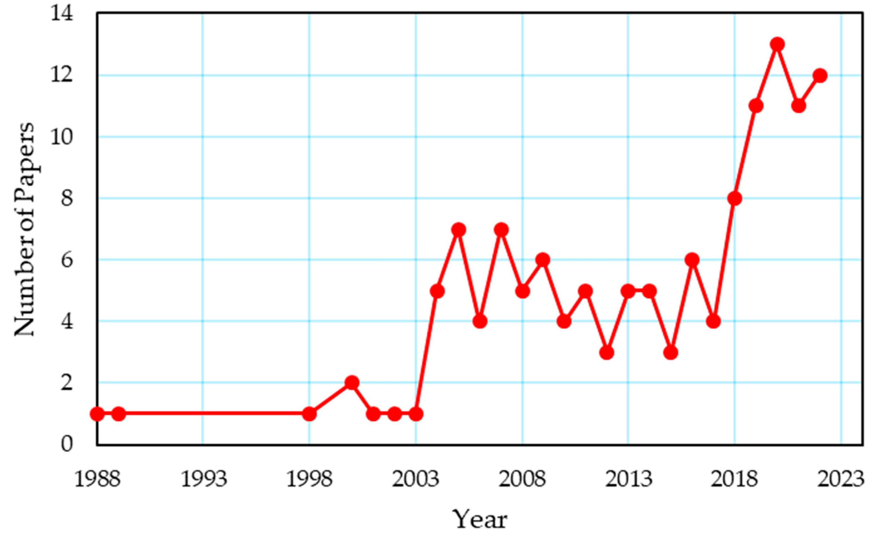
2. Review Methodology

Within the extent of this paper, studies on the experimental and theoretical research on the thermal coupling of metal hydrides with a fuel cell and/or an electrolyzer have been examined. Search engines, including Google Scholar, Web of Science, and Scopus, were employed to identify the studies that were within the scope of this review. The studies were constrained by the keywords “Metal Hydride Hydrogen Storage”, “Fuel Cell”, “Electrolyzer”, “Thermal Coupling”, “Thermal Management”, “Passive Thermal Management”, and “Active Thermal Management”. In Figure 1, the yearly distribution of papers on the thermal management of a metal hydride hydrogen tank coupled with a fuel cell and/or an electrolyzer using the aforementioned database is provided. This study looked at studies that used various thermal management techniques to enhance heat transfer in the MH tank. The scope of this review does not include MH tank studies that do not use a thermal management strategy. Studies with thermal coupling between MH tank and fuel cell or electrolyzer in integrated systems were considered, whereas studies without thermal coupling were disregarded. Section 3 summarizes the equations for the heat transfer of the MH tank during charging and discharging. In Section 4, a general overview of thermal management methods in MH tanks is presented. In Section 5, studies on the thermal coupling between a fuel cell and an MH tank are discussed. The studies examining the thermal coupling of the MH tank with the electrolyzer and the thermal coupling of both the electrolyzer and the fuel cell are given in Section 6 and Section 7, respectively.

3. Heat Transfer during Charging and Discharging Processes

According to their operating range, metal hydrides are classified as low-temperature hydrides (20–45 °C) [39,40] and high-temperature hydrides (165–200 °C) [39,41]. LaNi5 is the most widely used hydride metal among the low-temperature hydrides, with a maximum hydrogen storage capacity of 2% of its own weight. With the addition of Mg to LaNi5, this rate can increase to 5.7% [42]. Hydrogen can be stored in greater quantities by high-temperature hydrides than by low-temperature hydrides. For instance, MgH2 is the mostly preferred high-temperature hydride thanks to storing hydrogen up to 7.6% of its weight in it [42]. Keeping a metal hydride tank at a certain temperature range during absorption and desorption processes is vital for safe operation [43]. For example, for some commercial metal-hydride tanks based on AB5-type material (e.g., LaNi5 and MmNi5), the manufacturer recommends that the tank’s temperature should not go above 65 °C. If this temperature is surpassed, the internal pressure may cause damage to the tank walls [44]. For high-temperature hydrides, this temperature value may be higher. The hydriding and dehydriding reaction occurring in an MH tank can be shown as follows [45],
M + x 2 H 2   M H x + Q
where M is the metal (or metal alloy), x is the stoichiometric coefficient, M H x is the metal hydride compound, and Q is the heat of the reaction. Hydriding (absorption) is exothermic, whereas dehydriding (desorption) is endothermic.

3.1. Reaction Kinetics of Metal Hydride

In the absorption/desorption process, the amount of hydrogen converted into/released from the metal hydride per unit time is determined by the reaction kinetics [46]. The governing equations of reaction kinetics for absorption reaction can be written using Equation (2).
m ˙ a = C a exp ( E a R g a s T ) ln ( P P e q , a ) ( ρ s a t ρ s )
where m ˙ a the amount of hydrogen taken up by the hydride per unit time (kg/m3∙s), C a is the time constant (s−1), E a is the activation energy for the absorption process (J/mol), R g a s is the ideal gas constant (J/mol∙K), T is the temperature of the metal hydride bed (K), P is the operating pressure (bar), P e q , a is the equilibrium pressure for the absorption process (bar), which can be defined in Equation (4), ρ s a t is the density of the metal hydride at the maximum weight fraction (kg/m3), and ρ s is the metal hydride density (kg/m3). The mass flow rate of hydrogen released by the hydride, m ˙ d (kg/s), can be found using Equation (3).
m ˙ d = C d exp ( E d R T ) ln ( P P e q , d P e q , d ) ( ρ s ρ s , o )
where C d is the time constant (s−1), E d is the activation energy for the desorption process (J/mol), P e q , d is the equilibrium pressure for the desorption process (bar) which can be defined in Equation (4), ρ s , o is the density of the metal hydride (without hydrogen) (kg/m3).

3.2. Thermodynamics of Metal Hydride

The operation condition of absorption and desorption processes depends on the equilibrium pressure. The thermodynamic properties of the metal hydride are needed to determine this pressure. Although there are many methods in the literature to determine this pressure, the most widely used method is the Van’t Hoff equation, as shown in Equation (4) [47].
ln ( P e q P o ) = 1 R ( Δ H T Δ S )
where, P o is the reference pressure (usually set as 0.1–1 Mpa), Δ H and Δ S are the reaction enthalpy (J/mol∙H2) and the reaction entropy (J/molH2∙K) during the hydriding and dehydriding processes, respectively. The reaction enthalpy and entropy values vary depending on the type of hydride material. Table 1 shows the thermodynamic properties of different hydride-forming alloys for the absorption process.
In addition to the Van’t Hoff equation, the equilibrium pressure can be calculated as a function of the weight fraction as given in Equation (5). With this equation, the changes in the equilibrium with the weight fraction are taken into account with empirical coefficients [34].
ln P e q = Δ H R g T Δ S R g + ( ± φ 0 ) t a n [ π ( ( H M ) ( H M 0 ) ) 1 2 ] ± β 2
where, , φ 0 , and β are the PCT slope factor, the PCT slope constants, and the hysteresis factor, respectively. More information on the significance of these parameters can be found in [34].

3.3. Mass and Energy Balance Equations

The continuity equations for the solid and porous parts of the metal hydride bed [53] are shown in Equations (6) and (7).
( 1 ε ) ρ s t = m ˙
ε ρ g t + . ( ρ g V ) = m ˙
where ε is the porosity of the metal hydride bed, V is the velocity of hydrogen gas (m/s). The energy conservation equation of a metal hydride bed is described as [41],
( ρ C p ) e T t + ρ C p g ( V . T ) = ( k e T ) + Q s
The first term on the left-hand side refers to how the reactor’s internal energy changes over time. The second term on this side shows the advection term of the energy balance equation. If the velocity of hydrogen in the tank is considered zero, the second term can be neglected. The first term on the right side denotes heat conduction, while Q s denotes the heat generated or absorbed by the reaction. Effective volumetric heat capacity and effective thermal conductivity are given in Equations (9) and (10).
( ρ C p ) e = ε ( ρ C p ) g + ( 1 ε ) ( ρ C p ) m
k e = ε k g + ( 1 ε ) k m
where ( ρ C p ) g is the heat capacity of hydrogen gas, ( ρ C p ) m is the heat capacity of metal hydride material, k g is the thermal conductivity of hydrogen gas and k m is the thermal conductivity of metal hydride material. ( ρ C p ) e and k e change as the value of porosity changes over time during the hydriding and dehydriding [54]. Porosity can be defined as the ratio of porous volume to total volume in the metal hydride bed. Equation (11) represents that the porosity changes with time during the reaction due to the variation of the H/M ratio.
ε = 1 ( 1 ε 0 ) [ 1 + ( β v o l u m e 1 ) H M ]
where, ε 0 is the initial porosity of the metal hydride bed, β v o l u m e is the volume expansion ratio and H M is the hydrogen-to-metal ratio.
In the energy balance, Equation (8) and the continuity Equations (6) and (7), the velocity of hydrogen can be found using Darcy’s law using Equation (12).
V = K μ g P g
where μ g is the viscosity of the hydrogen gas (kg/m∙s), K is the permeability of metal hydride (m2), and P g is the pressure gradient of the metal hydride tank (Pa) (including buffer area and porous media). Since the chemical reaction of the metal hydride is reversible, the heat required by the metal hydride or released to the environment is defined by Omrani et al. [26] as follows,
Q ˙ M H = m ˙ H 2 · | Δ H M H |
where m ˙ H 2 is the charge or discharge mass flow rate (kg/s), Δ H M H is the enthalpy change in reaction (J/kg) and Q ˙ M H is the heat demand or released heat by a hydride bed.

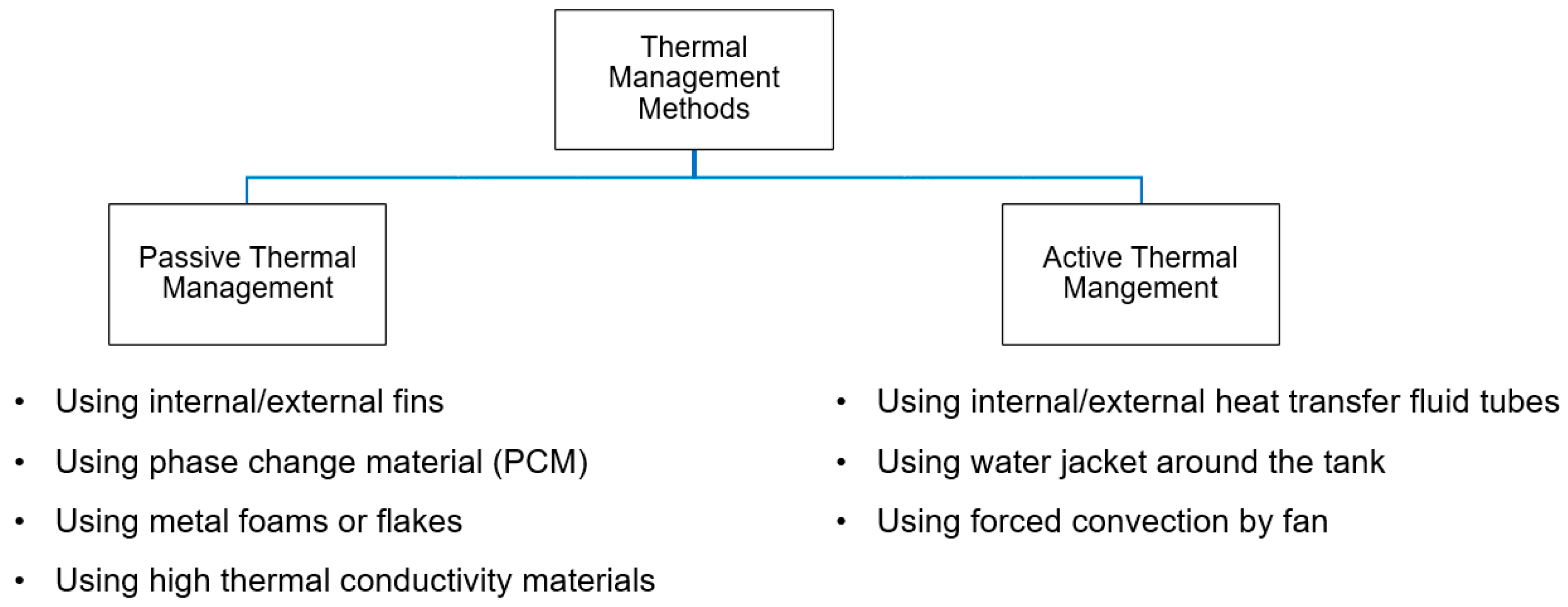
4. Methods for Thermal Management of MHs

In this section, the thermal management methods of MH tanks are explained to adjust the temperature changes in the tank occurring as a result of the heat generated or absorbed during charging and discharging. Basically, thermal management methods can be classified into two main groups: active and passive. In Figure 2, the main thermal management methods for the MH tanks are given.

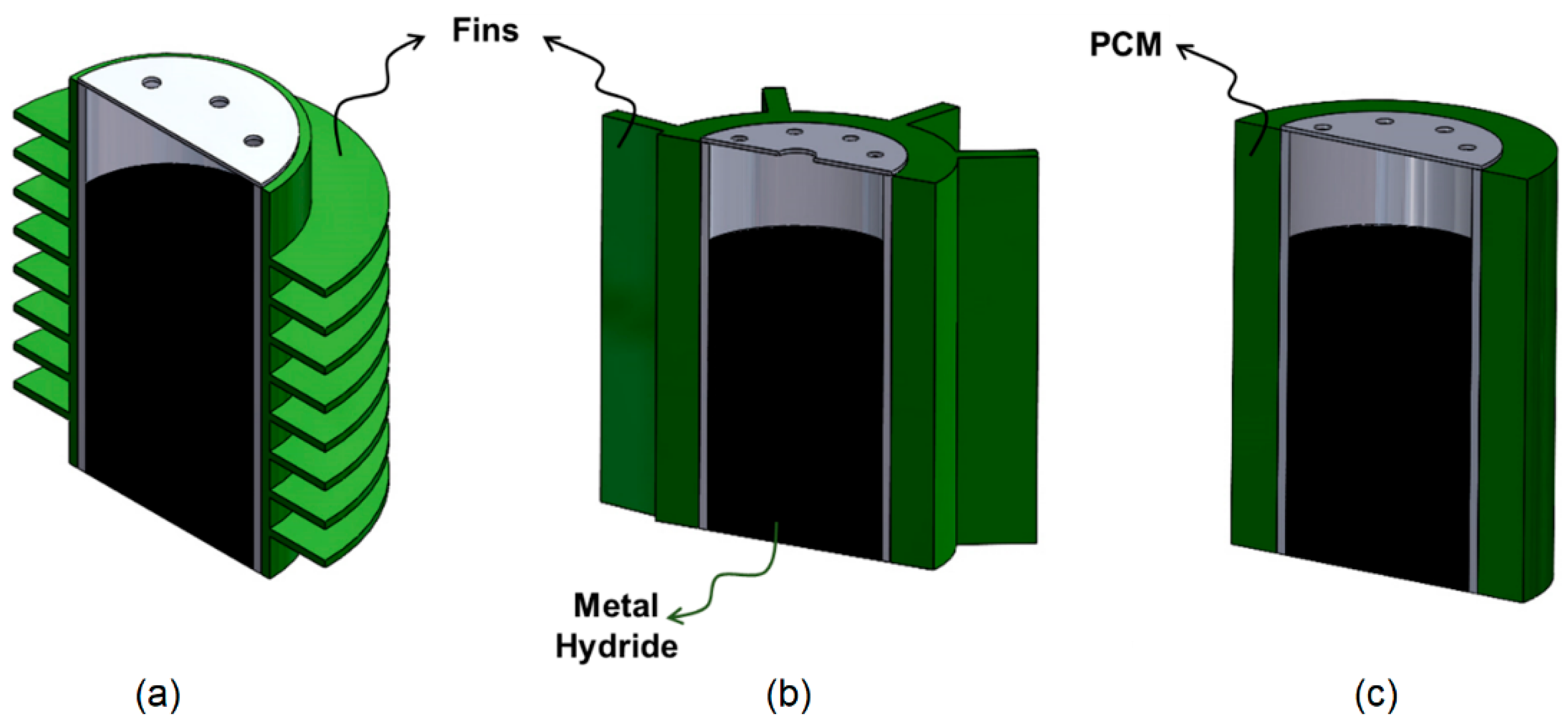
4.1. Passive Thermal Management

In passive thermal management, the main heat transfer mechanism used to adjust the tank’s temperature is natural convection. Where natural convection is insufficient to increase heat transfer, different types of designs can be selected for MH tanks. Fins can be added to the inner or outer surface of the MH tank by using materials with high conductivity since expanding the heat transfer area will increase heat transfer. Fins can be integrated inside or outside the MH tank in different ways, such as horizontal [55,56], longitudinal [57,58], tree-shaped [46], honeycomb [59,60], or leaf-vein [61]. Nyamsi et al. [62] optimized the analytical solution results they generated from a single fin by varying the fin thickness and radius in order to investigate the impact of fin structure on hydrogen storage. They then developed a numerical model to validate the analytical study. As a result, they found that a 13% reduction in thermal resistance reduced charging time by 42%. To increase the surface area even further, structures such as flakes can be added to the fins. Singh et al. [63] experimented with the internal finned MH tank with and without cooper flakes to investigate the absorption effect of cooper flakes. As a result, they found that the copper flakes reduced the charging time by 11% for the absorption capacity of 1.2 wt%.
PCMs store the heat released as a result of the reactions taking place in the MH tank during absorption and prevent the tank from overheating. During the desorption process, it provides the heat needed by the tank to the tank. Due to these properties, PCM can be used as a passive thermal management method in MH tanks [64,65,66]. Alqahtani et al. [67] proposed a new MH-PCM sandwich design combining the MH tank with cascaded PCM beds and investigated the heat transfer during charging and discharging using PCM with two different melting temperatures. As a result, they found that their proposed MH-PCM sandwich design reduces charge and discharge by 26% and 51%, respectively. El Mghari et al. [68] numerically investigated the absorption and desorption processes in an MH tank equipped with PCM. According to parametric studies, there is a significant influence of PCM thermal conductivity and latent heat on the rate of absorption and desorption. Metal foams are also used to increase the thermal conductivity of MH tanks [55,69]. The impact of adding aluminum foam to metal hydride on mass and heat transport was examined numerically by Minko et al. [19]. As a result, they observed that the aluminum foam accelerated mass and heat transfer. Compared to the condition without aluminum foam, they discovered that using foam reduced the sorption time in half, but the volumetric capacity was decreased by 9%. To increase the thermal conductivity, high thermal conductivity materials such as graphite or carbon can be mixed into metal powder [70]. Ref. [38] contains more detailed information on this subject. Zhu et al. [18] used expanded natural graphite (ENG) to increase heat transfer in the MH. As ENG decreases hydrogen density in compacted composites, they improved the ENG content to promote heat transfer for multilayer MH bed configurations. They also suggested an optimization approach based on the entransy dissipation extremum principle (EDEP) to optimize the ENG distribution in the MH bed. They consequently observed that absorption enhanced with ENG usage. The optimized design based on EDEP had a quicker reaction time, more consistent bed temperature dispersion, and a 15.33% greater gravimetric exergy–output ratio than a configuration with uniform ENG content. Passive thermal management methods using horizontal fins, longitudinal fins and PCM are given in Figure 3.

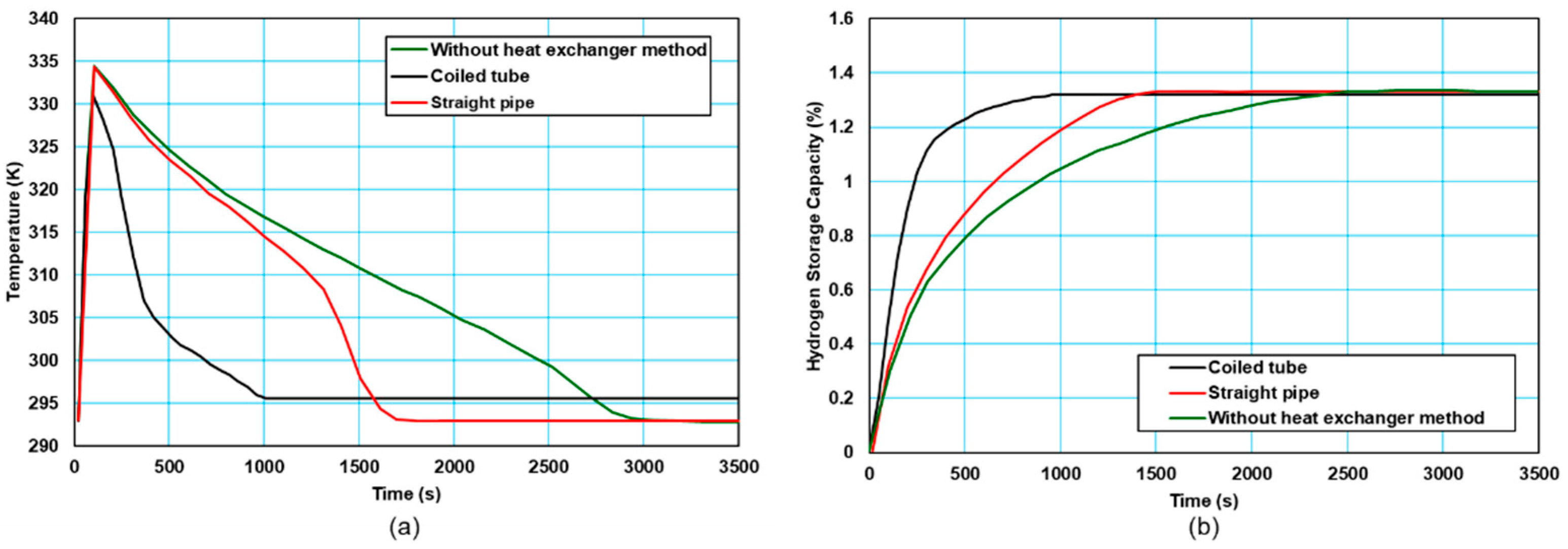
4.2. Active Thermal Management

In contrast to passive thermal management, active thermal management comprises thermal management methods based on forced convection. In active thermal management, heat exchanger systems can be integrated into the MH tank as internal or external. Cooling fluids such as air or water can be used to remove the heat released during the absorption process from the tank and to provide the tank with the heat required by the tank during desorption. There are several studies on active thermal management in the literature [23]. Active thermal management can be achieved with a water jacket or coiled tubes integrated outside the MH tank or with straight or coiled tubes running through the tank. Karmakar et al. [71] integrated a cooling tube inside the MH reactor and a water jacket on the outside. They experimentally investigated the amount of hydrogen stored for the following cases: (i) the system was only in natural convection, (ii) only the cooling tubes were active, and (iii) the cooling tubes and external water jacket were active together. As a result, they observed that the combination of the cooling tubes and an external water jacket increased the absorption and desorption performance. Tong et al. [21] investigated the thermal interaction in the MH tank by using different combinations of coiled tubes and straight pipes in their study. As a result, they found that the dual coiled-tube integrated heat exchanger was effective in increasing the hydrogen storage efficiency of the MH tank. As shown in Figure 4, during absorption, it is seen that the tank temperature decreases more quickly and the hydrogen storage time is reduced when an active thermal management method is used. There are several studies in the literature that use air as a heat transfer fluid in place of water. Busque et al. [22] compared natural and forced convection by using a fan in the experimental system they set up to investigate the absorption process of the MH tank and the effects of parameters. As a result, the parameters that most affect the absorption are the absorption rate constant, activation energy, and thermal conductivity, and while the increase in porosity decreases the absorption rate and the amount of stored hydrogen, a higher cooling level is required for a faster absorption process. Active thermal management methods using straight pipe, using forced convection, and using a water jacket are given in Figure 5.
There are several studies in the literature on the thermal management of the MH tank that combine active and passive methods [65,72]. Askri et al. [20] analyzed the storage time of hydrogen by mathematically analyzing the MH tank model in different configurations (a cylindrical tank, a cylindrical tank with external fins, a cylindrical tank with a concentric tube filled with flowing cooling fluid, and a cylindrical tank with a concentric tube equipped with fins). As a result, it was observed that the storage time was approximately 80% better in the configuration using a cylindrical tank with a concentric tube equipped with fins. Using active and passive management, Mellouli et al. [73] evaluated temperature variations mathematically when the absorption process in the MH tank over three distinct configurations that used only PCM (Case 1), PCM with straight tube (Case 2), and PCM with U-type tubes (Case 3). The results showed that the straight tube used in Case 2 removed 70% of the heat released during absorption from the system and reduced the storage time by 94% compared to Case 1. In Case 3, all the heat of the reaction was stored in the PCM, thus reducing the storage time by 72%. Afzal et al. [74] designed a shell and tube-type reactor containing 7 MH tanks. They added four longitudinal fins in each MH tank. They investigated absorption and desorption processes under different operating parameters. When the supply pressure was increased to 35 bar, the MH tank’s performance was observed to be promising for the absorption process. They stated that when the temperature of the heat transfer fluid was increased from 298 K to 308 K, the desorption rate increased. Darzi et al. [75] investigated the temperature changes in the MH tank during the absorption process using a water jacket and fins. Using different temperatures, pressure, porosity, Reynolds number, and fin number, the effects of these parameters on the hydrogen filling amount were investigated. They concluded that the change in supply pressure and the temperature had no effect on the absorption rate in the absence of a thermal management method and that the rate of absorption increased significantly in the case of adding a fin and water jacket. In Table 2, the advantages and disadvantages of the thermal management of MHs are given.

5. Thermal Coupling of MH Tanks and PEM Fuel Cell during the Discharge Process

Proton exchange membrane fuel cells (PEMFC) are electrochemical energy conversion systems that produce electrical energy directly by utilizing the chemical energy of hydrogen with high electrical efficiency. In fuel cells, heat is generated due to unavoidable entropy changes in the reaction and irreversibilities due to polarizations. The heat generated can be found with the following equations considering the higher heating value (assumed that water is produced in liquid form), Equation (14), and lower heating value (assumed that water is produced in vapor form), Equation (15), of the hydrogen [37].
Q ˙ F C = N c e l l · i c e l l · A c e l l ( 1.48 V c e l l )
Q ˙ F C = N c e l l · i c e l l · A c e l l ( 1.25 V c e l l )
where N c e l l is the number of cells, i c e l l is the current density (A/cm2), A c e l l is the effective membrane area (cm2), and V c e l l is the output voltage of the fuel cell (V). The waste heat must be removed from the fuel cell system to maintain the performance of the fuel cell and to prevent any damage to the membrane. For this, different cooling systems such as edge cooling, air cooling, liquid cooling, or phase change cooling can be used. For small-size fuel cells (i.e., <2 kW), simple cooling methods such as air cooling or heat pipes can be utilized. For PEMFCs with 5 kW and more power output, liquid cooling methods are more suitable [37]. The waste heat obtained from the fuel cell is approximately 30–40% of the heat produced by the fuel cell [38]. An example of energy flow in a fuel cell is given in the Sankey diagram in Figure 6 [76,77].
The waste heat generated by the fuel cell can be transferred to MH tanks through the convection mechanism to increase the hydrogen desorption rate. Thus, while the MH tank provides hydrogen to the fuel cell for electricity generation, the heat it needs can be met by directing the heat produced as a result of the operation of the fuel cell to the tank. The waste heat of the fuel cell can be transmitted directly to the MH tank using a fan or air blower (Figure 7a). McDonald and Rowe [25] investigated three possible configurations (with no heat transfer method, external fins around the MH tank, and annular MH tank design) while mathematically combining the FC to remove the waste heat. As a result, they concluded that MH tanks can deliver the hydrogen flow necessary for the fuel cell in designs where they utilize a fin and annular tube but that it is insufficient in configurations where they do not use a thermal management method. Davids et al. [78] thermally coupled a 130 W PEMFC and a 90 NL MH tank through experimental studies. To use the hydrogen in the tank at the maximum level, they integrated MH powder into a thermally expanded graphite, added a fin to the outside of the MH tank to increase the heat transfer area, and transferred the waste heat of the fuel cell to the MH tank with the help of a fan. As a result, when the fuel cell operated under 60, 100, and 120 W loads, it worked for 75, 41, and 35 min, respectively, and on average more than 87% of the stored hydrogen was used at each load. Omrani et al. [26] investigated thermally coupled 2.5 kW open cathode PEMFC and nine 800 NL MH tanks experimentally. By transmitting the waste heat of the PEMFC to the MH tanks, they checked whether the MH tanks could provide the required hydrogen flow under different loads (500, 1000, 1500, and 2000 W). As a result, they obtained that when there is no thermal coupling between the fuel cell and the MH tank, the tanks are sufficient under a 500 kW load, and thermal coupling is required for higher loads. There are other studies that directly use the fuel cell’s waste heat to perform thermal coupling between the MH tank and the fuel cell in the literature [79,80].
In terms of their straightforward design and lightweight cooling components, air cooling systems are advantageous to liquid cooling systems. The disadvantage of air-cooling systems is that they can remove less heat than liquid cooling systems because of the air’s lower heat capacity. A heat exchanger utilizing the heat transfer fluid can also be included in the system to complete the thermal coupling between the fuel cell and the MH tank. The waste heat of the fuel cell is sent to a heat transfer fluid, which can be directed to the MH tank and used to increase the hydrogen flow rate during desorption. In Figure 7b,c, active thermal management methods between the PEM fuel cell and MH tank that use heat transfer fluid are given. Urbanczyk et al. [81] thermally coupled a high-temperature PEM fuel cell and a sodium-alanate-based Mh tank by using heat transfer fluid. Evaluating the maximum hydrogen storage capacity in their studies, they produced three different tanks, analyzed them experimentally, and determined the best design. Chabane et al. [43] proposed a thermally coupled PEM fuel cell and MH tank using heat transfer fluid for use in vehicles. As a result, they stated that reaching the temperature required for the hydrogen desorption of the MH tank negatively affects the temperature of the fuel cell, and the fuel cell cannot reach the operating temperature. Forde et al. [82] experimentally investigated the performance of a thermally coupled MH with a 1.2 kW PEMFC. As a result, they stated that the hydrogen flow required to obtain the desired flow from the fuel cell can be obtained by transmitting 25% of the cooling load of the fuel cell to the MH tank. Zhu et al. [27] mathematically investigated the thermal coupling system between the fuel cell and the MH tank for use in transportation applications. By thermally connecting the fuel cell and MH tanks, they transferred the waste heat from the fuel cell to the heat transfer fluid and then conveyed the heat transfer fluid to the MH tanks. They stated that the fuel cell system they developed had greater than 3% efficiency and greater than 10% fuel savings.
Apart from the active coupling of the fuel cell and the MH tank, some studies use passive thermal management methods to transmit the waste heat of the fuel cell to the MH tank. Tetuko et al. [28] mathematically combined 500 W PEMFC with MH tanks using heat pipes (Figure 8a). The hydrogen flow rate required for the fuel cell to operate at maximum power is 7.2 slpm, and the hydrogen flow rate provided by MH tanks at 25 °C ambient temperature is 2.5 slpm. They concluded that the MH tanks needed little less than 20% of the total cooling load of the stack at the highest power point in order to achieve the necessary 7.2 slpm hydrogen flow rate from the tanks at 35 °C. Tetuko et al. [29] thermally coupled a 130 W fuel cell and an 800 NL MH tank using a heat pipe experimentally and mathematically (Figure 8b). As a result, they stated that 30% of the cooling load of the fuel cell is sufficient for the MH tank to provide the 1.7 slpm hydrogen flow required for the fuel cell to operate at 130 W.
Except for PEMFC, another type of fuel cell, SOFC, can be thermally coupled with an MH tank [83,84]. Based on the thermodynamic principles, Yiotis et al. [85] examined the thermal coupling potential between a high-temperature metal hydride tank and a SOFC. According to the results of their models, thermal coupling was found to be feasible for MHs with extremely high desorption enthalpies, which effectively results in high fuel consumption rates in SOFC. A system consisting of a SOFC and a magnesium-based MH tank was studied by conducting a thermal analysis in the study of Shao [86]. They performed thermal coupling between the SOFC and MH tank by transferring waste heat from the SOFC to the tank. As a result of thermal coupling, the system’s electrical efficiency was 68.6%, and its thermal improvement was 13.4%. In Table 3, the thermal management methods applied when the MH tank is employed in the fuel cell or electrolyzer systems are listed.

6. Thermal Management of MH Tanks in Integrated Fuel Cell and Electrolyzer Systems

In water electrolyzers, water is electrochemically split into oxygen and hydrogen. When electricity is generated by renewable energy resources, clean H2 is created using these electrolyzers. The generated hydrogen can then be used for different purposes, such as generating heat and electricity [30]. The intermittent nature of renewable energy resources such as solar and wind can be balanced with the use of electrolyzers. Here, excess power generated can be utilized in a water electrolyzer to generate green hydrogen, and this hydrogen can be stored for further use [31,32]. There are three operational modes for electrolyzers depending on the energy balance at the electrolyzer level: exothermic, isothermal, and endothermic. The steam temperature reduces from the electrolyzer’s input to its output when it is operating in the endothermic mode. Although this mode causes high production costs, it yields the greatest electrolyzer efficiency [82]. The steam temperatures at the input and exit are the same in the isothermal mode. The exothermic mode’s performance is lower compared to this mode.
With the thermal management in electrolyzers, the working temperature must be kept within the appropriate limits to ensure the safe and efficient operation of the electrolyzer and to protect electrolytes and membranes from corrosion and other life-shortening problems [91]. Internal thermal management of electrolyzers typically uses two strategies [32]. The electrolyzer’s temperature can be managed using either an excess of process cooling fluid or water that circulates in a different circuit. When cooling is the only goal, combining the two approaches is also possible and advantageous for spreading the workload. However, employing only one approach rather than combining the two is preferred since it is crucial to confine the heat in a closed circuit for the purpose of reusing it in a different process [32]. The efficient heat transfer between the water and the cell is the main benefit of cooling with extra process water. To maintain constant moisture in the membrane and, more importantly, to increase reaction kinetics by guaranteeing a large contact surface, the electrodes and current collectors are porous. This results in a very efficient heat transfer, which is a desirable side effect. The risk of pollution is the biggest drawback. A system that relies on process water cooling would circulate demineralized water widely [32]. Since it does not directly affect the performance of the cell, a divided cooling system does not have the pollution issue and permits a wider range of design parameters. However, it requires additional piping for the coolant to be created somewhere in the stack. These channels could be seen within the bipolar plates that split the cells. However, there is not much room for these channels because manufacturers are working hard to make electrolyzers as small as possible. Fortunately, this method of cooling is quite common in the fuel cell industry [92,93,94,95], and producing these plates is quite a widespread process.
Raju and Khaitan [87] examined a hybrid hydrogen storage system that includes an electrolyzer to produce hydrogen for use in residential applications and a PEMFC to generate electricity from H2. The authors supposed that there is a heat sink that can efficiently remove this heat produced while the electrolyzer works to maintain its operating temperature at 80 °C. At the same time, they analyzed in detail the dynamics of charging and thermal management matters of the metal hydride storage system. The storage of H2 produced from excess wind energy collected from the hybrid wind settlement system was suggested, and LaNi5-based MH was selected as the storage medium. To ensure the effective absorption and desorption of H2 from the storage bed, a suitable heat exchanger was included in the bed. There were 24 cooling tubes in the bed. The cooling and metal hydride pipes that ran the length of the bed were related to aluminum fins. They achieved a decent heat transfer between the metal hydride and the coolant with this shape. The coolant moved through the pipes, cooling the bed to the proper temperature. The coolant flow rate and the temperature have an important effect on how well the bearing works [96,97].
Numerous research studies have been conducted on MH-based H2 storage systems in microgrids; the majority of them are centered on controlling storage systems, power generators, and working loads [98,99,100]. For effective hydrogen use in microgrids, energy management procedures and optimization methods are also utilized. At the same time, for the steady functioning of the hydrogen production and usage units in the hydrogen energy-based microgrid, some emphasis is given to the scheming and proper process of the MH thermal management system. Operating time affects and strongly interdepends on MH operational factors such as fluctuations in temperature, charging/discharging value, pressure, the quantity of heat production/absorption, and appropriate heating/cooling management. Because the hydrogen loading and unloading processes are exothermal and endothermal, the cooling and heating systems play a significant role in the dynamic efficiency parameter of the MH. Since the working power of the electrolyzer and PEMFC in the H2-based microgrid determines the rates of hydrogen charging and discharging, respectively, heating and cooling control should be properly designed and implemented to ensure the overall system operates as intended.
The impact of exterior heating and cooling systems on the dynamic operating charge and discharge of MH was examined by Kumar et al. [89]. The computer simulation model assisted in the design of the outer thermal management system for optimal system working by predicting the possibility of dynamic charge/discharge value with changes in external cooling/heating. In-depth experimental examination of units for producing and using hydrogen, exterior thermal management system, filling and discharging rates, and dynamic pressure and temperature variation was provided. The chiller and heater systems, respectively, met the heating and cooling necessities during the H2 loading and unloading procedures for the MH tank. A PID-based temperature controller was used to regulate the temperature of the heater and chiller systems. Han et al. [96] suggested an implementation-focused design and a new system integration technique to maximize energy concentration while combining their traditional technologies for the electrolyzer, MH and PEMFC. To increase energy density and usability, they separated the charge and discharge systems. A water electrolyzer and an MH cooling system were combined to form the charging component. An MH, a PEMFC stack, and a power conditioning system were all included in the purging component as a single unit. They used an air-cooling fan to drastically cut the charging time because the hydrogen-filling process in the MH is an exothermal reaction. Ghayur and Verheyen [101] investigated the waste heat integration potential in an energy storage facility consisting of a SOFC, an alkaline electrolyzer, and a magnesium hydride tank. They converted excess grid power to hydrogen and stored it as magnesium hydride. Waste heat produced during the storage process was used to offset the electrolyzer’s need for hot water. The simulation results showed a 20% decrease in heat energy depletion by utilizing waste heat. The SOFC uses stored hydrogen to deliver power when it is needed. The magnesium hydride tank’s heat need for desorption was satisfied by the waste heat from SOFC. According to computer simulation results, the SOFC’s waste heat was just enough to pre-heat the oxygen and hydrogen, as well as desorbing the hydrogen from the magnesium hydride tank. Gonzatti et al. [88] examined an alkaline electrolyzer, a hydrogen storage device made of a metal hydride, and an experimental power system that uses PEM fuel cells to store and produce electrical and thermal energy. Since the heat released in the adsorption process decreases the adsorption rate with rising temperature, they circulated water at ambient temperature in the inner pipes of the tank to remove this heat. Moreover, since the desorption of H2 is an endothermal reaction that removes heat from the ambient, they heated the MHs, thus releasing the stored H2 by circulating heated water through the inner tubes of the tank.

7. Conclusions

This study examined modeling methods for heat transfer during charging and discharging of the MH tank, passive and active thermal management, and thermal coupling methods with fuel cell and electrolyzer systems in detail and presented as a review study. Chemical reactions between hydrogen, metal and metal hydride cause the charge and discharge of hydrogen in MH tanks. The hydrogen storage capacity of the tank and the hydrogen charge/discharge flow is adversely impacted by temperature variations during the absorption and desorption processes, which occur as exothermic and endothermic, respectively. In order to enhance heat transfer, thermal management methods are used actively and passively within or outside the tank. The most commonly utilized structures are fin structures and straight pipes. The amount of hydrogen storage and the time it takes for hydrogen to absorb and desorb are significantly impacted by the passive and active thermal management strategies, according to research in the literature. It is clear that the duration and the amount of hydrogen that can be stored may be increased by almost a factor of two with the right thermal management techniques.
In fuel cell and MH tank systems, the MH tank should supply enough hydrogen flow rate to the fuel cell to operate at the desired power. The hydrogen flow rate is decreased due to the drop in tank temperature brought on by the chemical processes involved in the discharge from the MH tank. The waste heat generated during fuel cell operation is directed to the MH tank, and the tank temperature is managed in order to produce hydrogen at the desired flow rate. The thermal coupling of a fuel cell and an MH tank is often carried out through active management. Low-power fuel cells (e.g., <2.5 kW) with air cooling have been mainly chosen in the studies conducted in this area. To transport waste heat to the MH tank, active methods such as heat exchanger systems with the flow of a heat transfer fluid or forced convection with the aid of fans are preferred. This review has shown that there is a need to carry out more studies on the thermal management of MH tank systems with fuel cells having higher power outputs (i.e., >2.5 kW). This review has also shown that even though PEMFC is the most common type of fuel cell used, limited investigations employing SOFC are also documented in the literature. Using SOFC instead of PEMFC is especially preferred for cases where high-temperature MH materials such as MgH2 are used.
In addition, the thermal management between the hydrogen production unit (electrolyzer), usage unit (fuel cell), and hydrogen storage unit (metal hydride) is investigated. When the studies in the literature are examined, two different strategies are used in the internal thermal management of electrolyzers; the temperature of the electrolyzer is managed by using an excess of process coolant or water circulating in a different circuit. However, since the operating power of the electrolyzer and PEMFC in the H2-based microgrid determines the hydrogen charging and discharging rates, respectively, thermal management (heating and cooling control) must be properly designed and implemented to ensure the overall system functions as intended.
The interest in this topic has been shown by the growing number of studies on the thermal coupling of MH tanks with a fuel cell and/or an electrolyzer, especially within the last 5 years. This study aimed to provide guidelines for future research on MH hydride thermal management and its thermal combination with fuel cells or electrolyzers. It is clear that for MH tanks to have quicker charge/discharge times and greater hydrogen storage capacity, a thermal management method is required. Among the different methods, active types are superior due to their ability to adjust the tank temperature. However, to use metal hydride hydrogen tanks together with an active thermal management system in applications (e.g., fuel cell powered forklift and golf cart), future studies should focus on reducing the weight and volume of this system. More effective techniques and designs should be proposed to direct the waste heat from the fuel cell to the metal hydride tank. In addition, the dynamic performances of the systems, including an electrolyzer, metal hydride tanks, and a fuel cell, increase with the use of an appropriate thermal management strategy. Hence, the necessity of using thermal management in these systems is emerging to increase the overall efficiency of microgrids. In such systems, the operation mode of the electrolyzer should also be selected in a way to optimize the heat balance of the overall system.

Author Contributions

Conceptualization, O.K. and C.O.C.; methodology, C.O.C.; investigation, S.A.C., T.D., G.S., O.K., and C.O.C.; writing—original draft preparation, S.A.C., T.D., and G.S.; writing—review and editing, O.K. and C.O.C.; supervision, O.K. and C.O.C.; project administration, C.O.C.; funding acquisition, C.O.C. All authors have read and agreed to the published version of the manuscript.

Funding

This research was funded by The Scientific and Technological Research Council of Turkey (TUBITAK), grant number 220N405.

Data Availability Statement

No new data were created or analyzed in this study.

Conflicts of Interest

The authors declare no conflict of interest. The funders had no role in the design of the study; in the collection, analyses, or interpretation of data; in the writing of the manuscript; or in the decision to publish the results.

References

  1. The Paris Agreement n.d. Available online: https://unfccc.int/process-and-meetings/the-paris-agreement/the-paris-agreement (accessed on 24 October 2022).
  2. Woodfield, P.L.; Monde, M.; Takano, T. Heat Transfer Characteristics for Practical Hydrogen Pressure Vessels Being Filled at High Pressure. J. Therm. Sci. Technol. 2008, 3, 241–253. [Google Scholar] [CrossRef] [Green Version]
  3. Aceves, S.M.; Espinosa-Loza, F.; Ledesma-Orozco, E.; Ross, T.O.; Weisberg, A.H.; Brunner, T.C.; Kircher, O. High-density automotive hydrogen storage with cryogenic capable pressure vessels. Int. J. Hydrogen Energy 2010, 35, 1219–1226. [Google Scholar] [CrossRef]
  4. Ahluwalia, R.K.; Peng, J.K. Dynamics of cryogenic hydrogen storage in insulated pressure vessels for automotive applications. Int. J. Hydrogen Energy 2008, 33, 4622–4633. [Google Scholar] [CrossRef]
  5. Ahluwalia, R. Sodium alanate hydrogen storage system for automotive fuel cells. Int. J. Hydrogen Energy 2007, 32, 1251–1261. [Google Scholar] [CrossRef]
  6. Raju, M.; Kumar, S. System simulation modeling and heat transfer in sodium alanate based hydrogen storage systems. Int. J. Hydrogen Energy 2011, 36, 1578–1591. [Google Scholar] [CrossRef]
  7. Lozano, G.A.; Eigen, N.; Keller, C.; Dornheim, M.; Bormann, R. Effects of heat transfer on the sorption kinetics of complex hydride reacting systems. Int. J. Hydrogen Energy 2009, 34, 1896–1903. [Google Scholar] [CrossRef]
  8. Raju, M.; Kumar, S. Optimization of heat exchanger designs in metal hydride based hydrogen storage systems. Int. J. Hydrogen Energy 2012, 37, 2767–2778. [Google Scholar] [CrossRef]
  9. Ahluwalia, R.K.; Peng, J.K. Automotive hydrogen storage system using cryo-adsorption on activated carbon. Int. J. Hydrogen Energy 2009, 34, 5476–5487. [Google Scholar] [CrossRef]
  10. Kumar, S.; Raju, M.; Senthil Kumar, V. System simulation models for on-board hydrogen storage systems. Int. J. Hydrogen Energy 2012, 37, 2862–2873. [Google Scholar] [CrossRef]
  11. Bénard, P.; Chahine, R. Modeling of adsorption storage of hydrogen on activated carbons. Int. J. Non-Linear Mech. 2001, 36, 849–855. [Google Scholar] [CrossRef]
  12. Ley, M.; Meggouh, M.; Moury, R.; Peinecke, K.; Felderhoff, M. Development of Hydrogen Storage Tank Systems Based on Complex Metal Hydrides. Materials 2015, 8, 5891–5921. [Google Scholar] [CrossRef] [PubMed]
  13. Johnson, T.A.; Jorgensen, S.W.; Dedrick, D.E. Performance of a full-scale hydrogen-storage tank based on complex hydrides. Faraday Discuss 2011, 151, 327. [Google Scholar] [CrossRef] [PubMed]
  14. Galli, S.; De Francesco, M.; Monteleone, G.; Oronzio, R.; Pozio, A. Development of a compact hydrogen generator from sodium borohydride. Int. J. Hydrogen Energy 2010, 35, 7344–7349. [Google Scholar] [CrossRef]
  15. Valenti, G. Hydrogen liquefaction and liquid hydrogen storage. In Compendium of Hydrogen Energy; Elsevier: Cambridge, UK, 2016; pp. 27–51. [Google Scholar] [CrossRef]
  16. Abe, J.O.; Popoola, A.P.I.; Ajenifuja, E.; Popoola, O.M. Hydrogen energy, economy and storage: Review and recommendation. Int. J. Hydrogen Energy 2019, 44, 15072–15086. [Google Scholar] [CrossRef]
  17. Da Rosa, A.V.; Ordóñez, J.C. Fundamentals of Renewable Energy Processes, 4th ed.; Birtcher, K., Ed.; Academic Press: Cambridge, MA, USA, 2021; pp. 478–494. [Google Scholar]
  18. Zhu, Z.; Bao, Z.; Wu, D. Optimization of the content distribution of expanded natural graphite in a multilayer metal hydride bed for thermochemical heat storage. Appl. Therm. Eng. 2022, 216, 119115. [Google Scholar] [CrossRef]
  19. Minko, K.B.; Artemov, V.I.; Yan’kov, G.G. Numerical study of hydrogen purification using metal hydride reactor with aluminium foam. Appl. Therm. Eng. 2015, 76, 175–184. [Google Scholar] [CrossRef]
  20. ASskri, F.; Bensalah, M.; Jemni, A.; Bennasrallah, S. Optimization of hydrogen storage in metal-hydride tanks. Int. J. Hydrogen Energy 2009, 34, 897–905. [Google Scholar] [CrossRef]
  21. Tong, L.; Xiao, J.; Yang, T.; Bénard, P.; Chahine, R. Complete and reduced models for metal hydride reactor with coiled-tube heat exchanger. Int. J. Hydrogen Energy 2019, 44, 15907–15916. [Google Scholar] [CrossRef]
  22. Busqué, R.; Torres, R.; Grau, J.; Roda, V.; Husar, A. Effect of metal hydride properties in hydrogen absorption through 2D-axisymmetric modeling and experimental testing in storage canisters. Int. J. Hydrogen Energy 2017, 42, 19114–19125. [Google Scholar] [CrossRef]
  23. Urunkar, R.U.; Patil, S.D. Enhancement of heat and mass transfer characteristics of metal hydride reactor for hydrogen storage using various nanofluids. Int. J. Hydrogen Energy 2021, 46, 19486–19497. [Google Scholar] [CrossRef]
  24. Colpan, C.O.; Nalbant, Y.; Ercelik, M. 4.28 Fundamentals of Fuel Cell Technologies. Compr. Energy Syst. 2018, 4, 1107–1130. [Google Scholar] [CrossRef]
  25. MacDonald, B.D.; Rowe, A.M. A thermally coupled metal hydride hydrogen storage and fuel cell system. J. Power Sources 2006, 161, 346–355. [Google Scholar] [CrossRef]
  26. Omrani, R.; Nguyen, H.Q.; Shabani, B. Thermal coupling of an open-cathode proton exchange membrane fuel cell with metal hydride canisters: An experimental study. Int. J. Hydrogen Energy 2020, 45, 28940–28950. [Google Scholar] [CrossRef]
  27. Zhu, D.; Ait-Amirat, Y.; N’Diaye, A.; Djerdir, A. Active thermal management between proton exchange membrane fuel cell and metal hydride hydrogen storage tank considering long-term operation. Energy Convers. Manag. 2019, 202, 112187. [Google Scholar] [CrossRef]
  28. Tetuko, A.P.; Shabani, B.; Andrews, J. Thermal coupling of PEM fuel cell and metal hydride hydrogen storage using heat pipes. Int. J. Hydrogen Energy 2016, 41, 4264–4277. [Google Scholar] [CrossRef]
  29. Tetuko, A.P.; Shabani, B.; Omrani, R.; Paul, B.; Andrews, J. Study of a thermal bridging approach using heat pipes for simultaneous fuel cell cooling and metal hydride hydrogen discharge rate enhancement. J Power Sources 2018, 397, 177–188. [Google Scholar] [CrossRef]
  30. Eveloy, V.; Gebreegziabher, T. A Review of Projected Power-to-Gas Deployment Scenarios. Energies 2018, 11, 1824. [Google Scholar] [CrossRef] [Green Version]
  31. Kharel, S.; Shabani, B. Hydrogen as a Long-Term Large-Scale Energy Storage Solution to Support Renewables. Energies 2018, 11, 2825. [Google Scholar] [CrossRef] [Green Version]
  32. Tiktak, W.J. Heat Management of PEM Electrolysis; Delft University of Technology: CD Delft, The Netherlands, 2019. [Google Scholar]
  33. Srinivasa Murthy, S. Heat and Mass Transfer in Solid State Hydrogen Storage: A Review. J. Heat Transf. 2012, 134, 031020. [Google Scholar] [CrossRef]
  34. Mohammadshahi, S.S.; Gray, E.M.; Webb, C.J. A review of mathematical modelling of metal-hydride systems for hydrogen storage applications. Int. J. Hydrogen Energy 2016, 41, 3470–3484. [Google Scholar] [CrossRef]
  35. Shafiee, S.; McCay, M.H. Different reactor and heat exchanger configurations for metal hydride hydrogen storage systems–A review. Int. J. Hydrogen Energy 2016, 41, 9462–9470. [Google Scholar] [CrossRef]
  36. Lototskyy, M.V.; Tolj, I.; Pickering, L.; Sita, C.; Barbir, F.; Yartys, V. The use of metal hydrides in fuel cell applications. Prog. Nat. Sci. Mater. Int. 2017, 27, 3–20. [Google Scholar] [CrossRef] [Green Version]
  37. Nguyen, H.Q.; Shabani, B. Proton exchange membrane fuel cells heat recovery opportunities for combined heating/cooling and power applications. Energy Convers. Manag. 2020, 204, 112328. [Google Scholar] [CrossRef]
  38. Nguyen, H.Q.; Shabani, B. Review of metal hydride hydrogen storage thermal management for use in the fuel cell systems. Int. J. Hydrogen Energy 2021, 46, 31699–31726. [Google Scholar] [CrossRef]
  39. Diaz, H.; Percheronguegan, A.; Achard, J.; Chatillon, C.; Mathieu, J. Thermodynamic and structural properties of LaNi5−yAly compounds and their related hydrides. Int. J. Hydrogen Energy 1979, 4, 445–454. [Google Scholar] [CrossRef]
  40. Huston, E.L.; Sandrock, G.D. Engineering properties of metal hydrides. J. Less. Common. Met. 1980, 74, 435–443. [Google Scholar] [CrossRef]
  41. Lototskyy, M.V.; Yartys, V.A.; Pollet, B.G.; Bowman, R.C. Metal hydride hydrogen compressors: A review. Int. J. Hydrogen Energy 2014, 39, 5818–5851. [Google Scholar] [CrossRef] [Green Version]
  42. Faisal, M.; Gupta, A.; Shervani, S.; Balani, K.; Subramaniam, A. Enhanced hydrogen storage in accumulative roll bonded Mg-based hybrid. Int. J. Hydrogen Energy 2015, 40, 11498–11505. [Google Scholar] [CrossRef]
  43. Chabane, D.; Ibrahim, M.; Harel, F.; Djerdir, A.; Candusso, D.; Elkedim, O. Energy management of a thermally coupled fuel cell system and metal hydride tank. Int. J. Hydrogen Energy 2019, 44, 27553–27563. [Google Scholar] [CrossRef]
  44. MyH2 300 n.d. Available online: https://www.h2planet.eu/nl/detail/MyH2300 (accessed on 10 October 2022).
  45. Afzal, M.; Mane, R.; Sharma, P. Heat transfer techniques in metal hydride hydrogen storage: A review. Int. J. Hydrog. Energy 2017, 42, 30661–30682. [Google Scholar] [CrossRef]
  46. Bai, X.-S.; Yang, W.-W.; Tang, X.-Y.; Yang, F.-S.; Jiao, Y.-H.; Yang, Y. Optimization of tree-shaped fin structures towards enhanced absorption performance of metal hydride hydrogen storage device: A numerical study. Energy 2021, 220, 119738. [Google Scholar] [CrossRef]
  47. Gray, E.M. Alloy selection for multistage metal-hydride hydrogen compressors: A thermodynamic model. Int. J. Hydrogen Energy 2021, 46, 15702–15715. [Google Scholar] [CrossRef]
  48. Guo, X.; Wang, S.; Liu, X.; Li, Z.; Lü, F.; Mi, J.; Hao, L.; Jiang, L. Laves phase hydrogen storage alloys for super-high-pressure metal hydride hydrogen compressors. Rare Met. 2011, 30, 227–231. [Google Scholar] [CrossRef]
  49. Dantzer, P.; Meunier, F. What Materials to Use in Hydride Chemical Heat Pumps? Mater. Sci. Forum. 1988, 31, 1–18. [Google Scholar] [CrossRef]
  50. Khyzhun, O.; Lototskyy, M.; Riabov, A.; Rosenkilde, C.; Yartys, V.; Jørgensen, S.; Denys, R. Sn-containing (La,Mm)Ni5−Sn H5−6 intermetallic hydrides: Thermodynamic, structural and kinetic properties. J. Alloy. Compd. 2003, 356–357, 773–778. [Google Scholar] [CrossRef]
  51. Sharma, V.K.; Anil Kumar, E. Effect of measurement parameters on thermodynamic properties of La-based metal hydrides. Int. J. Hydrogen Energy 2014, 39, 5888–5898. [Google Scholar] [CrossRef]
  52. Sandrock, G. A panoramic overview of hydrogen storage alloys from a gas reaction point of view. J. Alloy. Compd. 1999, 293–295, 877–888. [Google Scholar] [CrossRef]
  53. Tiwari, S.; Sharma, P. Optimization based methodology to design metal hydride reactor for thermal storage application. J. Energy Storage 2021, 41, 102845. [Google Scholar] [CrossRef]
  54. Lin, X.; Zhu, Q.; Leng, H.; Yang, H.; Lyu, T.; Li, Q. Numerical analysis of the effects of particle radius and porosity on hydrogen absorption performances in metal hydride tank. Appl. Energy 2019, 250, 1065–1072. [Google Scholar] [CrossRef]
  55. Ferekh, S.; Gwak, G.; Kyoung, S.; Kang, H.-G.; Chang, M.-H.; Yun, S.-H.; Oh, Y.-H.; Kim, W.; Kim, D.; Hong, T.; et al. Numerical comparison of heat-fin- and metal-foam-based hydrogen storage beds during hydrogen charging process. Int. J. Hydrogen Energy 2015, 40, 14540–14550. [Google Scholar] [CrossRef]
  56. Bai, X.-S.; Yang, W.-W.; Zhang, W.-Y.; Yang, F.-S.; Tang, X.-Y. Hydrogen absorption performance of a novel cylindrical MH reactor with combined loop-type finned tube and cooling jacket heat exchanger. Int. J. Hydrogen Energy 2020, 45, 28100–28115. [Google Scholar] [CrossRef]
  57. Gupta, S.; Sharma, V.K. Design and analysis of metal hydride reactor embedded with internal copper fins and external water cooling. Int. J. Energy Res. 2021, 45, 1836–1856. [Google Scholar] [CrossRef]
  58. Bai, X.-S.; Yang, W.-W.; Tang, X.-Y.; Dai, Z.-Q.; Yang, F.-S. Parametric optimization of coupled fin-metal foam metal hydride bed towards enhanced hydrogen absorption performance of metal hydride hydrogen storage device. Energy 2022, 243, 123044. [Google Scholar] [CrossRef]
  59. Afzal, M.; Sharma, P. Design and computational analysis of a metal hydride hydrogen storage system with hexagonal honeycomb based heat transfer enhancements-part A. Int. J. Hydrogen Energy 2021, 46, 13116–13130. [Google Scholar] [CrossRef]
  60. Corgnale, C.; Hardy, B.; Chahine, R.; Cossement, D. Hydrogen desorption using honeycomb finned heat exchangers integrated in adsorbent storage systems. Appl. Energy 2018, 213, 426–434. [Google Scholar] [CrossRef]
  61. Krishna, K.V.; Pandey, V.; Maiya, M.P. Bio-inspired leaf-vein type fins for performance enhancement of metal hydride reactors. Int. J. Hydrogen Energy 2022, 47, 23694–23709. [Google Scholar] [CrossRef]
  62. Nyamsi, S.N.; Yang, F.; Zhang, Z. An optimization study on the finned tube heat exchanger used in hydride hydrogen storage system–analytical method and numerical simulation. Int. J. Hydrogen Energy 2012, 37, 16078–16092. [Google Scholar] [CrossRef]
  63. Singh, A.; Maiya, M.P.; Srinivasa Murthy, S. Experiments on solid state hydrogen storage device with a finned tube heat exchanger. Int. J. Hydrogen Energy 2017, 42, 15226–15235. [Google Scholar] [CrossRef]
  64. Yao, J.; Zhu, P.; Guo, L.; Duan, L.; Zhang, Z.; Kurko, S.; Wu, Z. A continuous hydrogen absorption/desorption model for metal hydride reactor coupled with PCM as heat management and its application in the fuel cell power system. Int. J. Hydrogen Energy 2020, 45, 28087–28099. [Google Scholar] [CrossRef]
  65. Tong, L.; Yuan, Y.; Yang, T.; Bénard, P.; Yuan, C.; Xiao, J. Hydrogen release from a metal hydride tank with phase change material jacket and coiled-tube heat exchanger. Int. J. Hydrogen Energy 2021, 46, 32135–32148. [Google Scholar] [CrossRef]
  66. Lewis, S.D.; Chippar, P. Analysis of Heat and Mass Transfer During Charging and Discharging in a Metal Hydride-Phase Change Material Reactor. J. Energy Storage 2021, 33, 102108. [Google Scholar] [CrossRef]
  67. Alqahtani, T.; Bamasag, A.; Mellouli, S.; Askri, F.; Phelan, P.E. Cyclic behaviors of a novel design of a metal hydride reactor encircled by cascaded phase change materials. Int. J. Hydrogen Energy 2020, 45, 32285–32297. [Google Scholar] [CrossRef]
  68. El Mghari, H.; Huot, J.; Xiao, J. Analysis of hydrogen storage performance of metal hydride reactor with phase change materials. Int. J. Hydrogen Energy 2019, 44, 28893–28908. [Google Scholar] [CrossRef]
  69. El Mghari, H.; Huot, J.; Tong, L.; Xiao, J. Selection of phase change materials, metal foams and geometries for improving metal hydride performance. Int. J. Hydrogen Energy 2020, 45, 14922–14939. [Google Scholar] [CrossRef]
  70. Dieterich, M.; Pohlmann, C.; Bürger, I.; Linder, M.; Röntzsch, L. Long-term cycle stability of metal hydride-graphite composites. Int. J. Hydrogen Energy 2015, 40, 16375–16382. [Google Scholar] [CrossRef]
  71. Karmakar, A.; Mallik, A.; Gupta, N.; Sharma, P. ScienceDirect Studies on 10kg alloy mass metal hydride based reactor for hydrogen storage. Int. J. Hydrogen Energy 2020, 46, 5495–5506. [Google Scholar] [CrossRef]
  72. Pourpoint, T.L.; Velagapudi, V.; Mudawar, I.; Zheng, Y.; Fisher, T.S. Active cooling of a metal hydride system for hydrogen storage. Int J Heat Mass Transf. 2010, 53, 1326–1332. [Google Scholar] [CrossRef]
  73. Mellouli, S.; Askri, F.; Abhilash, E.; Ben Nasrallah, S. Impact of using a heat transfer fluid pipe in a metal hydride-phase change material tank. Appl. Therm. Eng. 2017, 113, 554–565. [Google Scholar] [CrossRef]
  74. Afzal, M.; Sharma, N.; Gupta, N.; Sharma, P. Transient simulation studies on a metal hydride based hydrogen storage reactor with longitudinal fins. J. Energy Storage 2022, 51, 104426. [Google Scholar] [CrossRef]
  75. Rabienataj Darzi, A.; Hassanzadeh Afrouzi, H.; Alizadeh, E.; Shokri, V.; Farhadi, M. Numerical Simulation of Heat and Mass Transfer during Absorption of Hydrogen in Metal Hydride Tank. Heat Transf. Res. 2017, 46, 75–90. [Google Scholar] [CrossRef]
  76. Bvumbe, T.J.; Bujlo, P.; Tolj, I.; Mouton, K.; Swart, G.; Pasupathi, S.; Pollet, B.G. Review on management, mechanisms and modelling of thermal processes in PEMFC. Hydrog. Fuel Cells 2016, 1, 1–20. [Google Scholar] [CrossRef] [Green Version]
  77. Shabani, B.; Andrews, J. An experimental investigation of a PEM fuel cell to supply both heat and power in a solar-hydrogen RAPS system. Int. J. Hydrogen Energy 2011, 36, 5442–5452. [Google Scholar] [CrossRef]
  78. Davids, M.W.; Tolj, I.; Jao, T.-C.; Lototskyy, M.; Pasupathi, S.; Sita, C. Development of a Portable Polymer Electrolyte Membrane Fuel Cell System Using Metal Hydride as the Hydrogen Storage Medium. ECS Trans. 2016, 75, 553–562. [Google Scholar] [CrossRef]
  79. Borzenko, V.; Eronin, A. The use of air as heating agent in hydrogen metal hydride storage coupled with PEM fuel cell. Int. J. Hydrogen Energy 2016, 41, 23120–23124. [Google Scholar] [CrossRef]
  80. Liu, Z.; Li, Y.; Bu, Q.; Guzy, C.J.; Li, Q.; Chen, W.; Wang, C. Novel fuel cell stack with coupled metal hydride containers. J. Power Sources 2016, 328, 329–335. [Google Scholar] [CrossRef]
  81. Urbanczyk, R.; Peil, S.; Bathen, D.; Heske, C.; Burfeind, J.; Hauschild, K.; Felderhoff, M.; Schuth, F. HT-PEM Fuel Cell System with Integrated Complex Metal Hydride Storage Tank. Fuel Cells 2011, 11, 911–920. [Google Scholar] [CrossRef]
  82. Førde, T.; Eriksen, J.; Pettersen, A.G.; Vie, P.J.S.; Ulleberg, Ø. Thermal integration of a metal hydride storage unit and a PEM fuel cell stack. Int. J. Hydrogen Energy 2009, 34, 6730–6739. [Google Scholar] [CrossRef]
  83. Giap, V.-T.; Lee, Y.D.; Kim, Y.S.; Ahn, K.Y. A novel electrical energy storage system based on a reversible solid oxide fuel cell coupled with metal hydrides and waste steam. Appl. Energy 2020, 262, 114522. [Google Scholar] [CrossRef]
  84. Delhomme, B.; Lanzini, A.; Ortigoza-Villalba, G.A.; Nachev, S.; de Rango, P.; Santarelli, M.; Marty, P.; Leone, P. Coupling and thermal integration of a solid oxide fuel cell with a magnesium hydride tank. Int. J. Hydrogen Energy 2013, 38, 4740–4747. [Google Scholar] [CrossRef]
  85. Yiotis, A.G.; Kainourgiakis, M.E.; Kosmidis, L.I.; Charalambopoulou, G.C.; Stubos, A.K. Thermal coupling potential of Solid Oxide Fuel Cells with metal hydride tanks: Thermodynamic and design considerations towards integrated systems. J. Power Sources 2014, 269, 440–450. [Google Scholar] [CrossRef]
  86. Shao, H. Heat Modeling and Material Development of Mg-Based Nanomaterials Combined with Solid Oxide Fuel Cell for Stationary Energy Storage. Energies 2017, 10, 1767. [Google Scholar] [CrossRef] [Green Version]
  87. Raju, M.; Khaitan, S. Charging dynamics of metal hydride hydrogen storage bed for small wind hybrid systems. Int. J. Hydrog. Energy 2011, 36, 10797–10807. [Google Scholar] [CrossRef]
  88. Gonzatti, F.; Nizolli, V.; Ferrigolo, F.Z.; Farret, F.A.; de Mello, M.A.S. Experimental Hydrogen Plant with Metal Hydrides to Store and Generate Electrical Power. Int. J. Emerg. Electr. Power Syst. 2016, 17, 59–67. [Google Scholar] [CrossRef]
  89. Kumar, K.; Alam, M.; Rakshit, D.; Dutta, V. Operational characteristics of metal hydride energy storage system in microgrid. Energy Convers. Manag. 2019, 187, 176–190. [Google Scholar] [CrossRef]
  90. Han, G.; Kwon, Y.; Kim, J.B.; Lee, S.; Bae, J.; Cho, E.; Lee, B.J.; Cho, S.; Park, J. Development of a high-energy-density portable/mobile hydrogen energy storage system incorporating an electrolyzer, a metal hydride and a fuel cell. Appl. Energy 2020, 259, 114175. [Google Scholar] [CrossRef]
  91. Diéguez, P.M.; Ursúa, A.; Sanchis, P.; Sopena, C.; Guelbenzu, E.; Gandía, L.M. Thermal performance of a commercial alkaline water electrolyzer: Experimental study and mathematical modeling. Int. J. Hydrogen Energy 2008, 33, 7338–7354. [Google Scholar] [CrossRef]
  92. Qiu, D.; Yi, P.; Peng, L.; Lai, X. Study on shape error effect of metallic bipolar plate on the GDL contact pressure distribution in proton exchange membrane fuel cell. Int. J. Hydrogen Energy 2013, 38, 6762–6772. [Google Scholar] [CrossRef]
  93. Peng, L.; Yi, P.; Lai, X. Design and manufacturing of stainless steel bipolar plates for proton exchange membrane fuel cells. Int. J. Hydrogen Energy 2014, 39, 21127–21153. [Google Scholar] [CrossRef]
  94. Qiu, D.; Yi, P.; Peng, L.; Lai, X. Assembly design of proton exchange membrane fuel cell stack with stamped metallic bipolar plates. Int. J. Hydrogen Energy 2015, 40, 11559–11568. [Google Scholar] [CrossRef]
  95. Soupremanien, U.; Le Person, S.; Favre-Marinet, M.; Bultel, Y. Tools for designing the cooling system of a proton exchange membrane fuel cell. Appl. Therm. Eng. 2012, 40, 161–173. [Google Scholar] [CrossRef]
  96. Ogumerem, G.S.; Pistikopoulos, E.N. Parametric optimization and control toward the design of a smart metal hydride refueling system. AIChE J. 2019, 65, e16680. [Google Scholar] [CrossRef]
  97. Keow, A.L.J.; Mayhall, A.; Cescon, M.; Chen, Z. Active disturbance rejection control of metal hydride hydrogen storage. Int. J. Hydrogen Energy 2021, 46, 837–851. [Google Scholar] [CrossRef]
  98. Valverde, L.; Rosa, F.; del Real, A.J.; Arce, A.; Bordons, C. Modeling, simulation and experimental set-up of a renewable hydrogen-based domestic microgrid. Int. J. Hydrogen Energy 2013, 38, 11672–11684. [Google Scholar] [CrossRef]
  99. Valverde, L.; Rosa, F.; Bordons, C.; Guerra, J. Energy Management Strategies in hydrogen Smart-Grids: A laboratory experience. Int. J. Hydrogen Energy 2016, 41, 13715–13725. [Google Scholar] [CrossRef]
  100. Garcia-Torres, F.; Valverde, L.; Bordons, C. Optimal Load Sharing of Hydrogen-Based Microgrids with Hybrid Storage Using Model-Predictive Control. IEEE Trans. Ind. Electron. 2016, 63, 4919–4928. [Google Scholar] [CrossRef]
  101. Ghayur, A.; Verheyen, T.V. Increasing hydrogen energy efficiency by heat integration between fuel cell, hydride tank and electrolyzer. In Proceedings of the 2019 IEEE Asia-Pacific Conference on Computer Science and Data Engineering (CSDE), Melbourne, VIC, Australia, 9–11 December 2019. [Google Scholar] [CrossRef]
Figure 1. Yearly distribution of studies on the thermal management of a metal hydride hydrogen tank coupled with a fuel cell and/or an electrolyzer.
Energies 16 00341 g001
Figure 2. Thermal management methods for the MH tanks.
Energies 16 00341 g002
Figure 3. Passive thermal management methods with (a) horizontal fins (Reproduced with permission from Ref. [20]. 2022, Elsevier), (b) longitudinal fins (Reproduced with permission from Ref. [58]. 2022, Elsevier), and (c) PCM.
Energies 16 00341 g003
Figure 4. The effect of active thermal management methods on (a) tank temperature, (b) effect on hydrogen storage capacity (Data are taken from [21]).
Energies 16 00341 g004
Figure 5. Active thermal management with (a) using straight pipe, (b) using forced convection, and (c) using a water jacket (Reproduced with permission from Ref. [20]. 2022, Elsevier).
Energies 16 00341 g005
Figure 6. A typical energy flow diagram in a PEMFC (Modified from [76]).
Energies 16 00341 g006
Figure 7. Active thermal management between a PEM fuel cell and an MH tank using (a) fan, (b) heat transfer fluid (Reproduced with permission from Ref. [37], 2022, Elsevier), and (c) fan and heat transfer fluid (Reproduced with permission from Ref. [27], 2022, Elsevier).
Energies 16 00341 g007
Figure 8. Thermally coupled fuel cell and MH tank using (a) heat pipes (Reproduced with permission from Ref. [28]. 2022, Elsevier) and (b) heat pipes and fins (Reproduced with permission from Ref. [29]. 2022, Elsevier).
Energies 16 00341 g008
Table 1. Thermodynamic properties of hydride-forming alloys for the absorption process.
Chemical CompositionTemperature Range
(TL–TH) (°C)
−ΔH
(kJ/mol-H2)
−ΔS
(J/mol H2K)
Ref.
Ti0.9Zr0.1Mn1.4Cr0.35V0.2Fe0.0525–10025.89106.9[48]
LaNi525–20031.80110[49]
TiFe0.9Mn0.10–10029.70107.7[40]
LaNi4.7Sn0.325–8036.51112.6[50]
MmNi4.15Fe0.8525–20025105.4[40]
TiCr1.5Mn0.25Fe0.2510–16519.32101.6[41]
LaNi4.7Al0.320–8029.2198[51]
LaNi4.6Al0.420–8034.04108[51]
TiCr1.80–10020.2111[52]
Ti0.98Zr0.02V0.430–10027.4112[52]
Table 2. The advantages and disadvantages of the thermal management methods.
MethodsAdvantagesDisadvantages
Passive thermal management
Simple to create
Quiet operation as there are no mechanical parts
Low costs
Difficult to adjust the tank temperature to the required value
Poor heat removal capacity
Active thermal management
Superior heat removal capacity
Ability to adjust the tank temperature at the appropriate level regardless of the surroundings
Requirement of more space as they contain mechanical components
The additional weight of the system components
High costs
Table 3. Thermal integration methods for fuel cell and/or electrolyzer systems with MH tanks.
Study YearFuel Cell (FC)Electrolyzer (EL)Metal Hydride Tank (MH)Thermal Integration with MH TankThermal Integration MethodMain Objective of the Study
TypeCapacityCooling SubsystemTypeCapacityOperation ModeHydride Bed MaterialCapacity/
Volume
Cooling/Heating Subsystem
McDonald and Rowe [25] 2006PEMFC1.2 kWAir cooling ~~~AB2 type MH250 SL (~22 g hydrogen)External fins and Annular tubeOnly FCActive
(Waste heat using fans)
To determine the MH design that provides the required hydrogen flow
Førde et al. [82]2009PEMFC1.2 kWLiquid coolingPEM390 L/min~LaNi5 2900 NL (260 g hydrogen)Internal fins with U-shape tubesOnly FCActive
(Water circulation loop)
To improve the desorption rate and controlling the MH tank temperature
Urbanczyk et al. [81]2011HT-PEMFC260 WLiquid cooling~~~NaAlH4~~Only FCActive
(Internal coiled tube with heat transfer fluid)
MH tank design that can charge/discharge the highest amount of hydrogen
Raju and Khaitan [87]2011~~~KOH alkalineunspecifiedunspecifiedLaNi5unspecifiedCooling tubes and aluminum finsOnly EL~To increase the absorption rate and the system efficiency
Delhomme et al. [84]2013SOFC1 kW Air cooling ~~~MgH21200 NL~Only FCActive
(Waste steam circulation loop)
To improve the absorption/desorption rates and system efficiency
Tetuko et al. [28]2016PEMFC500 WEdge cooling~~~LaNi5660 SL (~61 g hydrogen)~Only FCPassive
(Waste heat using heat pipes)
To improve the hydrogen desorption rate
Davids et al. [78]2016PEMFC130 WAir cooling ~~~AB2 type MH90 NL Internal fins and graphiteOnly FCActive
(Waste heat using fans)
To increase the desorption rate and the system efficiency
Borzenko et al. [79]2016PEMFC2.5 KwAir cooling ~~~La0.5Nd0.5Al0.1Fe0.4
Co0.2Ni4.3
~~Only FCActive
(Waste heat using fans)
To improve the hydrogen desorption rate
Liu et al. [80]2016PEMFC130 WAir cooling ~~~LaNi5270 NL~Only FCActive
(Waste heat using fans)
To improve the heat transfer integration
Gonzatti et al. [88]2016PEMFC3 kWLiquid coolingAlkaline3 kWhunspecifiedLaCeNi57000 LInner pipesFC and ELActive
(Internal coiled tube with heat transfer fluid)
To improve the absorption/desorption rates and system efficiency
Shao et al. [86] 2017SOFC~Air cooling ~~~MgH2~~Only FCActive
(Waste steam circulation loop)
To improve the system’s electrical efficiency
Tetuko et al. [29]2018PEMFC130 WEdge cooling~~~MmNiMnCo800 NL (~72 g hydrogen)~Only FCPassive
(Waste heat using heat pipes)
To improve the hydrogen desorption rate
Chabane et al. [43]2019PEMFC500 WLiquid cooling~~~FeTi~~Only FCActive
(Heat transfer liquid circulation loop)
To control the MH tank temperature and keep the fuel cell temperature at the operation temperature
Zhu et al. [27]2019PEMFC1.1 kWAir cooling ~~~unspecified~~Only FCActive
(Water circulation loop)
To improve and control the hydrogen flow rate
Kumar et al. [89]2019PEMFC1 kWChiller coolingAlkaline600 WunspecifiedLaNi55000 LExternal heating systemFC and ELActive
(Water circulation loop)
To improve the absorption/desorption rates and system efficiency
Omrani et al. [26]2020PEMFC2.5 kWAir cooling ~~~AB5 type MH800 NL (~79.2 g hydrogen)~Only FCActive
(Waste heat using fans)
To improve the desorption rate and determine the optimum number of tanks
Giap et al. [83]2020SOFC250 WLiquid coolingSOEC~~MgH2~~FC and ELActive
(Waste steam circulation loop)
To improve the absorption/desorption rates and system efficiency
Han et al. [90] 2020PEMFC50 WAir cooling Water 0.5 Nm3/hunspecifiedAB2 type MH900 NL~FC and ELActive
(Waste heat using fans)
To improve the absorption/desorption rates and system efficiency
Disclaimer/Publisher’s Note: The statements, opinions and data contained in all publications are solely those of the individual author(s) and contributor(s) and not of MDPI and/or the editor(s). MDPI and/or the editor(s) disclaim responsibility for any injury to people or property resulting from any ideas, methods, instructions or products referred to in the content.

