Article

Experimental and Computational Analysis of Aluminum-Coated Dimple and Plain Tubes in Solar Water Heater System

by
Debabrata Barik
1,*,
Arun M.
1,
Muhammad Ahsan Saeed
2,* and
Tholkappiyan Ramachandran
3
1
Department of Mechanical Engineering, Karpagam Academy of Higher Education, Coimbatore 641021, India
2
School of Electrical Engineering, Korea University, Seoul 02841, Republic of Korea
3
Department of Mechanical and Aerospace Engineering, College of Engineering, United Arab Emirates University, Al-Ain 15551, United Arab Emirates
*
Authors to whom correspondence should be addressed.
Energies 2023, 16(1), 295; https://doi.org/10.3390/en16010295
Submission received: 31 October 2022 / Revised: 20 December 2022 / Accepted: 23 December 2022 / Published: 27 December 2022
(This article belongs to the Section A2: Solar Energy and Photovoltaic Systems)

Abstract

:
Solar power is often regarded as one of the most promising forms of alternative energy since it is both sustainable and renewable. It is difficult to utilize and benefit from solar energy in residential and industrial applications because of the intermittent nature of its supply. A solar-based water heating system is efficient for using solar thermal conversion, the simplest and most successful method of turning solar energy into thermal energy. In this research, the performance analysis of Parabolic Trough Solar Collectors (PTSCs) with aluminum-coated copper dimple tubes was computationally and experimentally analyzed. For computational analysis, a Computational Fluid Dynamics (CFD) tool was used. For experimental analysis, aluminum-coated dimple tubes were used to pass the base fluid (water) in it while varying the mass flow rate from 1.0 to 3.0 kg/min at steps of 0.5 kg/min to examine the effect of dimple texturing and aluminum coating on the performance of the solar water heater. The parameters, such as thermal efficiency, friction factor, convective heat transfer coefficient, Nusselt number, and effectiveness of the PTSC, were analyzed, and we found remarkable improvement towards high conversion efficiency. At a flow rate of 2.5 kg/min, the thermal efficiency was improved by about 36%, the friction factor increased by about 0.32%, the convective heat transfer coefficient was improved by 1150 W/m2K, Nusselt number was improved by about 53.8 and the effectiveness was enhanced by 0.4. The simulation results were compared with the experimental results, and the deviation was about ±3.8%, which may be due to an error in the instrument as well as environmental conditions during the analysis. The outcome of results can be used for real-life applications in industrial water heating and domestic water heating especially, the places exposed to low solar radiation intensity throughout the year.

1. Introduction

The solar water heater powers the heating of the water [1]. One should overstate the significance of a solar water heater in reducing one’s dependence on grid power [2]. Through the working (water) liquid, solar-powered water heaters can transmit, transfer, and absorb energy [3]. The magnitude of this event makes it more than merely a power transfer [4]. A conventional solar water heater heats water [5]. Solar radiation powers the level flat plate collector, and the working fluid is directed toward the sun [6]. Water heating adds to a larger total thermal capacity and exhibition than fuel, gas, and oil [7]. Solar-powered water heaters are a simple and reliable option to harness the sun’s power [8]. Solar-powered water radiators convert solar radiation into heat [9]. Thermal water heaters are an integral component of human existence and are used for a wide range of functions in residence [10]. There are three main applications for Indian high-temperature water: local, industrial, and modern [11]. For drying and cleaning, it can be found in chairs at resorts and hotel rooms [12].
About 30,000 solar water heaters with a daily capacity of 100 to 150 L have been installed in Indian households [13]. Larger daylight water heating systems are often used in hotel carafes, restaurants; guest residences; motels; and medical buildings [14]. Heaters used to pre-heat boiling supply water are used in hot power plants, food processing, and ornamental applications [15]. However copious, the cost of harnessing the sun’s energy is high [16]. It is not a feasible alternative to thermal power plants because of its high cost [17]. Renewable energy research and development are essential for these reasons [18]. The most common use of solar electricity is for space heating and cooling. Many developed countries use Solar Water Heating (SWH) [19]. Converting solar energy into hot water is a safe and cost-effective way. Solar Air Heating (SAH) differs from solar water heaters because it utilizes air as a working fluid and requires fewer system components to heat the air [20].
A parabolic trough collector has a cylindrical surface made of parabolic reflectors concentrating solar energy on a specific location. A synthetic oil-based fluid, often heated by the sun, circulates through the receiver tubes. A new hybrid technique that simultaneously warms water and air was described in this study. Thermal efficiency was improved by the pressurized shot-blasting of the aluminum duct and the copper absorber plate inside an air and water heater, respectively. Convective heat transfer performance was improved by incorporating Multiwalled Carbon Nanotube (MWCNT)-based nanofluids [21]. Researchers found that nanomaterial volume percentage impacted performance, as seen in this graph from their experiments (Table 1). This research developed, constructed, and tested Parabolic Trough Systems (PTCs) using a double-pass water flow in evacuated tubes. This approach does not need assistance equipment to heat water in the cold. The double-pass technique increases PTC’s thermal performance by increasing the pace at which water exits the evacuated tube and broadening the flow channel [22]. Employing an evacuated tube to prevent heat loss made it feasible to increase thermal efficiency.
Energy storage devices might save a lot of power by meeting the needs of renewable energy sources while reducing greenhouse gas emissions. Because of the tremendous heat of fusion, Phase Change Materials (PCMs) might be employed as a TES system to give solar energy to solar systems [23]. Even though the working fluid output temperature of the Flat Plate Solar Collector (FPSC) with PCM was lowered in the morning, the discharging operation in the evening provided hot water. Recently, evacuated tube (ETC) solar water heating systems were proposed as the preferable choice for different home and industrial water heating needs without depending on the electrical grids [24,25]. Two alternative diffuse reflector types, Flat Diffuse Reflector (FDR) and Wavy Diffuse Reflector (WDR), were studied experimentally to increase evacuated tube solar water heater performance. Diffuse reflectors greatly elevated the tank water temperature throughout the day. A Compound Parabolic Concentrating (CPC) reflector trough and two concentric cylinders were used to store hot water in Integrated Collector Storage (ICS) [26]. A multi-criteria optimization approach was utilized to reassess the parabolic surface design requirements, alter the overall ICS system design, and anticipate the number of units necessary to achieve maximum effectiveness with the least fabrication cost and environmental impact. New insights into design concepts for eco-friendly and cost-effective devices with improved thermal efficiency were the ultimate objective of the evaluation procedure.
Table 1. Literature on the solar water heater.
Refs.Types/MethodsObservations
[14]Parabolic Trough Collector (PTC)To improve the optical and thermal properties of parabolic trough collectors.
[27]Phase-Change Materials (PCMs)To improve energy and exergy efficiency and the time, it takes to recoup its costs.
[28]Circular Parabolic Absorber (CPA)Improve the absorber with a good design, performance, and output, made solar tracking a reality in this system.
[26]Compound Parabolic Concentrating (CPC)To improve the thermal efficiency.
[29]Parabolic Dish Solar Geyser (PDSG)To improve the thermal performance of a solar geyser was tested using this approach with three flow rates.
Recently, using solar power to purify brackish water has been recommended. Consequently, the absorber was crucial to the Solar’s performance. The typical solar absorber was still coated with a Nano-Doped Black Paint (NDBP) to improve its efficiency. A comparison of NDBP and standard black paint on a solar still at various water depths revealed that the former produced more energy than the latter. Heat transmission by convection and Nusselt number was shown to be improved using CFD.
According to a thorough analysis of the literature on the subject’s relevance to the current efforts, it was discovered that many researchers had used a variety of strategies to enhance the efficiency of solar water heaters, such as Multiwalled Carbon Nanotube-based nanofluids (MWCNT), Parabolic Trough System (PTC) using double-pass water flow, Phase Change Materials (PCMs), Flat Plate Solar Collector (FTSC) with PCM, and coated with nano-dopped black paint. It was clear that none of the researchers used a dimpled copper tube with aluminum coating for performance improvement as well as computational analysis for dimpled tube texture using CFD.
In the present investigation, the authors have presented a computational and experimental analysis of a parabolic plate solar water heater using an aluminum-coated copper dimple tube with water as the base fluid. The mass flow rate of the water in the dimple textured tube was varied in the range of 1.0 to 3.0 kg/min in steps of 0.5 kg/min to analyze the thermal efficiency, friction factor, convective heat transfer coefficient, Nusselt number, and effectiveness of the PTSC. The CFD results were compared with experimental results and presented in subsequent sections.

2. Materials and Methods

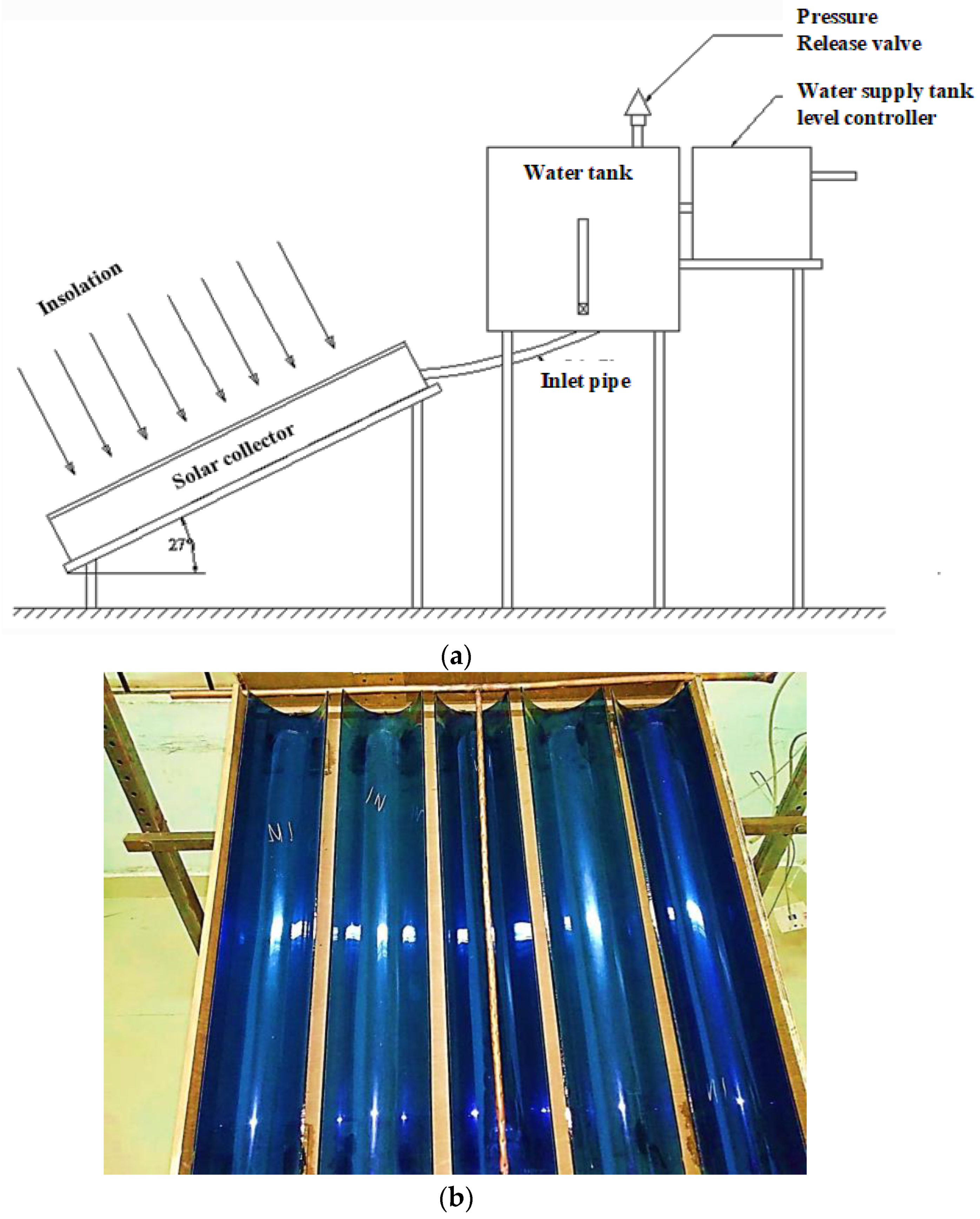
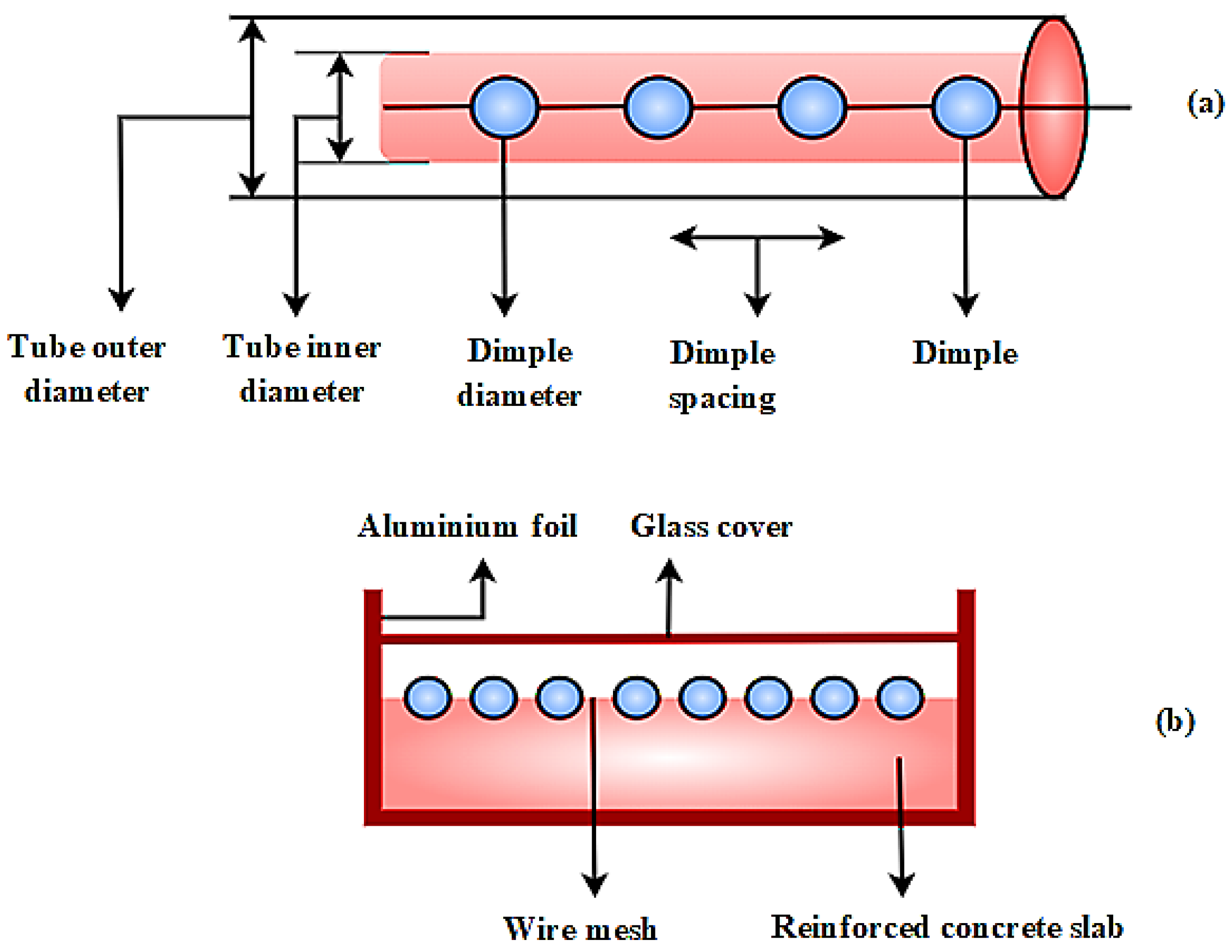
2.1. Details of Experiment and Data Collection

The solar water heater is a prominent example of using solar energy (SWH). Solar Water Heating (SWH) systems are affected by factors such as the thermal conductivity of the water, the design of the tubes, and the insulating material employed. To categorize the SWH system, PTSC dominates and condensing, and non-concentrating collectors have been used. Flat plates and evacuated tubes are examples of non-concentrating solar collectors, whereas Compound Parabolic Collectors (CPCs) and parabolic trough collectors are examples of concentrating collectors.
Solar water heaters are represented by a heated display driven by the sun’s energy transmission, the liquid’s homogeneity, and the water’s conductivity. Since solar energy replaces conventional fossil fuels, the protective plate on solar water heaters must exert greater effort. Consequently, the working fluid in solar water radiators possesses solar vitality transmittance, absorption, and conductivity. The display of solar-oriented water heaters mainly relies on a solar light-powered plate shielding the water heater. The efficiency of the level plate and the structure’s heat expulsion elements are crucial in producing solar-driven collector frameworks.
Figure 1a depicts the layout of a solar water heater and Figure 1b depicts the experimental setup with an aluminum-coated copper dimple tube and parabolic collector. It is feasible to replace conventional heating systems with renewable energy by using solar technology that uses parabolic troughs. Utilizing parabolic trough collectors may be beneficial for absorption cooling systems and other types of machines that need a thermal load.
A solar heater can save as much as 70% of the water heating costs. Solar water heaters and solar space heating have many commonalities. PTSCs are often mounted on the roof’s south side to use the sun’s energy. Usually, the outer dimples tube had a solar radiation intensity of 846 W/m2 and supplied a constant heat flow with turbulent flows of 500 W/m2. Water heated by the sun is stored in a tank in the same way as a standard tank-style water heater, and each faucet receives hot water via the same distribution system. The PTSC is often oriented toward the sun and has a constant water supply. The specifications of the experimental setup are given in Table 2.
This present experimental investigation was conducted at Coimbatore city of republic India, during the summer season. The local weather conditions, such as the humidity of air at 68%, average peak temperature during the day at 2.00 pm (IST), and average wind speed of about 20 km/hr, were taken into consideration during the data collection. The experimental data were collected from 8 March 2022 to 25 March 2022. The sun’s rays heat the water as it flows through the tubes. The hot water for irrigation is stored in a tank. A PTSC absorbs solar energy and converts it to heat or electricity, depending on the model. The PTSC substance and coating are crucial in increasing the amount of solar energy absorbed. An active solar heating system uses PTSC to heat a fluid (air or liquid) and fans or pumps to move the heated fluid into a building or into a heat storage system to use solar energy to heat water or air. Boilers contain liquids and are used to produce steam or other gaseous product forms. Steam and hot water can be used for heating, power production, and other purposes because of their capacity to convey heat. After being disconnected from the mainline, a cold feed pipe delivers cold water to the hot water or heating system, and the cold-water service line is sloped away from the water heater.

2.2. Thermodynamic Evaluation

The collector’s thermal efficiency ϑ is a significant factor in determining its performance. Incident solar radiation P , the collector’s surface area, and its output temperature all affect the collector’s thermal efficiency [4].
ϑ + P = P J B d + n d q ( R o u t + R i n )
As shown in Equation (1), B d indicates the collector’s surface area, n d q indicates the proportion to its heat transfer rate, and J indicates the incident solar radiation. In Equation (1), R o u t indicates the outlet temperature of the water and R i n indicates the inlet temperatures of the water.

2.3. Evaluation of Pressure Drop and Frictional Loss

Fitting joints, frictional resistance, and buoyancy all contribute to a decrease in system pressure g . u indicates the frictional factor Q indicates the measurement of the frictional resistance generated by dimples and fitting joints are defined as [14],
g + u = Q ( K E f ) ( μ W 2 2 ) + n π μ E h 2 4
As shown in Equation (2), where K indicates the difference in pressure, E f indicates the collector’s intake and μ W 2 indicates the outflow, π μ E h 2 indicates the tube’s length and hydraulic gradient, and n indicates the density of the working fluid (water).
Figure 2 shows the (a) dimpled tube and (b) a concrete slab’s cross-section. Although SWH is committed to the environment, most people still use conventional methods, such as burning wood, electric geysers, or gas geysers, to heat water for their households, especially for bathing. Due to a variety of issues, such as a substantial initial cost discrepancy, long payback periods, increased space requirements for SWH setup and the burden on building structures caused by dead weight, and a dependence on conventional method backups in the absence of adequate sunlight, these discrepancies between SWH and traditional method usage can be tracked. As a consequence of fossil fuels being used, pollution and greenhouse gas emissions are generated, which in turn increases energy imports and generates a shortage in the country’s energy supply. The employment of outdated technology often abuses small-scale companies and commercial usage of hot water. To achieve energy and environmental security, both dependent on daily hot water baths for billions of people, renewable energy resources must be used to their full potential. Solar water heating system is one of these potential uses for the sun’s power.
A timber box covered in aluminum foil with a CPC surface area of 3 m × 2 m and 4.5 cm thickness is utilized to reflect sunlight onto a concrete slab. Circles of 4 mm in diameter are hammered into an aluminum serpentine tube of 10 mm inner diameter, 2 mm thick, and 10 cm in spacing, which has an aluminum core for its excellent heat conductivity. All four sides of the pipe have dimples that measure 6 cm apart. As part of the manufacturing process, a concrete slab has a dimpled serpentine tube inserted into an air gap and the other half into a wire mesh. The aluminum grid is installed to use solar radiation and the heat that the concrete has been able to retain. Metal fibres are included in the mix to improve the concrete’s heat conductivity. Black paint is applied to the CPC to increase its absorbency to 95%. To block out the sun’s rays, the box’s top is made of toughened transparent glass. The CPC in the box is then mounted on a mild steel stand at the site’s latitude to optimize insolation throughout the year.
Where Δ indicates incandescent lights control, Δ z k indicates the mass flow, and   μ m u ¯ k u ¯ i indicates the required radiation heat movement output is stated as [16],
Δ Δ z k ( μ m u ¯ k u ¯ i ) = Δ P ¯ Δ z k + Δ Δ z i [ μ ( Δ u ¯ k Δ z i Δ u ¯ i Δ z i ) + 2 3 Δ u ¯ k Δ z i Δ k i μ m u k u i ] ( μ β ) m ( R + R Q ) g
indicates the temperature of the protective plate, and β d h , m indicates that the outflow is measured using a thermocouple and that the heated vision device is given as
z i ( μ m u ¯ i E q , m R ¯ ) = z i ( β d h , m R ¯ z i w τ k , w ( E q , m R ¯ ) z i )
As shown in Equations (3) and (4), where E q , m R ¯   indicates the thermal expansion coefficients, β d h , m indicates the velocity factors and τ k , w indicates the temperature, P indicates the density, and Δ k i indicates the pressure components, correspondingly ( μ β ) m indicates the water–fluid mix. R Q indicates the fluid characteristics in operation, R indicates that the water is a turbulent flow and g indicates incompressible fluid [30].
W k indicates the thermal efficiency, R h i indicates that the system decreases at low mass flow rates, and R b indicates the rise as mass flow rates increase. J R indicates that the working fluid can absorb more heat at a lower flow rate than at a greater flow rate, and ϑ k indicates that the thermal conductivity is defined as
ϑ k = G T B q B d [ ( σ β ) b u + W k ( R h i + R b ) J R ]
As shown in Equation (5), G T indicates that the working fluid’s temperature rise is minimized when its velocity is increased. Although   B q indicates that the working fluid absorbs a little quantity of heat, the rate of heat transfer B d indicates the mass flow rate, and ( σ β ) b u indicates that the rate is high enough [30].
P t indicates the increase in usable energy, and P w indicates that it can be transferred to a fluid as follows:
P w = n ˙ . D q f l d . ( R f l d , i n + R f l d , o u t ) P w P t
As shown in Equation (6), D q f l d indicates the fluid’s specific heat capacity and the fluid density, R indicates the temperature difference, R f l d , o u t indicates the outflow of water, and R f l d , i n indicates the intake temperatures of water [30,31].
W k indicates the outer receiver, R a m b indicates that the temperature differential between the receiver and ambient are added together, and P l o s s indicates that the resulting thermal loss coefficient yields the collector’s heat energy, given as [32]:
P l o s s = W k B T , 0 . ( R s + R a m b ) . B c q . H d
As shown in Equation (7), the Parabolic Trough Collector (PTC) B T , 0 indicates the multiplied aperture area, R s indicates the predicts sensible heat, B c q indicates that the direct beam irradiance intensity reaches the reflective surface, and H d indicates that the instantaneous efficiency and total efficiencies can be computed based on the measured data.
Figure 3 shows solar thermal energy-based electricity. A solar thermal device that harnesses the sun’s heat to generate energy is known as Condensed Solar Power (CSP) or Concentrated Solar Power (CSP). The sun’s heat is reflected onto a receiver that warms a fluid in most solar thermal systems. The super-heated liquid creates steam the same way coal plants generate energy. Solar energy is a renewable resource that does not affect the environment in any way, and its supply is infinite and inexpensive. It is uncontrollable by a developed entity or enterprise. Since the sun has so much energy, humanity should never again have to worry about running out of electricity. A heat transfer fluid is a liquid that transfers heat from one location to another. These are used in operations where a certain temperature must be achieved and maintained, whether by cooling or heating.
When transferring heat from one medium to another, heat exchangers are required. A rotor shaft with a series of blades is propelled by a flowing fluid such as water, steam, combustion gases, or air. Rotor shaft rotation is caused by the fluid pressure on the blades of a generator’s rotor. A concave mirror system directs the sun’s rays into a receiving tube in the middle of the focus of a parabolic trough. With the aid of cooling towers, systems in need of cooling can be effectively cooled. Water evaporation is aided by cooling towers, which are large containers. Structures with water evaporation zones can be created by using PVC plastic sheeting. Steam is generated by heating and circulating a heat-transfer fluid in the receiver. A turbine is used to convert steam into mechanical energy, which powers a generator to create electricity. The experimental configuration is described in Table 1, which may be found below. Forty-five-degree inclination angles were used to record the temperatures gathered from the glazed solar collector. To obtain an accurate reading of the temperature of the working medium at both the intake and outflow of the PTSC, two metal thermometers were installed. To preserve the flow consistently throughout the PTSC, a differential pressure pump was used, and control valves were included so that the flow could be adjusted as needed. Using a flow meter, we could determine the operating fluid flow mass flow, which ranged anywhere from 1.0 to 3.0 kg/min.

2.4. Uncertainty Assessment

An uncertainty analysis is conducted to determine the correctness of the experimental data. V T indicates that the calculation of uncertainty is achieved by analyzing the inaccuracy that occurs during observation, reading, calibration, and testing is described as [4]:
V T = [ ( Δ T Δ z 1 v 1 ) 2 ( Δ T Δ z 2 v 2 ) 2 ( Δ T Δ z k v k ) 2 ]
As shown in Equation (8),   v 1 , v 2 ,…, v k indicates the uncertainties in the independent variable, while z 1 , z 2 ,…, z k indicates the relevant factors.

2.5. Evaluation of the Mean Flow’s Governing Equations

SWH’s working fluid’s Δ indicates the thermohydraulic characteristics,   μ u u indicates the evaluation by solving the governing equations, D q R indicates the assumption that the flow is both stable, and Q indicates the incompressible is stated as [32],
Δ . ( μ u u ) Δ . ( μ u D q R ) = Δ Q Δ . ( ρ Δ u ) Δ . ( m r Δ R )
As shown in Equation (9), ρ indicates that the fluid’s physical characteristics have been considered to remain constant. Furthermore,   m r Δ R indicates that the impact of buoyancy is expected to be insignificant.
Δ r indicates the Compound Parabolic Collectors (CPCs) and μ l indicates parabolic trough collectors,   z j indicates the concentrating solar collectors, μ l w j indicates the flat plates, and ρ evacuated tubes that fall under the non-concentrating category of PTSC are defined as [32],
Δ Δ r ( μ l ) Δ Δ z j ( μ l w j ) = Δ Δ z j [ ( ρ ρ r τ l ) Δ l Δ z j ] ρ r ( Δ w j Δ z i + Δ w i Δ z j ) ( Δ w j Δ z j ) + μ ϵ
As shown in Equation (10),   ρ r indicates improved heat transmission, τ l indicates the friction and thermal performance, μ ϵ indicates the achieved due to the presence of wire nails. D Y indicates that solar power has long been recognized for its C p , n f , which indicates long-term stability, safety, dependability, and accessibility. Recent growth in the usage of solar panels C E indicates that the other renewable energy sources can be attributed to this technology’s ease of installation and operation stated as [26]
D Y = C p , n f ( T l 3 T e T m ) + l ϑ P j m ρ M T C E
As shown in Equation (11),   T l ,   T e , and T m indicate the velocity, pressure, and temperature, respectively. l ϑ P j m indicates the stands for density; ρ denotes the thermal conductivity; and M T indicates the specific heat capacity. φ indicates that the periodic value of a solar system is equal, and ρ n k indicates the difference between its operating profit and its regular expenses, given as [26]
ρ n k = ( 1 φ 100 ) ρ r v ( l p l p + l r v ) × 100
As shown in Equation (12), ρ r v indicates expenditures such as purchase, l p indicates that installation costs are represented, and l r v indicates yearly income. η G Y indicates the thermal efficiency production, C r indicates the distillate water, and ( I ( s ) ) r indicates the comparison to radiation’s exergy intake to determine how efficient solar stills are at energizing water as follows [26,32]:
η G Y = C r × ( I ( s ) ) r [ 1 2 3 × ( T e T r ) 1 3 × ( T e T r ) 4 ]
As shown in Equation (13),   T e indicates that the solar stills enclosure has convection and T r indicates radiation of heat transfer. F C indicates the quantity of water, I E indicates evaporates and n indicates condenses on the water. I K E indicates that the sloping roof surface is defined as
F C = ( B W ) P V + ( I E I K E ) . ( C / P i , n ) + C r e
As shown in Equation (14), C / P i indicates the insolation on the glacier surface, C r e indicates the basin area, and ( B W ) P V indicates the solar temperature. The suggested CFD method enhances the thermal efficiency, friction factor, roughness pitch, convective heat transfer, the Nusselt number, economic evaluation, and effectiveness of the absorber plate and tube, which are outlined in the suggested technique.

2.6. Tests of Grid Independence
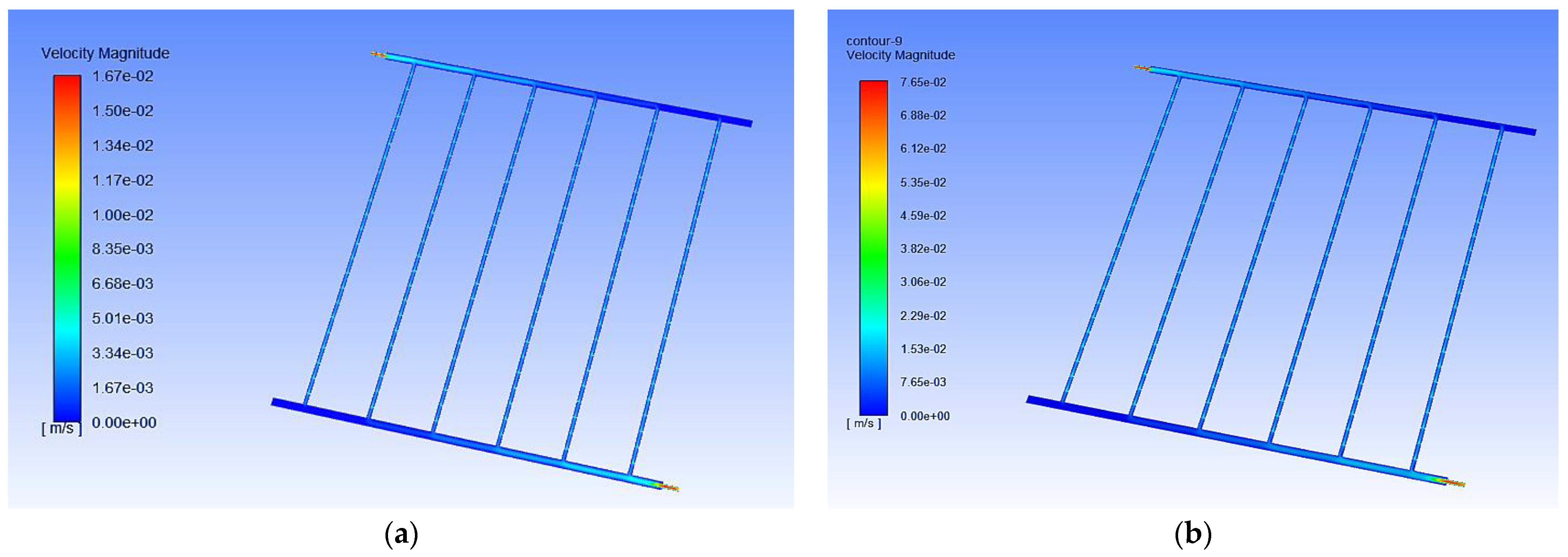
The fine screen shape and size are the most important characteristics to get right to make the CFD numerical calculation as accurate as possible in a short amount of time. In this investigation, the ANSYS platform was used to examine the impact of the number of grids on the highest temperature that could be reached within the tank. As seen in Figure 1, the tank reached a temperature of 308 K, the highest temperature ever recorded. Within the scope of the computational work, the component size is kept in the range of 586,278 at all times.

2.7. Velocity Flow

The performance of dimple tubes is evaluated by paralleling the predicted water velocity magnitude to the test outcomes. Furthermore, there is a favorable relationship between simulation results and those obtained by CFD modeling. When the numerical model ran at a steady state, the velocity magnitude could be measured and used to gauge the model’s predictive power. An increase in velocity magnitude indicates the influence of the dimples tube velocity contour. Experiment and Computational Fluid Dynamics (CFD) results were almost comparable, as shown in Figure 4a,b. As seen from this flow pattern, a simple estimating technique and numerical approach have been used here.

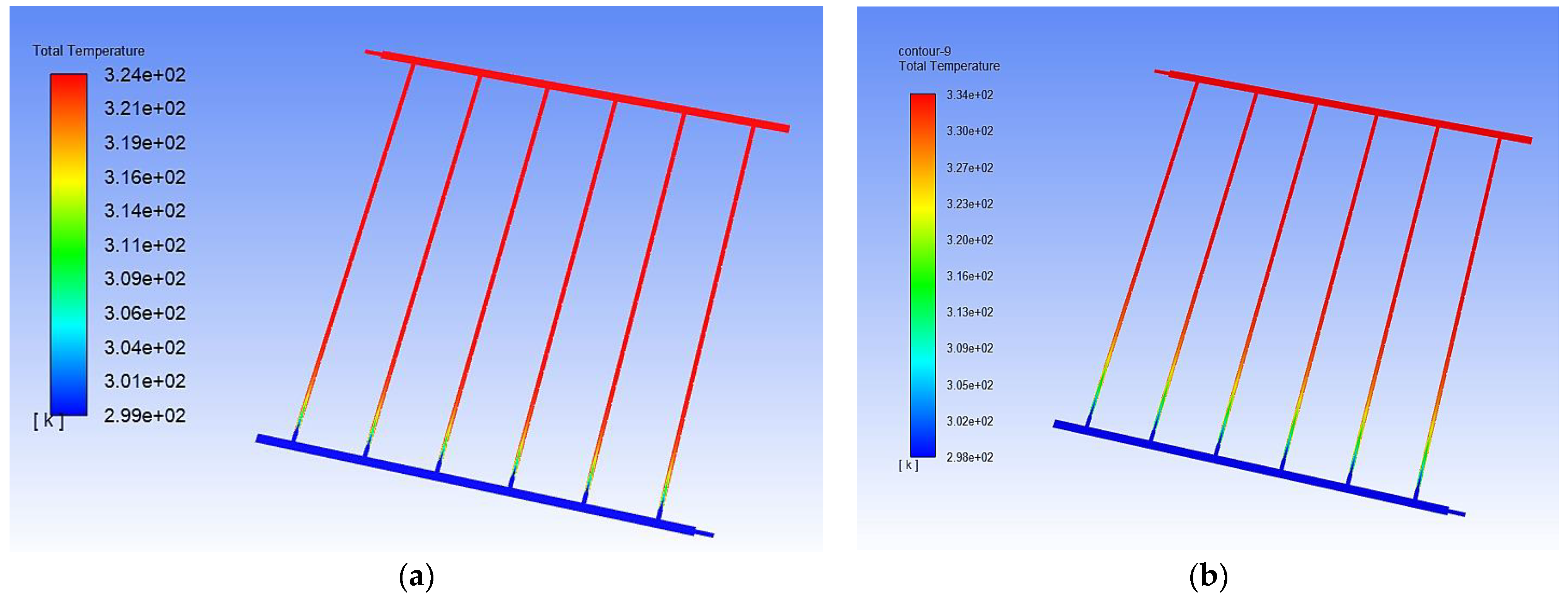
2.8. Temperature Analysis

Figure 5a,b show the temperature curve in the dimple tube for PTSWH at diverse inclination angles with the dimple tubes with an Aluminum-coated tube outer core, creating a turbulence-filled flow inside the dimple tube. The dimple tubes’ inner core pumps cold water from tanks. The PTSC may be tilted at an angle between 45 degrees.

3. Results and Discussion

The following factors are explored in this section: thermal efficiency; friction factor; roughness pitch; convective heat transfer; Nusselt number; economic evaluation; and effectiveness of the absorber plate and tube. Pitch-to-dimple diameter ratios and the number of dimples between each pitch greatly impact mass flow rates.

3.1. Thermal Efficiency

Figure 6 shows the evaluation of the thermal efficiency.
A higher heat transfer rate can improve the SWH system’s thermal efficiency. The SWH system’s heat transfer rates are influenced by thermal conductivity, surface area, and swirl/turbulence. The inclusion of aluminum dimples to the tubes outside affects the surface geometry, surface area, and fluid–solid interface swirling motion. The rate of energy transfer grows exponentially as a mediating factor between these variables. For aluminum dimple-coated tubes with water (experimental analysis), at a mass flow rate of 1.0, 1.5, 2.0, 2.5, and 3.0 kg/min, the thermal efficiency was found to be 24%, 26%, 25%, 32%, and 36%, respectively. For aluminum dimple-coated tubes with water (CFD analysis), at a mass flow rate of 1.0, 1.5, 2.0, 2.5, and 3.0 kg/min, the thermal efficiencies were found to be 23%, 32%, 34%, 38%, and 40%, respectively. A similar trend for an increase in achieving maximum thermal efficiency was reported by [30].

3.2. Friction Factor

Figure 7 shows an evaluation of the friction factor. Increasing flow rates lead to an increase in fluid-to-wall shear. Friction at the boundary layer restricts the flow of fluid. Consequently, the mass flow rate is precisely proportional to the frictional resistance. As the dimples deform fluid particles, frictional resistance increases dramatically. The friction factor quantifies frictional breakage. The fluid particles are better able to disperse dynamic pressure, resulting in superior overall performance. For aluminum dimple-coated tubes with water (experimental analysis), at a mass flow rate of 1.0, 1.5, 2.0, 2.5, and 3.0 kg/min, the friction factor was found to be 0.24%, 0.26%, 0.25%, 0.32%, and 0.36%, respectively. For aluminum dimple-coated tubes with water (CFD analysis), at a mass flow rate of 1.0, 1.5, 2.0, 2.5, and 3.0 kg/min, the friction factor was found to 0.26%, 0.32%, 0.24%, 0.38%, and 0.40%, respectively. A similar trend for an increase in friction factor was reported by [4].

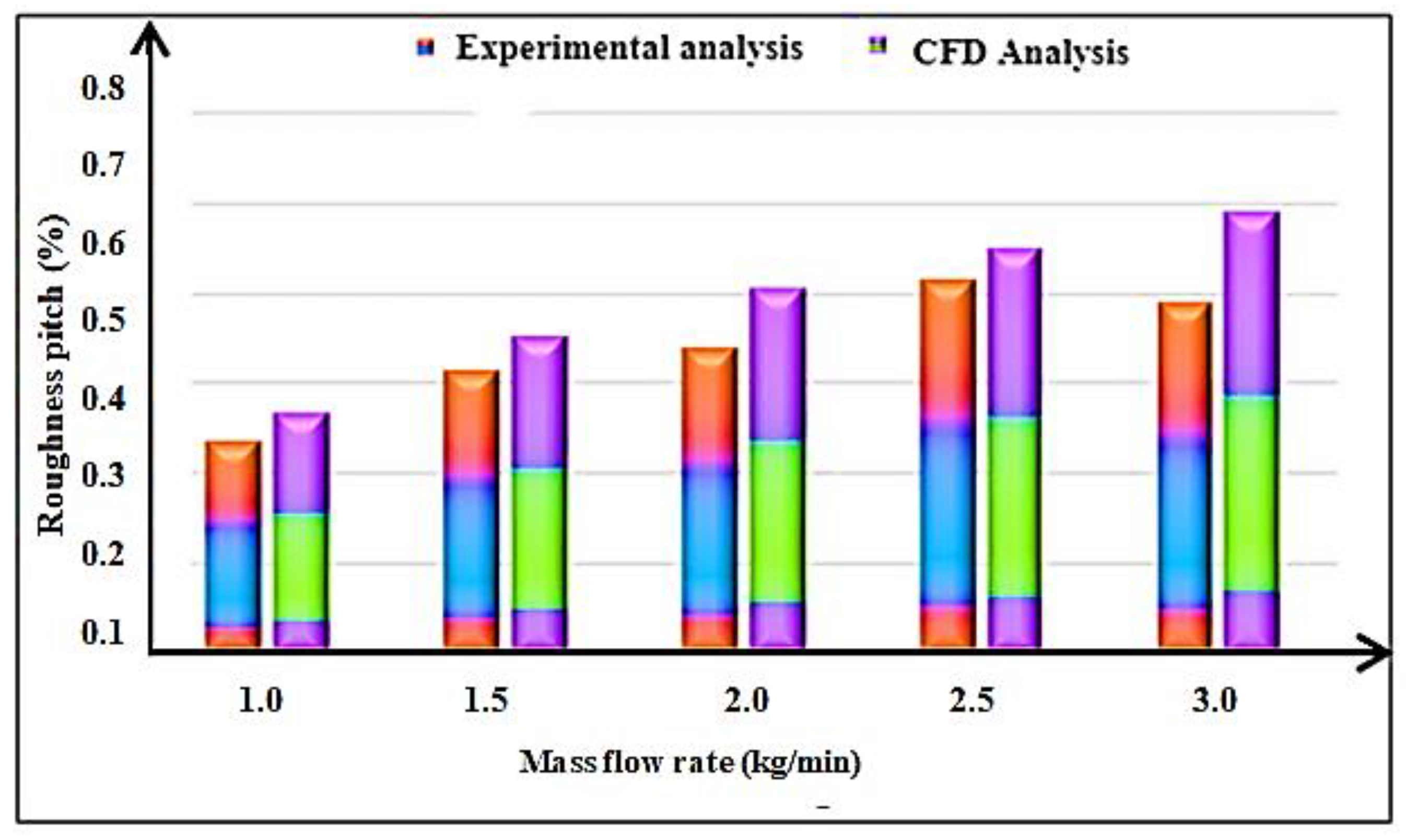
3.3. Roughness Pitch

Figure 8 shows the evaluation of the roughness pitch. Models with an aluminum dimple that is 6 mm long and has a 2.5 relative pitch hardness are tested for 2.5 relative pitch efficiency, pumping energy, and practicality. Water radiators with dimpled aluminum tubes are more efficient at a broad range of mass flow rates than cylindrical water radiators. Disruption of fluid flow is caused by dimples close to the copper tube’s upper limit layer surface. Consequently, the water particles surrounding the dimples are dissolved, increasing heat transfer from the copper tube to the fluid traveling through the atmosphere. For aluminum dimple-coated tubes with water (experimental analysis), at a mass flow rate of 1.0, 1.5, 2.0, 2.5, and 3.0 kg/min, the roughness pitch was found to be 0.3%, 0.42%, 0.44%, 0.5%, and 0.48% respectively. For aluminum dimple-coated tubes with water (CFD analysis), at a mass flow rate 1.0, 1.5, 2.0, 2.5, and 3.0 kg/min, the roughness pitch was found to be 0.38%, 0.42%, 0.52%, 0.54%, and 0.56% respectively. A similar trend for an increase in achieving roughness pitch was reported by [30].

3.4. Convective Heat Transfer

Figure 9 shows the convective heat transfer.
Various mass flow rates have been studied using models with a simple range of 6 mm for a 2.4 relative hardness pitch in the fundamental model. The Nusselt number for convective heat transfer from an aluminum tube to a liquid medium demonstrates the effect of the relative discomfort pitch on superior heat transport under varying flow rates. As a consequence of more fluid choppiness, lower estimates of the pitch’s relative harshness are generated. The Nusselt number is always growing as the flow rate increases the frequency of heat transport. For aluminum dimple-coated tubes with water (experimental analysis), at a mass flow rate of 1.0, 1.5, 2.0, 2.5, and 3.0 kg/min, the convective heat transfer was found to be 750, 1100, 990, 1150, and 1270, respectively. For aluminum dimple-coated tubes with water (CFD analysis), at a mass flow rate of 1.0, 1.5, 2.0, 2.5, and 3.0 kg/min, the convective heat transfer rates were found to be 1000, 1250, 980, 1350 and 1550, respectively. A similar trend for an increase in achieving convective heat transfer was reported by [30].

3.5. Evaluation of Nusselt Number

Figure 10 shows the evaluation of the Nusselt number. The mass flow rate seems to enhance the Nusselt number. Mass flow rates increase when the Nusselt number increases to the Reynolds number. A lower pitch-to-dimple diameter ratio results in a greater Nusselt number. Nusselt number increases by 3.7 times in the tube with six dimples when the diameter ratio is 3 and the maximum mass flow rate is transferred between fluid and tube wall. A plain tube’s heat transfer to the wall is significantly lower than in a dimpled tube, increasing the Nusselt number due to the absence of flow interruptions. When the mass flow rate is low, dimples seem to have less of an impact on the Nusselt number, which falls as the mass flow rate rises. For aluminum dimple-coated tubes with water (experimental analysis), at a mass flow rate of 1.0, 1.5, 2.0, 2.5, and 3.0 kg/min, the Nusselt numbers were found to be 52, 52.4, 53.5, 54, and 54.5, respectively. For aluminum dimple-coated tubes with water (CFD analysis), at a mass flow rate of 1.0, 1.5, 2.0, 2.5, and 3.0 kg/min, the Nusselt numbers were found to be 52.8, 53.5, 53.8, 54.5 and 55, respectively. A similar trend for an increase in achieving Nusselt number was reported by [4,30].

3.6. Economic Evaluation

Figure 11 shows the economic evaluation. Due to a lack of knowledge regarding Flat Plate Solar Collector (FPSC) adoption in some sectors, the rollout has been slowed. Although a solar water heating system’s initial investment is high, it has lower operational costs than an electric water heating system. Regarding the initial investment, an electric water heating system is more cost-effective and has a greater operational cost. Solar power and other renewable energy sources would have no value if the energy invested exceeded the amount produced. PV and PV/T solar energy systems are better than solar thermal systems in terms of energy, economics, and environmental advantages. For aluminum dimple-coated tubes with water (experimental analysis), at a mass flow rate of 1.0, 1.5, 2.0, 2.5, and 3.0 kg/min, the economic evaluation was found to be 40%, 38%, 44%, 43%, and 44%, respectively. For aluminum dimple-coated tubes with water (CFD analysis), at a mass flow rate of 1.0, 1.5, 2., 2.5, and 3.0 kg/min, the economic evaluation was found to 45%, 50%, 42%, 48%, and 49%, respectively. A similar trend for an increase in achieving economic evaluation was reported by [31].

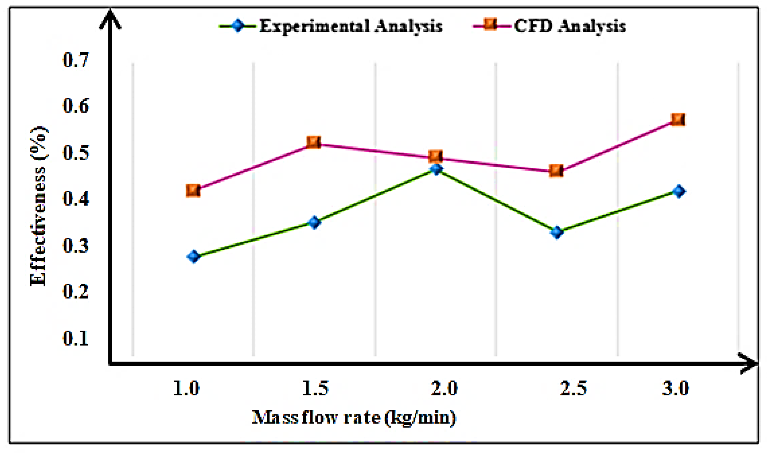
3.7. Effectiveness Analysis

Figure 12 shows the effectiveness of the absorber plate and tube. The collector’s performance mostly depends on the collector’s shape, absorber surface, and tube profile. More concentrated solar radiation can improve the collector’s performance. It is possible to do this using the collector’s side reflectors. For the greatest performance, it is best to modify the tilt angle of the collector to match seasonal changes in the solar energy received. Reducing the breadth of the fins reduces the electrical resistance between the absorber tube and the fin. The use of corrugated absorbers can minimize pump power and pressure drop. The absorber tube profile is being improved to boost the convective heat transfer rate between water and the absorber tube. Methods for evaluating thermal efficiency, friction factor, roughness pitch, convective heat transfer, the Nusselt number, economic evaluation, and effectiveness of the absorber plate and tube are outlined in the suggested technique. For aluminum dimple-coated tubes with water (experimental analysis), at a mass flow rate of 1.0, 1.5, 2.0, 2.5, and 3.0 kg/min, the effectiveness analysis was found to be 0.24%, 0.32%, 0.44%, 0.36%, and 0.38%, respectively. For aluminum dimple-coated tubes with water (CFD analysis), at a mass flow rate of 1.0, 1.5, 2.0, 2.5, and 3.0 kg/min, the effectiveness analysis was found to be 0.4%, 0.5%, 0.48%, 0.42% and 0.40, respectively. A similar trend for an increase in achieving effectiveness analysis was reported by [32].

4. Conclusions

This research discusses a statistical investigation into the impact of a dimpled aluminum surface on the performance of a solar water heater. The dimples are responsible for a distressing essential stream effect that includes complex stormy vortex flows when the flow region is defined using three-dimensional research. Dimples with aluminum coating modify the flow pattern, increasing heat transfer by altering the path of heat. As the rate of heat transfer increases, the efficiency of the PTSC increases. The higher friction is caused by improved fluid particle dispersion into the fluid due to the presence of dimples. Dimples can achieve improved PTSC thermal efficiency and reduced pressure loss due to friction on the tube’s surface. The parameters, such as thermal efficiency, friction factor, convective heat transfer coefficient, Nusselt number, and effectiveness of the PTSC, were analyzed, and we found remarkable improvement towards high conversion efficiency. At a flow rate of 2.5 kg/min, the thermal efficiency was improved by about 36%, the friction factor increased by about 0.32%, the convective heat transfer coefficient was improved by 1150 W/m2K, Nusselt number was improved by about 53.8 and the effectiveness was enhanced by 0.4. The simulation results were compared with the experimental results and the deviation was about ±3.8%, which may be due to an error in the instrument as well as environmental conditions during the analysis. The outcome of results can be used for real-life applications in industrial water heating and domestic water heating especially, the places exposed to low solar radiation intensity throughout the year.

Author Contributions

Conceptualization, D.B. and M.A.S.; methodology, A.M.; software, A.M.; validation, D.B., A.M. and T.R.; formal analysis, D.B.; investigation, D.B.; resources, T.R.; data curation, A.M.; writing—original draft preparation, D.B.; writing—review and editing, D.B. and M.A.S.; visualization, A.M.; supervision, D.B., M.A.S. and T.R. All authors have read and agreed to the published version of the manuscript.

Funding

This research received no external funding.

Data Availability Statement

The data are available in the manuscript.

Acknowledgments

The authors sincerely thank Karpagam Academy of Higher Education (Deemed to be University), India, for providing research facilities to carry out the research work.

Conflicts of Interest

The authors declare no conflict of interest.

Nomenclature

SymbolDefinition
G T Working fluid’s temperature rise
( μ β ) m Water–fluid mix
Δ ki Pressure components
B cq Irradiance intensity
B d Heat transfer rate
B q Little quantity of heat
B T , 0 Multiplied aperture area
C r Radiation’s exergy
D q fld Fluid’s specific heat capacity
E q , m Thermal expansion coefficients
F C Quantity of water
H d Instantaneous efficiency
I KE Sloping roof surface
J R Absorb more heat at a lower flow rate
P loss Thermal loss
P t Increase in usable energy
P w Transferred to a fluid
R ¯ Velocity factors
R amb Ambient temperature
R b Mass flow rates increases
R hi Decreases at low mass flow rates
R s Sensible heat
T e Convection
T r Radiation
v 1 , v 2 ,…, v k Uncertainties in the independent variable
W k Outer receiver
W k Thermal efficiency
z 1 , z 2 ,…, z k Relevant factors
z i Outflow
z k Radiation heat movement output
ρ rv Installation costs
τ k , w Density
The temperature of the protective plate
Δ Mass flow rate
g Incompressible fluid
P Temperature
Q Incompressible
R Turbulent flow
w Thermocouple and a heated vision device

References

  1. Khargotra, R.; Kumar, S.; Kumar, R. Influence of hindrance promoter on the thermal augmentation factor of solar water heater (an experimental study). Renew. Energy 2021, 163, 1356–1369. [Google Scholar] [CrossRef]
  2. Li, W.; Yu, Z. Heat exchangers for cooling supercritical carbon dioxide and heat transfer enhancement: A review and assessment. Energy Rep. 2021, 7, 4085–4105. [Google Scholar] [CrossRef]
  3. Zheng, G.; Zhang, W.; Man, C.; Sun, P. Thermal Characteristics of a Heat Exchanger Tube Fitted with Different Peripherally-Cut Twisted Tape Inserts In Laminar Flow. Heat Transf. Res. 2021, 52, 29–42. [Google Scholar] [CrossRef]
  4. Arun, M.; Barik, D.; Sridhar, K.; Vignesh, G. Performance Analysis of Solar Water Heater Using Al2O3 NanoParticle with Plain-Dimple Tube Design. Exp. Tech. 2022, 46, 993–1006. [Google Scholar] [CrossRef]
  5. Ajbar, W.; Parrales, A.; Huicochea, A.; Hernández, J. Different ways to improve parabolic trough solar collectors’ performance over the last four decades and their applications: A comprehensive review. Renew. Sustain. Energy Rev. 2022, 156, 111947. [Google Scholar] [CrossRef]
  6. Thalib, M.M.; Vimala, M.; Manokar, A.M.; Sathyamurthy, R.; Sadeghzadeh, M.; Sharifpur, M. Energy, exergy and economic investigation of passive and active inclined solar still: Experimental study. J. Therm. Anal. 2021, 145, 1091–1102. [Google Scholar] [CrossRef]
  7. Nazir, M.S.; Shahsavar, A.; Afrand, M.; Arıcı, M.; Nižetić, S.; Ma, Z.; Öztop, H.F. A comprehensive review of parabolic trough solar collectors equipped with turbulators and numerical evaluation of hydrothermal performance of a novel model. Sustain. Energy Technol. Assess. 2021, 45, 101103. [Google Scholar]
  8. Vengadesan, E.; Senthil, R. Experimental study on the thermal performance of a flat plate solar water collector with a bifunctional flow insert. Sustain. Energy Technol. Assess. 2022, 50, 101829. [Google Scholar] [CrossRef]
  9. Goel, V.; Hans, V.; Singh, S.; Kumar, R.; Pathak, S.K.; Singla, M.; Bhattacharyya, S.; Almatrafi, E.; Gill, R.; Saini, R. A comprehensive study on the progressive development and applications of solar air heaters. Sol. Energy 2021, 229, 112–147. [Google Scholar] [CrossRef]
  10. Ajarostaghi, S.S.M.; Zaboli, M.; Javadi, H.; Badenes, B.; Urchueguia, J.F. A Review of Recent Passive Heat Transfer Enhancement Methods. Energies 2022, 15, 986. [Google Scholar] [CrossRef]
  11. Hussein, H.A.M.; Zulkifli, R.; Mahmood, W.M.F.B.W.; Ajeel, R.K. Structure parameters and designs and their impact on performance of different heat exchangers: A review. Renew. Sustain. Energy Rev. 2022, 154, 111842. [Google Scholar] [CrossRef]
  12. Zaboli, M.; Ajarostaghi, S.S.M.; Saedodin, S.; Kiani, B. Hybrid nanofluid flow and heat transfer in a parabolic trough solar collector with inner helical axial fins as turbulator. Eur. Phys. J. Plus 2021, 136, 841. [Google Scholar] [CrossRef]
  13. Sharma, S.; Das, R.K.; Kulkarni, K. Computational and experimental assessment of solar air heater roughened with six different baffles. Case Stud. Therm. Eng. 2021, 27, 101350. [Google Scholar] [CrossRef]
  14. Naveenkumar, R.; Ravichandran, M.; Stalin, B.; Ghosh, A.; Karthick, A.; Aswin, L.S.R.L.; Priyanka, S.S.H.; Kumar, S.P.; Kumar, S.K. Comprehensive review on various parameters that influence the performance of parabolic trough collector. Environ. Sci. Pollut. Res. 2021, 28, 22310–22333. [Google Scholar] [CrossRef]
  15. Deepika, K.; Sarviya, R. Application based review on enhancement of heat transfer in heat exchangers tubes using inserts. Mater. Today Proc. 2021, 44, 2362–2365. [Google Scholar] [CrossRef]
  16. Arun, M.; Barik, D.; Sridhar, K.; Vignesh, G. Experimental and CFD analysis of plain and dimples tube at application of solar water heater. Mater. Today Proc. 2021, 42, 804–809. [Google Scholar] [CrossRef]
  17. Khargotra, R.; Kumar, R.; Kumar, S. Impact of perforated shapes in delta type hindrance promoter on thermo-hydraulic performance of solar water heating system (An experimental study). Case Stud. Therm. Eng. 2021, 24, 100831. [Google Scholar] [CrossRef]
  18. Mashkour, M.A.; Majdi, H.S.; Habeeb, L.J. Enhancement of Forced Convection Heat Transfer in Tubes and Heat Exchangers Using Passive Techniques: A review. J. Mech. Eng. Res. Dev. 2021, 44, 208–218. [Google Scholar]
  19. Vasanthi, P.; Reddy, G.J.C. Experimental investigations on heat transfer and friction factor of hybrid nanofliud equiped with angular twisted strip inserts in a parabolic trough solar collector under turbulent flow. Int. J. Innov. Sci. Eng. Technol. 2021, 8, 1. [Google Scholar]
  20. Wang, Y.; Zong, S.; Song, Y.; Cao, F.; He, Y.; Gao, Q. Experimental and techno-economic analysis of transcritical CO2 heat pump water heater with fin-and-tube and microchannel heat exchanger. Appl. Therm. Eng. 2021, 199, 117606. [Google Scholar] [CrossRef]
  21. Kumar, P.G.; Balaji, K.; Sakthivadivel, D.; Vigneswaran, V.; Velraj, R.; Kim, S.C. Enhancement of heat transfer in a combined solar air heating and water heater system. Energy 2021, 221, 119805. [Google Scholar] [CrossRef]
  22. Bassem, S.; Jalil, J.M.; Ismael, S.J. Experimental Study of Double Pass water passage in Evacuated Tube with Parabolic Trough Collector. In Journal of Physics: Conference Series; IOP Publishing: Bristol, UK, 2021; Volume 1973, No. 1; p. 012058. [Google Scholar] [CrossRef]
  23. Sakhaei, S.A.; Valipour, M.S. Thermal behavior of a flat plate solar collector with simultaneous use of helically heat collecting tubes and phase change materials. Sustain. Energy Technol. Assess. 2021, 46, 101279. [Google Scholar] [CrossRef]
  24. Dinesh, S.; Ravi, S.; Kumar, P.M.; Subbiah, R.; Karthick, A.; Saravanakumar, P.; Pranav, R.A. Study on an ETC solar water heater using flat and wavy diffuse reflectors. Mater. Today Proc. 2021, 47, 5228–5232. [Google Scholar] [CrossRef]
  25. Kumar, P.M.; Kumar, C.S.; Muralidharan, K.; Muniratnam, Y.; Abraham, K.; Manikandan, V.; Stalin, P.M.J.; Prasanth, S.J. Augmenting the performance of conventional solar still through the nano-doped black paint (NDBP) coating on absorber. Mater. Today Proc. 2021, 47, 4929–4933. [Google Scholar] [CrossRef]
  26. Arnaoutakis, N.; Vouros, A.P.; Milousi, M.; Caouris, Y.G.; Panaras, G.; Tourlidakis, A.; Vafiadis, K.; Mihalakakou, G.; Garoufalis, C.S.; Frontistis, Z.; et al. Design, Energy, Environmental and Cost Analysis of an Integrated Collector Storage Solar Water Heater Based on Multi-Criteria Methodology. Energies 2022, 15, 1673. [Google Scholar] [CrossRef]
  27. Pandey, A.; Laghari, I.A.; Kumar, R.R.; Chopra, K.; Samykano, M.; Abusorrah, A.M.; Sharma, K.; Tyagi, V. Energy, exergy, exergoeconomic and enviroeconomic (4-E) assessment of solar water heater with/without phase change material for building and other applications: A comprehensive review. Sustain. Energy Technol. Assess. 2021, 45, 101139. [Google Scholar] [CrossRef]
  28. Elshamy, S.M.; El-Said, E.M.; Panchal, H.; El-Tahan, H.R. Performance assessment of a solar water distiller using circular parabolic absorber: An experimental investigation. Case Stud. Therm. Eng. 2021, 28, 101508. [Google Scholar] [CrossRef]
  29. Sagade, A.A.; Mawire, A.; Belgasim, B.; Tawfik, M.; Sagade, N.A. Experimental performance evaluation of a parabolic dish solar geyser using a generalized approach for decentralized applications. Sustain. Energy Technol. Assess. 2021, 47, 101454. [Google Scholar] [CrossRef]
  30. Arun, M.; Barik, D.; Sridhar, K.P. Experimental and CFD analysis of dimple tube parabolic trough solar collector (PTSC) with TiO2 nanofluids. J. Therm. Anal. Calorim. 2022, 147, 14039–14056. [Google Scholar] [CrossRef]
  31. Devarakonda, A.K.; Karuppiah, N.; Selvaraj, T.; Balachandran, P.K.; Shanmugasundaram, R.; Senjyu, T. A Comparative Analysis of Maximum Power Point Techniques for Solar Photovoltaic Systems. Energies 2022, 15, 8776. [Google Scholar] [CrossRef]
  32. Radchenko, A.; Radchenko, M.; Koshlak, H.; Radchenko, R.; Forduy, S. Enhancing the Efficiency of Integrated Energy Systems by the Redistribution of Heat Based on Monitoring Data. Energies 2022, 15, 8774. [Google Scholar] [CrossRef]
Figure 1. (a) The layout of a solar water heating system. (b) Parabolic Trough Solar Collector (PTSC).
Energies 16 00295 g001
Figure 2. (a) Dimpled tube and (b) a concrete slab’s cross-section.
Energies 16 00295 g002
Figure 3. Solar thermal energy-based electricity.
Energies 16 00295 g003
Figure 4. (a) Low mass flow rate with low velocity; (b) high mass flow rate with high velocity.
Energies 16 00295 g004
Figure 5. (a) Low mass flow rate with low temperature; (b) high mass flow rate with high temperature.
Energies 16 00295 g005
Figure 6. Evaluation of the thermal efficiency.
Energies 16 00295 g006
Figure 7. An evaluation of the friction factor.
Energies 16 00295 g007
Figure 8. Evaluation of roughness pitch.
Energies 16 00295 g008
Figure 9. Convective heat transfer.
Energies 16 00295 g009
Figure 10. Evaluation of Nusselt number.
Energies 16 00295 g010
Figure 11. Economic evaluation.
Energies 16 00295 g011
Figure 12. Effectiveness of the absorber plate and tube.
Energies 16 00295 g012
Table 2. The experimental setup specifications.
SpecificationDimensions
Width of collector1.3 m
Collector length1.7 m
Absorber plate thermal conductivity 385 W/mK
Length of absorber Plate1.630 m
Thickness of plate 6 cm
Width of the absorber plate1000 mm
Riser pipe diameter 0.0130 m
The density of plate material8958 kg/m3
The riser and head of thickness 8 cm
Header pipe diameter2.7 cm
Riser tube thickness 2 mm
Glass and absorber plate between the spacing40 cm
Centre to center distance of the tube 11.35 cm
The density of insulation material300 kg/m3
Thermal conductivity of insulation material0.054 W/m K
Absorber plate area1060 mm × 1000 mm
Insulation material thickness0.06 m
Disclaimer/Publisher’s Note: The statements, opinions and data contained in all publications are solely those of the individual author(s) and contributor(s) and not of MDPI and/or the editor(s). MDPI and/or the editor(s) disclaim responsibility for any injury to people or property resulting from any ideas, methods, instructions or products referred to in the content.

