Abstract
CPC solar collectors are a combination of new technologies that make it possible to generate heat from radiant solar energy by transferring heat between the absorber and the fluid. This study was performed based on heat transfer equations by proposing a mathematical model, as reported in the literature. A compound parabolic concentrators solar collector (CPC) numerical model was simulated and coded in Aspen HYSYS and MATLAB software and validated by comparing its results with other researchers and experimental results. The simulated mathematical model includes a two-dimensional numerical model to describe the thermal and dynamic behavior of the fluid inside the CPC solar collector absorber tube. Numerical simulations of the fluid flow equations inside the CPC solar collector absorber tube, along with the energy equation for the absorber tube wall, coating, insulation and reflector, and solar collector heat analysis, were performed repeatedly in MATLAB and Aspen HYSYS software. This method is the most appropriate and reliable method for solving equations for numerical convergence. The experimental results of the parabolic concentrated solar collector (CPC) were used to evaluate and validate the numerical model. A solar compound parabolic concentrators collector (CPC) with short reflectors was used. This collector includes a cylindrical absorber with a real density ratio of 1.8, a reception angle of 22 degrees and a length of 2.81 m, a width of 0.32 m, and an opening of 0.1764 m. Analysis and uncertainty of the proposed model were performed with the measured sample. In the thermal efficiency analysis, the average deviation of the model from the experimental results of other researchers was equal to 7%, for increasing the temperature by 9 °C. According to these results, a good correlation between numerical results and experimental results for this proposed model has been obtained.
1. Introduction
Originally used as radiation detectors in the early 1960s, compound parabolic concentrator solar collectors are more than 50 years old. Initially, Winston and Heinterberger described their use as sun-oriented collectors (1975) [1]. This technology has developed over time until solar water heaters became widely used. Using a flat solar receiver, a preliminary study was conducted on CPC solar collector technologies. Through advancements in technology, the receivers evolved to become tubes, which made it possible to use fluid as a heat transfer fluid [2]. The average reflection of solar radiation into the CPC solar collectors has been calculated analytically by Rübel (1976). CPC solar collectors were analyzed optically using the results of this study [3]. Using thermal analysis for solar collectors with absorber tubes, Hsieh (1981) developed a mathematical model [4]. A CPC collector absorber tube was modeled with the finite element method by Chew et al. (1989), There was an isothermal coating on the absorber tube. Y. Trip Anagnostopoulos et al. (2000) designed two-faced solar collectors and presented them as CPC systems. According to the experimental findings, the proposed compound parabolic concentrator collector can achieve a maximum static temperature of 180 °C and an efficiency of 0.71 [5]. An axial heat flux solar collector was studied by China et al. (2006). Furthermore, Kim et al. (2008) designed and manufactured their own discharged-tube solar collectors, which they theoretically and experimentally evaluated [6]. Solar collectors with a tracking system that allows for a stable trajectory had a thermal Solar collector whose CPC had a 14.9% higher efficiency. An experimental solar collector based on CPC technology was proposed by Y. Kim et al. (2010). Its prototype accomplished a return of over 50% [7]. T. Beikircher et al. (2011) used geometrical concentration to investigate the optical performance of CPC solar collectors. After conducting simulation analyses, it was determined that the operating temperature was 0.35 degrees Celsius greater than the temperature of a flat plate collector [8] C. Tba and N. Fraidenraich (2013) employed a compound parabolic concentrator solar collector to activate a cooling system generator in a solar cooling project. CPC solar collectors achieved a temperature of 125 °C and an efficiency of 0.50 [9]. In their study, Z. S. Lu et al. (2013) developed and analyzed a numerical code for simulating the thermal behavior of storage systems with CPC solar collectors. It was determined that double glazing could increase efficiency by up to 47% by using it as a coating [10]. CPC solar collectors presented by C. Tíba and N. Fraidenraich, (2013) with U-shaped drained pipes reached an efficiency of up to 0.50 and a temperature of 150 °C [9]. Researchers at Gu et al. (2014) achieved a temperature range from 300 °C to 500 °C for a vacuum CPC solar collector [11]. Incorporating CPC solar collectors thermal and photovoltaic system was presented by X. Gu et al. (2014). A 5% difference in the results of the theoretical and experimental evaluations was found between these CPC solar collectors [12]. Figure 1 shows a CPC collector.
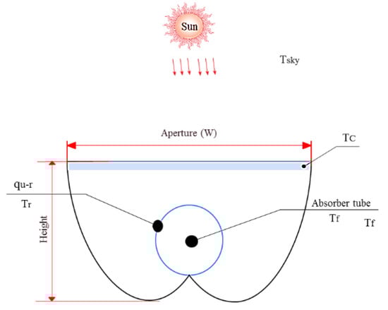
Figure 1.
CPC collector [13].
Recently, researchers have looked at improving the performance of CPC concentrators by modifying their geometry, such as using materials that are better at transmitting light, creating better operating conditions, and using discharged tubes as adsorbents. Compared to the vacuum tube manufacturing process, it is easier and cheaper to make these other improvements. Table 1 summarizes the research conducted CPC solar collectors.

Table 1.
Summary of research on CPC collectors.
This paper compares the mathematical relationships of a CPC with a tubular absorber with the practical results of a CPC collector. A mathematical model was developed and simulated in Span Hayes and MATLAB software, and a comparative study was performed between the results of the simulated CPC composite with the real sample and the samples of other researchers. In the solar collector, industrial oil is used as heat transfer fluid
2. Materials and Methods
2.1. Modeling of CPC Collectors
To calculate and design parabolic solar collectors, a Cartesian plane is used in which the two main parts of the geometry are drawn in a curve and a parabola based on the dimensions of the absorber tube [45,46]. For restricting the shape of CPC solar collectors in relation to angle, Baum (1984) proposed equations measured by rotating the absorber tube around its center point counterclockwise from the positive x-axis [47]. These equations can be used to calculate the geometry of CPC solar collectors in the coordinate plane, as well as their curves for parts in the plane and parabolas.
To:
To:
To:
With the values obtained on the Cartesian plate, the areas of coverage, reflectivity, and absorbency can be determined. The equations of coverage, absorber, and reflector are:
Aa refers to the diaphragm area, Ar to the lateral area of the receiver tube, and L to the length of the collector. The external absorption tube of CPC solar collectors made of 2.81 m has an inner diameter of 1.90 cm. Due to their large reception angle, CPC solar collectors combine solar radiation despite their lack of concentration. θ1/2 = 20 is the angle between the openings of the solar collectors. The vertical axis is the angle between the CPCs. CPC solar collectors were designed using θ = 2.2 and a cut of 0.5 of the height of the reflectance area. Carvalho et al. (1985) showed that incisions can result in significant gains in optical quality [48]. In particular, it increases the reception of the scattered beams and beams and reduces the average number of reflections. In addition, fewer materials are needed to make CPC solar collectors. After cutting, the acceptance half angle was θ1/2 = 22 degrees. By this method, a 0.32 m wide and 0.29 m high CPC collector can be designed. The specified length for CPC solar collectors is 2.81 m. Figure 2 shows a CPC collector.
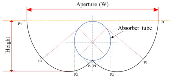
Figure 2.
CPC solar collector [49].
CPC solar collectors with a Security glass coating are mathematically designed and modeled to cover the reflective surface and protect the environment. In Figure 2, we show schematically how to assemble the CPC solar collectors. A polystyrene insulating material was used that was coated with a resin for protection and strength. The polystyrene was glued to the reflective foil with special glue. An absorber tube is made of stainless steel, which is covered in matte black selective absorbers. The cover was constructed of Security glass and was attached to a framework that covered the edges of the solar collector with an aluminum frame. In order to test it, it must be put in a fixed position.
2.2. Simulation and Mathematical Modeling
The investigation of CPC solar collectors is based on a theory proposed by numerous authors. The mathematical model was created. When the CPC solar collectors are shortened, the reflector level is dropped by half, yet the composite performance stays about the same [4,50,51]. The correlations utilized in the mathematical model to evaluate the performance of incandescent (shortened) CPC solar collectors were expected to be applicable to sectional (abbreviated) parabolic solar collectors [52].
In Figure 3, the solar input flux is received by the absorber plate and the glass cover. Part of the heat absorbed by the outer part of the absorber plate surface is transferred to the inner part of the surface through the heat transfer mechanism and then to the working fluid through the heat transfer mechanism and the rest is transferred to the inner surface by heat transfer and radiation. The glass cover is transferred. The energy transmitted through displacement and radiation to the inner surface of the glass coating is first transferred to the outer surface by conduction and then wasted to the environment through radiation and displacement.
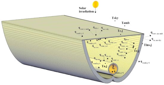
Figure 3.
Heat distribution of CPC solar collectors.
Figure 4 and Figure 5 of the network show the heat transfer mechanisms of CPC solar collectors. This network has been suggested for the analysis of solar collectors. The solar energy absorbed in the absorber tube of the solar collector increases the temperature of the tube. There are five main temperatures in the heat transfer process shown. These temperatures are fluid, adsorbent, coating, reflector, and environment.
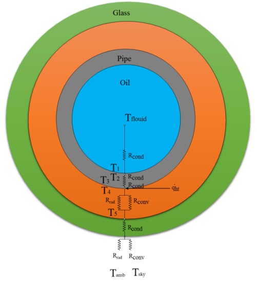
Figure 4.
Heat transfer network of CPC solar collectors.
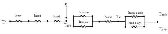
Figure 5.
Heat transfer network of CPC solar collectors for mathematical modeling.
Since CPC solar collectors are exposed to environmental conditions, CPC solar collectors are affected by environmental conditions, and energy is transferred from the collector to the environment. The absorbed solar energy is transferred to the absorber tube and from the absorber tube to the working fluid, which increases the temperature of the working fluid in the absorber tube and the fluid leaving the solar collector [53]. The following hypotheses are considered to analyze the thermal behavior of the CPC solar collector:
- Constant heat transfer.
- At the end of each depression, there is a slight conduction drop.
- Low iron glass coating with non-specific permeability is 0.90.
- One-dimensional flow is considered.
- The material of the reflector sheets is steel and its reflection coefficient is 0.9.
- The collector adsorbent is a corrosion resistant steel with an absorption coefficient of 0.94.
- It is considered zero by the absorption of solar radiation.
- The geometry of CPC solar collectors is without manufacturing errors.
- In the environment around the CPC solar collector, the thermodynamic properties, heat fluxes, and all temperatures are uniform.
- In a solar collector absorber tube, the heat resistance is negligible and neglected.
Radiation rays reach the absorber tube in several ways [54]. A portion of the rays entering the aperture from different directions of the light source reach the absorber tube directly, and after one or more reflections, the other rays reach the absorber tube. Hence, we can define an average radiation reflectance (n) for CPC solar collectors. Optical efficiency in the construction of solar collectors was estimated according to the materials used in an experimental study presented by Oommen and Jayaraman (2001) [55]. This method makes it possible to estimate the solar radiation in the absorber tube [56]. The relationship between the estimated optical efficiency is as follows.
where τc crosses the cover. αa is the lack of adsorbent. p is the reduction coefficient of the opening. Its formula (1 − g/2πro) in the formula the thickness of the gap is g (here, g = 1.00 cm was considered). is the effective transmission of the CPC solar collectors. Here, ρ is the solar reflection of the reflective material of the CPC solar collectors. In Formula (10), the average number of reflections is obtained from the following equation:
here:
Fluid outlet temperature is equal to:
To predict the collector performance,, which represents the collector efficiency coefficient, must be calculated. To evaluate the energy survival in the solar collector according to the fluid inlet temperature, the removal factor of the solar collector is used. Given that the highest value of high temperature can not be defined on the surface of the adsorbent tube, Equation (14) is used [57]:
Here, without considering the heat transfer mechanism in the fluid, the heat transfer coefficient of all CPC solar collectors is calculated. The method uses the relationship between the experimental expression proposed by Duffy and Beckman 1991. The coefficient of heat transfer losses of the solar energy receiver is calculated from Formula (15). Here is the total coefficient of heat loss [58]:
Heat transfer between hot and enclosed air and the radiation receiver tube is referred to as internal heat transfer, and its value is obtained by the formula of instantaneous energy balance on the receiver tube [59,60].
where is the solar energy passing through the glass coating and is the absorption coefficient of the glass coating and is the absorption coefficient of the receiver.
where the convective heat transfer coefficient is and is calculated from Formula (18) [61,62].
In the above formulas, the convective heat transfer coefficient between the environment and the glass coating is displayed with and is calculated from the following formula. Duffy and Beckman (1991) calculated the convective heat transfer coefficient between the environment and the glass coating [63]. The radiation heat transfer coefficient is calculated using the following equation [62,64,65].
In the formulas, the wind speed is V. The equations presented by Hsieh (1981) were used to calculate the convective heat transfer coefficient between the reflector and the absorber tube and the cover and the adsorbent tube [4]:
Given that the input of the current collector is considered to be fully developed, the outer diameter of the receiver tube of the solar collector is [66].
where the average temperature of the receiver tube is Tr and the radiant heat transfer coefficient is .
On the collector cover, heat transfer occurs between the glass and the environment, which is the external heat transfer, in the form of various independent forms of heat transfer, such as convection and radiation, which is a large amount of heat loss. The instantaneous energy balance formula on the composite parabolic collector glass cover is as follows:
where the CPC solar collector glass cover is absorbed by the absorption coefficient and is the amount of radiant solar energy.
where the radiant heat transfer coefficient is [67]. According to Hsieh (1981), the radiative heat transfer coefficient between the reflector and the absorber, the coating and the absorber, the coating and the reflector, the cover and the sky, can be evaluated by the following equations [64,65]
is the diffusion coefficient of glass, is the Stephen Boltzmann’s constant, Tc is the glass coating temperature, and Tsky is the sky temperature. The sky temperature is 6 degrees Celsius lower than the ambient temperature [68,69].
Where the glass temperature is Tc, the peripheral area of the receiver tube is Ar, and the diaphragm area Aa is [70].
The first method is to use the relation of the total heat loss coefficient UL. Hsieh (1983) used a CPC solar collector to obtain a relation for determining the total heat loss coefficient. The total heat loss coefficient UL can be calculated from it [4,57,71]:
In this paper, a cpc collector is a tube for the solar energy absorber. Beer et al. (2014) conducted a study to analyze a coaxial lobe. They obtained the total heat loss coefficient using the thermal resistance analysis of a pipe. This is exactly the analogy presented by Hsieh (1981) [4]. This resistor consists of the sum of the convection heat transfer layer of the tube wall resistor and the two sides of the tube inner wall. The coefficient of fluid convection in the inner and outer part of the tube is analyzed using the Gnielinski correlation. For the pipes, the diameter is equal to D = 2r [72].
The correlations are written in terms of the Nusselt number, the Prandtl number and the Reynolds number. the mean value for use as hl was estimated in Equation (32) [73,74,75,76].
The increase in heat in the fluid is calculated by the energy balance in the collector suction pipe relative to the temperature difference of the suction pipe temperature difference with Formula (39):
Increasing the temperature of the fluid can be obtained by using the difference between the temperature of the adsorbent tube and the temperature of the working fluid with Formula (40):
Figure 6 shows the calculation method for solving the mathematical model.
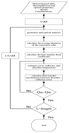
Figure 6.
CPC solar collector simulation algorithm.
The simulated system is shown in Figure 7.
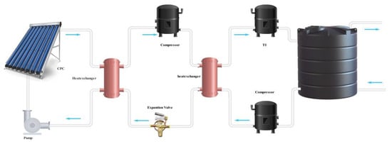
Figure 7.
Simulated system.
The installed CPC collector system with the high-temperature heat pump is shown in Figure 8.
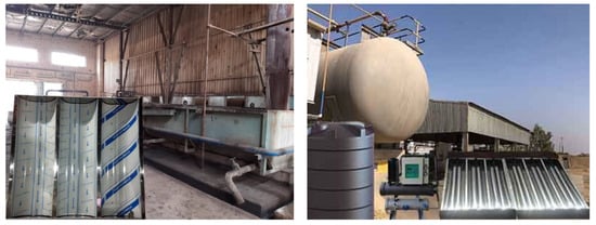
Figure 8.
CPC collector system with high-temperature heat pump.
First, it is necessary to enter the meteorological data of the equipment installation site and the optical and thermal properties of the solar collector materials. CPC solar collectors are divided into specific control volumes according to the length of their tube to evaluate the fluid temperature and thermal properties along the tube. Here, just to calculate the convective heat transfer coefficients of the fluid, the average pipe heat loss (hl) must be calculated. Before continuing the thermal analysis of the solar collector, it is necessary to estimate the collector coating temperature, the absorber temperature, and the reflector. When the useful fluid temperature is calculated by iteration and the coating temperatures of the solar collector, absorber tube, and parabolic reflectors are equal to the initial estimated temperature, the simulation software stops the temperature calculation iterations. The next volume control simulation considers the fluid outlet temperature as the inlet temperature. Mathematical models were simulated and coded in Span Hayes and MATLAB.
2.3. CPC Collectors Installed
Figure 9 shows the installation diagram of the CPC solar collector and high-temperature heat pump and the piping equipment and CPC solar collector temperature control instrument that comply with the standard [ASHRAE 2014] [77].
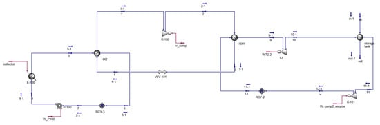
Figure 9.
Process status of the modeled system.
The CPC collector, which is installed as a hot water production system in a pipe manufacturing company, is shown in Figure 9. Installing CPC solar collectors in series or in parallel with the working fluid flow allows them to perform fluid circulation operations when the valves are opened or closed and to increase heat transfer. Additionally, to produce more hot fluid, several solar CPC collectors with specific capacities can be connected in series or in parallel.
3. Results and Discussion
In this study, the CPC solar collector system with oil working fluid with specific characteristics was used to transfer radiant energy heat. For one year, all experiments were performed daily, and the output temperatures were measured. The outlet temperatures of the tube are a function of the weather conditions and the amount of radiation. In the following, the amount of temperature and radiation is checked.
Environmental Conditions and Air Temperature
Due to the fact that Ahvaz is located in a hot and humid region and the temperature is warm in most months of the year, the high amount of air temperature and the temperature difference play important roles on the efficiency and power of the solar collectors. Solar collectors have different capacities on air temperature [58,78,79]. Table 2 shows the minimum and maximum air temperature of Ahvaz city. Figure 10 shows the daily changes in air temperature and Figure 11 shows the monthly changes.
Table 2.
Minimum and maximum air temperature in Celsius [80].
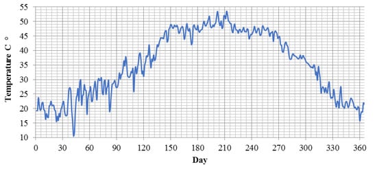
Figure 10.
Daily temperature in Ahvaz [80].
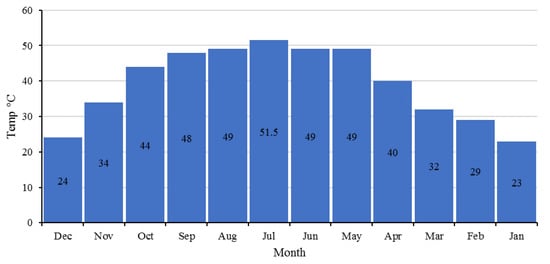
Figure 11.
Monthly temperature in Ahvaz [80].
The normal direct radiation on the ramp for all months of the year is shown separately in Table 3 and the daily radiation in Figure 11. The daily radiation is compared in Figure 12 and the outlet temperature from the collector in similar researches in different lengths of the absorber tube in Figure 13.
Table 3.
Normal direct radiation on the ramp for all months of the year separately.
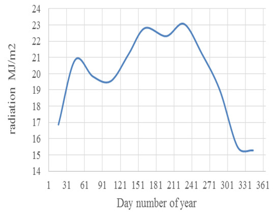
Figure 12.
Daily radiation MJ/m2.
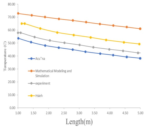
Figure 13.
Outlet temperature from the collector in similar research in different lengths of absorber tube.
The temperature of the fluid at the inlet point of the CPC collector adsorbent can be continuously measured with a thermometer. The results of the water outlet temperature at the adsorbent outlet point depend on the length of the CPC solar collector. In all diagrams, the temperature of the working fluid tends to increase, and this is related to the increase in the ambient temperature and solar energy that constantly appears on the receiver tube and is directly related to the length of the absorber tube. CPC solar collectors increase the inlet temperature of the working fluid by an average of 10 to 18 degrees depending on the calculated day number. This temperature is transferred to the heat pump after the heat and at the outlet of the heat pump. The temperature of the hot water increases and is transferred more than the temperature of the working fluid leaving the collector. In the characteristic curve of any CPC solar collector system, its efficiency curve allows the thermal efficiency to be measured based on the inlet temperature of the absorber tube, the ambient temperature at the collector installation site, and the solar radiation at the CPC solar collector installation site.
Figure 14 shows the effects of the absorber length and efficiency of CPC solar collector and the outlet temperature of the working fluid. According to the comparison and analysis of the results, the presented mathematical model is a logical result and in the experimental range of other researchers. Figure 15, Figure 16 and Figure 17 show the characterization results of a CPC solar collector operating at a flow rate. The simulation results of the CPC solar collector in MATLAB and Aspen HYSYS software were evaluated and compared with the experimental results and the results of other researchers.
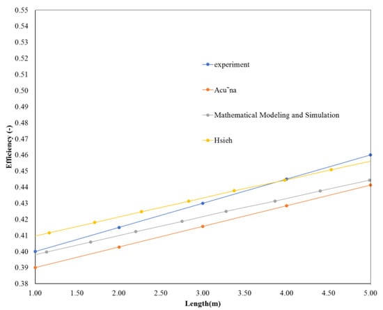
Figure 14.
The efficiency of the collector in different lengths of the absorber tube has been compared in similar researches.
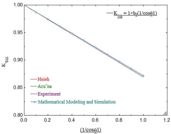
Figure 15.
Absorption coefficient of CPC solar collector efficiency.
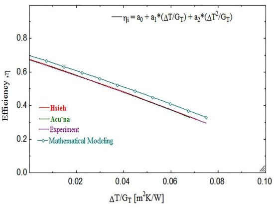
Figure 16.
The efficiency of the collector has been compared with the maximum ambient temperature and with similar researches.
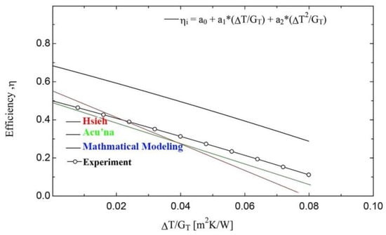
Figure 17.
The efficiency of the collector has been compared with the minimum ambient temperature and with similar researches.
4. Conclusions
In this paper, the mathematical heat transfer network modeling and CPC solar collector simulation with an absorber tube were performed and evaluated. This study was performed using a CPC solar collector and a mathematical model with a length of 2.81 m and a width of 0.32 m and an inside diameter of 0.01 m. This study was performed based on a CPC solar collector installed in a pipe company during one year. The proposed simulator showed a difference of 5 °C with other results. The comparison of the results of other studies showed that under the same parameters, shortened CPC solar collectors with an absorber tube achieve a 10% higher efficiency.
Author Contributions
All of the authors equally contributed to prepare this project. All authors have read and agreed to the published version of the manuscript.
Funding
The authors did not receive support from any organization for the submitted work.
Acknowledgments
The authors would like to thank Ahvaz Pipeline Company for technical support and assistance.
Conflicts of Interest
The authors declared no conflict of interest.
Nomenclature
| a | absorber |
| A | CPC area (m2) |
| amb | environment |
| Con | convective heat transfer |
| Cp | specific heat of the fluid (kJ °C−1 kg) |
| D | diameter (m) |
| ex | external |
| f | fluid |
| F | form factor |
| F0 | elimination coefficient (-) |
| fi | inlet fluid |
| fo | effluent |
| g | coverage |
| G | solar radiation (W m2) |
| h | heat transfer coefficient (W m2 K−1) |
| h0 | CPC height (m) |
| hf | coefficient of heat transfer coefficient of the fluid to the pipe wall (W m K−1) |
| i | internal |
| k | conductive heat transfer coefficient (W m K−1) |
| L | CPC length (m) |
| m | mass flow (kg s−1) |
| n | number of reflections |
| O | optical |
| o | outlet |
| P | pressure (bar) |
| Pr | Prandtl number |
| r | absorber radius (m); |
| r | reflector |
| Rad | radiation |
| Re | Reynolds number |
| S | absorbed radiation per unit area (W m−2) |
| sk | sky |
| T | temperature (°C) |
| Ul | total heat transfer coefficient (W m2 K−1) |
| Ula | total heat transfer coefficient in the fluid (W m2 K−1) |
| W | CPC width (m) |
| x0 | “x” point coordinate axis of CPC geometry |
| y0 | “y” point coordinate axis of CPC geometry |
| α | CPC absorption coefficient |
| γ | interception factor |
| ε | cover release |
| η | optical efficiency |
| θ | wide angle |
| ρ | reflection |
| σ | Stephen Boltzmann constant |
| τ | transfer |
| ϕ | angle to determine |
References
- Winston, R.; Hinterberger, H. Principles of cylindrical concentrators for solar energy. Sol. Energy 1975, 17, 255–258. [Google Scholar] [CrossRef]
- Ghalandari, M.; Maleki, A.; Haghighi, A.; Shadloo, M.S.; Nazari, M.A.; Tlili, I. Applications of nanofluids containing carbon nanotubes in solar energy systems: A review. J. Mol. Liq. 2020, 313, 113476. [Google Scholar] [CrossRef]
- Rabl, A. Solar concentrators with maximal concentration for cylindrical absorbers. Appl. Opt. 1976, 15, 1871–1873. [Google Scholar] [CrossRef] [PubMed]
- Hsieh, C.K. Thermal analysis of CPC collectors. Sol. Energy 1981, 27, 19–29. [Google Scholar] [CrossRef]
- Tripanagnostopoulos, Y.; Yianoulis, P.; Papaefthimiou, S.; Zafeiratos, S. CPC Solar Collectors With Flat Bifacial Absorbers. Sol. Energy 2000, 69, 191–203. [Google Scholar] [CrossRef]
- Kim, Y.; Han, G.; Seo, T. An evaluation on thermal performance of CPC solar collector. Int. Commun. Heat Mass Transf. 2008, 35, 446–457. [Google Scholar] [CrossRef]
- Buttinger, F.; Beikircher, T.; Pröll, M.; Schölkopf, W. Development of a new flat stationary evacuated CPC-collector for process heat applications. Sol. Energy 2010, 84, 1166–1174. [Google Scholar] [CrossRef]
- Tíba, C.; Fraidenraich, N. Optical and thermal optimization of stationary non-evacuated CPC solar concentrator with fully illuminated wedge receivers. Renew. Energy 2011, 36, 2547–2553. [Google Scholar] [CrossRef]
- Lu, Z.S.; Wang, R.Z.; Xia, Z.Z.; Lu, X.R.; Yang, C.B.; Ma, Y.C.; Ma, G.B. Study of a novel solar adsorption cooling system and a solar absorption cooling system with new CPC collectors. Renew. Energy 2013, 50, 299–306. [Google Scholar] [CrossRef]
- Kessentini, H.; Bouden, C. Numerical and experimental study of an integrated solar collector with CPC reflectors. Renew. Energy 2013, 57, 577–586. [Google Scholar] [CrossRef]
- Gu, X.; Taylor, R.A.; Morrison, G.; Rosengarten, G. Theoretical analysis of a novel, portable, CPC-based solar thermal collector for methanol reforming. Appl. Energy 2014, 119, 467–475. [Google Scholar] [CrossRef]
- Li, G.; Pei, G.; Yang, M.; Ji, J.; Su, Y. Optical evaluation of a novel static incorporated compound parabolic concentrator with photovoltaic/thermal system and preliminary experiment. Energy Convers. Manag. 2014, 85, 204–211. [Google Scholar] [CrossRef]
- Goswami, D.Y. Principles of Solar Engineering; CRC Press: Boca Raton, FL, USA, 2015. [Google Scholar]
- Waghmare, S.A.; Gulhane, N.P. Flux concentration on tubular receiver of compound parabolic collector by surface areal irradiance method of ray tracing. Optik 2017, 136, 470–479. [Google Scholar] [CrossRef]
- Nashine, E.K.; Kishore, P. Thermal analysis of a compound parabolic collector. Int. J. Eng. Res. 2017, 6, 4–29. [Google Scholar]
- Shrivastava, R.L.; Vinod, K.; Untawale, S.P. Modeling and simulation of solar water heater: A TRNSYS perspective. Renew. Sustain. Energy Rev. 2017, 67, 126–143. [Google Scholar] [CrossRef]
- Li, Q.; Zheng, C.; Shirazi, A.; Bany Mousa, O.; Moscia, F.; Scott, J.A.; Taylor, R.A. Design and analysis of a medium-temperature, concentrated solar thermal collector for air-conditioning applications. Appl. Energy 2017, 190, 1159–1173. [Google Scholar] [CrossRef]
- Waghmare, S.A.; Chavan, K.V.; Muntode, P.B.; Gulhane, N.P. Experimentation of surface areal irradiance method for solar flux measurement in compound parabolic collector. Optik 2017, 147, 373–384. [Google Scholar] [CrossRef]
- Zheng, C.; Li, Q.; Rosengarten, G.; Hawkes, E.; Taylor, R.A. Compact, semi-passive beam steering prism array for solar concentrators. Appl. Opt. 2017, 56, 4158–4167. [Google Scholar] [CrossRef]
- Moradi, M.; Mehrpooya, M. Optimal design and economic analysis of a hybrid solid oxide fuel cell and parabolic solar dish collector, combined cooling, heating and power (CCHP) system used for a large commercial tower. Energy 2017, 130, 530–543. [Google Scholar] [CrossRef]
- Mehrpooya, M.; Tosang, E.; Dadak, A. Investigation of a combined cycle power plant coupled with a parabolic trough solar field and high temperature energy storage system. Energy Convers. Manag. 2018, 171, 1662–1674. [Google Scholar] [CrossRef]
- Pouyfaucon, A.B.; García-Rodríguez, L. Solar thermal-powered desalination: A viable solution for a potential market. Desalination 2018, 435, 60–69. [Google Scholar] [CrossRef]
- Expósito, A.J.; Monteagudo, J.M.; Durán, A.; San Martín, I.; González, L. Study of the intensification of solar photo-Fenton degradation of carbamazepine with ferrioxalate complexes and ultrasound. J. Hazard. Mater. 2018, 342, 597–605. [Google Scholar] [CrossRef] [PubMed]
- Maddigpu, P.R.; Sawant, B.; Wanjari, S.; Goel, M.D.; Vione, D.; Dhodapkar, R.S.; Rayalu, S. Carbon nanoparticles for solar disinfection of water. J. Hazard. Mater. 2018, 343, 157–165. [Google Scholar] [CrossRef] [PubMed]
- Widyolar, B.; Jiang, L.; Ferry, J.; Winston, R. Non-tracking East-West XCPC solar thermal collector for 200 celsius applications. Appl. Energy 2018, 216, 521–533. [Google Scholar] [CrossRef]
- Francesconi, M.; Antonelli, M. A CFD analysis to investigate thermal losses in a panel composed of several CPC concentrators. Therm. Sci. Eng. Prog. 2018, 5, 278–288. [Google Scholar] [CrossRef]
- Mahbubul, I.M.; Khan, M.M.A.; Ibrahim, N.I.; Ali, H.M.; Al-Sulaiman, F.A.; Saidur, R. Carbon nanotube nanofluid in enhancing the efficiency of evacuated tube solar collector. Renew. Energy 2018, 121, 36–44. [Google Scholar] [CrossRef]
- Hassanzadeh, A.; Jiang, L.; Winston, R. Coupled optical-thermal modeling, design and experimental testing of a novel medium-temperature solar thermal collector with pentagon absorber. Sol. Energy 2018, 173, 1248–1261. [Google Scholar] [CrossRef]
- Baranov, V. Device for Restricting in one plane the angular aperture of a pencil of rays from a light source. Russ. Certif. Authorship 1967, 79-112, 79–112. [Google Scholar]
- Pranesh, V.; Velraj, R.; Christopher, S.; Kumaresan, V. A 50 year review of basic and applied research in compound parabolic concentrating solar thermal collector for domestic and industrial applications. Sol. Energy 2019, 187, 293–340. [Google Scholar] [CrossRef]
- Smith, T.W.; Antman, E.M.; Friedman, P.L.; Blatt, C.M.; Marsh, J.D. Part III digitalis glycosides: Mechanisms and manifestations of toxicity. Prog. Cardiovasc. Dis. 1984, 27, 21–56. [Google Scholar] [CrossRef]
- Norton, B.; Kothdiwala, A.; Eames, P. Effect of inclination on the performance of CPC solar energy collectors. Renew. Energy 1994, 5, 357–367. [Google Scholar] [CrossRef]
- Kothdiwala, A.F.; Norton, B.; Eames, P. The effect of variation of angle of inclination on the performance of low-concentration-ratio compound parabolic concentrating solar collectors. Sol. Energy 1995, 55, 301–309. [Google Scholar] [CrossRef]
- Rönnelid, M.; Karlsson, B. Experimental investigation of heat losses from low-concentrating non-imaging concentrators. Sol. Energy 1996, 57, 93–109. [Google Scholar] [CrossRef]
- Fraidenraich, N.; De Lima, R.D.C.; Tiba, C.; Barbosa, E.d.S. Simulation model of a CPC collector with temperature-dependent heat loss coefficient. Sol. Energy 1999, 65, 99–110. [Google Scholar] [CrossRef]
- Riaz, H.; Ali, M.; Akhtar, J.; Muhammad, R.; Kaleem, M. Comparative Optical and Thermal Analysis of Compound Parabolic Solar Collector with Fixed and Variable Concentration Ratio. Eng. Proc. 2021, 12, 85. [Google Scholar]
- Masood, F.; Nallagownden, P.A.L.; Elamvazuthi, I.; Akhter, J.; Alam, M.A.; Yusuf, M. Design and Parametric Analysis of Compound Parabolic Concentrator for Photovoltaic Applications. In Proceedings of the 2020 8th International Conference on Intelligent and Advanced Systems (ICIAS), Kuching, Malaysia, 13–15 July 2021; pp. 1–6. [Google Scholar]
- Ortega, A.B.; Terán-Franco, A.; Castro, J.C.; del Río, J.A. Optical and thermal performance of a toroidal compound parabolic concentrator. Appl. Opt. 2021, 60, 2213–2221. [Google Scholar] [CrossRef]
- Li, Y.; Jiao, F.; Chen, F.; Zhang, Z. Design optimization and optical performance analysis on multi-sectioned compound parabolic concentrator with plane absorber. Renew. Energy 2021, 168, 913–926. [Google Scholar] [CrossRef]
- Shah, R.; Patel, J. Photovoltaic thermal technology with compound parabolic concentrator. Int. J. Ambient Energy 2022, 43, 1098–1102. [Google Scholar] [CrossRef]
- Chen, F.; Gui, Q. Construction and analysis of a compound parabolic concentrator to eliminate light escape in the interlayer of solar vacuum tube. Renew. Energy 2022, 191, 225–237. [Google Scholar] [CrossRef]
- Ortega, A.; Chandra, S.; McCormack, S.J. Design and Characterization of a Roof-Mounted Compound Parabolic Concentrator. In Sustainable Energy Development and Innovation: Selected Papers from the World Renewable Energy Congress (WREC) 2020; Sayigh, A., Ed.; Springer International Publishing: Cham, Switzerland, 2022; pp. 875–882. [Google Scholar] [CrossRef]
- Touré, S.; Sidibé, M. Design, Realization, and Preliminary Tests of a Three-Dimensional Compound Parabolic Concentrator (CPC) Solar Cooker in Abidjan (Côte d’Ivoire). In Sustainable Energy Development and Innovation: Selected Papers from the World Renewable Energy Congress (WREC) 2020; Sayigh, A., Ed.; Springer International Publishing: Cham, Switzerland, 2022; pp. 111–116. [Google Scholar] [CrossRef]
- Bhalla, V.; Khullar, V.; Parupudi, R.V. Design and thermal analysis of nanofluid-based compound parabolic concentrator. Renew. Energy 2022, 185, 348–362. [Google Scholar] [CrossRef]
- Timoumi, Y.; Tlili, I.; Nasrallah, S.B. Performance optimization of Stirling engines. Renew. Energy 2008, 33, 2134–2144. [Google Scholar] [CrossRef]
- Sarafraz, M.; Safaei, M.R.; Leon, A.S.; Tlili, I.; Alkanhal, T.A.; Tian, Z.; Goodarzi, M.; Arjomandi, M. Experimental investigation on thermal performance of a PV/T-PCM (photovoltaic/thermal) system cooling with a PCM and nanofluid. Energies 2019, 12, 2572. [Google Scholar] [CrossRef]
- Baum, H.P.; Gordon, J.M. Geometric characteristics of ideal nonimaging (CPC) solar collectors with cylindrical absorber. Sol. Energy 1984, 33, 455–458. [Google Scholar] [CrossRef]
- Carvalho, M.J.; Collares-Pereira, M.; Gordon, J.M.; Rabl, A. Truncation of CPC solar collectors and its effect on energy collection. Sol. Energy 1985, 35, 393–399. [Google Scholar] [CrossRef]
- Rabl, A. Optical and thermal properties of compound parabolic concentrators. Sol. Energy 1976, 18, 497–511. [Google Scholar] [CrossRef]
- Rabl, A. Comparison of solar concentrators. Sol. Energy 1976, 18, 93–111. [Google Scholar] [CrossRef]
- Ortega, N.; García-Valladares, O.; Best, R.; Gómez, V.H. Two-phase flow modelling of a solar concentrator applied as ammonia vapor generator in an absorption refrigerator. Renew. Energy 2008, 33, 2064–2076. [Google Scholar] [CrossRef]
- Ustaoglu, A.; Alptekin, M.; Okajima, J.; Maruyama, S. Evaluation of uniformity of solar illumination on the receiver of compound parabolic concentrator (CPC). Sol. Energy 2016, 132, 150–164. [Google Scholar] [CrossRef]
- Sheikholeslami, M.; Zareei, A.; Jafaryar, M.; Shafee, A.; Li, Z.; Smida, A.; Tlili, I. Heat transfer simulation during charging of nanoparticle enhanced PCM within a channel. Phys. A Stat. Mech. Appl. 2019, 525, 557–565. [Google Scholar] [CrossRef]
- Sarafraz, M.M.; Tian, Z.; Tlili, I.; Kazi, S.; Goodarzi, M. Thermal evaluation of a heat pipe working with n-pentane-acetone and n-pentane-methanol binary mixtures. J. Therm. Anal. Calorim. 2020, 139, 2435–2445. [Google Scholar] [CrossRef]
- Oommen, R.; Jayaraman, S. Development and performance analysis of compound parabolic solar concentrators with reduced gap losses-oversized reflector. Energy Convers. Manag. 2001, 42, 1379–1399. [Google Scholar] [CrossRef]
- Tlili, I.; Timoumi, Y.; Nasrallah, S.B. Analysis and design consideration of mean temperature differential Stirling engine for solar application. Renew. Energy 2008, 33, 1911–1921. [Google Scholar] [CrossRef]
- Hsieh, C.K.; Mei, F.M. Empirical equations for calculation of CPC collector loss coefficients. Sol. Energy 1983, 30, 487–489. [Google Scholar] [CrossRef]
- Duffie, J.A.; Beckman, W.A.; Blair, N. Solar Engineering of Thermal Processes, Photovoltaics and Wind; John Wiley & Sons: Hoboken, NJ, USA, 2020; pp. 250–300. [Google Scholar]
- Heidaryan, E.; Jarrahian, A. Natural gas viscosity estimation using density based models. Can. J. Chem. Eng. 2013, 91, 1183–1189. [Google Scholar] [CrossRef]
- Heidaryan, E.; Esmaeilzadeh, F.; Moghadasi, J. Natural gas viscosity estimation through corresponding states based models. Fluid Phase Equilibria 2013, 354, 80–88. [Google Scholar] [CrossRef]
- Tchinda, R.; Kaptouom, E.; Njomo, D. Heat and mass transfer processes in a solar still with an indirect evaporator–condenser. Energy Convers. Manag. 2000, 41, 93–107. [Google Scholar] [CrossRef]
- Jarrahian, A.; Karami, H.R.; Heidaryan, E. On the isobaric specific heat capacity of natural gas. Fluid Phase Equilibria 2014, 384, 16–24. [Google Scholar] [CrossRef]
- Klein, S.A.; Beckman, W.A.; Mitchell, J.W.; Duffie, J.A.; Duffie, N.A.; Freeman, T.L.; Mitchell, J.C.; Braun, J.E.; Evans, B.L.; Kummer, J.P.; et al. TRNSYS 16–A TRaNsient System Simulation Program, User Manual; Solar Energy Laboratory, University of Wisconsin-Madison: Madison, WI, USA, 2004. [Google Scholar]
- Tchinda, R. Thermal behaviour of solar air heater with compound parabolic concentrator. Energy Convers. Manag. 2008, 49, 529–540. [Google Scholar] [CrossRef]
- Tchinda, R.; Kaptouom, E.; Njomo, D. Study of the CPC collector thermal behaviour. Energy Convers. Manag. 1998, 39, 1395–1406. [Google Scholar] [CrossRef]
- Yeung, M.; Yuen, P.; Dunn, A.; Cornish, L. Performance of a solar-powered air conditioning system in Hong Kong. Sol. Energy 1992, 48, 309–319. [Google Scholar] [CrossRef]
- Tchinda, R.; Ngos, N. A theoretical evaluation of the thermal performance of CPC with flat one-sided absorber. Int. Commun. Heat Mass Transf. 2006, 33, 709–718. [Google Scholar] [CrossRef]
- Aghanajafi, C.; Dehghani, A. Advanced Solar Radiation Energy and Industrial Application; K.N.Toosi University of Technology: Tehran, Iran, 2008; Volume 1. [Google Scholar]
- Florschuetz, L.W. Extension of the Hottel-Whillier model to the analysis of combined photovoltaic/thermal flat plate collectors. Sol. Energy 1979, 22, 361–366. [Google Scholar] [CrossRef]
- Belu, R. Fundamentals and Source Characteristics of Renewable Energy Systems; CRC Press: Boca Raton, FL, USA, 2019. [Google Scholar]
- Kitching, T. Development of a Tracking Compound Parabolic Collector for a Solar-Driven Diffusion Absorption Cycle. Ph.D. Thesis, North-West University, Potchefstroom, South Africa, 2018. [Google Scholar]
- Harmim, A.; Merzouk, M.; Boukar, M.; Amar, M. Mathematical modeling of a box-type solar cooker employing an asymmetric compound parabolic concentrator. Sol. Energy 2012, 86, 1673–1682. [Google Scholar] [CrossRef]
- Zheng, W.; Yang, L.; Zhang, H.; You, S.; Zhu, C. Numerical and experimental investigation on a new type of compound parabolic concentrator solar collector. Energy Convers. Manag. 2016, 129, 11–22. [Google Scholar] [CrossRef]
- Salek, F.; Eshghi, H.; Zamen, M.; Ahmadi, M.H. Energy and exergy analysis of an atmospheric water generator integrated with the compound parabolic collector with storage tank in various climates. Energy Rep. 2022, 8, 2401–2412. [Google Scholar] [CrossRef]
- Heidaryan, E.; Salarabadi, A.; Moghadasi, J. A novel correlation approach for prediction of natural gas compressibility factor. J. Nat. Gas Chem. 2010, 19, 189–192. [Google Scholar] [CrossRef]
- Heidaryan, E.; Moghadasi, J.; Salarabadi, A. A new and reliable model for predicting methane viscosity at high pressures and high temperatures. J. Nat. Gas Chem. 2010, 19, 552–556. [Google Scholar] [CrossRef]
- Sarafraz, M.M.; Tlili, I.; Tian, Z.; Bakouri, M.; Safaei, M.R. Smart optimization of a thermosyphon heat pipe for an evacuated tube solar collector using response surface methodology (RSM). Phys. A Stat. Mech. Appl. 2019, 534, 122146. [Google Scholar] [CrossRef]
- Kalogirou, S.A. Solar Energy Engineering: Processes and Systems; Academic Press: Cambridge, MA, USA, 2014. [Google Scholar]
- Sheikholeslami, M.; Haq, R.-u.; Shafee, A.; Li, Z.; Elaraki, Y.G.; Tlili, I. Heat transfer simulation of heat storage unit with nanoparticles and fins through a heat exchanger. Int. J. Heat Mass Transf. 2019, 135, 470–478. [Google Scholar] [CrossRef]
- Ahvaz Municipality Official. Available online: https://www.ahvaz.ir/ (accessed on 14 December 2022).


Disclaimer/Publisher’s Note: The statements, opinions and data contained in all publications are solely those of the individual author(s) and contributor(s) and not of MDPI and/or the editor(s). MDPI and/or the editor(s) disclaim responsibility for any injury to people or property resulting from any ideas, methods, instructions or products referred to in the content. |
© 2022 by the authors. Licensee MDPI, Basel, Switzerland. This article is an open access article distributed under the terms and conditions of the Creative Commons Attribution (CC BY) license (https://creativecommons.org/licenses/by/4.0/).