Abstract
Unsteady pressure-pulsation-induced severe vibration and high alternating stress can cause some unexpected results, including impeller crack and structural damage of the entire pumping system. In the present paper, a review on pressure pulsations in pumps is carried out based on the published studies. A comprehensive view on pressure pulsations from several aspects is discussed in detail. The contents of the studies include the mechanism of rotor–stator interaction; a prediction model and experimental and numerical investigations of pressure pulsations; unsteady rotating-stall-induced pressure pulsations at off-design flow rates; the relationship between pressure pulsation and the internal flow structure and cavitation; and the reduction in pressure pulsation caused by some effective approaches. It is concluded that unsteady pressure pulsation in pumps is closely associated with complex flow structures, for instance flow separation, cavitation, and rotating stall. The rotor–stator interaction mainly dominates pressure pulsation characterized by the discrete components in pressure spectrum. To reduce pressure pulsation, some effective approaches are proposed, such as increasing the rotor–stator gap, staggered blade, and blade modification. Finally, several suggestions for future works are given and discussed considering the current research. The review contributes to better understanding of pressure pulsations in centrifugal pumps, and may also benefit engineers in controlling pressure pulsations in some fields, such as pumps in nuclear reactor.
1. Introduction
As important fluid machinery, pumps are widely used in both industry and daily life, but they also consume large amounts of electric power [1]. Taking China, for instance, Wang et al. estimated that power consumption by pumps accounts for almost 20% of the total generated electricity [2]. Therefore, pumps are a crucial consideration in building an energy-saving society, considering their significant energy consumption. Fu et al. note that to address the increasing demand for energy saving, the stability and long-term operation of the pump are very important in many fields [3]. For example, in power stations, if an unexpected shutdown of the main feed pump occurs, significant losses will result. This is more significant in the nuclear power plant, where the nuclear reactor coolant pump is required to run safely for almost 60 years without any repair of the main hydraulic components [4,5]. As for the safe operation of the pump, two main factors are discussed in this paper, namely the mechanical and fluid dynamic effects. The problem of unsteady fluid dynamics is attracting more attention. It is a phenomenon that leads to alternating forces acting on the impeller and the volute, threating pump safety [6,7,8]. Furthermore, compared with the mechanical factor, the phenomenon of unsteady fluid dynamics is complex and more difficult to predict and analyze. Therefore, it should be emphasized to guarantee the safe operation of the pump.
As a typical unsteady flow phenomenon, rotor–stator-interaction- (RSI) induced high pressure pulsation is detrimental to the stable operation of the pump [9]. A corresponding diagram can be seen in Figure 1. Rotor–stator interaction is considered the main cause of intense pressure pulsations in pumps, and is a focus of research. With the blade sweeping the tongue or diffuser, the flow shedding from the blade trailing edge interacts with the stator, and the corresponding non-uniform flow distribution is generated [10,11]. Such a phenomenon is characterized by intense fluctuations in pressure and velocity. On some occasions, if the resonant frequency of the structure coincides with the induced pressure frequency, severe vibration phenomenon is caused [12,13]. Moreover, the alternating stress on the impeller can lead to the blade cracking, and such a phenomenon is not rare, especially for the turbine runner. Affected by rotor–stator interaction, some discrete components are generated in the pressure spectrum. The blade passing frequency and its high harmonics dominate the pressure spectrum, a phenomenon closely associated with the combination of the blade and diffuser numbers [14]. Different blade and diffuser numbers determine the predominant component in the pressure spectrum. Of course, without the stator, pressure pulsation can also be generated due to non-uniform flow distribution at the blade outlet, but the intensity is much weaker. For the impeller–volute matched pump, pressure pulsation is characterized by the blade passing frequency, but for the impeller–diffuser matched pump, pressure pulsation is more complex. Although theoretical analysis is proposed to predict the dominant component caused by different rotor–stator matched numbers, the effect of rotor–stator matched number on pressure pulsation still needs to be clarified, especially through experiments.
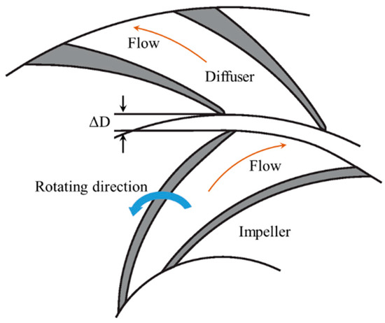
Figure 1.
Diagram of rotor–stator interaction between the rotating impeller and stationary diffuser.
Pressure pulsation energy is easily affected by the flow rate of the pump. Usually, due to the flow inlet angle changing, the uniformities of the internal flow distribution in the blade channels and the jet-wake flow pattern at the blade outlet deteriorate, leading to the pressure pulsation level increasing rapidly. Especially at low flow rates, flow separation and even rotating stall occur, and pressure pulsation signals are deeply affected [15,16].
Many studies have been carried out considering unsteady pressure pulsations in pumps, especially for rotor–stator interaction. Several topics have been investigated, including the mechanism of rotor–stator interaction, the relationship between pressure pulsation and flow structure, and the reduction of pressure pulsation. The numerical simulation method is often applied to discuss and predict pressure pulsation characteristics, and the RANS (Reynolds Averaged Navier–Stokes) method is commonly used [17]. Due to the inadequate ability of the RANS model to capture precise flow structures in pumps, researchers are using more advanced numerical methods, such as DDES (Delayed Detached Eddy Simulation) and LES (Large Eddy Simulation) to resolve the internal flow structures [18]. In earlier studies, the RANS model was used by most scholars from the comparison with the experimental data, and it was proven that the RANS could not adequately predict flow structures and pressure pulsations for pumps in off-design working conditions, and significant errors were caused. This is the reason that the more advanced numerical method was adopted in recent years. Figure 2 shows the typical wake flow pattern and the interaction with the diffuser in a reactor coolant pump using the LES method. Experiments based on the fast frequency response transducer are used to clarify pressure pulsations, which are more effective to predict the non-linear harmonics of the blade passing frequency [19]. The main purpose of pressure pulsation investigation is to establish an effective approach to controlling and reducing the pressure pulsation energy of the pump. To realize this purpose, the effects of design parameters and some special structures of the pump are discussed in this work.
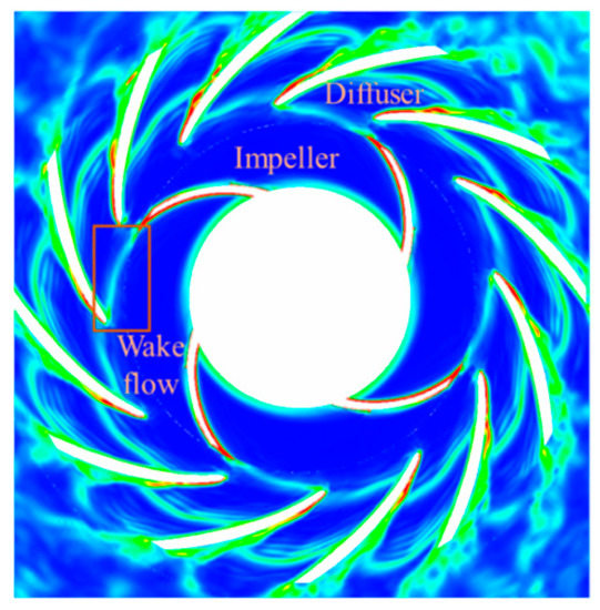
Figure 2.
Wake flow and the interaction with the diffuser by using LES method.
Pumps can usually be divided into two main types: the centrifugal pump (with and without diffusers) and the axial flow pump, as seen in Figure 3. The internal flow structures of the two types show significant differences. In the axial flow pump, due to the tip clearance existing between the impeller and the casing wall, leakage flow is likely to affect the unsteady flow characteristics of the pump, including the related hump phenomenon and even cavitation [20,21,22]. Recently, attention has been focused on leakage flow in the axial flow pump in attempts to clarify the interacting mechanism between the main flow and the leakage flow. For pressure pulsation, rotor–stator interaction is also the dominant factor in the axial pump, and is identical to that of the centrifugal pump. So, in the current paper, the review on the centrifugal pump is mainly conducted.
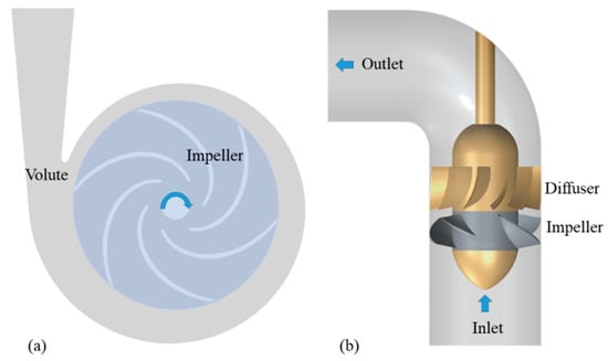
Figure 3.
Two general pump types. (a) The centrifugal pump with impeller–volute matched structure; (b) the axial flow pump with impeller–diffuser matched structure.
During the past decades, many studies have been carried out considering pressure pulsation in pumps, since high pressure pulsation has negative impacts on pump operation. Numerical and experimental methods have been combined to clarify the corresponding generating mechanism, pressure spectrum, and control method, etc. However, the published works are not well summarized. Therefore, in the present paper, pressure pulsations, mainly in centrifugal pumps, are reviewed, and the objective of this paper is to summarize the current research results with regard to pressure pulsations from several aspects. Moreover, the corresponding shortages are discussed to clarify the direction for future works. This paper is expected to provide a better understanding of pressure pulsations in pumps.
The related topics of the current paper are summarized as follows.
- Mechanism study of pressure pulsation, especially for rotor–stator interaction.
- Numerical simulation and experimental methods with regard to pressure pulsations to analyze pressure spectrum characteristics and investigate the factors affecting pressure pulsations.
- Typical rotating-stall-phenomenon-induced pressure pulsation at low flow rates, and its identification based on pressure signals.
- Relationship between pressure pulsation and the internal flow structure in the pump.
- Reduction of pressure pulsation energy in pumps by some effective approaches.
- Cavitation-induced pressure pulsation characteristics.
2. Mechanism Analysis on Unsteady Rotor–Stator Interaction
2.1. Rotor–Stator-Interaction-Induced Typical Frequencies
It is accepted that unsteady rotor–stator interaction is the predominant factor leading to high pressure pulsations in pumps, which has attracted the most attention in terms of theoretical, numerical, and experimental studies [23]. To explain the mechanism of rotor–stator interaction in a turbine airfoil, Dring et al. considered that two combined effects determined the interaction, namely the potential flow interaction and the wake interaction [24]. If the axial gap is lower than the airfoil chord, flow unsteadiness in both the upstream and downstream rows could be induced by the potential flow. Meanwhile, the downstream effect is caused by the wake flow with a gradual far-field decay rate. Based on this theory, Parker developed a quasi-steady solution for the potential flow interaction between two rows with relative motion [25,26]. It is concluded that high pressure pulsation is caused by the interacting rows with relative motion to the stationary rows. It means that the interaction effect leads to intense flow fluctuation.
To depict rotor–stator interaction with the impeller periodically sweeping the stator, an interacting mode was developed by Tanaka to analyze the vibration and dynamic stress behaviors in a high head reversible pump-turbine, which is widely used in the fluid machinery [27]. Figure 4 shows the diagram of interaction between the impeller and vanes of a pump-turbine at various impeller positions [28]. Some fundamental components and the harmonics are induced due to the rotor–stator interaction. The blade number of the rotor is ZB, and the number of the corresponding stationary stator is ZV. The excited frequencies could be calculated using the following equations.
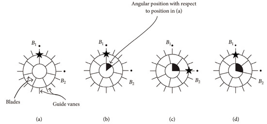
Figure 4.
Relative position of rotor with respect to the stator of a pump-turbine, (a–d) means different blade positions [27].
The resulting frequency exerted by the rotor on the stator is:
Likewise, the rotor experiences an alternating force from the stator with the frequency:
where nd is the rotational speed, and q and h are positive integers. Usually, and are regarded as the fundamental frequencies, and q and h are called harmonic numbers.
The relationship between Equations (1) and (2) could be described in Equation (3):
where N is the integer; it is also called the diameter mode.
Several combinations of q, h, and N could satisfy the equation, taking ZB = 7 and ZV = 16 for instance. A list is presented in Figure 5 [29]. It is observed that for q = 9 and h = 4, n = 1 is expected. It is usually considered that the most predominant component will occur at the low diameter mode. This means that high pressure amplitude will locate at the ninth harmonic of the blade passing frequency, namely 9ndZB, which is followed by the second and fifth, etc.
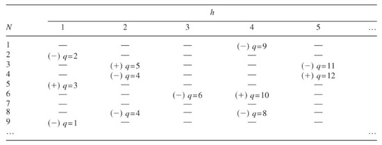
Figure 5.
Expected frequencies and diameter modes for the given combination of ZB = 7 and ZV = 16 [29].
For different diameter modes, the excited vibration patterns show significant differences. Figure 6 presents vibration modes (mode shape) at n = 1, 2, 3, and 4. The mode shape rotates with the rotor rotating direction in the stationary reference frame when N is a positive value, and it rotates against the rotor with the negative value [27]. During the design, it is really important to avoid the possible resonance between the rotor–stator-interaction-induced pressure excitation and the structural natural frequency. So the adopted blade numbers should be calculated carefully [30].
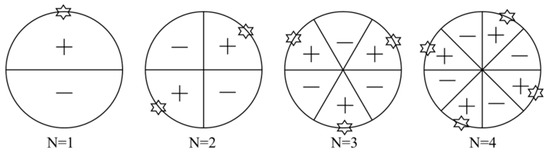
Figure 6.
Vibration patterns at different diameter modes (n = 1, 2, 3, 4) [27].
2.2. Theoretical Prediction of Rotor–Stator Interaction
By using a Fourier series to describe the periodic force caused by the rotor–stator interaction, a theoretical method was proposed by Rodriguez et al. [29]. The corresponding method took several effects into consideration, including the moving and stationary blade numbers, the non-uniform fluid force, and the sequence of interaction. Compared with the experimental results, it was observed that the method could predict the frequency and amplitude.
The periodic force could be calculated by Equation (4) [29].
Here, is the rotation speed rad/s, Fi,n is the force amplitude, i, n is the ith harmonic of at the nth blade, and is the phase.
Fn in the x-axis direction is given in Equation (5).
is the initial angular of the nth blade, and is the initial angular of the runner.
After some transforms by mathematical methods, the final excitation in the x-axis is shown in Equation (7).
Using the above functions, the excitation frequency and amplitude due to rotor–stator interaction could be predicted.
As for rotor–stator interaction in the centrifugal pump with impeller–volute matched type, the volute tongue could be regard as the stationary part with ZV = 1. In the general centrifugal pump, the blade passing frequency fBPF will dominate the pressure spectrum. To predict the amplitude at fBPF, the numerical simulation method could be used; however, it consumes more time. Parrondo et al. developed an acoustic method to predict the corresponding amplitude [31]. The parameters in the model were adjusted by the experimental data. However, it assumed that the pressure distribution on the periphery of the volute was uniform, which was not rigorous.
where c is the sound speed, and is the cross section area of the volute.
The above theoretical analysis is very useful for pump design. For the pump with vaned diffuser, by using the Formula (3), it is easy to obtain the dominant frequency for the typical impeller/diffuser match type, and the unsuggested blade match number should be avoided. It is always assumed that with the unsuggested match number, high pressure pulsation and even abnormal vibration will be caused. However, during the application, the unsuggested impeller/diffuser match number is often used by the researcher, for instance in one study, ZB = 4 and ZV = 12 were used, and no abnormal pressure pulsation was excited [30]. Therefore, how the match number affects pressure pulsation still needs to be clarified, especially by experiments.
3. Experimental Investigation of Pressure Pulsations
To investigate unsteady pulsations in pumps, experimental methods are very important, and should capture all the induced components in the pressure spectrum. Numerical simulation could not predict these precisely, especially the non-linear frequency. During pressure pulsation experiments, the fast frequency response transducer is the critical item of equipment. Emphasis is placed on the following several topics: pressure pulsation characteristics both for time domain signals and pressure spectra, influence of pump parameters on pressure pulsation, effect of flow rate on pressure pulsations, and reduction of pressure pulsations. Moreover, experimental results are also used to validate the CFD accuracy.
Early in 1982, Kojima et al. focused on pressure pulsations in an axial piston pump [32]. During the experiments, the semiconductor transducer was applied to extract unsteady pressure signals, and mean pressure was obtained by the oscilloscope and dynamic pressure. The results showed that discrete components were captured on the pressure spectrum, and the 10th harmonic frequency was obtained. The flow ripple of the pump system was caused by the low flow compressibility.
To comprehensively understand pressure pulsations in centrifugal pumps, Guelich et al. investigated 36 tests with different pump configurations to clarify the level and varying characteristics of pressure pulsations [33]. It was the first time that pressure pulsations in centrifugal pumps had been discussed in depth. During the study, some concepts and parameters were proposed to represent pressure pulsations, namely peak-to-peak value Δpp-p, amplitude Δpa = 1/2Δpp-p and RMS amplitude as seen in Equations (14) and (15). Moreover, the dimensionless treatment for pressure amplitude was also introduced in Equation (16). During the research, the effects of the rotating speed, Reynolds number, the system, and the gap between the impeller and diffuser on pressure pulsations were carried out. After a statistical study of the 36 tested pumps, a safety criterion was established to guarantee the safe operation of the pump considering the allowable pressure pulsation level.
As for pressure pulsations in pumps, pressure spectra are always dominated by the discrete components caused by the blade passing frequency and its harmonics. Moreover, non-linear frequencies with the form of are also induced due to the interaction between the blade passing frequency and the impeller rotating frequency, where a and b are integers. In order to manipulate pressure spectrum, Akin et al. designed an actively controlled flow pumping system to adjust the pressure spectral feature of wake and wake–blade interaction [34]. The special actively controlled system could manipulate perturbations of the inflow, the impeller, and the corresponding phase shift. It was found that discrete components in the pressure spectrum could be changed by the system. In proper selected perturbation conditions, pressure amplitude at the blade passing frequency and its high harmonics and the inflow perturbation could be attenuated significantly. It was the first time the pressure spectrum had been manipulated in the pump. Zhang et al. also captured the non-linear components generated by the interaction between the blade passing frequency and the impeller rotating frequency [35].
Due to the rapid rotation of the impeller, it is not easy to measure pressure pulsations in the impeller of the pump. Guo et al. designed a unique mechanical system to measure the pressure pulsations of the impeller matched with a diffuser [36]. Pressure transducers were mounted on the pressure and suction sides as well as the hub disk. It was noted that the fundamental blade passing frequency and its corresponding high harmonics were successfully captured in the pressure spectrum. For the measuring points at different positions, pressure amplitudes at the blade passing frequency for the points at the pressure side of the blade trailing edge were much larger compared with the other points, which increased rapidly in off-design working conditions, as presented in Figure 7. Moreover, it validated the finding that pressure distributions showed evident non-uniform characteristics at the peripheries of the volute and impeller.
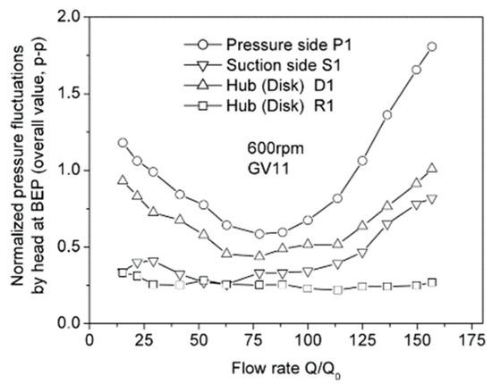
Figure 7.
Pressure amplitudes at different measuring points versus flow rate [36].
To investigate the influence of rotating speed on pressure pulsations, Khalifa et al. studied pressure pulsation at the blade passing frequency of a double volute pump [37]. Pressure signals at different flow rates and rotating speeds were obtained by the Omega DPX101-250 high response dynamic pressure transducers, which are located on the periphery of the volute casing and the discharge pipe. It was found that the blade passing frequency still dominated the pressure spectrum, even with the double volute. With the rotating speed increasing, for the concerned measuring points on the volute, pressure amplitudes rose rapidly, and the corresponding values were much larger than those at the discharge pipe. This indicates that it is not reasonable to identify the pressure pulsations of the pump using the point on the discharge pipe.
Parrondo et al. investigated the influence of operating point on the pressure pulsations of a centrifugal pump, and pressure signals at 36 different positions were extracted, from shut-off condition to 160% of the best efficiency condition [31]. It was observed that pressure pulsation level reached its minimum around the nominal flow rate, and in the shut-off condition, the increment was nearly 8 times that at the nominal flow rate. On the periphery of the volute, the angular distributions of pressure amplitudes at the blade passing frequency showed a modulated pattern, which were characterized by the alternating occurrence of the peak and valley caused by rotor–stator interaction. Based on the experimental data, a simple acoustic model to predict pressure amplitude was proposed, but it was not validated in other pumps.
Gao et al. investigated pressure pulsations of a low-specific-speed centrifugal pump in detail using the high-frequency response pressure transducers, as seen in Figure 8 [38]. To evaluate pressure pulsation energy in a particular frequency band, the RMS method was proposed, as seen the Equation (17), with An representing pressure amplitude at the typical frequency. The results showed that components with frequencies higher than 3fBPF could not be generated in the pressure spectrum for this pump type. For different measuring positions, the points at the tongue region were mostly affected by the flow rate, as seen in Figure 9. Moreover, the relationship between pressure pulsation and the internal flow structure was also discussed.
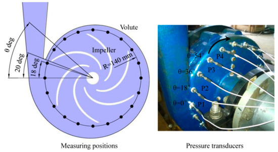
Figure 8.
Pressure transducers on the volute wall of the model pump [38].
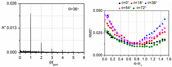
Figure 9.
Typical pressure spectrum for the centrifugal pump (left figure) and pressure pulsation energy versus flow rate at the points around the volute tongue (right figure) [38].
To investigate pressure pulsation characteristics in time-frequency domains, a spectral analysis was proposed by Pavesi et al. to clarify pressure instabilities of a centrifugal pump with vaned diffuser, including precursors and inception and evolution phenomena, as seen in Figure 10 [39]. It was observed that the generated non-linear components in pressure spectra experienced the appearing and disappearing processes in the time-domain with a regular interval. A fundamental component at the frequency of was captured for the point at the impeller discharge, which was probably caused by the pulsating wake zone at the corresponding position.
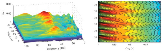
Figure 10.
Wavelet magnitude in the dynamo at the nominal flow rate of 600 r/min (left figure) and pressure evolution in the impeller mid height (right figure); DB means relative diffuser blade) [39].
The different relative positive positions of the diffuser with respect to the volute have a significant effect on pressure pulsations of the pump. Wang et al. focused on the influence of the corresponding effect [40]. The results proved that the relative positive effect not only affects the pump efficiency, but also pressure pulsations. When the blade trailing edge of the diffuser aligns with the left corner of the volute outlet, pressure pulsation energy is markedly attenuated. Thus, during the manufacturing, the relative position should be carefully selected to decrease the pressure pulsation level.
Experiments can effectively reveal pressure pulsations in pumps. However, experiments also have some limitations. For instance, most experiments use pressure transducers to measure pressure signals, which are placed on the volute casing. However, pressure signals within the blade channel are rarely measured and discussed due to the difficulty of measuring setup. From this point of view, the CFD is more convenient, and pressure signals at any position can be extracted to help us understand pressure pulsations in pumps. Moreover, for the experimental signals, the FFT method is often used to obtain the pressure spectrum, but it cannot obtain the time-frequency characteristics simultaneously. Correspondingly, others have advanced signal processing approaches; wavelet transform and short-time Fourier transform can be used, and more detailed information about pressure pulsations can be clarified.
4. Numerical Simulation of Pressure Pulsations
4.1. Numerical Simulation Based on URANS Method
With the computer performance increasing rapidly, numerical simulation method is an important approach to investigate pressure pulsations of pumps. The URANS (Unsteady Reynolds Averaged Navier–Stokes) method is widely used to predict pressure pulsation considering the low requirement of calculating resource. Many studies have been carried out based on the numerical simulation method to capture pressure pulsation signals, and also to clarify the relationship between geometrical parameters and internal flow structures.
To simulate pressure pulsations caused by the impeller–volute interaction of a centrifugal pump, González used the standard k-ε turbulent model to predict pressure signals, and measuring points were placed on the volute wall. It was validated that the k-ε turbulent model could successfully capture the blade passing frequency [41]. From comparison with the experimental data, it was observed that pressure amplitude at the blade passing frequency agreed well with experiments at some points under the nominal flow rate. However, the calculation error increased significantly for major points under off-design working conditions.
Barrio et al. investigated pressure pulsations and unsteady flow at the near tongue region of a centrifugal pump. The total mesh number 7.65 × 10⁵ was used, and a constant total pressure at the inlet section, and at the outlet section, a variable static pressure proportional to the exit kinetic energy was imposed at the boundary. Steady calculations were conducted using a frozen-rotor interface. A convergence criterion was established at a value of 10−5 for the scaled residuals. During the calculation, the k-ε turbulent model was applied with a time step of Δt = 1.6534 × 10⁻⁴ s [42]. Meanwhile, unsteady flow distributions with the blade sweeping the tongue were depicted. It was believed that by the currently used numerical approach, pressure pulsation due to rotor–stator interaction could be predicted; however, differences were observed in off-design working conditions, as seen in the position around φ = 20° in Figure 11. By combination analysis with the flow evolution, it was noted that the flow pulsation was associated with the jet-wake flow pattern and the secondary flow within the pump.
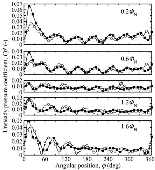
Figure 11.
Comparison of angular distributions between numerical and experimental results of pressure amplitudes at the blade passing frequency (Circles: numerical data; squares: experimental data) [42].
In centrifugal pumps, some fluid leaks from the impeller outlet region into the inlet suction pipe through the wear ring clearance. Due to the mixing and interacting effects of the leakage flow on the main flow, the uniform inlet flow condition at the impeller suction is affected significantly, and has an evident influence on the internal flow structure and also the pressure pulsation of the centrifugal pump. Thus, the corresponding effects induced by leakage flow have attracted researchers’ attention. Li et al. numerically investigated a centrifugal pump with the wear ring clearance based on the SST k-ω turbulent model [43]. It was observed that the leakage flow reached more than 6% of the total flow rate at the nominal flow rate, and it increased to about 9% at the low flow rate 0.2Qd. Pei et al. analyzed a single blade pump with the front chamber [44]. Based on SST k-ω turbulent model, Zhang et al. found that the asymmetric flow distribution was generated at the impeller suction region, which was affected by the leakage flow from the wear ring clearance at low flow rates. From comparison with experimental data, it was also observed that the calculation error increased rapidly when the flow rate deviated from the nominal working condition [35]. Alqarni et al. used the k-ε model to simulate the nanofluid flow through a 3D annulus [45].
By the numerical simulation method, it was possible for the researchers to clarify the effects of different geometrical parameters on pressure pulsations. Spence et al. used the standard k-ε turbulent model to investigate the effects of four parameters on the pressure pulsations of a double volute centrifugal pump, namely the vane arrangement, the cutwater gap, the sidewall clearance, and the snubber gap [46]. With different combinations, a total of 33 cases were discussed in detail to illustrate the resulted effects. It was demonstrated that the cutwater gap and vane arrangement were the strongest factors influencing pressure pulsations, while the other two parameters were considered less important. The obtained results were very useful in considering a pump design with low-pressure pulsation levels.
For the centrifugal pump with diffuser, the relative position of the diffuser with respect to the volute tongue affected the pump performance through a phenomenon namely known as the clocking effect. To capture the corresponding effect on pressure pulsations, Jiang et al. used the SST k-ω turbulent model to investigate the clocking effects at five different positions [47]. It was found that the clocking effect had little influence on the pressure pulsations in the diffuser. By contrast, pressure pulsations in the volute were affected significantly by the clocking effect. Finally, it was suggested that the volute tongue should be located around the middle position of the diffuser channel to obtain better pump performance.
4.2. Advanced Numerical Approaches towards Pressure Pulsations
As for the conventional RANS method, it cannot capture the complex flow structures with different scales due to its inherent physical limitations. To simulate pressure pulsations in pumps, one important goal is to establish an effective and precise approach. A mixed computational method, PANS, was proposed by Liu et al., considering both calculation precision and the needed resources [48]. Pressure pulsations around the “S” curve conditions of the pump-turbine were simulated. The results proved that the PANS method could predict the relative peak–peak amplitude successfully, and it agreed with the experimental data. Moreover, low frequencies in pressure spectrum could be captured due to the rotating stall phenomenon.
Recently, researchers have tried to use the more advanced numerical simulation methods, DES and LES, to predict unsteady pressure pulsations in pumps. Based on the DDES method, Zhang et al. numerically investigated the typical unsteady flow evolution of a low-specific-speed centrifugal pump, and the jet-wake flow pattern was depicted in detail [49].
Pacot et al. used the LES approach to simulate the unsteady pressure pulsation of a pump-turbine at pumping mode when the pump operated at off-design conditions [50]. It was validated that the LES method could capture the stall frequency, its propagation speed, and its flow field effectively, while the conventional URANS numerical method exhibited its intrinsic limit. Zhang et al. also applied the LES method to discuss pressure pulsations on the periphery of the volute in a centrifugal pump [51]. Li et al. compared the abilities of the LES and URANS approaches to predict pressure pulsations of a pump-turbine operating in pumping mode, and pressure pulsations were extracted at several positions. From the comparison, it was validated that with the identical mesh number, large eddy simulation could predict pressure pulsation better than the URANS approach, which overestimated the pressure pulsation level, as seen in Figure 12 [52].
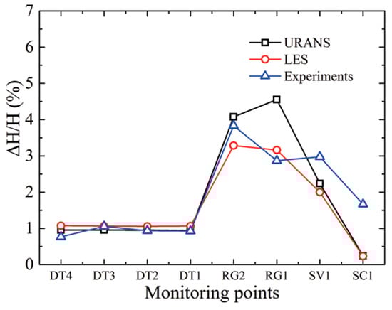
Figure 12.
Comparison of peak-to-peak amplitudes of pressure pulsation signals by URANS and LES methods [52].
For the pump with diffuser, the predominant component determined by the combination numbers of the impeller and diffuser occurs in the pressure spectrum, as discussed in the mechanism analysis, which does not always locate at the blade passing frequency, as proved by Wang et al. [40]. The author proved that for the impeller–diffuser matched pump, some dominant component will occur at the other frequencies, not always the blade passing frequency. However, this phenomenon is not easy to simulate and capture by the numerical simulation approach, even by LES method. Ni et al. compared in detail the pressure spectra produced by LES and experimental methods of an impeller—diffuser matched nuclear reactor coolant pump [53]. The blade number was four, and the diffuser number was twelve. From the theoretical analysis, it was concluded that the discrete peak at three times blade passing frequency, 3fBPF, dominated the pressure spectrum at the typical position, as discussed by Rodriguez [29], which is also proved by the experimental results [53]. However for the LES results, it was found that such a phenomenon could not be predicted, as seen in Figure 13, probably due to the mesh number and time step. As for the non-linear components in the pressure spectrum, no successful reports by CFD could be found in the pumps. Thus, it was concluded more work was required to improve the numerical simulation method to predict pressure pulsations precisely in pumps.
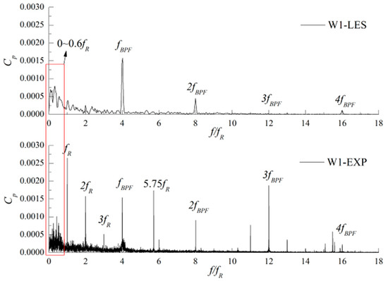
Figure 13.
Comparison of pressure spectra between LES and experimental data of a nuclear reactor coolant pump [53].
In the published works [48,49,50,51,52,53], it was concluded that the URANS model has an adequate ability to capture the dominant blade passing frequency of the pumps at the rated flow rate, while for the low frequencies in the frequency band, the URANS model was inadequate [42]. Moreover, when the pump operates at the part load conditions, the capacity of the URANS model seems to be limited, and evident error is caused by comparison with the experimental data, as validated by Gonzále et al. [41]. Thus, more advanced numerical methods are needed, such as LES and DDES, which will resolve the complex flow more precisely. However, the nonlinear components in pressure pulsations are not easy to capture in the pressure spectrum, even when using the LES and DDES methods [53], perhaps due to the limited temporal–spatial resolution. Thus, investigations are still needed to simulate pressure pulsation precisely.
5. Rotating-Stall-Induced Pressure Pulsations in Off-Design Conditions
For centrifugal pumps working at off-design conditions, the significant flow separation and the accompanied rotating stall phenomenon are generated within the pump at low flow rates. Especially for the pump with diffuser, unsteady rotating stall is often observed during pump operation, characterized by the “hump” shape in the head curve, as seen in Figure 14 [54]. As an intense unsteady flow phenomenon, the induced stall cell will propagate within the impeller or diffuser, causing significant pressure pulsation; moreover, the typical stall frequency also results when the frequency is lower than the impeller rotation frequency. Due to the great effect of the rotating stall on pressure pulsation, the safe operation of the pump or even the pumping system is markedly affected. Thus, the rotating-stall-induced pressure pulsation characteristic is emphasized to illustrate the generating mechanism and the related consequences.
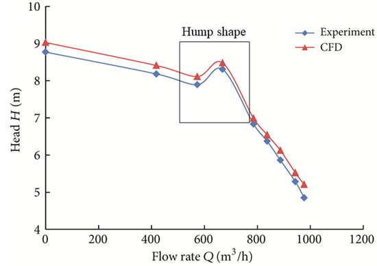
Figure 14.
Hump shape in the pump head indicating the rotating stall developing in the pump with diffuser [54].
5.1. Rotating Stall in the Pump with Impeller–Volute Matched Type
Ulum et al. experimentally investigated the rotating-stall-induced pressure pulsation characteristics within the impeller of a centrifugal pump, as seen the Figure 15 [55]. Two impellers with the blade numbers 6 and 7 were discussed. By pressure spectral analysis, it was observed that the stall frequency of 2 Hz could be detected in the pressure spectrum, which was about 5% of the impeller rotating frequency for the six-bladed impeller. When the pump operated at different flow rates, it was noted that the stall frequency had no direct relationship to the working condition. Moreover, it was noted that the blade number significantly affected the stall frequency within the impeller. Heng et al. studied the rotating stall in a radial flow pump with vaneless diffuser. During the experiments, the Brüel & Kjaer (Type 4135) pressure transducers were used to obtain unsteady pressure pulsation signals [56]. Moreover, the microphone was also applied. The results showed that the dominant stall modes at various working conditions were not identical, and three stall modes, characterized by four cells, two cells, and three cells, could be identified. Moreover, the rotating stall characteristics were identical when the impeller rotated at two different speeds.
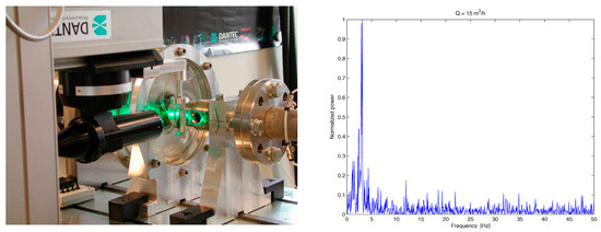
Figure 15.
Test platform to capture pressure pulsation signals in the rotating-stall condition (left figure) and the obtained spectrum in the stalled condition (right figure) [55].
Zhang et al. numerically investigated the rotating-stall phenomenon of a centrifugal pump with special slope volute based on standard k-ε turbulent model [57]. The low frequencies were generated in the pressure spectrum when the pump operated at very low flow rates. In the rotating stall condition, stall frequencies lower than 50% impeller rotating frequency could be identified. Meanwhile, it seemed that the stall frequency changed at different conditions for this special pump with the slope volute, and the stall cell was depicted by the relative velocity distribution within the blade channel. Zhao et al. also numerically studied the pressure pulsation characteristics of the rotating stall in a three-bladed pump at low flow rates [58]. To capture rotating-stall-induced pressure pulsation signals, several monitoring points were directly mounted within one blade channel. Pressure spectra were discussed in detail at various flow rates. Based on the streamlines of relative velocity, the stall cell was captured, and the corresponding evolution with the impeller rotating and propagation within the blade channel were also clarified.
The presence of volute and diffuser has a significant influence on the pressure pulsation and flow structure of the pump due to rotor–stator interaction. To exclude the influence of volute on rotating-stall-induced characteristics, Lucius et al. numerically investigated the rotating stall in a centrifugal pump with an outlet domain, rather than the conventional volute or diffuser. It was noted that the stall frequency at 7.3 Hz was detected in the spectrum, and it was about 70% of the impeller rotating frequency [59]. Moreover, it was suggested that in the blade channels, three stall cells were generated simultaneously, leading to high amplitude at the harmonic 21 Hz.
5.2. Rotating-Stall-Induced Pressure Pulsations in Pumps with Diffusers
As for rotating-stall-induced pressure pulsation in pumps with diffusers, some studies have been carried out. Sano et al. investigated the rotating stall in a pump with vaned diffuser. In the diffuser channel, flow instabilities, including rotating stall, asymmetric stall, and alternate stall, were obtained by the applied numerical approach [60]. It was found that the propagation speed and temporal wave form of the obtained pressure signals were affected by two rotating stall modes, namely the forward/backward rotating stall modes. The stall frequency at 0.24fn was captured in the pressure spectrum, and three cells existed at the same time. Using the large eddy simulation method, Pacot et al. predicted the rotating-stall phenomenon of a pump-turbine in pumping mode [61]. The obtained propagation speed of pressure pulsation and stall frequency showed high calculation precision compared with the experimental data. Figure 16 shows the pressure spectrum in the rotating stall condition. The propagation mechanism of the stall cell was clarified by the flow field distribution, which was determined by the growth and decay of the stall cell.
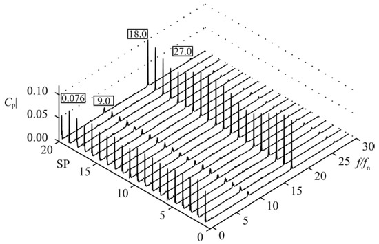
Figure 16.
Pressure spectra at inlet of the guide vane channel of the pump-turbine in pumping mode [61].
Using the CFD approach, the effects of rotating stall on pressure pulsation and internal flow structure of a pump-turbine at the pumping mode were also investigated by Xia et al. [62]. The results showed that high pressure pulsations were caused by the strong flow separation at mid-span of the guide when the pump operated in the rotating stall condition. To illustrate the typical flow distribution in the vane, the Q-criterion was applied to depict the inception and evolution of the rotating stall. It was noted that that the method could clarify the blocked effect of the stall cell on the vane channels as seen in Figure 17. Li et al. also used the CFD method to predict the evolution of the stall cell in a mixed flow pump, and the transfer of the stall cell in the blade channels caused intense pressure pulsation [54].
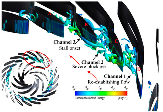
Figure 17.
Vortex distribution within the diffuser channels by Q-criterion [62].
Rotating-stall-induced pressure pulsation is not usually a focus for researchers studying pumps. Rotating stall always occurs at the low flow rates; especially for the centrifugal pump, the stall condition may be lower than 0.4Qd. The commonly used centrifugal pump will not operate at such low flow rates. Moreover, rotating stall is closely related to the blade number and blade exit angle. During the pump design, it is not difficult to select the appropriate parameters to avoid the rotating stall phenomenon. However, in some special conditions, for instance with the low-specific-speed pump with many blades and when working at low flow rates, rotating stall induces flow instability, and pressure pulsations should be concentrated due to its effect on the stable operating of the pumping system.
6. The Relationship between Pressure Pulsation and Internal Flow Structure
Rotor–stator-interaction-induced pressure pulsations are generated by the effect of the shed flow from the blade trailing edge striking the volute tongue or diffuser [63,64]. Even without the stator, pressure pulsation will also be excited due to the non-uniform flow distribution at the blade outlet. Therefore, the internal flow structure is the original source of pressure pulsations in pumps, and it determines the pressure pulsation level. The combination effects of pump parameters and operating conditions together affect the flow structure, which finally has a direct influence on pressure pulsations. For instance, at low flow rates, flow separation and reverse flow structure are generated at the impeller outlet region, leading to the pressure pulsation energy rising rapidly. The relationship between the internal flow structure and pressure pulsation is an important research topic regarding the pump. Many studies have been carried out to clarify and establish the corresponding relationship between flow structure and the resulting pressure pulsation.
Using particle displacement velocimetry to compute pressure field, Chu et al. discussed the relationship between pressure pulsation and unsteady flow in an impeller–volute matched centrifugal pump. The resulting noise characteristics were also determined [65]. It was found that pressure pulsations and far field noise were determined by the non-uniform flow shedding from the blade trailing edge and the subsequent impeller–volute interaction. Meanwhile, the total pressure was dominated by the vorticity distribution and the large vortex sheet resulting from the jet-wake flow pattern. The paper provides an in-depth understanding of the internal relationship between the flow and the pressure pulsation in the centrifugal pump.
Furthermore, Chu et al. depicted a detailed flow map with the blade passing the volute tongue to discuss the relationship between pressure pulsations and unsteady flow distributions [66]. It was validated that pressure pulsated significantly when the blade passed the volute tongue, and near the impeller, pressure reached its minimum when the blade aligned with the volute tongue. From the vorticity distribution, it was found that the vorticity sheet was generated around the interaction region, which was characterized by the high turbulence level. At the blade trailing edge, high turbulence could be formed, especially when the blade was located near the tongue. Usually, intense turbulence indicated high pressure pulsation energy, so the pressure pulsation was closely associated with the corresponding flow distribution.
To discuss the relationship between flow distribution and pressure pulsation, Choi et al. used hot-wire probes and pressure transducers mounted on the blade surface in a centrifugal pump without volute to obtain velocity and pressure distributions simultaneously [67]. The results showed that unsteady passage flow was caused by the high flow on the blade pressure side moving to the low-pressure region on the suction side. Due to the moving effect, the roll-up flow phenomenon developed around the blade trailing edge. Finally, the periodic pressure pulsation on the blade surface was caused by the unstable passage flow.
From the above analysis, it is concluded that pressure pulsation in the pump is closely related to the flow distribution at the blade outlet region and its subsequent interaction with the tongue. With the development of CFD, the corresponding flow distributions could be resolved and captured effectively to discuss the internal relationship between the flow field and pressure pulsation.
Based on the CFD approach, Barrio et al. numerically investigated unsteady flow distribution and its pulsation at the near-tongue area of the centrifugal pump at various flow rates [42]. It was found that flow fluctuation was related to the relative position of the blade with respect to the tongue due to the secondary flow and jet-wake flow structure in the blade channel. Pressure distribution was affected significantly by the flow separation, and it reached its maximum when the stagnation point aligned with the reference position. A similar study was found in the work of Kadambi et al. [68]. Posa et al. also studied the flow distributions and pressure pulsations of a centrifugal pump with different setting angles versus flow rate [69].
Recently, LES and DDES methods have been applied by researchers to clarify the relationship between the flow distribution and pressure pulsation. Just as discussed, the wake flow and its interacting effect determined the pressure pulsation. Thus, more attention has been focused on the wake flow shedding from the blade trailing edge and its striking process in consequence.
Drawing on the LES coupled with the immersed boundary method, Posa et al. numerically investigated the instantaneous flow distribution and its evolution process in a centrifugal pump with diffuser [70]. During the research, the immersed boundary method was used, and a total mesh number of 28 million was adopted to generate the entire computational domain of the mixed flow pump. Moreover, different SGS models were used to predict flow structures to clarify the calculation precision. As for boundary condition, the author prescribed a uniform velocity at the inflow plane and used convective condition at the outflow. From the results, it was observed that several significant vorticity sheets were generated within the model pump, especially at the blade suction side, where a high vorticity sheet was developed. Moreover, the unsteady evolution of the wake flow was revealed, and it was found that the vortical structures formed on the blade consequently shed in the wake with strong interaction with the blade suction side of the diffuser, as seen in Figure 18. It was the first study focusing on and clarifying the detailed unsteady wake flow in this particular pump. Some further studies on the pump have been carried out considering the effects of pump parameters and operating conditions [71]. Kye et al. also investigated the typical wake flow distribution and evolution using the LES method with a large mesh gird [72].
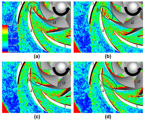
Figure 18.
Instantaneous vorticity distributions with the impeller sweeping the diffuser at four time points, (a–d) means different blade positions with respect to the diffuser [70].
Ni et al. also used the LES method to discuss the pressure pulsation and unsteady flow structure of a nuclear reactor coolant pump [73]. Pressure spectrum and wake flow evolution were discussed in detail. The results showed that vortices with positive and negative vorticity magnitudes shed alternately from the diffuser trailing edge, which was similar to the Karmen vortex street. In the pressure spectrum, it was observed that some components were induced by the shedding vortex. Moreover, the unsteady moving process of the wake flow from the impeller through the diffuser channel was depicted, and determined the blade passing frequency. Zhang et al. applied the LES method to simulate the complex flow and pressure pulsation in a low-specific-speed centrifugal pump [51]. The interactions of the vorticity sheets with the volute tongue were illustrated at various flow rates. For the measuring point located in the region with high vorticity magnitude, high-pressure amplitude at the blade passing frequency was generated. This indicated that pressure pulsations in pumps were closely associated with the corresponding vortical distribution. The conclusion was also validated by the authors using the DDES method with more mesh grid [49].
With the non-intrusive measuring technique developing, particle image velocimetry technique (PIV) could be used to capture the complex flow structures within the pump and reveal the intrinsic relationship of the flow-induced pressure pulsations, as seen in Figure 19. Using the PIV technique, unsteady flow structure and its evolution in a centrifugal pump operating at high-flow rate were investigated by Keller et al. [74]. The velocity, vorticity distribution, and turbulent kinetic energy were analyzed together, and attention was laid on the region around the volute tongue with intense rotor–stator interaction. From the evolution of the vorticity sheet with the impeller passing the volute tongue, it was evident that rotor–stator interaction was determined and dominated by the vorticity sheets shedding from the blade trailing edge and its consequent impingement with the volute tongue tip. Further and comprehensive analysis was carried out by Zhang et al., and evolutions of wake flows at different flow rates were clarified [75]. It was found that three interacting modes existed in the centrifugal pump at various flow rates. The obtained experimental results meant that the pressure pulsation level in the pump was closely associated with the wake flow at the blade trailing edge. Thus, by controlling the wake flow, pressure pulsation energy could be reduced significantly, which would be very useful considering the for low levels of pressure pulsation.
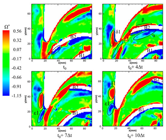
Figure 19.
Vorticity distributions at different impeller positions with respect to the volute tongue at 1.4Qd [75].
It is well accepted that pressure pulsations were associated with the flow distribution at the blade outlet, and the non-uniform flow field will lead to high pressure pulsations. From the recent studies using the advanced numerical approach with numerous mesh grid and optical measurement, it was validated that vortical structures are complex at the blade outlet, and the evident wake flow and the resulting interaction are generated around the RSI region. It is also inferred that by increasing the flow uniformity and controlling the wake flow at the blade outlet, pressure pulsations will be alleviated. This assumption is proven by recent works as discussed in the next section. The obtained results contribute to a thorough understanding of flow field and its relationship with pressure pulsations in centrifugal pumps.
7. Effective Approaches to Reducing Pressure Pulsations in Pumps
The most important research purpose with regard to pressure pulsations in pumps is to find an effective way to control and lower pressure pulsation energy. High-pressure pulsation characterized by the discrete components in the pressure spectrum will threaten the safe operation of the pump [76,77]. For the pumps applied in the typical fields including nuclear power stations, power stations, and the petrochemical industry, etc., the requirements of pressure pulsation are becoming pretty strict. In pumps, high pressure pulsation generates abnormal vibrations in some conditions, and has a negative effect on the pump’s operation. Moreover, in extreme cases, the alternative forces caused by the unsteady pressure pulsation leading to the cracking of the blade, especially at the blade’s trailing edge, as discussed by Doshi et al. [78]. Therefore, how to control pressure pulsation energy during the pump design is a critical factor that should be seriously considered by the designer. Some effective approaches have been carried out by researchers.
7.1. Influence of Geometrical Parameters
The blade number is an important parameter influencing pump performance and pressure pulsation. Yang et al. investigated the effect of the blade number on the pressure pulsations of a pump turbine in pumping mode [79]. It was observed that by increasing the blade number, pressure pulsation energy could be reduced evidently. The uniformity of flow distribution at the blade exit could be improved by increasing the blade number, resulting in the reduction in pressure pulsation level. The authors also discussed the effect of the wrap angle on the pump performance [80].
Tao et al. investigated the effect of the blade thickness on the pressure pulsations of a slurry pump [81]. When the blade thickness increased, pressure pulsation energy at the near-tongue region was reduced; however, opposite and varying trends were observed for the points at the far region from the volute tongue. Spence et al. discussed the effects of several parameters on pressure pulsations in a centrifugal pump. It was validated that the gap between the impeller and the volute mostly affected pressure pulsation level [46]. The blade outlet angle determined the direction of the discharge flow from the impeller and also the subsequent interaction with the volute tongue. Yang et al. analyzed the corresponding effects of several blade outlet angles on pressure pulsations [82]. The results showed that the amplitude at the blade passing frequency was reduced when the blade outlet angle increased. However, a negative effect was generated on the second-order blade passing frequency.
7.2. The Gap between the Rotor and the Stator
The rotor–stator interaction is determined by the wake flow shedding from the blade trailing edge and its impingement with the volute tongue [83,84,85]. Due to the gap between the rotor and the stator, the intensity of wake flow will be alleviated when it moves through the gap. Finally, increasing the gap is an effective and simple approach to reducing the pressure pulsation level. However, due to the flow dissipation, a negative influence on the pump performance will be generated if the gap is too large. Many studies have been carried out considering the impact of the gap. Al-Qutub experimentally investigated the effect of the gap on pressure pulsations in a double volute centrifugal pump. The gap ratio compared with the impeller diameter increased from 1.4% to 5% [86]. The obtained results are shown in Figure 20. It is evident that by increasing the gap, pressure amplitude could be reduced for all the concerned flow rates, especially in off-design working conditions. At the nominal flow rate, the decrement was about 35% at the 5% gap compared with the smallest gap of 1.4%.
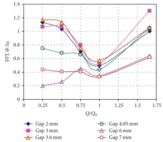
Figure 20.
Pressure pulsation magnitudes at different gaps when the pump works at various flow rates [86].
Yang et al. analyzed the influence of the gap on pressure pulsations. The gap ratio compared with the impeller diameter increased from 6.7% to 22.4% [87]. From the comparison of pressure amplitudes at the blade passing frequency, it was found that about a 50% reduction could be obtained by increasing the gap. Similar results were also reported by Solis et al. using the CFD approach [88]. Zhang et al. found that with the gap ratio lower than 20%, pressure pulsation energy reduced rapidly [57]. When the gap ratio was larger than 20%, pressure pulsation level decreased slowly with the gap increasing in a pump with special slope volute. This suggests that a reasonable gap ratio range exists considering the reduction in pressure pulsation energy. As recommended by Gülich, the gap ratio should be controlled at lower than 10% for the conventional centrifugal pump. The effect is not significant when the gap ratio exceeds 10%; moreover, the pump performance deteriorates with a large gap [89].
7.3. Modification of the Impeller
As the original source of rotor–stator interaction, the impeller plays an important role in rotor–stator-interaction-induced pressure pulsations. Modifications of the impeller have been investigated to reduce pressure pulsation energy.
The profile of the blade trailing edge significantly affects the wake flow. As for the hydrofoil, it has been validated that for the proper designed trailing edge shape, the intensity of the vortex shedding from the trailing edge and the corresponding induced vibration will be reduced [90,91]. In the hydraulic turbine, the effect of different blade trailing edge shapes on flow-induced pressure pulsation and vibration has been comprehensively investigated, and positive results obtained [92]. It is inferred that such modification will also have a positive effect on reducing pressure pulsation in the pump. Some investigations in this regard have been carried out. Gao et al. discussed the effect of the blade trailing edge profile on pressure pulsations in a low-specific-speed centrifugal pump [93]. Five different blade trailing edge profiles were compared. Using the numerical simulation method, it was shown that the proper designed blade trailing edge profile could significantly decrease pressure pulsation energy at the blade passing frequency. A decrement about of 7% could be obtained, as seen in Figure 21.
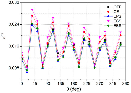
Figure 21.
Comparison of pressure amplitudes at the blade passing frequency when the pump works at the nominal flow rate [93].
Furthermore, the obtained conclusion was validated by the authors from experiments using the high-frequency response pressure transducers [94]. Based on the numerical results, the best profile of EPS was selected for experiment. It was observed that for all the concerned flow rates, the EPS profile could reduce the pressure pulsation energy. Moreover, the complex flow distributions at the blade outlet region were also analyzed to clarify the reduction mechanism from the internal flow aspect. Results showed that more uniform flow distribution and low turbulent intensity accounted for the reduction.
Al-Qutub et al. used experiments to explore the influence of the V-shaped cut of the impeller trailing edge on pressure pulsations in a centrifugal pump [95]. The results showed that the V-cut could reduce the pressure amplitude for all flow rates, a phenomenon caused by the increase in the gap between the impeller and the volute. Moreover, the authors also investigated some other cut types, including the S-cut and C-cut [96]. Wu et al. analyzed the influence of modifying the blade trailing edge on the performance of a mixed flow pump [97], proving that the reasonable blade trailing edge improved the pump performance. Moreover, the uniformity of flow distribution at the blade outlet region could be improved, which is beneficial for reducing the pressure pulsation level. For the modification of the diffuser trailing edge, Ni et al. investigated several modifications of the diffuser trailing edge in a nuclear reactor coolant pump, and the positive effect on lowering the pressure pulsation level could be obtained [73].
7.4. Special Designed Impeller and Volute
To reduce pressure pulsation energy, the special designed impeller and volute are investigated. For the impeller, the splitter blades are often used, which improve uniformity of flow at the impeller outlet region. Finally, the resulting pressure pulsation will be affected. Kergourlay et al. discussed the pressure pulsation and flow field affected by the splitter blades in a centrifugal pump [98]. It was noted that by using the splitter blades to the impeller, the velocity and pressure distributions on the periphery of the impeller became more homogeneous. Pressure signals were captured by the dynamic pressure transducers. From comparison with the original impeller, it was validated that adding the splitters could markedly reduce pressure pulsation. The corresponding effect was also discussed by GöLcü et al. [99], Li et al. [100], and Solis et al. [82], and the identical conclusion could be obtained.
Recently Chen et al. discussed the effect of the twisted inlet vice blade on the pump performance and pressure pulsation. It is believed that the special designed impeller has an effective influence on improving the pump performance [101]. With the objective of controlling the rotor–stator interaction in the centrifugal pump, a special slope volute was proposed by Zhang et al. [102]. The volute tongue did not face the impeller, thus the flow discharged from the impeller did not strike the tongue directly and intensely, leading to low-pressure pulsation. By experimental comparison, the special slope volute was shown to have a positive effect on decreasing the pressure pulsation energy of the pump, as seen in Figure 22. Meanwhile, the pump performance deteriorated with the use of the special slope volute, but this was not significant at the nominal and low flow rates.
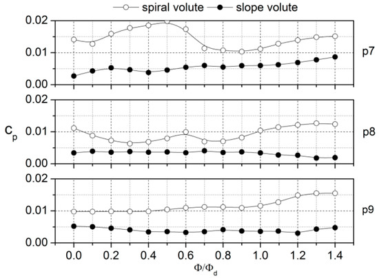
Figure 22.
Comparison of pressure amplitudes at the blade passing frequency between the conventional spiral volute and the slope volute with the same impeller [102].
As for the reduction of pressure pulsations, many methods are proposed, but some approaches may be limited and not universal [103]. For instance, by changing the geometrical parameters, the effect may be related to the special pump model. The most effective approach to reduce pressure pulsations for any pump is to increase the gap between the impeller and the stator, which has been validated by many studies. It is also a very convenient method for the pump designer, having little effect on the pump performance when the gap is not too large. Moreover, the large RSI gap also has a positive effect on reducing radial force on the impeller, and benefits the shaft stability. Thus, if the centrifugal pump vibrates intensively, cutting the impeller outlet is a powerful approach to generating lower-flow-induced vibration if the pump performance can be guaranteed after the trimming of the impeller.
8. Cavitation-Induced Pressure Pulsations
Cavitation, the important unsteady flow phenomenon in fluid machinery, has a negative effect on the performance, including on the head, efficiency, cavitation damage, vibration, and noise [104,105]. With a single cavitation bubble, during its collapse, a significant high-frequency signal will be emitted. With the occurrence of cavitation around the hydrofoil and in the fluid machinery, cloud cavitation, sheet cavitation, and vortex cavitation, etc. may be generated. Many studies have been carried out on the relationship between unsteady cavitation and induced pressure pulsations. Ji et al. proved that for complex cavitation around the hydrofoil, the cavity volume acceleration is the main source of the pressure fluctuations around the cavitating hydrofoil as seen in Figure 23 [106]. Moreover, the effect of different cavitation stages on pressure pulsations has also been discussed [107,108,109].
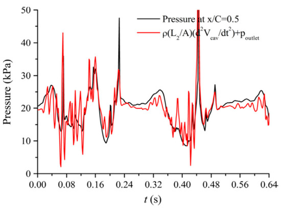
Figure 23.
Relationship between the cavity volume and induced pressure pulsations [106].
As for cavitation in pumps, Jens Friedrichs investigated the relationship between cavitation and pressure pulsations. The optical measurements of cavitation structures and pressure pulsating signals were acquired. The results showed that when the rotating cavitation occurred in the centrifugal impeller, a very low frequency was excited, much lower than the shaft rotating frequency [110]. Xu et al. discussed the effect of cavitation on pressure pulsation in a mixed-flow pump with vaned diffuser. It validated that with the occurrence of cavitation, the dominant frequency of pressure pulsation changed. Moreover, by increasing the tip clearance, cavitation will deteriorate significantly [111]. Sun et al. investigated the cavitation–vortex-pressure pulsation interaction in a centrifugal pump based on the numerical simulation method, and the results showed that pressure pulsations were associated with the cavitation instability, especially at the cavity rear [112]. Zhang et al. used the pressure transducers to measure the pressure signals of a low-specific-speed centrifugal pump, and the relationship between the cavitation stage and pressure pulsation energy was revealed [113]. The results showed that cavitation affected pressure pulsation at the blade passing frequency even before the critical point, and it fluctuated and then dropped rapidly around the critical point. The obtained results were similar to those involving cavitation-induced noise and vibration, as validated by Rus et al. in Figure 24 [114]. From this perspective, pressure signals can also be used to detect cavitation status in pumps.
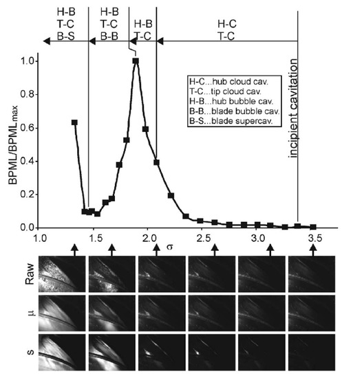
Figure 24.
Cavitation stage versus the induced hydrophone signals [114].
9. Conclusions and Future Works
9.1. Conclusions
Unsteady pressure pulsations play an important role in the stable operation of pumps. In the present paper, a literature review on pressure pulsations in pumps was carried out from several topics. Some conclusions are summarized here.
In this review paper, pressure-pulsation-generating mechanism, numerical and experimental investigation, cavitation-induced pressure pulsations, and reduction of pressure pulsations, etc., were discussed.
Pressure pulsations are related to the flow distribution within the pump and the rotor–stator interaction. The internal flow structures, including flow separation, rotating stall, and cavitation, affect pressure pulsations, which also means that the pump’s working condition determines the pressure pulsations. Numerical methods and experiments are often combined to investigate pressure pulsations in pumps, and the advanced DES and LES methods are used by many researchers to clarify flow field and pressure pulsations, considering the precision of these methods compared with URANS.
Considering the need for low-pressure pulsation to guarantee the stable operation of the pump, some effective approaches could be used to reduce pressure pulsation energy, which could be applied during the pump design to avoid unexpected damage caused by high-pressure pulsation, especially the method using the large RSI gap.
Pressure pulsations in centrifugal pumps are the focus of much research in this field, and many works have been carried out. In this paper, the issue pressure pulsations were reviewed from several aspects. Especially with regard to the reduction of pressure pulsation, although many works have been undertaken, a comprehensive review has been lacking. In this paper, the existing effective methods are summarized. It is believed that the paper will contribute to a better understanding of pressure pulsations in pumps, and will be beneficial for the reader and pump designer in this field.
9.2. Future Works
As for pressure pulsations in pumps, though many studies have been carried out, some in-depth future works are still needed to give a comprehensive understanding of pressure pulsations.
A satisfactory theory regarding rotor–stator interaction taking the working condition and geometrical parameters into consideration is still lacking. Using the theoretical method, we still cannot currently predict the pressure pulsation during pump design.
By high-frequency response pressure transducers, many experiments have been carried out to extract pressure signals on the volute wall or diffuser channel. However, experiments on pressure pulsations in the impeller are rarely conducted due to the impeller’s rotation, and few results could be found. Thus, studies on pressure pulsations within the impeller need to be facilitated by the design of a reasonable measuring system.
CFD is an important and useful technique for revealing pressure pulsation characteristics in pumps. For the general impeller–volute matched pump, pressure pulsations can be predicted effectively by the RANS, DDES, or LES methods. However, for the non-linear components and high harmonics of the blade passing frequency in the impeller–diffuser matched pump, the current CFD method lacks the adequate ability. Thus, predicting it precisely is still a problem that should be solved.
The relationship between the geometrical parameter and pressure pulsation is not established. This leads to difficulty for the pump designer in designing a pump with low-pressure pulsation. The corresponding relationship needs to be revealed in order to establish low-pressure pulsation design criteria, which will be very useful for designing pumps with low-pressure pulsation.
Author Contributions
N.Z. wrote the paper. D.L. collected the materials. B.G. gave the suggestions in the writing the paper. D.N. and Z.L. reviewed the manuscript. All authors have read and agreed to the published version of the manuscript.
Funding
The current work is supported by the National Natural Science Foundation of China 51706086, and the Research Foundation of Excellent Young Teacher of Jiangsu University.
Informed Consent Statement
Not applicable.
Data Availability Statement
Not applicable.
Conflicts of Interest
The authors declare that they have no known competing financial interest or personal relationship that could have appeared to influence the work reported in this paper.
Nomenclature
| Q | Pump flow rate, m3/h |
| H | Pump head, m |
| ω | Pump rotating speed, rad/s |
| nd | Rotating speed, r/min |
| ns | Specific speed, (rad∙m3/4)/s3/2 |
| ZB | Blade number of the rotor |
| ZV | Blade number of the stator |
| D1 | Impeller inlet diameter, mm |
| D2 | Impeller outlet diameter, mm |
| D3 | Volute inlet diameter, mm |
| D4 | Volute outlet diameter, mm |
| b2 | Impeller outlet width, mm |
| ΔD | Gap between the rotor and the stator, mm |
| N | Diameter mode |
| fr | Frequency on the runner, Hz |
| fs | Frequency on the stator, Hz |
| fn, fR | Impeller rotating frequency, Hz |
| fBPF | Blade passing frequency, Hz |
| F | Force amplitude, N |
| Δpp-p | Peak-peak value, Pa |
| ΔpRMS | RMS value, Pa |
| u2 | Tangential velocity at the impeller outlet, m/s |
| A | Pressure amplitude, Pa |
| A* | Pressure coefficient |
| St | Strouhal number |
| Δt | Time step during CFD, s |
| cp | Pressure coefficient |
| Q-criterion | Q-criterion to identify the vortex |
| Φ | Flow coefficient |
| θ, φ | Angle of point, ° |
| Wavelet magnitude | |
| Ψ | Amplitude coefficient |
References
- Arun Shankar, V.K.; Umashankar, S.; Paramasivam, S.; Hanigovszki, N. A comprehensive review on energy efficiency enhancement initiatives in centrifugal pumping system. Appl. Energy 2016, 181, 495–513. [Google Scholar] [CrossRef]
- Wang, C.; Shi, W.; Wang, X.; Jiang, X.; Yang, Y.; Li, W.; Zhou, L. Optimal design of multistage centrifugal pump based on the combined energy loss model and computational fluid dynamics. Appl. Energy 2017, 187, 10–26. [Google Scholar] [CrossRef]
- Fu, Y.; Yuan, J.; Yuan, S.; Pace, G.; D’Agostino, L.; Li, X. Numerical and experimental analysis of flow phenomena in a centrifugal pump operating under low flow rates. ASME J. Fluids Eng. 2015, 137, 011102. [Google Scholar] [CrossRef]
- Lu, Y.G.; Zhu, R.S.; Wang, X.L.; Wang, Y.; Fu, Q.; Ye, D.X. Study on the complete rotational characteristic of coolant pump in the gas-liquid two-phase operating condition. Ann. Nucl. Energy 2019, 123, 180–189. [Google Scholar]
- Lu, Y.G.; Zhu, R.S.; Fu, Q.; Wang, X.L.; An, C.; Chen, J. Research on the structure design of the LBE reactor coolant pump in the lead base heap. Nucl. Eng. Technol. 2019, 51, 546–555. [Google Scholar] [CrossRef]
- Gao, Z.X.; Zhu, W.R.; Lu, L.; Deng, J.; Zhang, J.G.; Wang, F.J. Numerical and experimental study of unsteady flow in a large centrifugal pump with stay vanes. ASME J. Fluids Eng. 2014, 136, 071101. [Google Scholar] [CrossRef]
- Yao, Z.F.; Wang, F.J.; Qu, L.X.; Xiao, R.F.; He, C.L.; Wang, M. Experimental investigation of time-frequency characteristics of pressure fluctuations in a double suction centrifugal pump. ASME J. Fluids Eng. 2011, 133, 101303. [Google Scholar] [CrossRef]
- Pei, J.; Yuan, S.Q.; Yuan, J.P. Fluid-structure coupling effects on periodically transient flow of a single-blade sewage centrifugal pump. J. Mech. Sci. Technol. 2013, 27, 2015–2023. [Google Scholar] [CrossRef]
- Feng, J.J.; Benra, F.K.; Dohmen, H.J. Investigation of periodically unsteady flow in a radial pump by CFD simulations and LDV measurements. J. Turbomach. 2011, 133, 011004. [Google Scholar] [CrossRef]
- Stel, H.; Amaral, G.D.L.; Negrão, C.O.R.; Chiva, S.; Estevam, V.; Morales, R.E.M. Numerical analysis of the fluid flow in the first stage of a two-stage centrifugal pump with a vaned diffuser. ASME J. Fluids Eng. 2013, 135, 071104. [Google Scholar] [CrossRef]
- Pei, J.; Yuan, S.Q.; Wang, W.J. Numerical analysis of three-dimensional unsteady turbulent flow in circular casing of a high power centrifugal diffuser pump. Adv. Mech. Eng. 2013, 5, 204521. [Google Scholar] [CrossRef]
- Li, S.Y.; Chu, N.; Yan, P.; Wu, D.Z.; Antoni, J. Cyclostationary approach to detect flow-induced effects on vibration signals from centrifugal pumps. Mech. Syst. Signal Process. 2019, 114, 275–289. [Google Scholar] [CrossRef]
- Zhou, W.J.; Qiu, N.; Wang, L.Q.; Gao, B.; Liu, D. Dynamic analysis of a planar multi-stage centrifugal pump rotor system based on a novel coupled model. J. Sound Vib. 2018, 434, 237–260. [Google Scholar] [CrossRef]
- Long, Y.; Wang, D.Z.; Yin, J.L.; Hu, Y.Y. Experimental investigation on the unsteady pressure pulsation of reactor coolant pumps with non-uniform inflow. Ann. Nucl. Energy 2017, 110, 501–510. [Google Scholar] [CrossRef]
- Sinha, M.; Pinarbashi, A.; Katz, J. The flow structure during onset and developed states of rotating stall within a vaned diffuser of a centrifugal pump. ASME J. Fluids Eng. 2001, 123, 490–499. [Google Scholar] [CrossRef]
- Krause, N.; Zähringer, K.; Pap, E. Time-resolved particle imaging velocimetry for the investigation of rotating stall in a radial pump. Exp. Fluids 2005, 39, 192–201. [Google Scholar] [CrossRef]
- Si, Q.R.; Yuan, J.P.; Yuan, S.Q.; Wang, W.J.; Zhu, L.; Bois, G. Numerical investigation of pressure fluctuation in centrifugal pump volute based on SAS model and experimental validation. Adv. Mech. Eng. 2014, 6, 972081. [Google Scholar] [CrossRef]
- Posa, A.; Lippolis, A.; Balaras, E. Investigation of separation phenomena in a radial pump at reduced flow rate by large eddy simulation. ASME J. Fluids Eng. 2016, 138, 121101. [Google Scholar] [CrossRef]
- Zhang, J.F.; Appiah, D.; Zhang, F.; Yuan, S.Q.; Gu, Y.D.; Asomani, S.N. Experimental and numerical investigations on pressure pulsation in a pump mode operation of a pump as turbine. Energy Sci. Eng. 2019, 7, 1–16. [Google Scholar] [CrossRef]
- Zhang, D.S.; Shi, W.D.; Bart van Esch BP, M.; Shi, L.; Dubuisson, M. Numerical and experimental investigation of tip leakage vortex trajectory and dynamics in an axial flow pump. Comput. Fluids 2015, 112, 61–71. [Google Scholar] [CrossRef]
- Zhang, D.S.; Shi, W.D.; Pan, D.Z.; Dubuisson, M. Numerical and experimental investigation of tip leakage vortex cavitation patterns and mechanisms in an axial flow pump. ASME J. Fluids Eng. 2015, 137, 121103. [Google Scholar] [CrossRef]
- Miorini, R.L.; Wu, H.; Katz, J. The internal structure of the tip leakage vortex within the rotor of an axial waterjet pump. ASME J. Turbomach. 2012, 134, 031018. [Google Scholar] [CrossRef]
- Liu, M.; Tan, L.; Cao, S. Influence of geometry of inlet guide vanes on pressure fluctuations of a centrifugal pump. ASME J. Fluids Eng. 2018, 140, 091204. [Google Scholar] [CrossRef]
- Dring, R.P.; Joslyn, H.D.; Hardin, L.W.; Wagner, J.H. Turbine rotor-stator interaction. ASME J. Eng. Power 1982, 104, 729–742. [Google Scholar] [CrossRef]
- Parker, R. Calculation of flow through cascades of blade having relative motion and the generation of alternating pressures and forces due to interaction effects. Proc. Inst. Mech. Eng. 1967, 182, 229–242. [Google Scholar] [CrossRef]
- Parker, R. Pressure fluctuations due to interaction between blade rows in axial flow compressors. Proc. Inst. Mech. Eng. 1968, 183, 154–164. [Google Scholar] [CrossRef]
- Tanaka, H. Vibration behaviour and dynamic stress of runners of very high head reversible pump turbines. In Proceedings of the IAHR Section Hydraulic Machinery, Equipment, and Cavitation, 15th Symposium, Belgrade, Serbia, 26 November 1990. [Google Scholar]
- Rodriguez, C.G.; Mateos-Prieto, B.; Egusquiza, E. Monitoring of rotor-stator interaction in a pump-turbine using vibration measured with onboard sensors rotating with shaft. Shock Vib. 2014, 2014, 276796. [Google Scholar]
- Rodriguez, C.; Egusquiza, E.; Santos, I. Frequencies in the vibration induced by the rotor stator interaction in a centrifugal pump turbine. ASME J. Fluids Eng. 2007, 129, 1428–1435. [Google Scholar] [CrossRef]
- Ni, D.; Zhang, N.; Gao, B.o.; Li, Z.; Yang, M.G. Dynamic measurements on unsteady pressure pulsations and flow distributions in a nuclear reactor coolant pump. Energy 2020, 198, 117305. [Google Scholar] [CrossRef]
- Parrondo, J.L.; González, J.; Fernández, J. The effect of the operating point on the pressure fluctuations at the blade passage frequency in the volute of a centrifugal pump. ASME J. Fluids Eng. 2002, 124, 784–790. [Google Scholar] [CrossRef]
- Kojima, E.; Nagakura, H. Characteristics of fluidborne noise generated by fluid power pumps. Bull. JSME 1982, 25, 46–53. [Google Scholar] [CrossRef][Green Version]
- Guelich, J.; Bolleter, F.U. Pressure pulsations in centrifugal pumps. J. Vib. Acoust. 1992, 114, 272–279. [Google Scholar] [CrossRef]
- Akin, O.; Rockwell, D.O. Actively controlled radial flow pumping system: Manipulation of spectral content of wakes and wake-blade interactions. ASME J. Fluids Eng. 1994, 116, 528–537. [Google Scholar] [CrossRef]
- Zhang, N.; Yang, M.G.; Gao, B.; Li, Z.; Ni, D. Experimental and numerical analysis of unsteady pressure pulsation in a centrifugal pump with slope volute. J. Mech. Sci. Technol. 2015, 29, 4231–4238. [Google Scholar] [CrossRef]
- Guo, S.; Yoshiyuki, M. Experimental investigation on pressure fluctuation and vibration of impeller in a centrifugal pump with vaned diffusers. JSME 2005, 48, 136–143. [Google Scholar] [CrossRef]
- Khalifa, A.; Al-Qutub, A.; Ben-Mansour, R. Study of pressure fluctuations and induced vibration at blade-passing frequencies of a double volute pump. Arab. J. Sci. Eng. 2011, 36, 1333–1345. [Google Scholar] [CrossRef]
- Gao, B.; Guo, P.M.; Zhang, N.; Li, Z.; Yang, M.G. Unsteady pressure pulsation measurements and analysis of a low specific speed centrifugal pump. ASME J. Fluids Eng. 2017, 139, 071101. [Google Scholar] [CrossRef]
- Pavesi, G.; Cavazzini, G.; Ardizzon, G. Time-frequency characterization of rotating instabilities in a centrifugal pump with a vaned diffuser. Int. J. Rotating Mach. 2008, 202179, 1–11. [Google Scholar] [CrossRef]
- Wang, W.J.; Pei, J.; Yuan, S.Q.; Yin, T.Y. Experimental investigation on clocking effect of vaned diffuser on performance characteristics and pressure pulsations in a centrifugal pump. Exp. Therm. Fluid Sci. 2018, 90, 286–298. [Google Scholar] [CrossRef]
- Gonzále, J.; Fernández, J.; Blanco, E.; Santolaria, C. Numerical simulation of the dynamic effects due to impeller-volute interaction in a centrifugal pump. ASME J. Fluids Eng. 2002, 124, 48–355. [Google Scholar]
- Barrio, R.; Parrondo, J.; Blanco, E. Numerical analysis of the unsteady flow in the near-tongue region in a volute-type centrifugal pump for different operating points. Comput. Fluids 2010, 39, 859–870. [Google Scholar] [CrossRef]
- Li, X.J.; Yuan, S.Q.; Pan, Z.Y.; Yuan, J.P.; Fu, Y.X. Numerical simulation of leading edge cavitation within the whole flow passage of a centrifugal pump. Sci. China Technol. Sci. 2013, 56, 2156–2162. [Google Scholar] [CrossRef]
- Pei, J.; Dohmen, H.J.; Yuan, S.Q.; Benra, F.K. Investigation of unsteady flow-induced impeller oscillations of a single-blade pump under off-design conditions. J. Fluids Struct. 2012, 35, 89–104. [Google Scholar] [CrossRef]
- Alqarni, M.S.; Memon, A.A.; Anwaar, H.; Usman Muhammad, T. The forced convection analysis of water alumina nanofluid flow through a 3D annulus with rotating cylinders via k-ε turbulence model. Energies 2022, 15, 6730. [Google Scholar] [CrossRef]
- Spence, R.; Aaral-Teixeira, J. A CFD parametric study of geometrical variations on the pressure pulsations and performance characteristics of a centrifugal pump. Comput. Fluids 2009, 38, 1243–1257. [Google Scholar] [CrossRef]
- Jiang, W.; Li, G.J.; Liu, P.F.; Fu, L. Numerical investigation of influence of the clocking effect on the unsteady pressure fluctuations and radial forces in the centrifugal pump with vaned diffuser. Int. Commun. Heat Mass Transf. 2016, 71, 164–171. [Google Scholar] [CrossRef]
- Liu, J.T.; Li, Y.; Gao, Y.; Hu, Q.; Wu, Y.L. Numerical prediction of pressure fluctuations in a prototype pump turbine base on PANS methods. In Proceedings of the IOP Conference Series: Materials Science and Engineering, Rome, Italy, 21–24 September 2016; Volume 129, p. 012050. [Google Scholar]
- Zhang, N.; Liu, X.; Gao, B.; Xia, B. DDES analysis of the unsteady wake flow and its evolution of a centrifugal pump. Renew. Energy 2019, 141, 570–582. [Google Scholar] [CrossRef]
- Pacot, O.; Kato, C.; Avellan, F. High-Resolution LES of the Rotating Stall in a Reduced Scale Model Pump-Turbine. IOP Conf. Ser. Earth Environ. Sci. 2014, 22, 022018. [Google Scholar] [CrossRef]
- Zhang, N.; Yang, M.G.; Gao, B.; Li, Z.; Ni, D. Investigation of rotor-stator interaction and flow unsteadiness in a low specific speed centrifugal pump. Stroj. Vestn. J. Mech. Eng. 2016, 62, 21–31. [Google Scholar] [CrossRef]
- Li, D.Y.; Han, L.; Wang, H.J.; Gong, R.Z.; Wei, X.Z.; Qin, D.Q. Pressure fluctuation prediction in pump mode using large eddy simulation and unsteady Reynolds-averaged Navier–Stokes in a pump–turbine. Adv. Mech. Eng. 2016, 8, 1–12. [Google Scholar] [CrossRef]
- Ni, D.; Yang, M.G.; Gao, B.; Zhang, N.; Li, Z. Experimental and numerical investigation on the pressure pulsation and instantaneous flow structure in a nuclear reactor coolant pump. Nucl. Eng. Des. 2018, 337, 261–270. [Google Scholar] [CrossRef]
- Li, X.J.; Yuan, S.Q.; Pan, Z.Y.; Li, Y.; Liu, W. Dynamic characteristics of rotating stall in mixed flow pump. J. Appl. Math. 2013, 2013, 104629. [Google Scholar] [CrossRef]
- Ullum, U.; Wrigh, J.; Dayi, O.; Ecder, A.l.i.; Soulaimani, A.; Piché, R.; Kamath, H. Prediction of rotating stall within an impeller of a centrifugal pump based on spectral analysis of pressure and velocity data. J. Phys. Conf. Ser. 2006, 52, 36–45. [Google Scholar] [CrossRef]
- Heng, Y.G.; Dazin, A.; Ouarzazi, M.N.; Si, Q.R. A study of rotating stall in a vaneless diffuser of radial flow pump. J. Hydraul. Res. 2018, 56, 494–504. [Google Scholar] [CrossRef]
- Zhang, N.; Yang, M.G.; Gao, B.; Li, Z.; Ni, D. Unsteady pressure pulsation and rotating stall characteristics in a centrifugal pump with slope volute. Adv. Mech. Eng. 2014, 6, 710791. [Google Scholar] [CrossRef]
- Zhao, X.; Xiao, Y.; Wang, Z.; Luo, Y.; Cao, L. Unsteady flow and pressure pulsation characteristics analysis of rotating stall in centrifugal pumps under off-design conditions. ASME J. Fluids Eng. 2018, 140, 021105. [Google Scholar] [CrossRef]
- Lucius, A.; Brenner, G. Numerical simulation and evaluation of velocity fluctuations during rotating stall of a centrifugal pump. ASME J. Fluids Eng. 2011, 133, 081102. [Google Scholar] [CrossRef]
- Sano, T.; Yoshida, Y.; Tsujimoto, Y.; Nakamura, Y.; Matsushima, T. Numerical study of rotating stall in a pump vaned diffuser. ASME J. Fluids Eng. 2002, 124, 363–370. [Google Scholar] [CrossRef]
- Pacot, O.; Kato, C.; Guo, Y.; Yamade, Y.; Avellan, F. Large eddy simulation of the rotating stall in a pump-turbine operated in pumping mode at a part-load condition. ASME J. Fluids Eng. 2016, 138, 111102. [Google Scholar] [CrossRef]
- Xia, L.S.; Cheng, Y.G.; Zhang, X.X.; Yang, J.D. Numerical analysis of rotating stall instabilities of a pump turbine in pump mode. IOP Conf. Ser. Earth Environ. Sci. 2014, 22, 032020. [Google Scholar] [CrossRef]
- Si, Q.R.; Dupont, P.; Bayeul-Lain, A.; Dazin, A.; Roussette, O.; Yuan, S.Q. An experimental study of the flow field inside the diffuser passage of a laboratory centrifugal pump. ASME J. Fluids Eng. 2015, 137, 061105. [Google Scholar] [CrossRef]
- Westra, R.; Broersma, L.; Andel, A.; Kruyt, N. PIV measurements and CFD computations of secondary flow in a centrifugal pump impeller. ASME J. Fluids Eng. 2010, 132, 061104. [Google Scholar] [CrossRef]
- Chu, S.; Dong, R.; Katz, J. Relationship between unsteady flow, pressure fluctuations, and noise in a centrifugal pump-Part A: Use of PDV data to compute the pressure field. ASME J. Fluids Eng. 1995, 117, 24–29. [Google Scholar] [CrossRef]
- Chu, S.; Dong, R.; Katz, J. Relationship between unsteady flow, pressure fluctuations, and noise in a centrifugal pump-Part B: Effects of blade tongue interactions. ASME J. Fluids Eng. 1995, 117, 30–35. [Google Scholar] [CrossRef]
- Choi, J.S.; McLaughlin, D.K.; Thompson, D.E. Experiments on the unsteady flow field and noise generation in a centrifugal pump impeller. J. Sound Vib. 2003, 263, 493–514. [Google Scholar] [CrossRef]
- Kadambi, J.R.; Charoenngam, P.; Subramanian, A.; Wernet, M.P.; Sankovic, J.M.; Addie, G.; Courtwright, R. Investigations of particle velocities in a slurry pump using PIV: Part 1, the tongue and adjacent channel flow. J. Energy Resour. Technol. 2004, 126, 271–278. [Google Scholar] [CrossRef]
- Posa, A.; Lippolis, A. Effect of working conditions and diffuser setting angle on pressure fluctuations within a centrifugal pump. Int. J. Heat Fluid Flow 2019, 75, 44–60. [Google Scholar] [CrossRef]
- Posa, A.; Lippolis, A.; Verzicco, R.; Balaras, E. Large-eddy simulations in mixed flow pumps using an immersed boundary method. Comput. Fluids 2011, 47, 33–43. [Google Scholar] [CrossRef]
- Posa, A.; Lippolis, A. A LES investigation of off-design performance of a centrifugal pump with variable-geometry diffuser. Int. J. Heat Fluid Flow 2018, 70, 299–314. [Google Scholar] [CrossRef]
- Kye, B.; Parka, K.; Choia, H.; Lee, M.; Kim, J. Flow characteristics in a volute-type centrifugal pump using large eddy simulation. Int. J. Heat Fluid Flow 2018, 72, 52–60. [Google Scholar] [CrossRef]
- Ni, D.; Yang, M.G.; Gao, B.; Zhang, N.; Li, Z. Numerical study on the effect of the diffuser blade trailing edge profile on flow instability in a nuclear reactor coolant pump. Nucl. Eng. Des. 2017, 322, 92–103. [Google Scholar] [CrossRef]
- Keller, J.; Blanco, E.; Barrio, R.; Parrondo, J. PIV measurements of the unsteady flow structures in a volute centrifugal pump at a high flow rate. Exp. Fluids 2014, 55, 1820. [Google Scholar] [CrossRef]
- Zhang, N.; Gao, B.; Li, Z.; Ni, D.; Jiang, Q. Unsteady flow structure and its evolution in a low specific speed centrifugal pump measured by PIV. Exp. Therm. Fluid Sci. 2018, 97, 133–144. [Google Scholar] [CrossRef]
- Zhou, P.J.; Dai, J.C.; Li, Y.F.; Chen, T.; Mou, J.G. Unsteady flow structures in centrifugal pump under two types of stall conditions. J. Hydrodyn. 2018, 30, 1038–1044. [Google Scholar] [CrossRef]
- Zhou, P.J.; Wang, F.J.; Yang, Z.J.; Mou, J.G. Investigation of rotating stall for a centrifugal pump impeller using various SGS models. J. Hydrodyn. 2017, 29, 235–242. [Google Scholar] [CrossRef]
- Doshi, S.; Katoch, A.; Suresh, A.; Razak, F.A.; Datta, S.; Madhavan, S.; Zanhar, C.M.; Gundabattini, E. A Review on Vibrations in Various Turbomachines such as Fans, Compressors, Turbines and Pumps. J. Vib. Eng. Technol. 2021, 27, 1–9. [Google Scholar] [CrossRef]
- Yang, S.S.; Kong, F.Y.; Qu, X.Y.; Jiang, W.M. Influence of blade number on the performance and pressure pulsations in a pump used as a turbine. ASME. J. Fluids. Eng. 2012, 134, 24503. [Google Scholar] [CrossRef]
- Yang, S.S.; Kong, F.Y.; Chen, H. Effects of blade wrap angle influencing pump as turbine. ASME J. Fluids Eng. 2012, 134, 061102. [Google Scholar] [CrossRef]
- Tao, Y.; Yuan, S.Q.; Liu, J.R.; Zhang, F.; Tao, J.P. The influence of the blade thickness on the pressure pulsations in a ceramic centrifugal slurry pump with annular volute. Proc. IMechE Part A J. Power Energy 2017, 231, 415–431. [Google Scholar] [CrossRef]
- Yang, A.L.; Lang, D.P.; Li, G.P.; Chen, E.Y.; Dai, R. Numerical research about influence of blade outlet angle on flow-induced noise and vibration for centrifugal pump. Adv. Mech. Eng. 2014, 6, 583482. [Google Scholar] [CrossRef]
- Pei, J.; Yuan, S.Q.; Li, X.J.; Yuan, J.P. Numerical prediction of 3-D periodic flow unsteadiness in a centrifugal pump under part-load condition. J. Hydrodyn. 2014, 26, 257–263. [Google Scholar] [CrossRef]
- Zhang, H.; Shi, W.D.; Chen, B.; Zhang, Q.H. Experimental study of flow field in interference area between impeller and guide vane of axial flow pump. J. Hydrodyn. 2014, 26, 894–901. [Google Scholar] [CrossRef]
- Pei, J.; Yuan, S.Q.; Yuan, J.P.; Wang, W.J. The influence of the flow rate on periodic flow unsteadiness behaviors in a sewage centrifugal pump. J. Hydrodyn. 2013, 25, 702–709. [Google Scholar] [CrossRef]
- Al-Qutub, A.; Khalifa, A.; Khulief, Y. Experimental investigation of the effect of radial gap and impeller blade exit on flow-induced vibration at the blade-passing frequency in a centrifugal pump. Int. J. Rotating Mach. 2009, 2009, 704845. [Google Scholar] [CrossRef]
- Yang, S.; Liu, H.; Kong, F.; Xia, B.; Tan, L. Effects of the radial gap between impeller tips and volute tongue influencing the performance and pressure pulsations of pump as turbine. ASME J. Fluids Eng. 2014, 136, 054501. [Google Scholar] [CrossRef]
- Solis, M.; Bakir, F.; Khelladi, S. Pressure fluctuations reduction in centrifugal pumps: Influence of impeller geometry and radial gap. In Proceedings of the Proceedings of the ASME 2009 Fluids Engineering Division Summer Meeting, Vail, CO, USA, 2–6 August 2009. [Google Scholar]
- Gülich, J.F. Centrifugal Pumps, 3rd ed.; Springer: Berlin/Heidelberg, Germany, 2014. [Google Scholar]
- Dwayne, A.B.; Steven, L.C.; David, R.D. Vortex shedding from a hydrofoil at high Reynolds number. J. Fluid Mech. 2005, 531, 293–324. [Google Scholar]
- Zobeiri, A.; Ausoni, P.; Avellan, F.; Farhat, M. How oblique trailing edge of a hydrofoil reduces the vortex-induced vibration. J. Fluids Struct. 2012, 32, 78–89. [Google Scholar] [CrossRef]
- Heskestad, F.; Olberts, D.R. Influence of trailing edge geometry on hydraulic turbine blade vibration. ASME J. Eng. Power 1960, 82, 103–110. [Google Scholar] [CrossRef]
- Gao, B.; Zhang, N.; Li, Z.; Ni, D.; Yang, M. Influence of the blade trailing edge profile on the performance and unsteady pressure pulsations in a low specific speed centrifugal pump. ASME J. Fluids Eng. 2016, 138, 051106. [Google Scholar] [CrossRef]
- Zhang, N.; Liu, X.K.; Gao, B.; Wang, X.J.; Xia, B. Effects of modifying the blade trailing edge profile on unsteady pressure pulsations and flow structures in a centrifugal pump. Int. J. Heat Fluid Flow 2019, 75, 227–238. [Google Scholar] [CrossRef]
- Al-Qutub, A.M.; Khalifa, A.E.; Al-Sulaiman, F.A. Exploring the effect of V-profiled cut at blade exit of a double volute centrifugal pump. ASME J. Press. Vessel. Technol. 2012, 134, 021301. [Google Scholar] [CrossRef]
- Khalifa, A.E. Effect of blade exit shape on performance and vibration of a double volute centrifugal pump. Int. J. Mater. Mech. Manuf. 2014, 2, 262–264. [Google Scholar] [CrossRef]
- Wu, D.Z.; Yan, P.; Chen, X.; Wu, P.; Yang, S. Effect of trailing- edge modification of a mixed-flow pump. ASME J. Fluids Eng. 2015, 137, 101205. [Google Scholar] [CrossRef]
- Kergourlay, G.; Younsi, M.; Bakir, F.; Rey, R. Influence of splitter blades on the flow field of a centrifugal pump: Test-analysis comparison. Int. J. Rotating Mach. 2007, 2007, 85024. [Google Scholar] [CrossRef]
- Gölcü, M.; Usta, N.; Pancar, Y. Effects of splitter blades on deep well pump performance. J. Energy Resour. Technol. 2007, 129, 169–176. [Google Scholar] [CrossRef]
- Li, G.G.; Wang, Y.; Cao, P.Y.; Zhang, J.F.; Mao, J.Y. Effects of the splitter blade on the performance of a pump-turbine in pump mode. Math. Probl. Eng. 2018, 2018, 2403179. [Google Scholar] [CrossRef]
- Chen, H.X.; He, J.W.; Liu, C. Design and experiment of the centrifugal pump impellers with twisted inlet vice blades. J. Hydrodyn. 2017, 29, 1085–1088. [Google Scholar] [CrossRef]
- Zhang, N.; Yang, M.; Gao, B.; Li, Z.; Ni, D. Experimental investigation on unsteady pressure pulsation in a centrifugal pump with special slope volute. ASME J. Fluids Eng. 2015, 137, 061103. [Google Scholar] [CrossRef]
- Li, D.; Zhang, N.; Jiang, J.; Gao, B.; Alubokin, A.A.; Zhou, W.; Shi, J. Numerical investigation on the unsteady vortical structure and pressure pulsations of a centrifugal pump with the vaned diffuser. Int. J. Heat Fluid Flow 2022, 98, 109050. [Google Scholar] [CrossRef]
- Dular, M.; Bachert, B.; Stoffel, B.; Širok, B. Relationship between cavitation structures and cavitation damage. Wear 2004, 257, 1176–1184. [Google Scholar] [CrossRef]
- Cernetic, J. The use of noise and vibration signals for detecting cavitation in kinetic pumps. Proc. Inst. Mech. Eng. Part C-J. Mech. Eng. Sci. 2009, 223, 1645–1655. [Google Scholar] [CrossRef]
- Ji, B.; Luo, X.W.; Arndt, R.E.; Peng, X.; Wu, Y. Large Eddy Simulation and theoretical investigations of the transient cavitating vortical flow structure around a NACA66 hydrofoil. Int. J. Multiph. Flow 2015, 68, 121–134. [Google Scholar] [CrossRef]
- Wang, X.; Bai, X.; Cheng, H.; Yu, A.; Ji, B. LES investigation of cavitation harmonic tone around a Delft twist-11 hydrofoil. Ocean Eng. 2021, 253, 111313. [Google Scholar] [CrossRef]
- Cheng, H.; Long, X.; Ji, B.; Peng, X.; Farhat, M. A new Euler-Lagrangian cavitation model for tip-vortex cavitation with the effect of non-condensable gas. Int. J. Multiph. Flow 2021, 134, 103441. [Google Scholar] [CrossRef]
- Long, X.; Cheng, H.; Ji, B.; Arndt, R.E. Numerical investigation of attached cavitation shedding dynamics around the Clark-Y hydrofoil with the FBDCM and an integral method. Ocean Eng. 2017, 137, 247–261. [Google Scholar] [CrossRef]
- Friedrichs, J.; Kosyna, G. Rotating cavitation in a centrifugal pump impeller of low specific speed. ASME J. Fluids Eng. 2002, 124, 356–362. [Google Scholar] [CrossRef]
- Xu, Y.; Tan, L.; Liu, Y.; Cao, S. Pressure fluctuation and flow pattern of a mixed-flow pump with different blade tip clearances under cavitation condition. Adv. Mech. Eng. 2017, 9, 1–12. [Google Scholar] [CrossRef]
- Sun, W.H.; Tan, L. Cavitation-vortex-pressure fluctuation interaction in a centrifugal pump using bubble rotation modified cavitation model under partial load. ASME J. Fluids Eng. 2020, 142, 051206. [Google Scholar] [CrossRef]
- Zhang, N.; Gao, B.; Li, Z.; Jiang, Q. Cavitating flow-induced unsteady pressure pulsations in a low specific speed centrifugal pump. R. Soc. Open Sci. 2018, 5, 180408. [Google Scholar] [CrossRef]
- Rus, T.; Dular, M.; Širok, B. An investigation of the relationship between acoustic emission, vibration, noise, and cavitation structures on a Kaplan turbine. ASME J. Fluids Eng. 2007, 129, 1112–1122. [Google Scholar] [CrossRef]
Disclaimer/Publisher’s Note: The statements, opinions and data contained in all publications are solely those of the individual author(s) and contributor(s) and not of MDPI and/or the editor(s). MDPI and/or the editor(s) disclaim responsibility for any injury to people or property resulting from any ideas, methods, instructions or products referred to in the content. |
© 2022 by the authors. Licensee MDPI, Basel, Switzerland. This article is an open access article distributed under the terms and conditions of the Creative Commons Attribution (CC BY) license (https://creativecommons.org/licenses/by/4.0/).