Article

Modeling of Multi-Layer Phase Change Material in a Triplex Tube under Various Thermal Boundary Conditions

1
Department of Mechanical Engineering, University of Canterbury, Christchurch 8140, New Zealand
2
Faculty of Mechanical Engineering, University of Tabriz, 29th Bahman Blvd., Tabriz 51666-16471, Iran
3
School of Mechanical, Medical and Process Engineering, Queensland University of Technology (QUT), Brisbane, QLD 4001, Australia
4
School of Mechanical and Mechatronic Engineering, Faculty of Engineering and Information Technology, University of Technology Sydney, Ultimo, NSW 2007, Australia
*
Authors to whom correspondence should be addressed.
Energies 2022, 15(9), 3465; https://doi.org/10.3390/en15093465
Submission received: 7 April 2022 / Revised: 28 April 2022 / Accepted: 5 May 2022 / Published: 9 May 2022
(This article belongs to the Section G2: Phase Change Materials for Energy Storage)

Abstract

:
Nowadays, limited energy resources face ever-growing demands of the modern world. One engineering approach to mitigate this problem which has received considerable attention in recent years is using latent heat thermal storage (LHTS) systems, a significant opportunity which is provided by phase change materials (PCMs). In the present study, a numerical investigation was devoted to estimate the simultaneous freezing and melting processes of a double-layer PCM in terms of heat transfer and fluid flow phenomena. A double-pipe cylindrical channel with two compartments, A and B, was considered for locating two PCMs of RT28 and RT35 in various arrangements. The inner and outer walls were exposed to both hot and cold heat transfer fluids (HHTFs and CHTFs, respectively) beginning with solid or liquid initial state, which led to solid–liquid phase change process through PCMs. The numerical simulation was handled by a two-dimensional finite volume method (FVM) with a fixed Rayleigh number of 106 in which conduction and convection heat transfer mechanisms are taken into account. The effects of employing double-layer PCM and their arrangements, inner and outer walls’ boundary conditions, and initial statuses of PCMs are discussed, and the details of the compared results are shown in the form of temperature and liquid fraction variations over time.

1. Introduction

Environmental disorder is the most alarming concern in today’s world. The development of energy-efficient thermal appliances is one of the most effective ways to reduce emissions and improve environmental conditions. The heat exchanger is one of the key components of any thermal appliance, and has been widely used in different industries under numerous conditions. Improving the performance of heat exchangers is one of the best strategies to develop energy-efficient thermal appliances; therefore, many attempts have been made [1,2,3]. In this regard, as an effective thermal energy storage (TES) system, latent heat thermal storage (LHTS) systems have attracted much attention for their large latent heat capacity and high capability of managing peak hours of energy supply and demand [4,5]. In addition, the possibility of an approximately constant operating temperature during the heat transfer process afforded by LHTS systems, along with low vapor pressure at working temperature, has encouraged researchers to evolve these systems in a broad range of applications [6,7]. A limitation of phase change materials (PCMs) in many applications is the incongruity between the required heat transfer rate and their phase change process duration. This is a problem which is rooted in their inherent deficiency of low thermal conductivity, which limits and makes it impossible to use them at a large scale [8]. Therefore, many recent studies have proposed enhancements such as adding nanoparticles [9,10,11] and placing fins in the PCM containers [12] to improve the effective thermal conductivity of PCMs. An excellent technique to remediate this defect is using a metal matrix with high thermal conductivity [13,14,15]. Additionally, employing multi-layer PCMs can optimize system performance in certain circumstances [16,17,18].
In order to provide a comfortable indoor temperature during the whole year, a double-layer PCM in which one of the layers is compatible with cold, winter weather, and another suitable for hot, summer weather has been utilized in building components [16]. Hence, using multi-layer PCMs can lead to energy-efficient systems in certain circumstances. Another numerical study into multi-layer PCM usage in buildings was conducted by Hamza et al. [17]. In this study, the arrangement of PCMs was assessed to minimize the wasted energy in an air-conditioned room. The authors [17] found that energy consumption in the room can be decreased by combining two PCMs, without considering the annular weather change effects. Farid and Kanzawa [18] evaluated the heat transfer rate between PCMs filled in tubular containers and the air which flowed across them. An increment in the system efficiency was observed when PCMs with various melting temperatures were applied in the cylindrical containers. The influence of design parameters on the energy storage efficiency of multiple PCMs in a rectangular-shaped channel was numerically simulated by Mosaffa et al. [19]. They solved the energy equation to consider the convection mechanism in heat transfer fluid (HTF) and utilized the heat capacity method in order to evaluate the pure conduction phase change process within the PCMs. In a recent study, Sefidan et al. [20] evaluated the influence of multi-layer PCM solidification, considering natural convection within a finned triplex tube using the two-dimensional finite volume technique in their numerical simulations. They also examined the effects of the thickness of each PCM layer as well as fin size. Their results, in the form of liquid fraction, average and minimum temperature variations over the freezing time for various arrangements of PCM layers, and fin and layer thicknesses, helped them to improve uniform discharging designs.
Porous matrices have been widely utilized to elevate the heat transfer rate of PCM solidification and melting. Tian and Zhao [21] examined the porosity influence of PCMs with localizing a metal foam in a container which led to low natural convection effects. Their numerical study, which was based on a two-equation non-equilibrium heat transfer method, showed that the heat transfer rate rose through the use of smaller porosities and higher densities of the porous medium. Likewise, Zhao et al. [22] investigated the phase transition of RT58 through a porous matrix and reported enhancements of 3–10-fold in heat transfer rate for various metal foam structures and materials. Sefidan et al. [23] numerically investigated the effects of various parameters on the solidification process of a double-layer PCM inside a rectangular porous channel. The effects of medium porosity, eccentricity of inner and outer sections, wall temperature and various arrangements of PCMs were reported. They found an appropriate arrangement for rapid freezing and discussed the influences of eccentricities and metal foam properties on the solidification process. Mesalhy et al. [24] conducted a numerical study on the problem of PCM melting inside an irregular geometry saturated with high-conductivity metal foam in which Darcy–Brinkman and Forchiemer effects were assumed in the convective motion of the liquid phase. Their results indicated that low medium porosity leads to high melting rates; however, it decreases the effects of natural convection. They also found that using a porous matrix with high thermal conductivity is the best strategy in order to enhance the PCM response.
Circular heat exchangers are commonly used in various industrial applications; therefore, a great deal of LHTS research studies have been undertaken in this regard. Taghilou et al. [25] carried out a numerical study of the charging and discharging processes of a double-layer PCM saturated with a porous matrix within a triplex tube heat exchanger under time-dependent convective boundary conditions. They found a suitable arrangement of PCMs in order to elevate the system performance. Furthermore, they discussed the effects of amplitude and periodicity of both bulk temperature and convective heat transfer coefficients of fluid flows through boundary conditions. Ismail et al. [26] numerically focused on the melting behavior of PCM around a horizontal tubular cylinder with constant temperature in which the effects of natural convection were taken into account. The two-dimensional finite volume approach was applied to discretize the governing equations. They discussed the effects of wall temperature and Rayleigh and Stefan numbers on the total melting time and volume. Atal et al. [27] conducted a numerical simulation on the freezing and fusion processes of PCM in a shell and tube heat exchanger filled with aluminum foam at two various porosities of 77% and 95%. They found that the low porosity of the medium reduced the phase change cycle and led to higher effective thermal conductivity.
Using fins is another compensation method to improve the LHTS performance. Taghilou and Talati [28,29] numerically focused on the charging and discharging of PCM inside a rectangular finned container. A methodology based on the lattice Boltzmann method (LBM) was used to illustrate the role of fins in these procedures. The effects of free convection on the fusion process were also reported for different solid phases describing the Rayleigh number. A single-layer PCM may not be appropriate for what is necessary to control the energy. Moreover, most studies available in the literature have been conducted for either steady cases or linear time-varying cases. The effect of a realistic periodic time-varying temperature on effective thermal conductivity has not yet been considered.
Even though there have been several studies conducted in this area, the literature does not include any studies that examine the effects of different boundary conditions and initial states of a double or single layer PCM on heat transfer and phase transition characteristics. In this study, we focused on the effects of internal heating/external cooling, and vice versa, on the charging and discharging process of PCMs within a triplex tube heat exchanger as well as the effects of the PCMs’ initial status. In order to boost the effective thermal conductivity of the system, PCMs can be saturated with aluminum foam. Generally, a natural resource such as a river is used as the CHTF in heat exchangers, but HHTF, which needs to be cooled, usually varies periodically over time due to various energy loads during a cycle. Thus, the boundary condition of the third kind, with fixed bulk temperature and convection heat transfer coefficient (HTC), is applied for CHTF, and sinusoidal bulk temperature with fixed HTC is utilized for HHTF. Two chemically inert organic PCMs, RT28 and RT35, are selected. The difference between employing double-layer PCM with different arrangements and single layer PCM is discussed under inner cooling/outer heating conditions, and vice versa, and various initial phase states. According to the results, an appropriate condition in which the system responds in an efficient way can be chosen.

2. Research Methodology

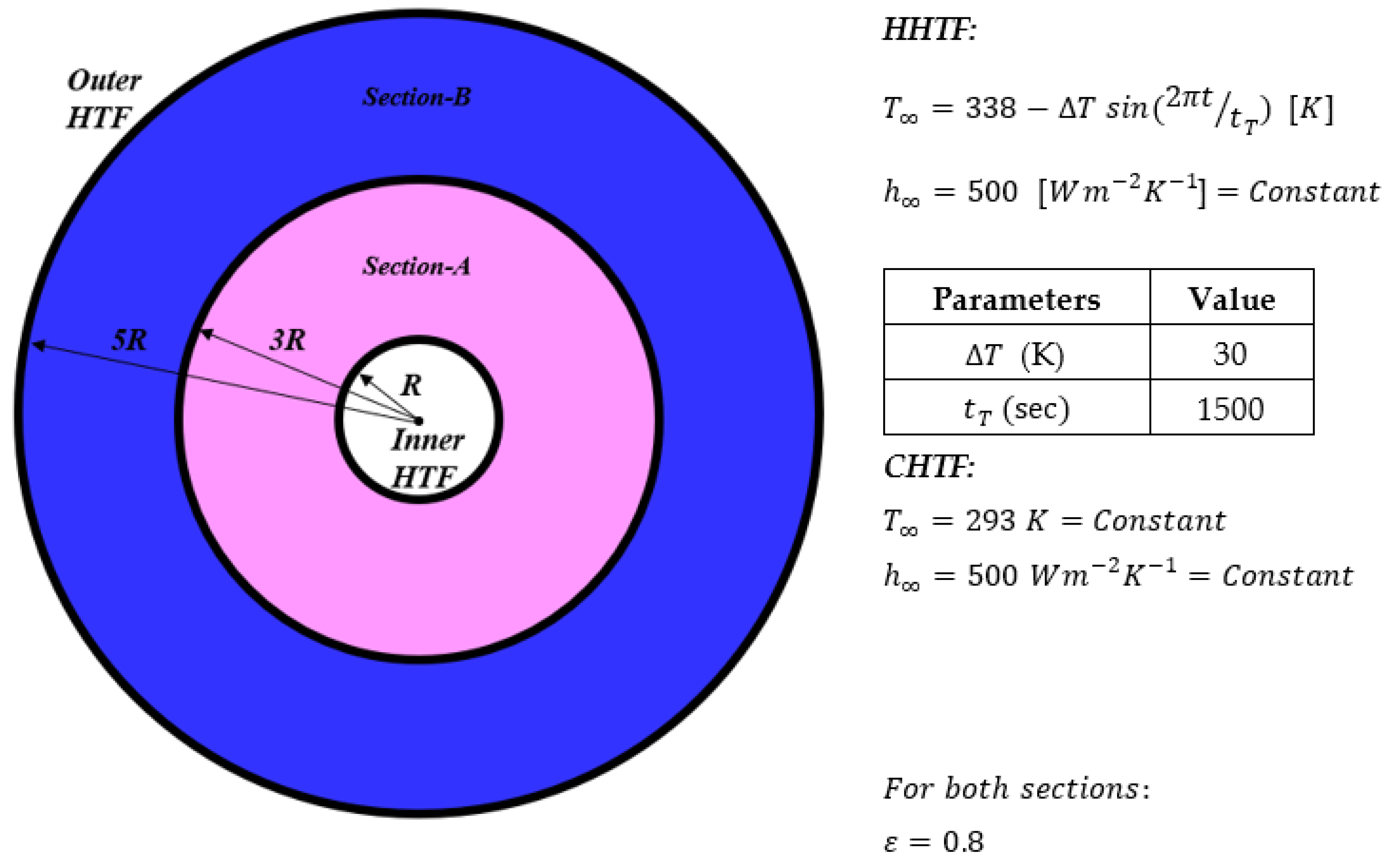
2.1. Physical Model and Boundary Conditions

As displayed in Figure 1, a double-layer PCM in an aluminum double-pipe tube, with a thickness of 1 mm and inner radius of R = 10 mm, is considered. Two sections of this annulus can be filled in various ways (arrangement type-1, type-2, or fully filled with one kind of each PCM). Two HHTFs and CHTFs with different temperatures flowed through the inner or outer cylinders in order to prepare internal heating/external cooling and external heating/internal cooling situations for PCMs to compare their reactions in terms of fluid flow and heat transfer. In addition, the effects of being initially solid or liquid at t = 0 s for both PCMs were taken into account. In each part of the discussion, the results of being fully filled with a sole PCM (RT28 or RT35) will be reported in comparison with the pair arrangements. Boundary conditions of the third kind were applied instead of hot and cold fluid flows in a way that the bulk temperature of CHTF and heat transfer coefficient (HTC) of both fluids is fixed. However, due to variable heat transfer loads during a working cycle, the bulk temperature of HHTF was variable over time, with a sinusoidal function of T = 338 − 30 × in(2πt/1500)(K). As seen from the function, a full cycle took 1500 s to be completed. In order to reduce any initial progressing flow, all the cases were evaluated for three cycles (4500 s), and as a rather stable period, the third cycle will be discussed in the results unless discussing the initial state effects. Various cases with different conditions are summarized in Table 1, and the thermo-physical properties of each PCM and aluminum containers and foam are reported in Table 2.
In order to compensate the low thermal conductivity of the phase change materials, PCMs were saturated in a porous matrix with high thermal conductivity of kp = 202.4 (W m−1 K−1), porosity of ε = 0.8 and permeability of K = 2.6 × 10⁻⁸ (m2) in both sections. Although a porous matrix considerably reduces the natural convection effects of fluid flowing through it, the effects of natural convection are taken into account. Density differences due to temperature gradient in gravitational field occur in real phase changing processes; thus, considering it helped us improve the result accuracy.
Some assumptions were considered to represent the solidification and melting procedure, which are given below.
(1)
Two-dimensional fluid flow is employed as incompressible, laminar and unsteady, with simultaneous solidification and melting processes including free convection in the liquid phase;
(2)
To initially be solid, the temperature of the whole system was chosen to be lower than the melting temperature of each PCM at t = 0 s, and higher than those for initially liquid cases;
(3)
Thermo-physical properties of each PCM are assumed to be independent of temperature except the density in liquid phase;
(4)
The Boussinesq approximation is assumed for density variation in the liquid phase [20];
(5)
Thermal resistance of aluminum walls cannot be ignored because their thickness is considerable, and conductive heat transfers through walls;
(6)
The Rayleigh number, defined as Ra = (gβ(∆T)r3)⁄αυ, is set at a fixed value of 106. ΔT stands for the amplitude of bulk HHTF temperature, g is the gravitational acceleration, r is the radius of PCM container, β is thermal expansion coefficient, and υ and α are the kinematic viscosity and thermal diffusivity, respectively;
(7)
Super-cooling effects and viscous dissipation are negligible;
(8)
Volume change in PCMs due to phase change is insignificant;
(9)
In annulus walls, no slip boundary conditions are employed;
(10)
To simulate the phase change process, the enthalpy method is employed;
(11)
In order to evaluate the flow within the porous matrix, Brinkman–Forchheimer-extended Darcy model is used [23];
(12)
The PCM is saturated in homogeneous and isotropic porous matrix.

2.2. Governing Equations

During the phase change process, both conduction and natural convection mechanisms of heat transfer take place in aluminum containers, solid and liquid phases of PCMs. According to the governing equations of the problem, the continuity and momentum conservation equation can be written as below:
Continuity:
u x + v y = 0
Momentum:
ρ ( u t + u u x + v u y ) = μ ( 2 u x 2 + 2 u y 2 ) P x + S u
ρ ( v t + u v x + v v y ) = μ ( 2 v x 2 + 2 v y 2 ) P y + S v
where S u and S v , source terms in momentum equations, are calculated as:
S u = A m u s h ( 1 γ ) 2 γ 3 + δ   u μ K u ρ C i K | u | u
S v = A m u s h ( 1 γ ) 2 γ 3 + δ   v μ K v ρ C i K | v | v + ρ r e f g β ( T T r e f )
{ γ = 1 T > T m 0 < γ < 1 T = T m γ = 0 T < T m
K d p 2 = 0.00073 ( 1 ε ) 0.224 ( d f d p ) 1.11
C i = 0.00212 ( 1 ε ) 0.132 ( d f d p ) 1.63
d f d p = 1.18 1 ε 3 π ( 1 1 e ( 1 ε ) / 0.04 )
Momentum sink, which is associated with the phase change of PCMs, appears in Equations (4) and (5) as the first item on the right-hand side (RHS), in which Amush is mushy zone constant. For the fully solidified regions, γ = 0, and in order to avoid infinity quantity for momentum sink term, a very small value was added to the denominator of the fraction [30]. The second and third terms on the RHS of Equations (4) and (5) stand for the flow resistance due to the porous media. Here, K is the permeability (m2) and Ci is the inertia coefficient which can be calculated by Equations (7) and (8), respectively [31]. The fourth item on the RHS of Equation (5) reflects the buoyancy-driven flow caused by temperature gradient and thermal expansion of the liquid phase of the PCMs. The liquid fraction during the phase change process, γ, is introduced in Equation (6). In Equations (7) and (8), ε is the medium porosity, and df and dp (m) are fiber and pore diameters, coupled quantities related to the porous density and porosity of the medium which satisfies Equation (9) [32].
Energy balance:
[ ( 1 ε ) ( ρ C p ) p o r + ε ( ρ C p ) P C M ] T t + ( ρ C p ) P C M ( u T x + v T y ) = λ e ( 2 T x 2 + 2 T y 2 ) ε ρ L γ t
where λe is the effective thermal conductivity, which can be analytically obtained according to the porous aluminum foam, as given below [31].
λ e = 3 2   [ 0.09 ψ λ P C M + 1 3 ( 1 + ψ ) ( λ p o r λ P C M ) + 0.91 ψ λ P C M + 2 3 ψ ( λ p o r λ P C M ) + 3 2 ψ λ P C M + 0.12 3 ψ ( λ p o r λ P C M ) ] 1
in which ψ is defined as:
ψ = 0.09 + 0.0081 + 2 3   3 ( 1 ε ) [ 2 0.09 ( 1 + 4 3 ) ] 2 3 ( 1.91 0.36 3 )

2.3. Numerical Model
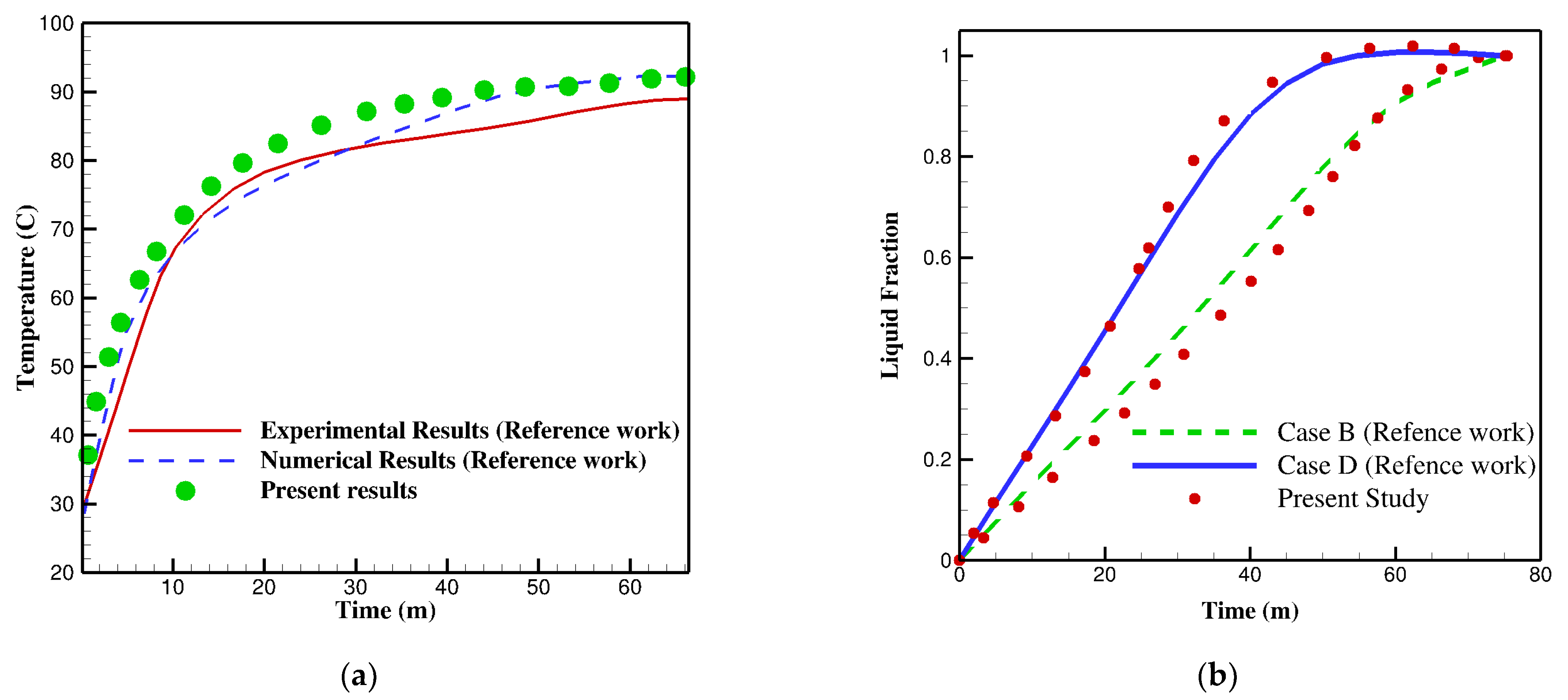
The numerical study was conducted by employing the CFD software package of ANSYS FLUENT V18. The double-precision finite volume method (FVM) was applied to solve the governing equations, the PRESTO scheme was selected for discretization of the pressure term, and second-order upwind was employed to discretize the convective terms of momentum and energy equations. Unstructured triangular cells, which are fine enough in the vicinity of walls due to the higher gradient of quantities, are used for meshing the geometry. In all equations, the convergence criterion is set to be 10−8. The under-relaxation factors of the governing equations, including continuity, momentum and energy, are 0.5, 0.3 and 0.8, respectively. These factors help for better convergence of the solutions.

2.4. Validation

In order to validate the accuracy of the present numerical simulation, the melting process of a PCM inside a triplex tube heat exchanger, introduced by Al-Abidi et al. [33], was regenerated. An initial temperature of 27 °C was set for the PCM (RT82), and HTF, which has a temperature of 90 °C, flowed through the inner tube to initiate melting. Figure 2 displays the simulation results from the current methodology and data of [33] for average temperature and liquid fraction variations of PCM over the time. Based on these comparisons, the accuracy of present numerical model was established.

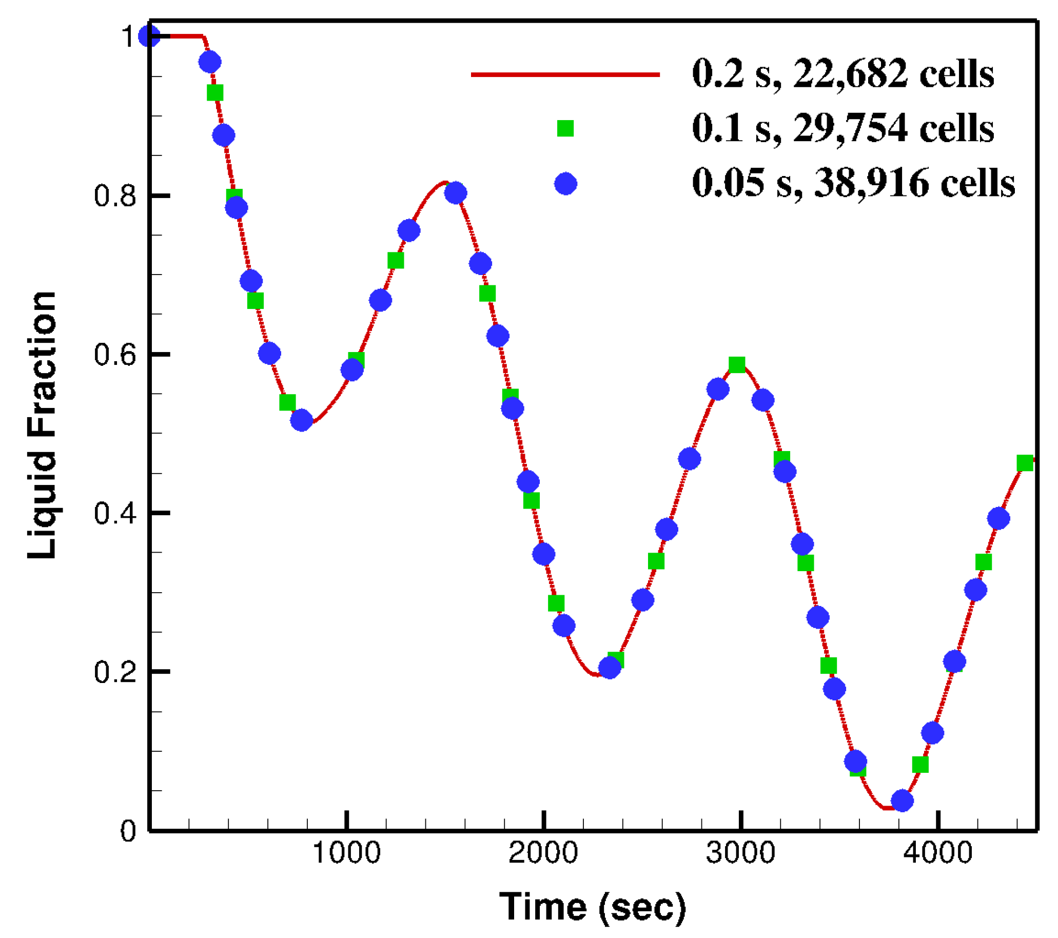
2.5. Mesh and Time Step Independency

Mesh and time step size of the numerical modeling need to be assessed to make sure that they are small enough and do not affect the simulation results. To do this, a random case which included a two-layer PCM was tested with three different cell numbers and time-step sizes (case 6 in Table 1). Results for a liquid fraction of section-B (filled with RT28) are displayed in Figure 3 for three various meshes and time step sizes. As shown, the results of all three sizes are very close to each other; therefore, to reduce the computational costs as well as present accurate data, a time step size of 0.2 s and mesh size of 22,682 cells were chosen.

3. Results and Discussion

3.1. PCM Arrangements

Firstly, the results of two different arrangements of PCMs in sections A and B were analyzed. To do this, we considered case 1 and case 2 (Table 1), in which the internal heating and external cooling boundary conditions along with initially solid phase states for both sections were applied. The results for arrangement type-1 (RT28 in section A and RT35 in section B) and arrangement type-2 (RT35 in section A and RT28 in section B) are displayed in Figure 4 and Figure 5 in the forms of liquid fraction and average temperature history. Comparisons between Figure 4a,b pointed out that by putting RT28 in section A and RT35 in section B, RT35 will respond to the boundary conditions in its sensible form, remaining entirely in its solid phase for the whole period, which is rooted in the fact that this section is located in the vicinity of cold HTF in this arrangement, whereas RT28 mostly reacts in its latent heat transfer form, oscillating between 1 and almost 0.3 in terms of liquid fraction. On the other hand, by changing the order of PCMs, in spite of the fact that RT35 is located near the hot HTF, it exhibits a minor reaction compared with RT28. This fact, which refers to the thermo-physical properties of PCMs, is clear from the variations in liquid fraction over time in Figure 4a,b.
The locally averaged temperatures of each PCM in each section are illustrated in Figure 5a,b for both arrangements. As mentioned above, only the third cycle is discussed to analyze these figures. Firstly, it is notable that, as the system is cooling from the outer layer, in both arrangements, the average temperature of section B (the outer section) is lower than that of section A. Focusing on the third cycle (3000 to 4500 s), in arrangement type-1, the average temperature of section A ranges from 300.5 to 307.5 K, and for section B, it spans from 298.5 to 303.5 K. This means that, in the form of arrangement type-1, the locally averaged temperature of both sections reaches about 2 K more than their corresponding sections in type-2. According to Figure 5b, even though the average temperature of RT35 does not reach its melting temperature (308 K), it melts in some timeframes. This can be justified by checking the maximum and minimum temperatures within each section (See Figure 8). As shown, although the average temperature of section A is less than 305 K, the temperature of some points in section A hits the maximum of 310 K.

3.2. Effects of Employing Double-Layer PCM

In this section, the effects of employing double-layer PCM (with each arrangement) instead of using a single kind of PCM are evaluated under the same conditions. For this reason, cases 1–4 were considered and variations in liquid fraction and average local temperature versus time were compared. Cases 3 and 4 stand for tubular heat exchangers in which a single kind of PCM is used. Figure 6a displays the liquid fraction history when both sections are entirely filled with RT28. It is obvious that either solid or liquid phases appear in both sections. Being influenced by nearby HTF, section A faces 100% of the liquid phase in some periods while the reverse is true for section B. The same information for RT35 is shown in Figure 6b. It is clear that section B remains at the solid phase without melting for the whole cycle, but in section A, RT35 melts up to 0.35 of liquid fraction in some timeframes. Due to the thermo-physical properties of each PCM, comparing cases 3 and 4, the system responds relatively more with its latent form when it is fully filled with RT28. Based on Figure 7a, b, the locally average temperature of the system when it is completely filled with RT28 oscillates between 299 and 304.5 K, whereas the relevant values for RT35 are 295.5 and 307.5 K. Thus, it can be concluded that the system temperature oscillates with a wider amplitude for case 4. This phenomenon is expected from Figure 6, a system which comparatively reacts more with its latent heat form, will face less temperature fluctuation.
By taking all four mentioned cases into consideration, it can be concluded that in both arrangement type-1 and that fully filled with RT35, section B will remain in solid state for the whole period, whereas the solid–liquid phase will appear in section A, reacting more with the latent heat transfer mechanism for the form of arrangement type-1. Under the same conditions, filling the heat exchanger fully with RT28 and with arrangement type-2, lead to both solid and liquid phases in either section with a difference that liquid percentage of section A are relatively less in arrangement type-2. Comparing Figure 5 and Figure 7, case 4 leads to the largest amplitude of locally average temperature oscillation, whereas this quantity is the lowest for case 3.
Figure 8 depicts the temperature variation of PCMs in sections A and B during the third period for cases 1–4. The CHTF with fixed bulk temperature flows around section B; therefore, this section experiences relatively minor temperature fluctuation compared with section A, which is located in the vicinity of the HHTF with variable bulk temperature. In addition, for all cases, the minimum temperature of the system has been captured in section B and the maximum quantity has been reported in section A.

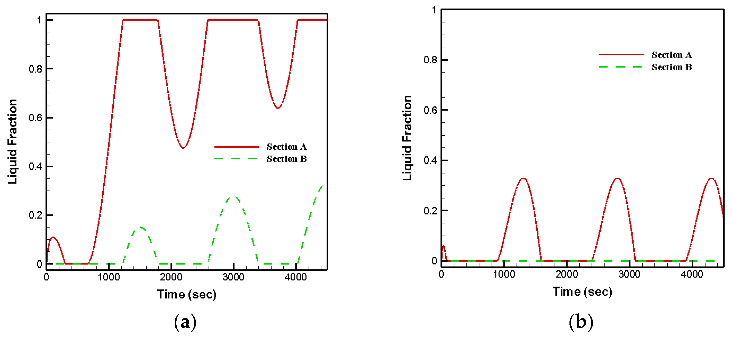
3.3. Effects of Various Boundary Conditions

That each hot or cold HTF flows through inner or outer sections of the heat exchanger may play a significant role in the heat transfer rate. In order to examine the effects of the order of each HTF, both internal heating/external cooling (first B.C.) and internal cooling/external heating (second B.C.) conditions with initially solid phase status are applied and the results are reported in the form of liquid fraction in Figure 9 and Figure 10. Based on Figure 9, under the second B.C., in arrangement type-1, section A stays in the liquid phase for the entire period. Section B follows almost the same trend, with a minor solidification in some timeframes (less than 10%). However, under the first B.C., section B remains in the solid phase completely, whereas approximately 65% of section A experiences the phase change process. For arrangement type-2, under the second B.C., phase change does not occur in section B, staying in the liquid phase for the whole period, but up to 22% of PCM solidifies in section A. In contrast, a relatively high volume of PCMs changes phase under the first B.C. Notably, compared with the first B.C., most of the PCM stays in the liquid phase in both sections under the second B.C. In the second B.C., hot HTF flows through the outer cylinder, extending the heat transfer surface in comparison with the first B.C.; then, the amount of heat absorbed by the system rises under the second B.C.

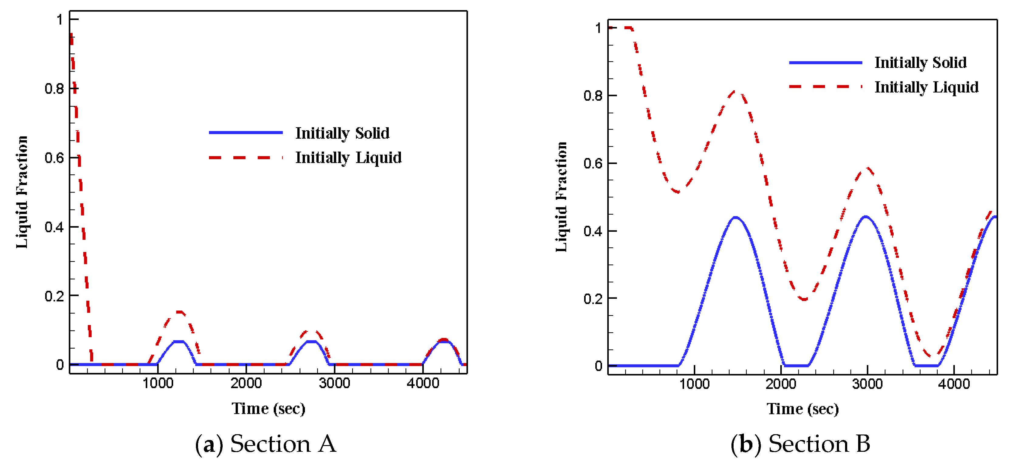
3.4. Effects of Initial Status

Figure 11 and Figure 12 show the liquid fractions of both arrangements under the internal heating and external cooling boundary conditions for both initially solid/liquid phase states. It can be observed from the figures that the liquid fractions of two initial various phase states become closer as the time passes, and become completely equal for the third period. Therefore, with the exception of some earlier cycles, the initial phase status does not affect heat transfer and fluid flow features of PCMs in each arrangement.

4. Conclusions

Numerical evaluations have been conducted to investigate the solidification and melting processes of multi-layer phase change materials in a triplex tub heat exchanger. RT28 and RT35 were utilized in four different ways to fill the sections of an annulus channel. Governing equations, including conduction and convection heat transfer, were solved by the finite volume numerical approach. Controlling parameters such as arrangements of layers, orders of heat transfer fluid for cold and hot flows and initial conditions of phase change materials were discussed. Based on the outcomes of the model, various notable arguments can be made. Some of the most important arguments are stated below.
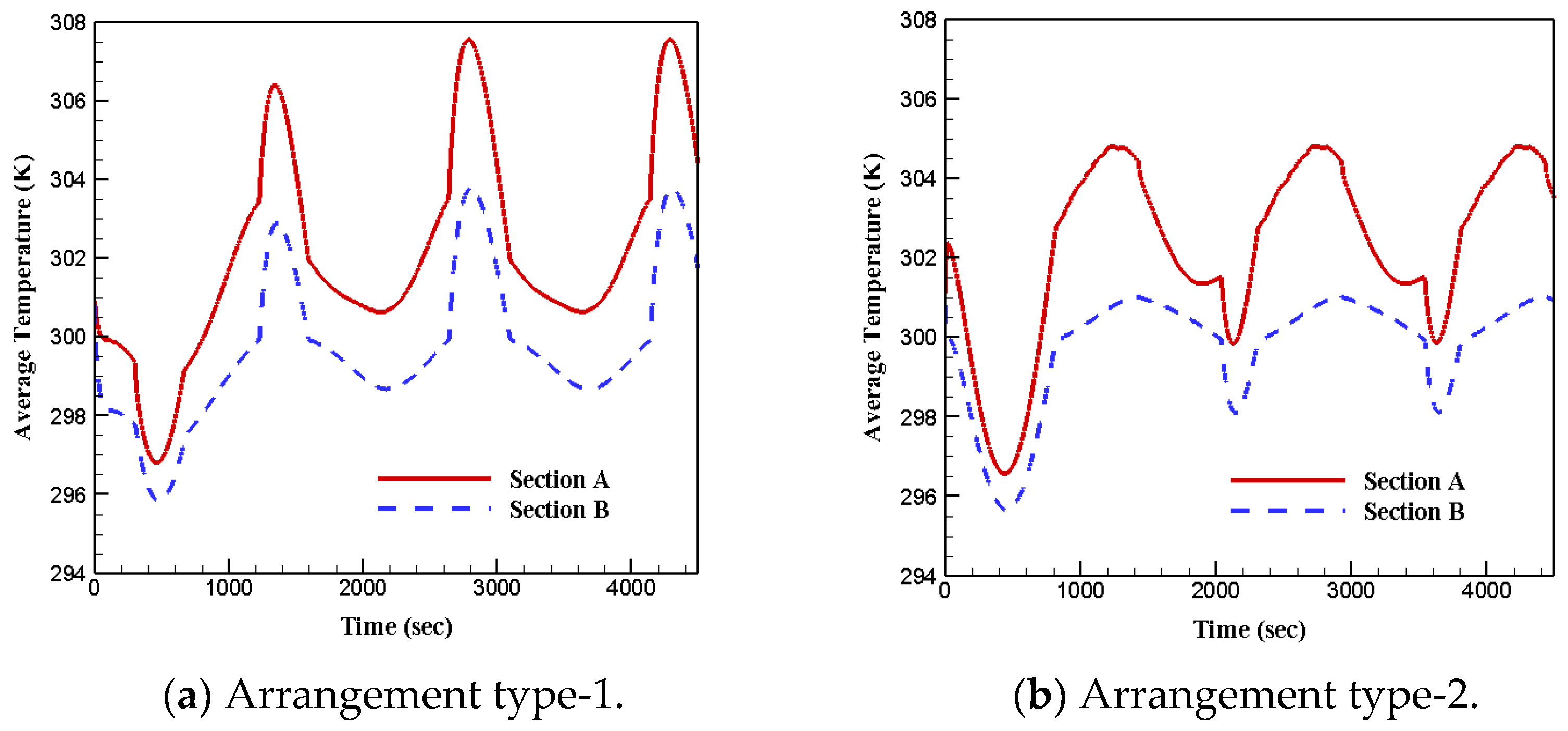
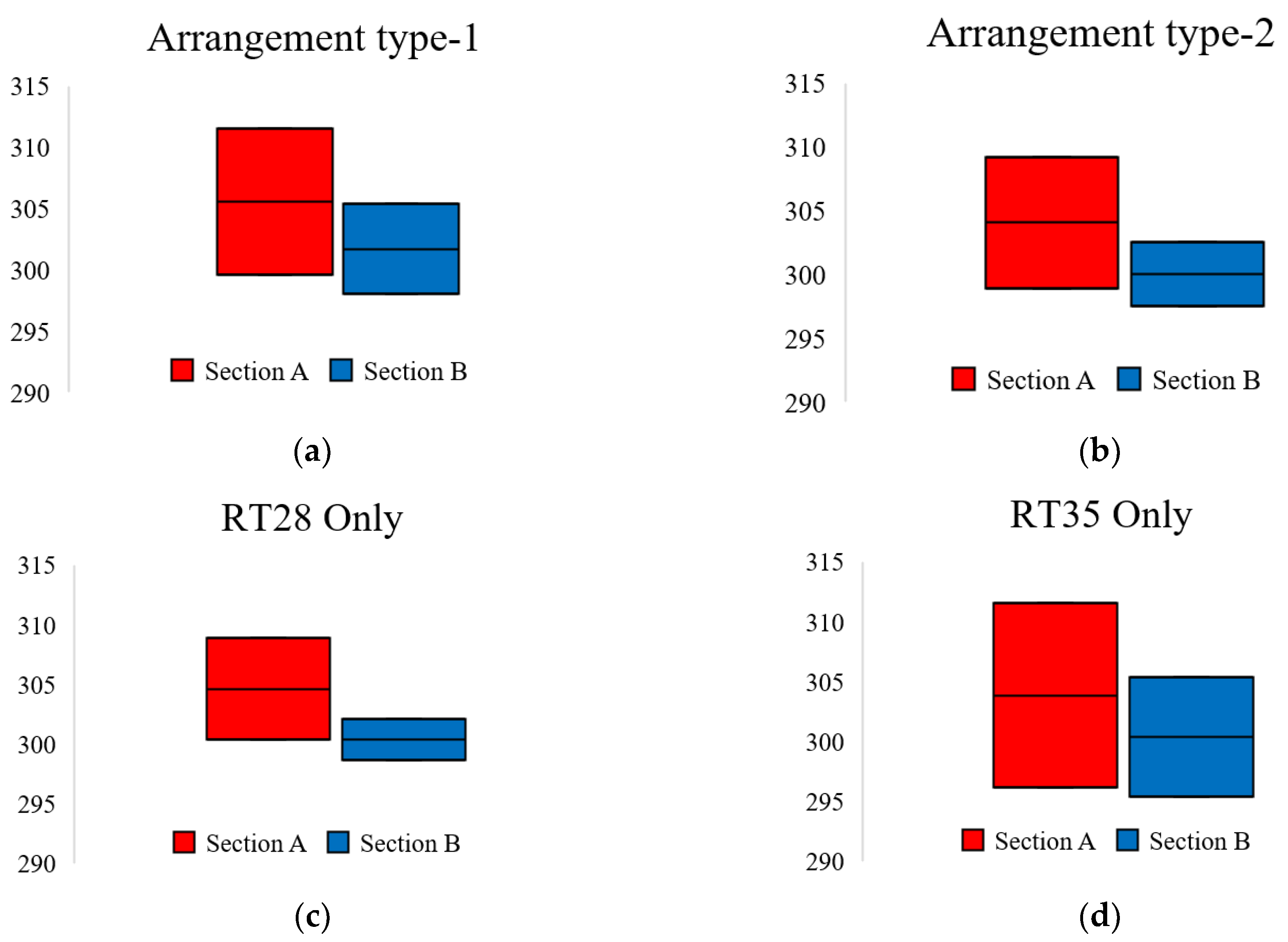
  • The amplitude of locally average temperature oscillation for case 3 was the lowest, whereas case 4 fluctuated with the widest amplitude among the four cases;
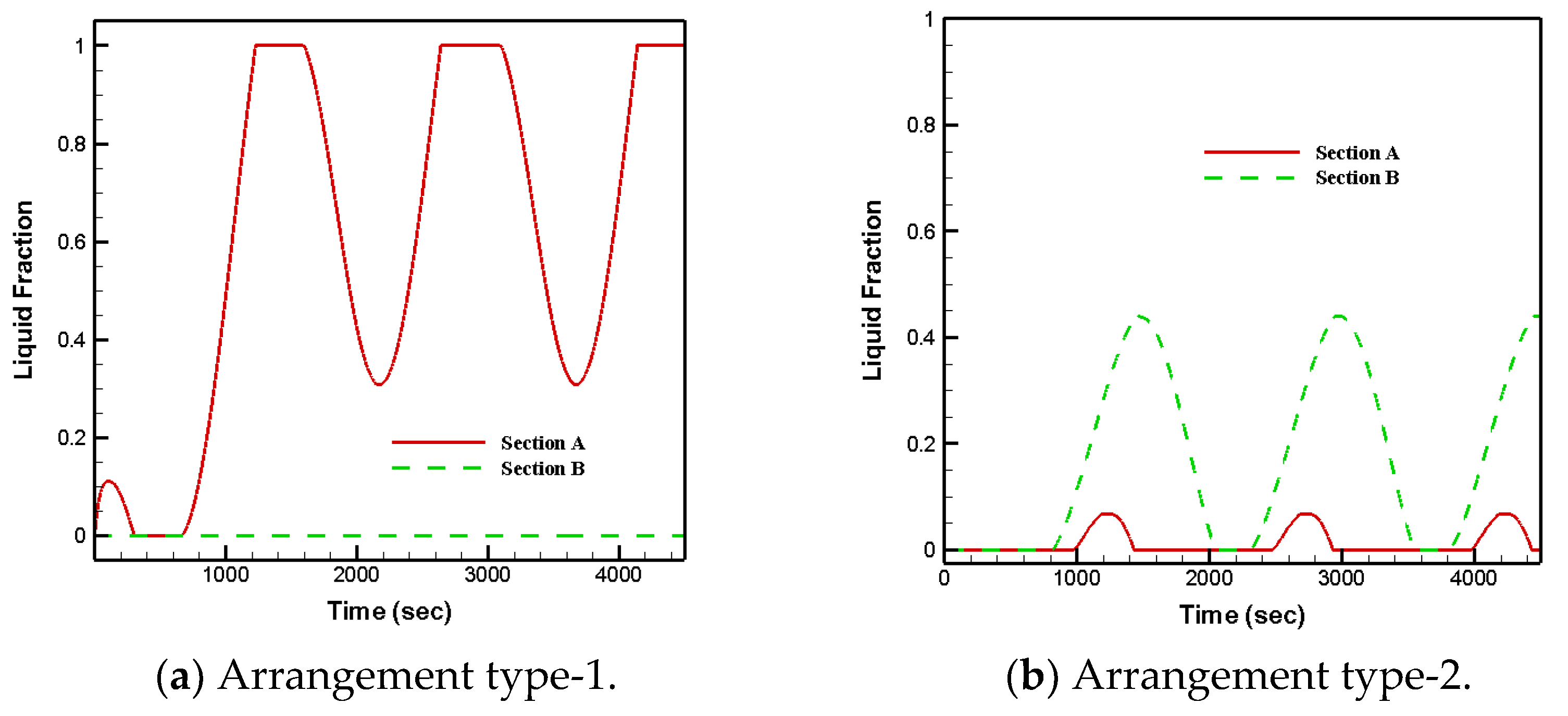
  • Arrangement type-2 and that fully filled with RT28 led to solid–liquid phase changes in both sections;
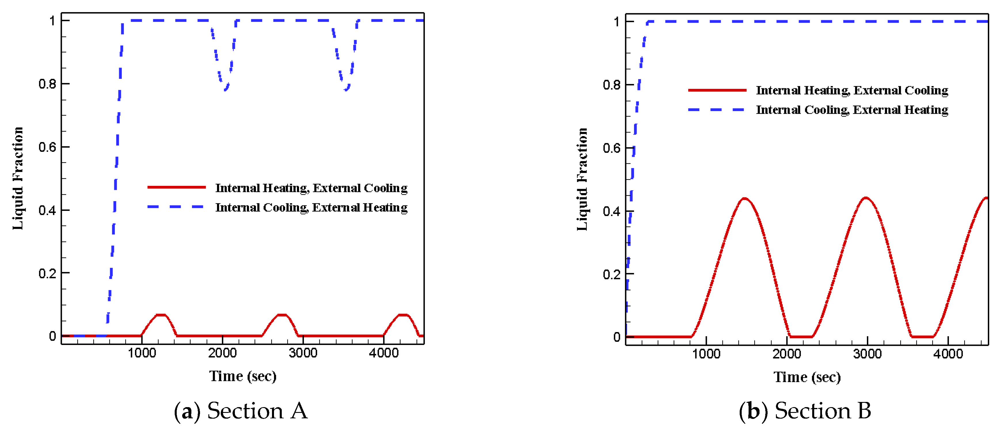
  • Arrangement type-1 and that fully filled with RT35 led to the samples remaining at solid phase for the entire period in section B;
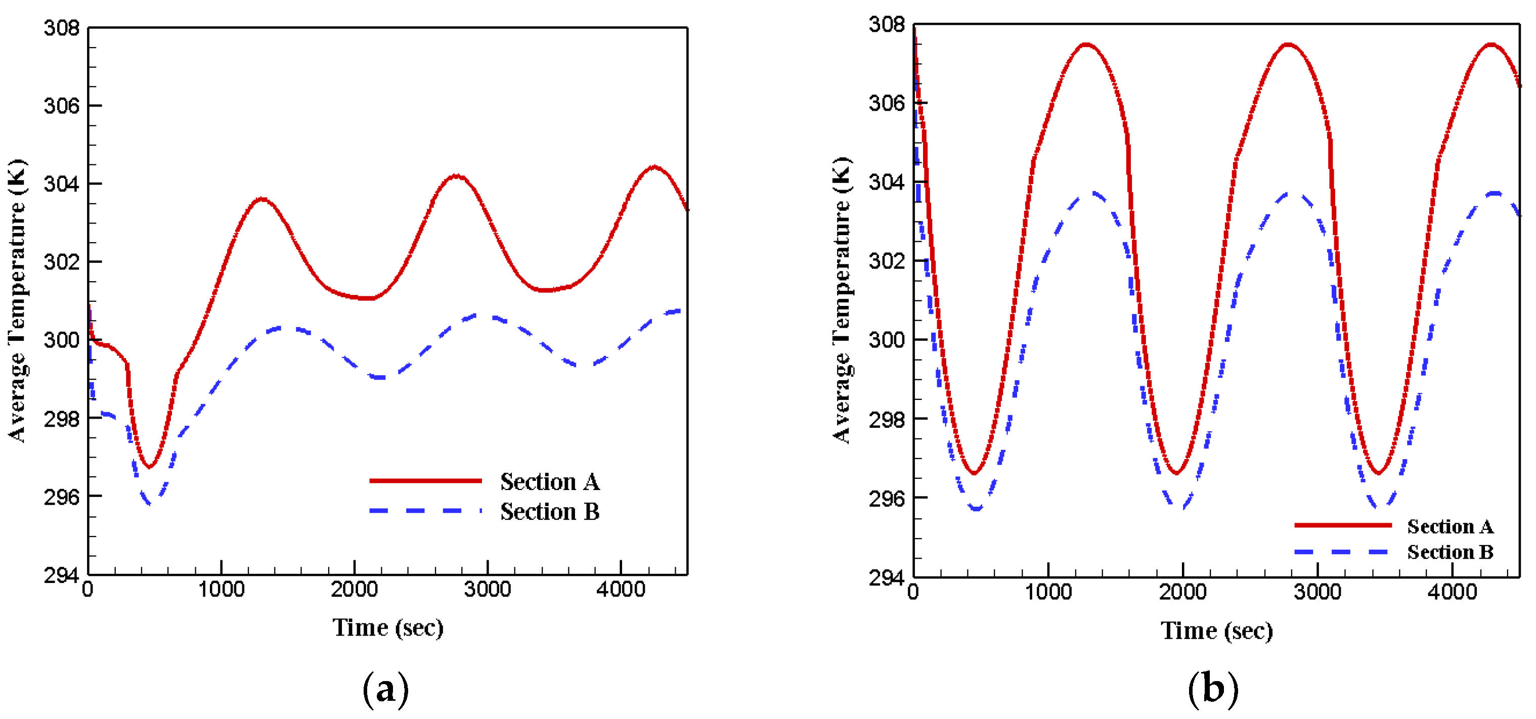
  • Under the first boundary condition, the temperature of section A spanned wider than section B for all four cases;
  • Under the first boundary condition, the lowest temperature was seen in section B and the highest was captured in section A;
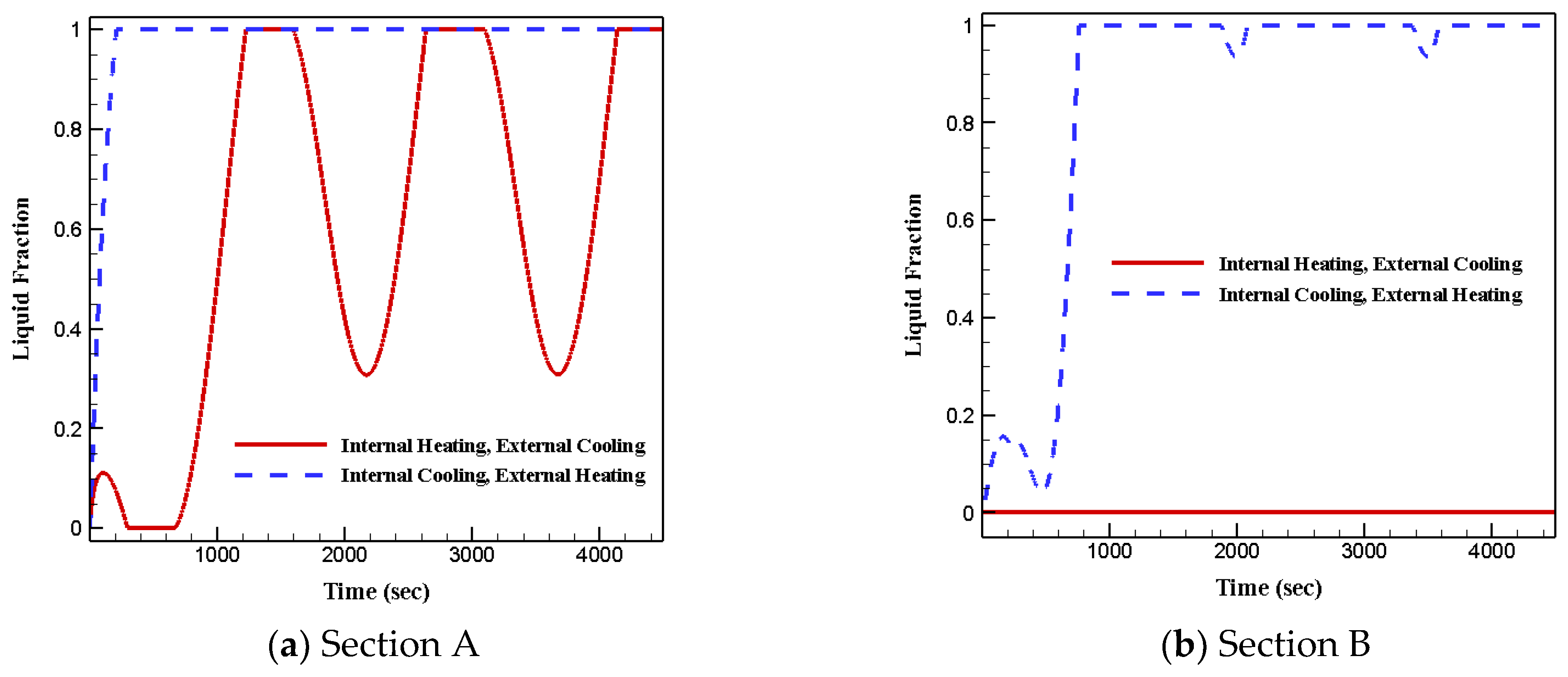
  • Under the second boundary condition, most of the phase change materials in both sections stayed in liquid phase due to the extended heat transfer surface;
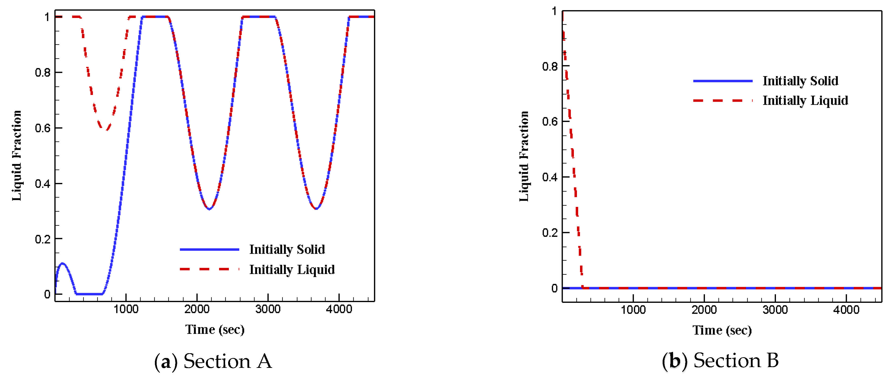
  • The initial phase status of phase change materials does not affect heat transfer and fluid flow features.
These remarkable findings and the understanding represent potential for advancing this research field and will be significant for developing an energy-efficient hybrid heat exchanger based on phase change materials.

Author Contributions

Conceptualization, A.M.S. and M.E.S.; methodology, A.M.S. and M.E.S.; software, A.M.S. and M.E.S.; validation, A.M.S.; formal analysis, A.M.S. and M.E.S.; investigation, A.M.S. and M.E.S.; resources, M.S., M.I.H.K. and S.C.S.; data curation, A.M.S.; writing—original draft preparation, A.M.S. and M.E.S.; writing—review and editing, M.S., M.I.H.K. and S.C.S.; visualization, A.M.S.; supervision, M.S., M.I.H.K. and S.C.S. All authors have read and agreed to the published version of the manuscript.

Funding

This research received no external funding.

Institutional Review Board Statement

Not applicable.

Informed Consent Statement

Not applicable.

Data Availability Statement

Numerical data will be available on request.

Conflicts of Interest

The authors declare no conflict of interest.

References

  1. Bahiraei, M.; Khosravi, R.; Heshmatian, S. Assessment and optimization of hydrothermal characteristics for a non-Newtonian nanofluid flow within miniaturized concentric-tube heat exchanger considering designer’s viewpoint. Appl. Therm. Eng. 2017, 123, 266–276. [Google Scholar] [CrossRef]
  2. Bahiraei, M.; Naghibzadeh, S.M.; Jamshidmofid, M. Efficacy of an eco-friendly nanofluid in a miniature heat exchanger regarding to arrangement of silver nanoparticles. Energy Convers. Manag. 2017, 144, 224–234. [Google Scholar] [CrossRef]
  3. Bahiraei, M. Particle migration in nanofluids: A critical review. Int. J. Therm. Sci. 2016, 109, 90–113. [Google Scholar] [CrossRef]
  4. Mirzaei, P.A.; Haghighat, F. Modeling of phase change materials for applications in whole building simulation. Renew. Sustain. Energy Rev. 2012, 16, 5355–5362. [Google Scholar] [CrossRef]
  5. El-Sawi, A.; Haghighat, F.; Akbari, H. Assessing long-term performance of centralized thermal energy storage system. Appl. Therm. Eng. 2014, 62, 313–321. [Google Scholar] [CrossRef]
  6. Joybari, M.M.; Haghighat, F.; Moffat, J.; Sra, P. Heat and cold storage using phase change materials in domestic refrigeration systems: The state-of-the-art review. Energy Build. 2015, 106, 111–124. [Google Scholar] [CrossRef]
  7. Bastani, A.; Haghighat, F. Expanding Heisler chart to characterize heat transfer phenomena in a building envelope integrated with phase change materials. Energy Build. 2015, 106, 164–174. [Google Scholar] [CrossRef]
  8. Khan, Z.; Khan, Z.; Ghafoor, A. A review of performance enhancement of PCM based latent heat storage system within the context of materials, thermal stability and compatibility. Energy Convers. Manag. 2016, 115, 132–158. [Google Scholar] [CrossRef]
  9. Shin, D.; Banerjee, D. Enhanced thermal properties of SiO2 nanocomposite for solar thermal energy storage applications. Int. J. Heat Mass Transf. 2015, 84, 898–902. [Google Scholar] [CrossRef] [Green Version]
  10. Tao, Y.B.; Lin, C.H.; He, Y.L. Preparation and thermal properties characterization of carbonate salt/carbon nanomaterial composite phase change material. Energy Convers. Manag. 2015, 97, 103–110. [Google Scholar] [CrossRef]
  11. Wang, F.; Zhang, C.; Liu, J.; Fang, X.; Zhang, Z. Highly stable graphite nanoparticle-dispersed phase change emulsions with little supercooling and high thermal conductivity for cold energy storage. Appl. Energy 2017, 188, 97–106. [Google Scholar] [CrossRef]
  12. Erek, A.; İlken, Z.; Acar, M.A. Experimental and numerical investigation of thermal energy storage with a finned tube. Int. J. Energy Res. 2005, 29, 283–301. [Google Scholar] [CrossRef] [Green Version]
  13. Xiao, X.; Zhang, P.; Li, M. Preparation and thermal characterization of paraffin/metal foam composite phase change material. Appl. Energy 2013, 112, 1357–1366. [Google Scholar] [CrossRef]
  14. Wei, L.C.; Malen, J.A. Amplified charge and discharge rates in phase change materials for energy storage using spatially-enhanced thermal conductivity. Appl. Energy 2016, 181, 224–231. [Google Scholar] [CrossRef] [Green Version]
  15. Wang, H.; Wang, F.; Li, Z.; Tang, Y.; Yu, B.; Yuan, W. Experimental investigation on the thermal performance of a heat sink filled with porous metal fiber sintered felt/paraffin composite phase change material. Appl. Energy 2016, 176, 221–232. [Google Scholar] [CrossRef]
  16. Pasupathy, A.; Velraj, R. Effect of double layer phase change material in building roof for year round thermal management. Energy Build. 2008, 40, 193–203. [Google Scholar] [CrossRef]
  17. Hamza, H.; Hanchi, N.; Abouelkhayrat, B.; Lahjomri, J.; Oubarra, A. Location and Thickness Effect of Two Phase Change Materials Between Layers of Roof on Energy Consumption for Air-Conditioned Room. J. Therm. Sci. Eng. Appl. 2016, 8, 021009. [Google Scholar] [CrossRef]
  18. Kanzawa, A. Thermal performance of a heat storage module using PCM’s with different melting temperatures: Mathematical modeling. ASME J. Energy Resour. Technol. 1989, 111, 152–157. [Google Scholar]
  19. Mosaffa, A.H.; Ferreira, C.I.; Talati, F.; Rosen, M.A. Thermal performance of a multiple PCM thermal storage unit for free cooling. Energy Convers. Manag. 2013, 67, 1–7. [Google Scholar] [CrossRef]
  20. Sefidan, A.M.; Sojoudi, A.; Saha, S.C.; Cholette, M. Multi-layer PCM solidification in a finned triplex tube considering natural convection. Appl. Therm. Eng. 2017, 123, 901–916. [Google Scholar] [CrossRef] [Green Version]
  21. Tian, Y.; Zhao, C.Y. A numerical investigation of heat transfer in phase change materials (PCMs) embedded in porous metals. Energy 2011, 36, 5539–5546. [Google Scholar] [CrossRef] [Green Version]
  22. Zhao, C.Y.; Lu, W.; Tian, Y. Heat transfer enhancement for thermal energy storage using metal foams embedded within phase change materials (PCMs). Sol. Energy 2010, 84, 1402–1412. [Google Scholar] [CrossRef] [Green Version]
  23. Sefidan, A.M.; Taghilou, M.; Mohammadpour, M.; Sojoudi, A. Effects of different parameters on the discharging of double-layer PCM through the porous channel. Appl. Therm. Eng. 2017, 123, 592–602. [Google Scholar] [CrossRef]
  24. Mesalhy, O.; Lafdi, K.; Elgafy, A.; Bowman, K. Numerical study for enhancing the thermal conductivity of phase change material (PCM) storage using high thermal conductivity porous matrix. Energy Convers. Manag. 2005, 46, 847–867. [Google Scholar] [CrossRef]
  25. Taghilou, M.; Sefidan, A.M.; Sojoudi, A.; Saha, S.C. Solid-liquid phase change investigation through a double pipe heat exchanger dealing with time-dependent boundary conditions. Appl. Therm. Eng. 2017, 128, 725–736. [Google Scholar] [CrossRef] [Green Version]
  26. Ismail, K.A.; Maria das Graças, E. Melting of PCM around a horizontal cylinder with constant surface temperature. Int. J. Therm. Sci. 2003, 42, 1145–1152. [Google Scholar] [CrossRef]
  27. Atal, A.; Wang, Y.; Harsha, M.; Sengupta, S. Effect of porosity of conducting matrix on a phase change energy storage device. Int. J. Heat Mass Transf. 2016, 93, 9–16. [Google Scholar] [CrossRef]
  28. Taghilou, M.; Talati, F. Numerical investigation on the natural convection effects in the melting process of PCM in a finned container using lattice Boltzmann method. Int. J. Refrig. 2016, 70, 157–170. [Google Scholar] [CrossRef]
  29. Talati, F.; Taghilou, M. Lattice Boltzmann application on the PCM solidification within a rectangular finned container. Appl. Therm. Eng. 2015, 83, 108–120. [Google Scholar] [CrossRef]
  30. Xu, Y.; Ren, Q.; Zheng, Z.J.; He, Y.L. Evaluation and optimization of melting performance for a latent heat thermal energy storage unit partially filled with porous media. Appl. Energy 2017, 193, 84–95. [Google Scholar] [CrossRef]
  31. Calmidi, V.V.; Mahajan, R.L. Forced convection in high porosity metal foams. Trans.-Am. Soc. Mech. Eng. J. Heat Transf. 2000, 122, 557–565. [Google Scholar] [CrossRef]
  32. Calmidi, V.V. Transport Phenomena in High Porosity Fibrous Metal Foams; University of Colorado at Boulde: Boulder, CO, USA, 1998. [Google Scholar]
  33. Al-Abidi, A.A.; Mat, S.; Sopian, K.; Sulaiman, M.Y.; Mohammad, A.T. Internal and external fin heat transfer enhancement technique for latent heat thermal energy storage in triplex tube heat exchangers. Appl. Therm. Eng. 2013, 53, 147–156. [Google Scholar] [CrossRef]
Figure 1. Schematic of the physical model and boundary conditions.
Energies 15 03465 g001
Figure 2. The comparison between the results of current numerical method and numerical and experimental data of [33]. (a) Time series of temperature, (b) Time series of liquid fraction.
Energies 15 03465 g002
Figure 3. Liquid fraction of RT28 for various meshes and time step sizes (for case 6 in Table 1).
Energies 15 03465 g003
Figure 4. Liquid fraction of each PCM in each section for arrangement type-1 (RT28 in section A and RT35 in section B) and arrangement type-2 (RT35 in section A and RT28 in section B). Initial status: Solid, Inner wall: HHTF, Outer Wall: CHTF.
Energies 15 03465 g004
Figure 5. Average temperature of each PCM in each section for arrangement type-1 (RT28 in section A and RT35 in section B) and arrangement type-2 (RT35 in section A and RT28 in section B). Initial status: Solid, Inner wall: HHTF, Outer Wall: CHTF.
Energies 15 03465 g005
Figure 6. Liquid fraction with respect to time when both sections are filled by (a) RT28, (b) RT35. Initial status: Solid, Inner wall: HHTF, Outer Wall: CHTF.
Energies 15 03465 g006
Figure 7. Average temperature with respect to time when both the sections are filled by (a) RT28, (b) RT35. Initial status: Solid, Inner wall: HHTF, Outer Wall: CHTF.
Energies 15 03465 g007
Figure 8. Minimum and maximum temperatures captured in each section during the third period (cases 1–4 in Table 1) for (a) Arrangement type-1, (b) Arrangement type-2, (c) RT28 Only, (d) RT35 Only.
Energies 15 03465 g008
Figure 9. Liquid fraction of arrangement type-1 for two various boundary conditions. Initially Solid, case 1 compared with case 7.
Energies 15 03465 g009
Figure 10. Liquid fraction of arrangement type-2 for two various boundary conditions. Initially Solid, case 2 compared with case 8.
Energies 15 03465 g010
Figure 11. Liquid fraction of arrangement type-1 for two various initial conditions. Inner wall: HHTF, Outer Wall: CHTF, case 1 compared with case 5.
Energies 15 03465 g011
Figure 12. Liquid fraction of arrangement type-2 for two various initial conditions. Inner wall: HHTF, Outer Wall: CHTF, case 2 compared with case 6.
Energies 15 03465 g012
Table 1. Different cases of the present study.
CasesSection ASection BInitial Status of Section AInitial Status of Section BInner HTFOuter HTF
1RT28RT35SolidSolidHotCold
2RT35RT28SolidSolidHotCold
3RT28SolidSolidHotCold
4RT35SolidSolidHotCold
5RT28RT35LiquidLiquidHotCold
6RT35RT28LiquidLiquidHotCold
7RT28RT35SolidSolidColdHot
8RT35RT28SolidSolidColdHot
Table 2. Thermo-physical properties of PCMs and aluminum.
Thermo-Physical PropertiesRT 28RT 35Aluminum
Density ( kg   m 3 )8108202719
C p ( J   kg 1 K 1 )19002100871
Thermal   Conductivity   ( W   m 1   K 1 ) 0.20.2202.4
Dynamic   Viscosity   ( kg   m 1   s 1 ) 0.00250.0027-
Melting   Heat   ( J   kg 1 ) 245,000157,000-
Solidification   Temperature   ( K ) 301308-
Publisher’s Note: MDPI stays neutral with regard to jurisdictional claims in published maps and institutional affiliations.

