Article

Internal Film Cooling with Discrete-Slot Injection Orifices in Hydrogen/Oxygen Engine Thrust Chambers

1
School of Astronautics, Beihang University, Shahe Campus, 9 Nansan Street, Shahe Higher Education Park, Changping District, Beijing 102206, China
2
Beijing Electro-Mechanical Engineering Institute, 40 Yungangbeili, Fengtai District, Beijing 100074, China
3
Beijing Key Laboratory of Cryogenic Technology Research, Beijing Institute of Astronautical System Engineering, 1 East Highland South Rd, Fengtai District, Beijing 100076, China
*
Author to whom correspondence should be addressed.
Energies 2022, 15(9), 3459; https://doi.org/10.3390/en15093459
Submission received: 24 March 2022 / Revised: 17 April 2022 / Accepted: 5 May 2022 / Published: 9 May 2022

Abstract

:
In the present study, a hydrogen and oxygen heat-sink engine thrust chamber and the corresponding injection faceplate with discrete slot orifices are devised to study the cooling performance near the faceplate region. Moreover, a set of experiments and numerical simulations are conducted to evaluate the effects of various factors on combustion performance and film cooling efficiency. According to the obtained result, the circumferential cooling efficiency has an M-shaped distribution in the near-injector region. Furthermore, it has been discovered that when the film flow ratio increases, so does the cooling efficiency. This is especially more pronounced in the range of 30–80 mm from the faceplate. The cooling efficiency is found to be proportional to the film flow rate ratio’s 0.4 power. Compared with the slot thickness, the reduction in the slot width is more beneficial in improving the cooling efficiency, and the advantage is more prominent for small film flow ratios. In addition, when the amount of coolant is not enough, the cooling effect of the discrete slot film orifice is better than that of the common cylindrical orifice. The present article demonstrates that setting the area ratio of the adjacent film orifices is an effective way to reduce the uneven circumferential distribution of the wall surface temperature.

1. Introduction

The reusable launch vehicle (RLV) is an ideal choice for performing space transport missions. Studies show that these vehicles have high reliability and low launch cost and turnaround time [1,2]. Furthermore, reusable rocket engines (RREs) have a high level of performance and have been commonly used in the powertrain of RLVs, including SSME, Vulcain X, and RD-191 Merlin1D [3]. Hot gas created by the chemical reaction of extremely energetic propellants flows into the combustion chamber in RRE, releasing a tremendous quantity of energy. Then the expanded gas passes through the nozzle, thereby creating thrust and accelerating the RLV. Further research reveals that exceptionally high heat flux levels and temperature gradients exist near the nozzle throat and injector [4]. Accordingly, it is essential to perform effective thermal protection methods to ensure efficient functioning and the structural integrity of the RLV in harsh thermal environments [5]. Film cooling has recently gained popularity as a viable means of protecting the chamber wall from hot combustion gases. A layer of coolant fluid is injected between the wall and the hot gas in this manner [6].
In the past few years, numerous numerical simulations [7,8] and experiments [9,10] have been conducted to improve the performance of film cooling. NASA carried out experiments on film cooling in the early stages of the shuttle engine [11]. In this regard, a gaseous oxygen combustion chamber with a small thrust was used, and the gas film was supplied by a separate pipeline, and a thin-walled cylinder structure was used as the downstream test section. The obtained test findings demonstrated that the cooling efficiency of the downstream adiabatic wall can be expressed by the Hatch–Papel correlation. Shine et al. [12] carried out experiments and studied the effects of various parameters affecting cylindrical and composite film orifices on the cooling efficiency. The results obtained illustrate that the coolant injection parallel to the axial direction can extend the gas film coverage. However, the wall protection effect of the tangential jet is generally poor compared with other schemes.
Bayraktar et al. [13] found that the maximum cooling efficiency can be achieved when the blowing ratio and the inclination angle are set to 2.0 and 30°, respectively. Moreover, it was found that there is a certain correlation between the cooling efficiency and the counter-rotating vortex pair. Betti et al. [14] ignored the injection and combustion of the propellant and proposed a pseudo-injector model to record the heat flux in thrust chambers with film cooling under various chamber pressures. Then the model was verified through experimental data. According to the studies, heat flux in the region of the near-injector is reduced by the film medium. This effect is especially more pronounced at high chamber pressures.
Most investigations on film cooling have focused on the cooling effect of the turbine blade [15,16,17] or the body section [18,19]. However, Song et al. [20] showed that intense mixing and burning of propellants generate complex thermal loads in the vicinity of the faceplate, which suggests that the thermal protection of the chamber head section faces enormous problems. Furthermore, studies [21,22] showed that the temperature peak of the thrust chamber with a long cylindrical section generally appears in the head of the combustor rather than the throat. Nevertheless, there is not enough information about the thermal protection scheme in the near-injector region. As a result, there is a pressing need for more research in this area.
Considering the performed literature survey, numerical simulations and experiments will be conducted to investigate how discrete-slot orifices affect the film cooling performance in the near-injector region. To this end, the design of a sub-scaled heat-sink thrust chamber and faceplate with discrete-slot orifices is presented. The primary purpose of the paper is to determine the effect of different parameters on the gas film cooling efficiency, such as the film flow ratio, slot width, and slot thickness. Moreover, the impact of the film orifice shape on cooling efficiency is investigated. Then, experimental data are analyzed to improve the cooling efficiency. The obtained results from hot tests are used to verify the numerical simulation. Then, the orthogonal tests are conducted to analyze the effects of design specifications on the combustion performance and cooling efficiency of the thrust chamber.

2. Experimental Equipment and Computational Methodology

2.1. Experimental Equipment

The test platform consists of a gas supply system, a gas film supply system, a measuring device and control room, and a test cell. Gaseous hydrogen and oxygen serve as the fuel and oxidizer, respectively, in the combustion chamber without regard to propellant atomization and evaporation. High-pressure gas tanks with adjustable pressures between 0 and 20 MPa are used for the supply of propellant gases. It is worth mentioning that nitrogen is employed in the hydrogen pipe as a pressure regulator and purge gas. Cylinders supply additional hydrogen flow to keep the gas film flowing.
As seen in Figure 1, the thrust chamber mainly consisted of propellant chambers, an injection faceplate, a film section, a measurement device, an ignition section, and a nozzle. Oxygen and hydrogen enter separate chambers as propellant gases before being injected into the combustion chamber through injector elements to initiate chemical reactions. Seven shear coaxial injector elements are contained in the faceplate, which is composed of stainless steel. Thermocouples are mounted in the circumferential direction of the heat-sink test equipment, with Line 1, 2, and 3 specified as 0°, 15°, and 30°, respectively. In addition, 8 thermocouples are placed along the axial direction in each line. Moreover, to ignite propellant gases, a torch ignitor is attached near the nozzle. Table 1 lists the exact geometrical characteristics of the chamber and injectors.
Upon introduction of coolant into the cavity from the film supply section, it penetrates the combustor through the orifices to procedure the cooling layer, protecting the chamber wall during combustion. The gas film supply section is positioned between the hydrogen cavity and the measuring device. The construction of the film supply section, which consists of the main and exit portions, is shown in Figure 2. Before entering the film orifices, the two segments form a chamber that creates a uniform hydrogen flow. Coolant is introduced through four circumferentially distributed orifices in the main portion. The film discrete slots are formed when the exit segment interacts with the inner wall of the combustion chamber.
The thermocouples arranged in the measuring section can measure the temperature close to the inner wall surface; the Savitzky–Golay filtering function [23] is used to filter the original temperature data, then the heat flux of the inner wall surface is calculated using the single-point method [24]. In the heat-sink combustor, the single-point approach is a practical and efficient way to gauge transient heat fluxes, and the precision of heat flux measurement can be calculated as 1.19% in this paper.

2.2. Computational Methodology

As the geometry of the thrust chamber is axisymmetric in the circumferential direction, the symmetric boundary conditions were employed for calculations of only 30 degrees to reduce the computational expenses. Figure 3 shows the computational domain. The structured hexahedral mesh is used in the calculations. To ensure that the performed simulation is independent of the adopted mesh, the temperature of the inner wall surface is compared for mesh sizes of 1.5 × 10⁶, 3.0 × 10⁶, and 4.5 × 10⁶. The mesh is refined for each size at every dimension around the shear layers between the hydrogen and oxygen jets, as well as near the wall region. Noteworthy, to ensure that the y+ criterion is met when employing the standard wall treatment, the y+ of the initial off-wall point is in the range of 30~300 for each set of mesh.
Figure 4 shows the wall temperature obtained using the three mesh sizes and the y+ for the base mesh. The difference in the wall temperatures between base mesh and refined mesh is much less than that between coarse mesh and base mesh. Thus, to reduce computational costs, the mesh resolution of 3.0 × 10⁶ is used in all simulations to calculate the flow and heat transfer of the thrust chamber.
The gas–gas mixture combustion process in the film-cooled combustor is modeled using Reynolds-averaged Navier–Stokes equations incorporating multicomponent chemical processes in this study. The heat conduction on the chamber wall can be calculated through Fourier’s equation. To balance accuracy with cost of computation, the k-ε model was coupled to simulate turbulent fluid flow in the thrust chamber, and the standard wall function is employed in this regard. Meanwhile, the reduced chemistry mechanism with 6 species and 9 reactions shown in Table 2 is adopted [25]. Since the injection temperatures of O2 and H2 gases are much greater than their critical bounds and the combustor temperature is sufficiently high, the gas mixture in the combustion chamber can be considered an ideal gas. Moreover, temperature-dependent conductivity and specific heat are used for the materials of the chamber.
The boundary conditions are listed in Table 3. At the inlet and outlet sections, mass flow and pressure outlet boundary conditions are used accordingly. The wall of the injector and faceplate are presumed to be adiabatic, whereas the chamber outer wall is subjected to free convection heat transfer. Meanwhile, the non-slip condition is considered on all walls.

3. Result and Discussion

3.1. Experiment Results

In this section, the influence of slot width, thickness, and film flow ratio on discrete orifices film cooling at the injector region is investigated using hot testing on the test equipment. Design parameters and results are presented in Table 4, where f denotes the ratio of the film medium’s mass flow rate to the total injected fuel. As shown in Equation (1),
f = m ˙ f i l m m ˙ f u e l
Since the propellant’s total mass flow rate is constant, the parameter f can be controlled by adjusting the film flow.
One of the most important parameters impacting the cooling effectiveness of films is the film blowing ratio. According to previous studies [26], with the blowing ratio, the cooling efficiency increases at first, then decreases, peaking at the blowing ratio of 4.5. In the present study, the blowing ratio under all conditions is less than the optimal value, demonstrating that as the blowing ratio rises, the cooling efficiency rises along with it. To evaluate the combustion performance, the characteristic velocity efficiency ( η c ) is calculated. It should be indicated that η c varies in the range 0.955~0.974 and its fluctuation has a negligible impact on the results. The complete combustion and high characteristic velocity efficiency indicate that applying the gas film does not affect the propellant performance in the combustion chamber. The full combustion and excellent η c show that putting a gas film layer has no effect on propellant performance in the combustor.
Considering the layout of injector elements and propellant combustion, the thermal load does not have a uniform distribution on the inner wall near the injector region. Accordingly, it is vital to investigate the cooling efficiency circumferential distribution first. The cooling efficiency is calculated by:
η = q n o f i l m q f i l m q n o f i l m
where qnofilm is the heat flux density at the inner wall surface in the absence of gas film cooling condition, and qfilm is of the film cooling case.
Figure 5 shows the distribution of cooling efficiency under two different slot widths when H and f are set to 0.3 mm and 12.5%, respectively. Injectors are arranged every 60 degrees, and a discrete slot is arranged between the two injectors. The circumferential distribution of cooling efficiency has an obvious M-shape. Among the studied plates, the lowest and the highest cooling efficiency are achieved from α = 30° and α = 0°, respectively. This may be attributed to the mixing and combustion of the propellant near the injector and the flame expansion, which causes the coolant to touch the inner wall, limiting the absorption of the film medium by the mainstream. Meanwhile, the fuel hydrogen that has not been involved in the combustion of the hydrogen injector plays a certain cooling role in the vicinity of the wall.
In the case of θ = 12.74°, the outlet area of the discrete slot increases, and the blowing ratio of the film decreases, thereby reducing the cooling efficiency. Along the circumferential direction, the cooling efficiency at α = 0° is higher than that of α = 30°. It is worth noting that at the distance of 20~100 mm from the faceplate, the highest cooling efficiency occurs at α = 15°. This is because, under these settings, the coolant flows close to the inner wall after discrete slots, and its diffusion along the radial direction is greatly restricted, while diffusion occurs along the circumscribed direction. Although no slot is arranged at α = 15°, it is in the superimposed area of the circumferential diffusion of the two film orifices nearby. Considering the coolant concentration in the two nearby film orifices, the highest cooling can be achieved at α = 15°.
Figure 6 depicts the difference in cooling efficiency at three circumferential points as a function of different factors f. The cooling efficiency is observed to steadily decline along the axial direction in all circumstances. This is because the coolant continuously absorbs heat from the mainstream and chamber wall, thereby decreasing its cooling capacity. Meanwhile, coolant constantly enters the mainstream and participates in the combustion so that the amount of the coolant flow continuously reduces, thereby reducing the cooling efficiency downstream of the chamber. It is worth pointing out that the cooling efficiency reaches its maximum value at x = 50 mm at angles α = 15° and α = 30°.
Figure 6 shows that the cooling efficiency increases insignificantly with f in the downstream. This may originate from the participation of the coolant in the combustion, which reduces the cooling capacity. Increasing the film flow ratio, on the other hand, is one of the most efficient strategies to improve cooling efficiency near the faceplate region. The cooling efficiency is defined as a function of the η b a s i c and fbasic to quantitatively determine the cooling efficiency at varied flow ratios. This function can be expressed formally as follows:
η t r a n = η b a s i c f t r a n + a b f b a s i c + a b 0.67 < M < 4.86
where η t r a n and f t r a n are the transformed cooling efficiency and film flow ratio of the case to be predicted, respectively. Furthermore, η b a s i c and f b a s i c denote η and f of the basic hot test, respectively. It is worth mentioning that these numbers are usually derived via tests. Lastly, the parameters a and b should be calculated. Curve fitting techniques were used in the current investigation, and the results were a = 0 and b = 0.4. In the present study, curve fitting techniques were applied accordingly, and the obtained results are a = 0 and b = 0.4, indicating that the η is proportional to the f’s 0.4 power.
Among studied flow ratios, the corresponding data for the film flow ratio of 7.5% is used in Equation (3) as the basic hot test data. Then, for flow ratios of 10.0% and 12.5%, the transformed cooling efficiency is calculated. Figure 7 shows the comparison between the original values and the calculated results, where the transformed values are in red. It is concluded that Equation (3) slightly underestimates the cooling efficiency, but the distribution matches the experimental data very well. Obviously, Equation (3) is a useful tool for estimating cooling efficiency in engineering applications.
Slot width θ is an important structural parameter of film orifices in discrete slots, which directly affects the outlet area of film orifices and the initial distribution of film cooling. The excessive slot width will have a negative impact on the structural integrity and the outlet velocity of the film medium. In this regard, two widths, including θ = 6.37° and θ = 12.74°, are studied in this article.
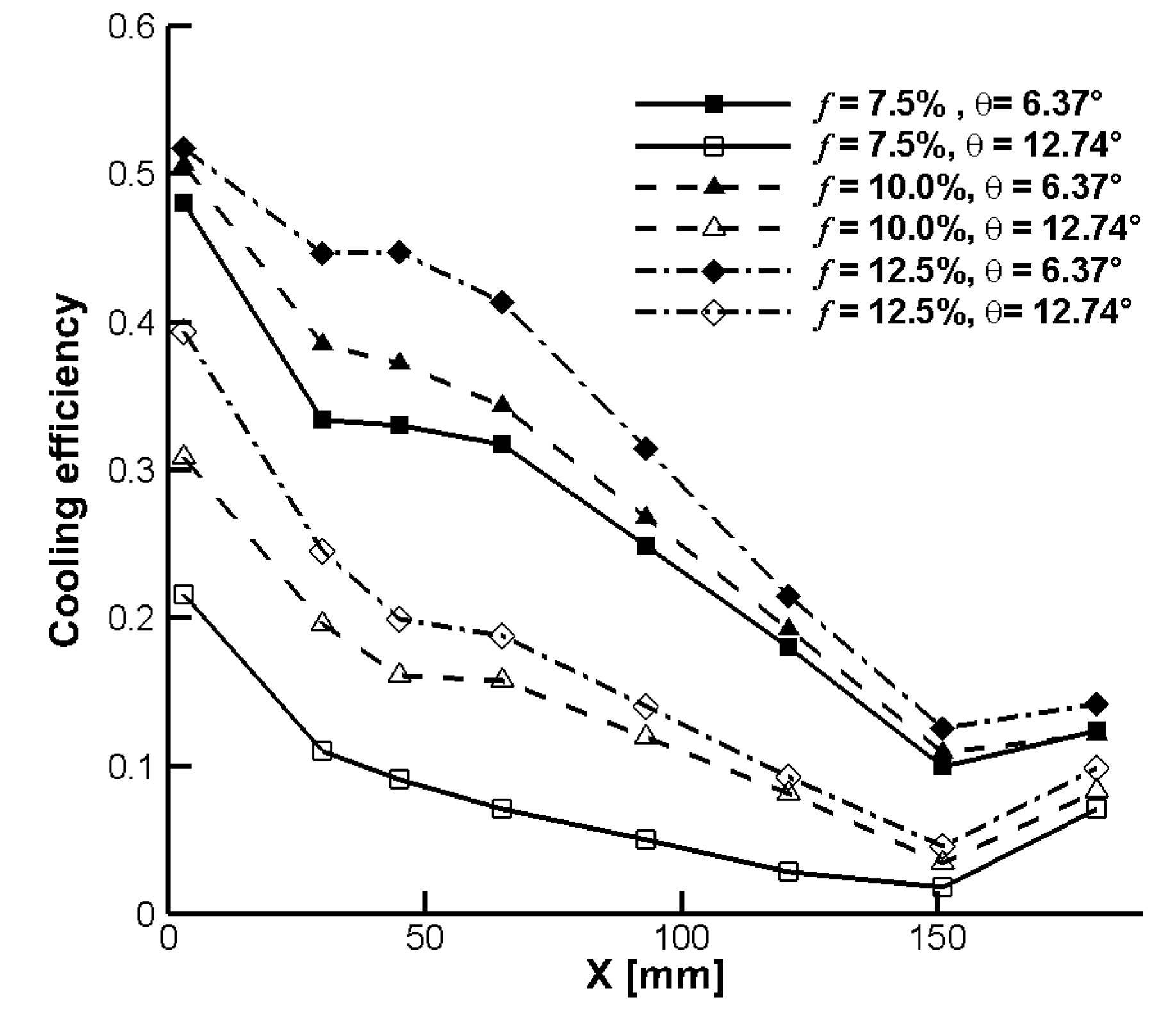
Figure 8 shows the cooling efficiency for different film flow ratio f and slot widths θ when the slot thickness is set to 0.3 mm. It has been noted that for the same f value, doubling the slot width reduces the cooling efficiency by 50%. This phenomenon can be explained as follows:
(1)
When f is constant, and the slot width θ rises, the film medium’s outlet velocity and momentum drop, which does not contribute to cooling stability. Meanwhile, the intensity of convective heat transfer between the coolant and the inner wall diminishes as the coolant velocity falls, thus reducing cooling performance.
(2)
With the increase in the slot width, the contact area between gas film and mainstream increases. Moreover, the mixing phenomenon between these two flows leads to more coolant entering the region away from the inner wall, thereby reducing the cooling capacity. When the slot thickness is small, the mainstream can simply penetrate the gas film near the wall, which results in the mass loss of the coolant.
Aside from the slot width, slot thickness (H) is another key parameter affecting the outlet structure of film orifices near the faceplate region. Figure 9 shows the cooling efficiency distribution for the slot width of θ = 6.37° and different film flow ratio f and H values. It is observed that for a constant film flow ratio, the cooling efficiency increases as the slot thickness H decreases. The slot width directly determines the outlet area of the film orifice, which affects the film outlet velocity and blowing ratio. Accordingly, the film blowing ratio with a constant f increases as the slot width decreases, thereby improving the cooling efficiency. Furthermore, reducing the slot thickness decreases the initial thickness of the film layer, which improves the stability of the layer, weakens the entrainment of the gas film into the mainstream, and improves the cooling effect near the faceplate region.
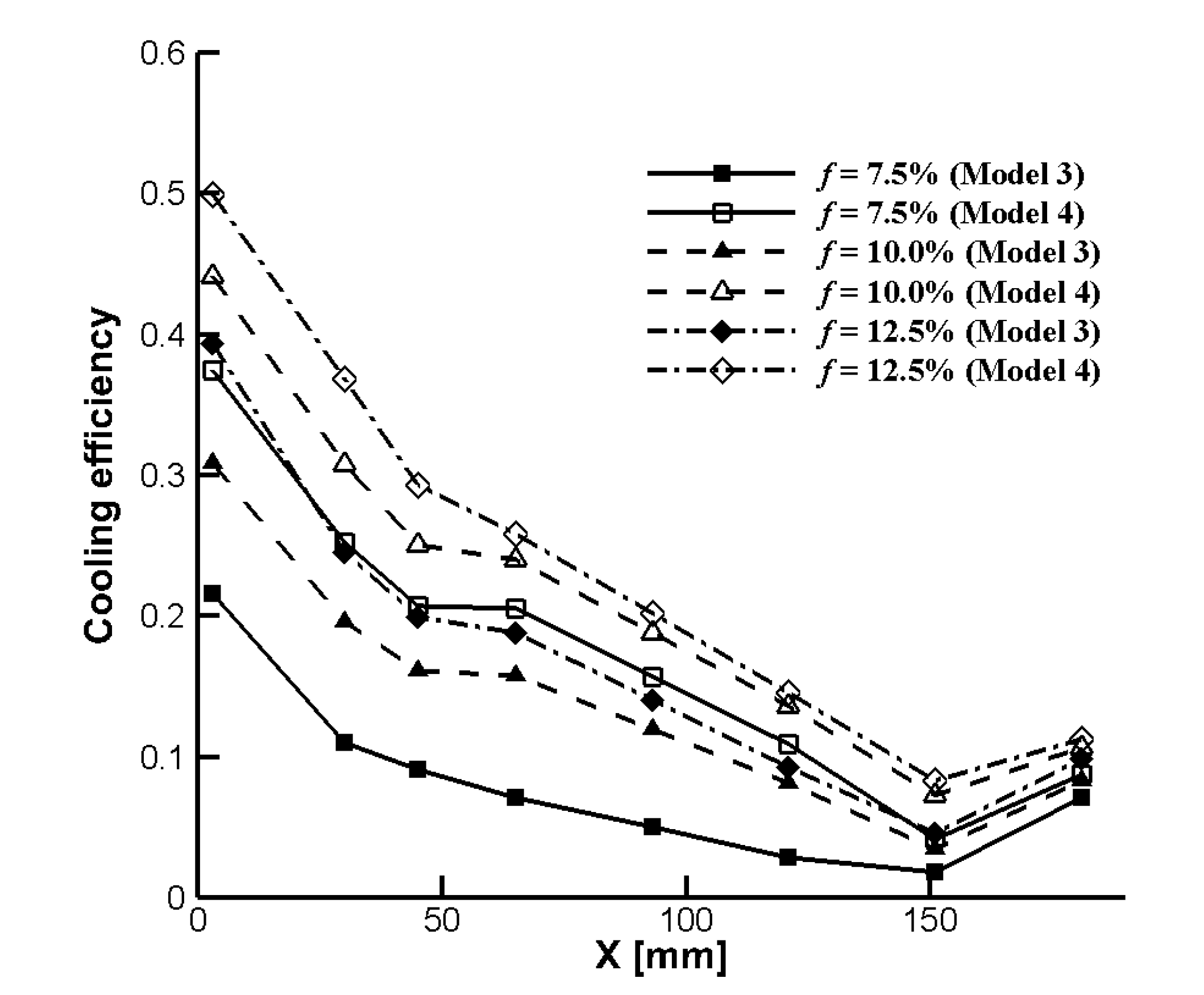
The width and thickness of the slot affect the outlet area of the film orifice, thereby affecting the cooling efficiency. In this regard, the axial distribution of the cooling efficiency with a constant outlet area of film orifices and different values of the f parameter is presented in Figure 10. It is observed that in all cases, the cooling efficiency has a decreasing trend. When f is set to a certain value, the cooling efficiency of Model 4 is 25% higher than that of Model 3. This is more pronounced when f is small. It is found that when the film blowing ratio is constant, reducing the slot width is more effective than the reduction in the slot thickness to improve the cooling efficiency.
As a common structure in the conventional combustion chambers, the cylindrical orifice has been widely studied so far [26]. The hot tests are carried out to investigate the cooling effect of the two structures, and the structural parameters of film orifices are given in Table 5. It should be indicated that Models 6 and 7 have the same film orifice outlet areas to ensure that the two configurations have an equal film blowing ratio. The axial distribution of the film cooling efficiency for Models 6 and 7 is shown in Figure 11., indicating that when f = 7.5%, the cooling effect of discrete-slot film orifices outperforms that of cylindrical orifices in most regions. Moreover, cylindrical orifices have obvious advantages when the value of the f parameter is 12.5%. However, the cooling effect difference between the two configurations is negligible when f = 10.0%. Under this condition, cylindrical orifices have a slight preponderance only downstream of α = 15° and α = 30°. Accordingly, the influence of film flow rate should be taken into account while designing film orifices in the rocket engine.

3.2. Orthogonal Experiment Results

In Figure 12, the heat flux distributions obtained from the numerical simulation and the experimental data are compared. Overall, the simulated data are in reasonable agreement with the experimental results. The simulation results show clearly that the heat flux reaches a peak near the injector region due to the intense expansion of the flame hitting the wall. A difference of approximately 10% between the simulation results and the experimental data is acceptable for engineering applications. Thus, the computation methodology is consequently applicable to the following studies.
The impacts of slot width, thickness, adjacent film orifice area ratio (ef), and film flow ratio on the effectiveness of discrete-slot film cooling near the faceplate region are investigated in the orthogonal experiment. The area ratio of the adjacent film orifice is defined as the outlet area ratio of orifices with α = 30° to α = 0°, which is used to characterize the film orifice layout. The orthogonal experimental design table is presented in Table 6.
To further investigate the discrete-slot film cooling, a numerical simulation is carried out to analyze more parameters, including the combustion length (L90), the maximum temperature of the faceplate (Tm), and circumferential nonuniformity (Km). L90 is used to characterize the combustion performance of the propellant in the thrust chamber. In a H2/O2 rocket engine, L90 is defined as the distance from the faceplate when the mass fraction of H2O reaches 90% of the complete combustion. Moreover, Tm is an important characterization parameter of the thermal environment at the head of the thrust chamber. Studies show that when Tm exceeds a certain threshold, the faceplate is ablated, thereby affecting the reliable operation of the thrust chamber. Meanwhile, Km reflects the bias of the inner wall temperature and can be expressed in the form below:
K m = max K i , i = 1 , 2 , 3 , , n
For an arbitrary axial position, nonuniformity is determined as:
K i = T i , m T i , a v e T i , a v e
where T i , m a x and T i , a v e are maximum and average temperatures in this position circumferential direction, respectively. To express the cooling effect near the faceplate region more intuitively, η 50 was defined as the average cooling efficiency within the range of 0~50 mm from the faceplate.
Figure 13 depicts the range of results as well as the effect of discrete-slot film design factors on average cooling efficiency near the faceplate section. In the selected parameter range, the film flow ratio has the largest impact on η 50 and its affecting degree is much higher than the other three parameters. It has been discovered that as the film flow ratio rises, η 50 rises significantly as well. However, as the other design parameters increase, η 50 reduces and the variation trend with the area ratio of the adjacent film orifice is gentle.
Since the width and thickness of the slot have the same contribution to the outlet area of film orifices, increasing the slot width or thickness separately would linearly increase the outlet area. Subsequently, the film outlet velocity reduces, and the cooling effect weakens. Therefore, the width and thickness of the slot have the same impact on the average cooling efficiency of the head. Increasing the area ratio of the adjacent film orifice equals increasing the overall outflow area of film orifices in the event of a constant film flow ratio. However, the area change originating from the adjacent film orifice area ratio is small compared with the slot width and thickness. Thus, near the injector region, the adjacent film orifice area ratio has little effect on the average cooling efficiency.
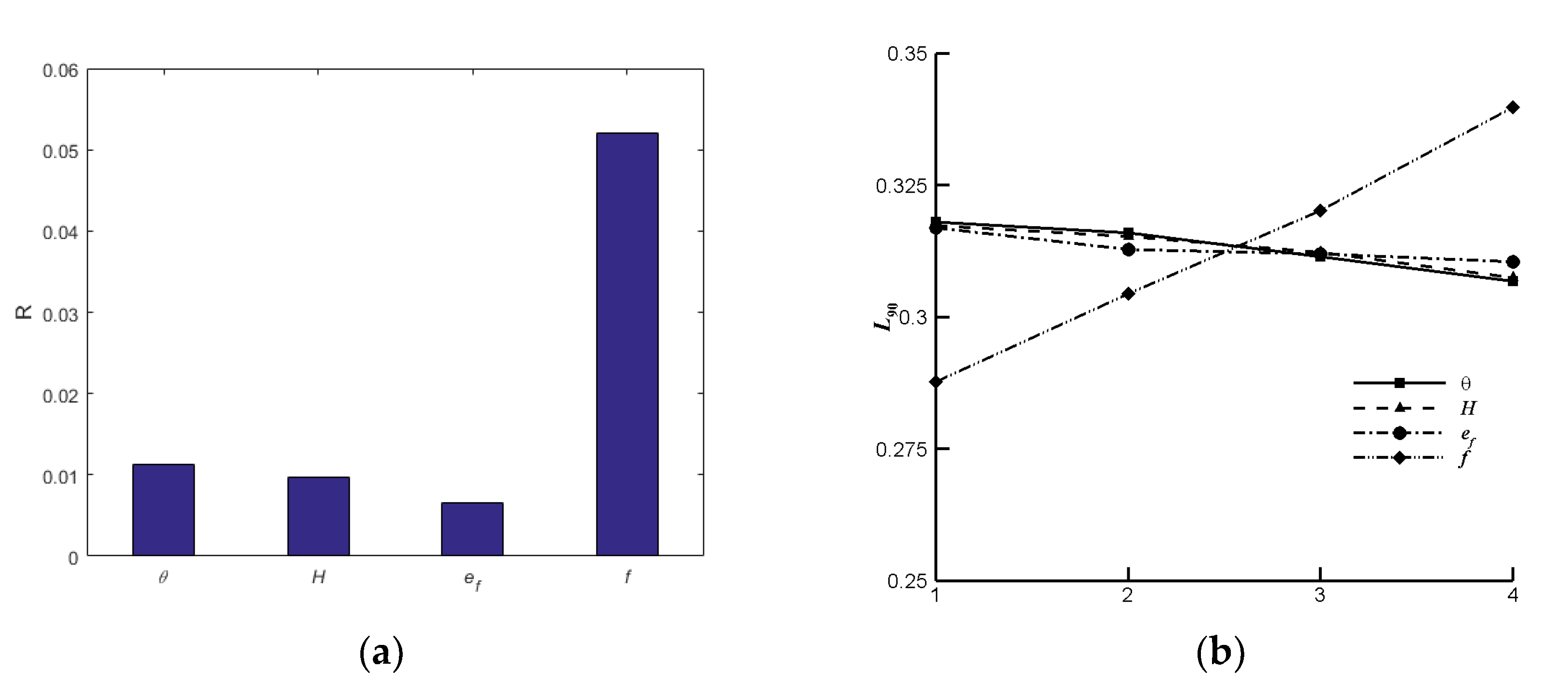
Figure 14 depicts the range of results as well as the effect of various design factors on the combustion length and shows the obtained results from the range and influence of various design parameters on the combustion length. Among the studied parameters, the film flow ratio has the highest impact on L90, followed by the slot width, slot thickness, and the adjacent film orifice area ratio. It is observed that as f increases, the interference of the film medium on the flame structure intensifies, and the flame’s development and propagation velocity slow down, thereby increasing the combustion length. Moreover, the slot width and thickness affect the initial velocity and momentum of the film by changing the outlet area of the film orifice, which ultimately affects the impact strength of the film medium on the flame of the peripheral injectors. Comparing Figure 13 and Figure 14 reveals that various parameters have a similar effect on η 50 and L90. However, larger η 50 and smaller L90 are expected in the thrust chamber design. Therefore, the cooling efficiency and combustion length should be weighed in the selection of design parameters.
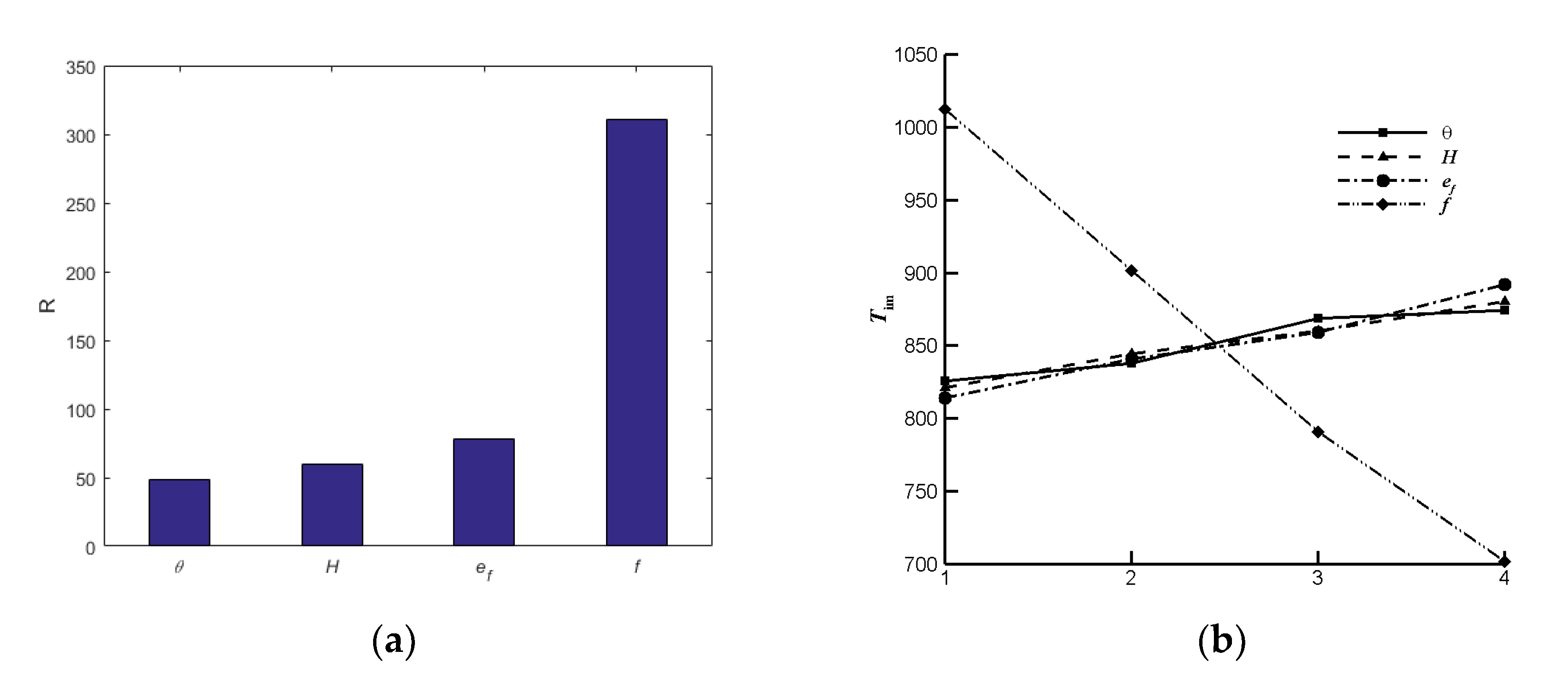
Figure 15 shows the findings of the range and influence of different design factors on the maximum temperature of the faceplate. It is observed that compared with other parameters, the film flow ratio has the highest impact on Tm. The recirculation of the hot gas near the injector region causes part of the coolant to be returned to the faceplate, thereby cooling the faceplate. The film flow ratio is increased, which enhances faceplate cooling while concurrently lowering Tm. The influence of the adjacent film orifice area ratio on Tm is second only to the film flow ratio. Figure 15b indicates that as the adjacent area ratio of the film orifice increase, Tm increases too, indicating that distributing more coolant to the film orifice at α = 0° is an efficient approach to improve the faceplate’s thermal environment.
Figure 16 shows the obtained results from the orthogonal experiment on the circumferential nonuniformity of the inner wall temperature. It is observed that among the studied parameters, the area ratio of the adjacent film orifice has the highest impact on Km. The temperature and heat flux at α = 0° are remarkably higher than that at other positions in the no-film case. The amount of film medium affects the film cooling effect the most, and the inhomogeneous discrete-slot film structure causes the coolant to redistribute in the circumferential direction. For a constant film flow ratio, the amount of coolant distributed at α = 0° decreases as the adjacent area ratio of the film orifice increases. Subsequently, the cooling effect improves in the high thermal load, thereby reducing the circumferential nonuniformity of the inner wall temperature.

4. Conclusions

The impacts of various discrete-slot film cooling design parameters near the faceplate region on the thrust chamber combustion performance and cooling effect were investigated in this study. In the present study, the effects of different design parameters of discrete-slot film cooling in the near-injector region on the performance and cooling effect of the thrust chamber were studied. To this end, experiments and numerical simulations were carried out. The following are the significant achievements and conclusions based on the obtained results:
In the circumferential direction, the cooling efficiency has an M-shaped distribution. As the hot gas combustion and expansion push the coolant to the inner wall, the cooling effect of the region where the injector and film orifice occur simultaneously is greater than that where only film orifices are. In the range of 20~100 mm from the injection faceplate, the film orifices in the middle of the adjacent film orifices have the maximum cooling effectiveness. The cooling efficiency improves as the slot width increases.
Within 120 mm from the faceplate, the cooling efficiency increases significantly as the film flow ratio increases. As the film flow ratio improves, the cooling efficiency increases dramatically within 120 mm of the faceplate. This is especially more pronounced in the range of 30–80 mm from the faceplate. Moreover, the cooling efficiency is found to be proportional to the film flow rate ratio’s 0.4 power. The presented empirical equation is a viable technique to study the cooling efficiency of the combustion chamber under various working conditions within a given range.
Doubling the slot width reduces the cooling efficiency by 50%. Moreover, reducing the slot thickness slows down the decline rate of cooling efficiency near the faceplate region. When the outlet area of the discrete slot is constant, reducing the slot width rather than the slot thickness is more conducive to improving the head cooling efficiency. This is especially more pronounced for small film flow ratios.
The selection of the film orifice shape strongly depends on the film flow ratio. Among the studied cases, the best cooling effect in the condition of small film flow ratio was achieved from the discrete-slot film, and the cylindrical film orifice is more suitable for large film flow ratios.
The findings of orthogonal experiments demonstrate that improving cooling efficiency by raising the film flow ratio and decreasing the slot width and thickness is advantageous., but the influence on the combustion length should be considered. Setting a specific area ratio of the neighboring film orifice can effectively reduce the wall surface temperature circumferential nonuniformity and reduce the temperature of the injection faceplate.

Author Contributions

All authors envisioned the study, participated in its design, and contributed to hot tests and simulations; Conceptualization, X.M., D.L. and T.W. conducted the hot test, collecting and processing data, X.M. and B.S. performed simulations. X. M., D.L., T.W. and B.S. collaborated on the manuscript. All authors have read and agreed to the published version of the manuscript.

Funding

This research was funded by the Chinese National Natural Sciences Fund (U21B2088).

Institutional Review Board Statement

Not applicable.

Informed Consent Statement

Not applicable.

Data Availability Statement

Not applicable.

Acknowledgments

This research did not receive any specific grant from funding agencies in the public, commercial, or not-for-profit sectors.

Conflicts of Interest

The authors declare no conflict of interest.

Nomenclature

DDepth of measurement points, mm
dDiameter, mm
efArea ratio of the adjacent film orifice
fFilm flow rate ratio
HSlot height, mm
KmCircumferential nonuniformity
LDistance between the measurement points and surface, mm
L90Combustion length, m
MBlowing ratio
MROxidant-to-fuel ratio
m ˙ Mass flow rate, g/s
pPressure, Pa
qHeat flux rate m−2
rRadius, mm
RRange
TTemperature, K
xAxial coordinate, mm
α Circumferential degree, ◦
η Cooling efficiency
η c Characteristic velocity efficiency
θ Slot thickness, °
Subscript
aveAverage parameters
cCombustion chamber
effEffective parameters
expExperimental values
filmFilm parameter
gPropellant parameter
HFuel parameter
iSpecies index
inInner surface parameter
mMaximum parameter
no-filmNo-film case parameter
tThroat parameter
OOxidant parameter

References

  1. Zhou, Z.T.; Wang, X.; Lu, C.Y.; Le, G.G. Numerical analysis on thermal environment of liquid rocket with afterburning under different altitudes. Appl. Therm. Eng. 2020, 178, 115584. [Google Scholar] [CrossRef]
  2. Jin, Y.; Xu, X.; Yang, Q.; Zhu, S.H. Numerical investigation of flame appearance and heat flux and in a deep-throttling variable thrust rocket engine. Aerosp. Sci. Technol. 2019, 88, 457–467. [Google Scholar] [CrossRef]
  3. Rasky, D.J.; Pittman, R.B.; Newfield, M.E. The Reusable Launch Vehicle Challenge. In Proceedings of the Space 2006, San Jose, CA, USA, 19–21 September 2006; Technical Report AIAA 2006-7208. American Institute of Aeronautics and Astronautics: Reston, VA, USA, 2008. [Google Scholar]
  4. Lin, J.; West, J.; Williams, R.; Tucker, P.; Chenoweth, J. CFD Code Validation of Wall Heat Fluxes for a GO2/GH2 Single Combustor. In Proceedings of the 41st AIAA/ASME/SAE/ASEE Joint Propulsion Conference, Tuscon, AZ, USA, 10–13 July 2005; Technical Report AIAA 2005-4524. American Institute of Aeronautics and Astronautics: Reston, VA, USA, 2005. [Google Scholar]
  5. Liu, D.; Sun, B.; Wang, T.P.; Song, J.W. Thermo-structural analysis of regenerative cooling thrust chamber cylinder segment based on experimental data. Chin. J. Aeronaut. 2020, 33, 102–115. [Google Scholar] [CrossRef]
  6. Xiang, J.X.; Sun, B.; Wang, T.P.; Yuan, J.Y. Effects of angled film-cooling on cooling performance in a GO2/GH2 subscale thrust chamber. Appl. Therm. Eng. 2020, 165, 114627. [Google Scholar] [CrossRef]
  7. Zhang, G.H.; Liu, J.; Sundén, B. Comparative study on the adiabatic film cooling performances with elliptical or super-elliptical holes of various length-to-width ratios. Int. J. Therm. Sci. 2020, 153, 106360. [Google Scholar] [CrossRef]
  8. Singh, K.; Premachandran, B.; Ravi, M.R. Experimental and numerical studies on film cooling with reverse/backward coolant injection. Int. J. Therm. Sci. 2017, 111, 390–408. [Google Scholar] [CrossRef]
  9. Wei-hua, Y.; Jun, C.; Rui, S.; Xu-sheng, H.; Shuang-wen, S. Experimental investigation on impingement-effusion film-cooling behaviors in curve section. Acta Astronaut. 2011, 68, 1782–1789. [Google Scholar] [CrossRef]
  10. Yang, X.; Hao, Z.H.; Feng, Z.P. An experimental study on turbine vane Leading-Edge film cooling with deposition. Appl. Therm. Eng. 2021, 198, 117447. [Google Scholar] [CrossRef]
  11. Hatch, J.E.; Papell, S.S. Use of a Theoretical Flow Model to Correlate Data for Film Cooling or Heating an Adiabatic Wall by Tangential Injection of Gases of Different Fluid Properties; National Aeronautics and Space Administration: Washington, DC, USA, 1959. [Google Scholar]
  12. Shine, S.R.; Kumar, S.S. Role of Gaseous Film Cooling Injector Orientation in Duct Flow: Experimental Study. Int. Commun. Heat Mass Transf. 2013, 48, 40–45. [Google Scholar] [CrossRef]
  13. Bayraktar, S.; Yılmaz, T. Three-dimensional analysis of temperature field for various parameters affect the film cooling effectiveness. Energy Convers. Manag. 2011, 52, 1914–1929. [Google Scholar] [CrossRef]
  14. Betti, B.; Martelli, E.; Nasuti, F.; Onofri, M. Numerical Study of Heat Transfer in Film Cooled Thrust Chambers. In Proceedings of the 48th AIAA/ASME/SAE/ASEE Joint Propulsion Conference & Exhibit, Atlanta, GA, USA, 30 July–1 August 2012; Technical Report AIAA 2012-3907. American Institute of Aeronautics and Astronautics: Reston, VA, USA, 2012. [Google Scholar]
  15. Liu, Z.G.; Zhang, F.; Liu, Z.; Diao, W.N. An experimental study of the effects of different transverse trenches on deposition on a turbine vane with film-cooling at high temperature. Aerosp. Sci. Technol. 2020, 107, 106340. [Google Scholar] [CrossRef]
  16. Gunady, I.E.; Milani, P.M.; Banko, A.J.; Elkins, C.J.; Katon, J.K. Velocity and concentration field measurements and large eddy simulation of a shaped film cooling hole. Int. J. Heat Fluid Flow 2021, 90, 108837. [Google Scholar] [CrossRef]
  17. Zhao, W.C.; Chi, Z.R.; Zang, S.S. Scaling criteria accuracy for turbine blade film cooling effectiveness at unmatched temperature ratio conditions. Appl. Therm. Eng. 2021, 197, 117363. [Google Scholar] [CrossRef]
  18. Verma, M.; Arya, N.; De, A. Investigation of flow characteristics inside a dual bell nozzle with and without film cooling. Aerosp. Sci. Technol. 2020, 99, 105741. [Google Scholar] [CrossRef]
  19. Kang, H.; Kim, H.; Heo, S.; Jung, S.; Kwon, S. Experimental analysis of hydrogen peroxide film-cooling method for nontoxic hypergolic thruster. Aerosp. Sci. Technol. 2017, 71, 751–762. [Google Scholar] [CrossRef]
  20. Song, J.W.; Sun, B. Coupled heat transfer analysis of thrust chambers with recessed shear coaxial injectors. Acta Astronaut. 2017, 132, 150–160. [Google Scholar] [CrossRef]
  21. Suslov, D.; Arnold, R.; Haidn, O. Investigation of Two Dimensional Thermal Loads in the Region Near the Injector Head of a High Pressure Subscale Combustion Chamber. In Proceedings of the 47th AIAA Aerospace Sciences Meeting including The New Horizons Forum and Aerospace Exposition, Orlando, FL, USA, 5–8 January 2009; Technical Report AIAA 2009-450. American Institute of Aeronautics and Astronautics: Reston, VA, USA, 2009. [Google Scholar]
  22. Negishi, H.; Daimon, Y.; Kawashima, H. Flowfield and Heat Transfer Characteristics in the LE-X Expander Bleed Cycle Combustion Chamber. In Proceedings of the 48th AIAA/ASME/SAE/ASEE Joint Propulsion Conference & Exhibit, Atlanta, GA, USA, 30 July–1 August 2012; Technical Report AIAA 2014-4010. American Institute of Aeronautics and Astronautics: Reston, VA, USA, 2014. [Google Scholar]
  23. Coy, E.B. An Efficient Method for Calculating Surface Temperature and Heat Flux Based on Embedded Temperature Sensors. In Proceedings of the 26th AIAA Aerodynamic Measurement Technology and Ground Testing Conference, Seattle, WA, USA, 13–26 June 2008; Technical Report AIAA 2008-3952. American Institute of Aeronautics and Astronautics: Reston, VA, USA, 2008. [Google Scholar]
  24. Sun, B.; Wang, T.P.; Liu, D.; Xiang, J.X. Method of Heat Flux Measurements Based on Single-Point Temperature Data in Heat-Sink Combustion Chambers. J. Propuls. Technol. 2018, 39, 881–887. [Google Scholar]
  25. Sozer, E.; Vaidyanathan, A.; Segal, C.; Shyy, W. Computational Assessment of Gaseous Reacting Flows in Single Element Injector. In Proceedings of the 47th AIAA Aerospace Sciences Meeting including The New Horizons Forum and Aerospace Exposition, Orlando, FL, USA, 5–8 January 2009; Technical Report AIAA 2009-449. American Institute of Aeronautics and Astronautics: Reston, VA, USA, 2009. [Google Scholar]
  26. Ma, X.Y.; Sun, B.; Wang, T.P.; Liu, D. Experimental investigation of the gas film cooling efficiency of the cylindrical holes near the injector region. Int. J. Therm. Sci. 2021, 165, 106928. [Google Scholar] [CrossRef]
Figure 1. Configuration of the thrust chamber.
Energies 15 03459 g001
Figure 2. Conformation of the film supply section.
Energies 15 03459 g002
Figure 3. Computational domain.
Energies 15 03459 g003
Figure 4. Wall temperatures for various mesh resolutions and y+ for base mesh.
Energies 15 03459 g004
Figure 5. Distribution of cooling efficiency at different slot widths. (a) θ = 6.37°. (b) θ = 12.74°.
Energies 15 03459 g005
Figure 6. Variations of the cooling efficiency along the axis direction (H = 0.3 mm, θ = 6.37°). (a) α = 0°. (b) α = 15°. (c) α = 30°.
Energies 15 03459 g006
Figure 7. Transformed cooling efficiency along the axial direction. (a) α = 0°. (b) α = 15°. (c) α = 30°.
Energies 15 03459 g007
Figure 8. Average cooling efficiency along the axial direction.
Energies 15 03459 g008
Figure 9. Cooling efficiency along the axial direction for θ = 6.37°.
Energies 15 03459 g009
Figure 10. Distribution of the cooling efficiency along the axial direction with a constant outlet area of film orifices.
Energies 15 03459 g010
Figure 11. Comparison of film cooling efficiency in Models 6 and 7. (a) α = 0°. (b) α = 15°. (c) α = 30°.
Energies 15 03459 g011
Figure 12. Heat flux density profile for the simulation and experiment result.
Energies 15 03459 g012
Figure 13. Range and impact of various parameters on η 50 . (a) Range. (b) Influence trend.
Energies 15 03459 g013
Figure 14. Range and impact of various parameters on L90. (a) Range. (b) Influence trend.
Energies 15 03459 g014
Figure 15. Range and influence trend of different parameters on Tm. (a) Range. (b) Influence trend.
Energies 15 03459 g015
Figure 16. Range and influence of different parameters on Km. (a) Range. (b) Influence trend.
Energies 15 03459 g016
Table 1. Geometry parameters of combustion chamber and injectors.
ParameterdcdtdOdHidHo
Value67.825.44.86.87.6
Table 2. Reduced chemistry mechanism [25].
No.Reaction
R1H2 + O2 → 2OH
R2H2 + OH → H2O + H
R32OH → H2O + O
R4H2 + O → OH + O
R5O2 + H → OH + O
R6H + O + M → OH + M
R72O + M → O2 + M
R82H + M → H2 + M
R9OH + H +M → H2O + M
Table 3. Numerical setup boundary conditions.
BoundaryTypeTemperatureSpecific
H2 injectors inletMass flow300 K47 g/s
O2 injectors inletMass flow300 K303 g/s
Film inletMass flow300 K-
OutletPressure outlet-101,325
Injector wall and faceplateNon-slip wall-Adiabatic
Outer wallNon-slip wall-Free convection heat transfer
Symmetric planeSymmetry--
Table 4. Experimental design parameters and key results.
Hθf m ˙ g   MRM η c  
Model 1----0356.35----0.965
Model 20.36.37°7.5358.033.721.380.974
6.37°10.0358.125.011.860.970
6.37°12.5358.126.372.370.968
Model 30.312.74°7.5354.003.741.400.955
12.74°10.0355.755.091.900.960
12.74°12.5356.956.232.320.962
Model 40.66.37°7.5358.783.640.670.957
6.37°10.0357.855.010.930.960
6.37°12.5357.855.991.110.960
Model 50.612.74°7.5353.233.832.890.964
12.74°10.0348.624.893.730.973
12.74°12.5347.436.354.860.967
Table 5. Structural parameters of film orifices.
Orifice ShapeDiameter θ H
Model 6cylindrical1.2--
Model 7discrete slot-6.37 0.3
Table 6. Orthogonal experiment design table.
CaseθHeffCaseθHeff
16.380.301.005.82912.760.300.408.8
26.380.450.808.81012.760.450.605.82
36.380.600.6012.21112.760.600.8015.9
46.380.750.4015.91212.760.751.0012.2
59.570.300.6015.91315.950.300.8012.2
69.570.450.4012.21415.950.451.0015.9
79.570.601.008.81515.950.600.405.82
89.570.750.805.821615.950.750.608.8
Publisher’s Note: MDPI stays neutral with regard to jurisdictional claims in published maps and institutional affiliations.

