Article

Numerical Study on Characteristics of Bedrock and Surface Failure in Mining of Shallow-Buried MCS

1
School of Surveying and Land Information, Henan Polytechnic University, Jiaozuo 454000, China
2
School of Resouce and Civil Engineering, Liaoning Institute of Science and Technology, Benxi 117004, China
*
Authors to whom correspondence should be addressed.
Energies 2022, 15(9), 3446; https://doi.org/10.3390/en15093446
Submission received: 9 April 2022 / Revised: 27 April 2022 / Accepted: 6 May 2022 / Published: 9 May 2022
(This article belongs to the Topic Mining Safety and Sustainability)

Abstract

:
Coal is one of the important energy sources for industry. When it is mined, it will cause the destruction of bedrock and surface. However, it is more severe in mining shallow-buried multi coal seams (SBMCS). To better reveal the characteristics of the bedrock and surface damage, we have carried out a theoretical analysis, as well as used numerical simulations and field monitoring methods to study the surface and bedrock damage caused by the mining of SBMCS. The characteristics of bedrock and surface failure structure, settlement, and stress distribution were studied and analyzed. The findings show that the collapsed block, formed by the rupture of the overlying stratum, interacts with the surrounding rock to form large cavities and gaps, and the stress concentration occurs between them. The maximum downward vertical concentration stress is about 9.79 MPa. The mining of the lower coal seam can lead to repeated failure of the upper bedrock and goaf. The settlement of bedrock presents gradient change, and the settlement of upper bedrock is large, about 8.0 m, and the maximum settlement is 8.183 m, while that of lower bedrock is small and about 3.5–4.0 m. The weak rock stratum in the bedrock is crushed by the change stress of repeated mining, and formed a broken rock stratum. The cracks in the bedrock develop directly to the ground. On the ground, tensile cracks, compression uplift, stepped cracks, and even collapse pits are easy to cause in mining SBMCS. Affected by repeated mining, the variation of surface vertical stress is complex and disorderly in the middle of the basin, and the variation of horizontal stress is mainly concentrated on the edge of the basin. The maximum stress reaches 100 KPa, and the minimum stress is about 78 KPa. Through theoretical analysis and discussion, the size of the key blocks is directly related to the thickness and strength of the rock stratum.

1. Introduction

Coal is a non-renewable fuel energy, which is gradually replaced by renewable energy. However, in today’s world, it is still one of the most important industrial energy sources. Coal resource exploitation still plays a vital role in the energy planning and management of all countries in the world. The safe and efficient mining of coal is related to the national industrial and economic development. After coal mining, the bedrock layer and surface are damaged, affecting and threatening the safety of working face and surface. Coal fields are widely distributed in China, and the occurrence conditions of coal seams are different [1,2]. Qinshui coalfield, in Shanxi Province, is the basin coalfield with the most abundant coal in North China. It belongs to the coal-bearing strata of the Benxi Formation, Taiyuan Formation, and Shanxi formation developed in the late Paleozoic [3,4]. It is a typical geological condition for the occurrence of multiple coal seams. The mining thickness of coal seams in Qinshui coalfield varies greatly. According to [1], coal seam in Benxi Formation is thick in the Northeast and West, and thin in the central and South; coal seam in Taiyuan formation is thick in the East and thin in the West; coal seam in Shanxi formation is the thickest coal bearing group, which is thick in the North, thin in the South, thick in the East, and thin in the West. The geological conditions of shallow burial multi coal seams (SBMCS) refer to the geological conditions in which the coal seams are buried in a shallow depth, the composition and structure of the bedrock are relatively simple, and there are three or more coal seam occurrence geological conditions. The mining of SBMCS is affected by factors such as coal seam depth, coal seam thickness, bedrock and interlayer lithology, geological structure, and fault [5]. Many scholars have conducted in-depth research on multi coal seam (MCS) mining, under different geological mining conditions, from the perspectives of bedrock failure structure characteristics, roof structure characteristics, rock movement law and stability, and fracture development characteristics, and they achieved fruitful research results. Zhang [6], Lin [7] and others studied the characteristics of overburden movement and fracture development, affected by repeated mining in MCS, by using a similar simulation method, and they determined the relationship between fracture development height, overburden lithology, and thickness. The fracture development, rock fracture, and water loss of MCS mining are studied. The stress field distribution of bedrock and surface needs to be further discussed. Qin [8], Dong [9], Yang [10], and others used a combination of various methods to study the structural characteristics of mining MCS and analyzed roof instability and working face pressure, the calculation method of coal mine support resistance and the breaking impact effect of roof structure, and obtained the laws of MCS bedrock failure and roof structure characteristics. Based on the study of coal seam group, the stability and rock failure mechanical characteristics are analyzed. The bedrock and surface damage caused by SBMCS mining need to be further studied. Chen [11], Yan [12], Dong [13], and others studied the surface movement and deformation characteristics, surface dynamic prediction, bedrock damage, and migration law of SBMCS mining by means of numerical simulation, similarity test, and field monitoring. They found the relationship between the surface movement, bedrock damage, and bedrock fracture development of SBMCS and the bedrock buried depth and lithology. Their research on SBMCS is more comprehensive, through on–site monitoring, numerical simulation and theoretical analysis. However, they are aimed at the geological conditions with thick loose layers, and most of the research areas are located in the desert area of Northwest China. According to the geological conditions of Qinshui coalfield, further research is needed. Xie [14] et al. studied the basic roof structure characteristics, movement, and deformation law of MCS mining, providing the basis for the mechanical calculation of bedrock movement and deformation. The equivalent basic roof structure and activity law of overburden between MCS are studied. The mechanical analysis of surface failure and the fracture structure of bedrock in MCS are not studied in detail. Zhao [15] and others used the discrete element UDEC numerical simulation software and mining subsidence prediction software to simulate and study the surface residual settlement after mining, which provided a theoretical feasibility demonstration for coal mining under a high-speed railway. Wu [16] et al. Used FLAC3D to simulate the conditions of different bedrock heights and determined the impact of repeated mining on the height of “two zones”. UDEC is a discrete element method, which can better simulate the characteristics of an overburden collapse zone caused by mining, and it has certain limitations on the simulation of initial stress before mining and the interaction between broken rock and soil. FLAC belongs to the finite element method and adopts the algorithm based on the Lagrange continuity equation. It also has certain limitations in the simulation of collapse and cracking. The above research shows that the mining of SBMCS is a complex problem related to geological conditions. The bedrock and surface failure characteristics and stress distribution law of SBMCS mining, under the geological conditions of Qinshui coalfield, need to be studied further. In numerical simulation, the discreteness of bedrock failure and the continuity of initial stress after mining cannot be well treated by using the finite element or discrete element method, respectively. Discrete element and finite element methods are widely used in geotechnical engineering and underground engineering. Then, before mining, the rock stratum is a continuous medium, and it becomes a discrete block structure after mining. Therefore, a new method of coupling a finite element and discrete element, which is Continuous Discontinuous Element Method (CDEM), can solve this problem [17,18].
This paper attempts to use the CDEM and Generalized Digital Emulation Manu-facturer(GDEM) software numerical simulation platform to study the bedrock failure characteristics, structural form, and bedrock stress distribution characteristics of SBMCS [19]. We take Majiazhuang coal mine in the southeast of Qinshui coalfield as the engineering background. It provides a numerical analysis basis for SBMCS mining in the southeast of Qinshui coalfield, and it provides a theoretical basis for safe mining and green mining of mines with MCS geological conditions. The remainder of this manuscript is organized as follows. In Section 2, Methodology, we mainly expound the mechanical analysis of key blocks and CDEM algorithm. In Section 3, Materials and Methods, we mainly describe the engineering background of the engineering research area, modeling, and simulation process. In Section 4, Results, we analyzed the failure characteristics of bedrock, surface stress distribution, and settlement, according to the results of numerical simulation and field monitoring. In Section 5, Discussion, we obtain bedrock failure characteristics and processes, and we discuss the impact of water on mining and the CDEM numerical simulation method. In Section 6, Conclusions, we describe the research results for the research content, as well as the conclusions obtained.

2. Methodology

2.1. The Calculation of Key Stratum Failure

After the coal seam is mined, the key layer in the rock stratum can support the overlying rock. However, the key layer will collapse when it reaches the ultimate bearing capacity [20]. The key block structure is formed after collapse, which interacts with the rock stratum and floor to form a stable structure. According to relevant literature research [21], it is found that, after the coal seam is mined, the key block plays a very important role. It forms a relatively stable structure to support the rock mass on it. We need to establish a mechanical model to deeply study and discuss the process.
Mechanical analysis shall be carried out from the initial stage of key block collapse. With the continuous advancement of the working face, the direct roof of the upper coal seam reaches the limit span, resulting in separation and collapse [22]. The key stratum bears the upper bedrock load. When the key stratum reaches the ultimate bearing capacity, cracking and disconnection will occur at both ends, as well as midspan of the rock beam, in the key stratum [23]. Under the action of friction and extrusion force between key blocks, the blocks produce rotary motion and finally reach a static equilibrium state, as shown in Figure 1.
After bedrock collapse, the key blocks interact with the coal seam floor and surrounding rock to form a relatively stable structure. According to the “masonry beam” theory [24,25], there is a height difference between the horizontal thrusts TA and TB on both sides, and the compressive stress passes through the overhanging fault block to form the rear arch. The compression force TC in the fault block increases with the increase in the overhanging area of the block, where the two blocks are squeezed and broken, and the friction force of the block decreases. When the friction force between the two blocks is less than the shear force on the contact surface, the broken block slides down and sinks along the contact surface, resulting in rotational deformation and instability. The key stratum fractured for the first time, and the formed key block constituted an asymmetric three–hinge arch structure [26,27].
As for the geometry in Figure 1, assuming that the rotation angle of the key block is β, the subsidence amount is w, the length of the key block is equal to L, the upper part of the block is uniformly distributed with load q, and the generated horizontal thrusts are TA and TB, it functions with points A and B. The thickness of the block is hm, point A is subjected to frictional force RA, and point B is subjected to a supporting force qB of upward distance d. Point C is the hinge point of the fractured block, which transmits the internal force TC between the two block systems. It is a force per unit length (1 m).
According to the overall equilibrium state of the two key block structures, the equilibrium equation can be obtained:
F = 0 M = 0
where F is the force in different directions, N;
M is the moment generated by each force, N·m;
According to the force analysis of the key blocks, as shown in Figure 1 and Formula (1), TC can be calculated that:
T C = q L ( L cos β + h m sin β ) 2 ( h m cos β w )
where TC is the internal force between the two blocks, N/m;
q is the load above the block, MPa;
β is the tilting rotation angle of the block, °;
hm is the height of the block rock beam, m;
W is the subsidence caused by block rotation, m.
According to the geometric relationship, as shown in Figure 1, we can be known that
sin β = w L cos β = L 2 w 2 L
Substituting Formula (3) into Formula (2), the relationship between thrust TC and settlement w can be calculated:
T C = q L 2 L 2 w 2 + h m L w h m L L 2 w 2 w
In the initial stage of key stratum failure, when periodic failure occurs, the rotation angle β is usually small, and the ratio of rock layer thickness to failure distance (hm/L) is usually small and can be ignored in the calculation process. We can get:
L 2 w 2 L h m L ( 1 50 ~ 1 20 )
Therefore, Formula (4) can be approximately simplified to
T C = q L 2 L h m w
According to the relevant knowledge of mechanics, rock beam collapse is usually caused by tensile failure in the middle, so the relationship between the initial collapse distance Lini and the tensile strength of rock stratum σmax can be calculated as follows [11,24].
L i n i = h m σ max q
where Lini is the initial collapse distance of bedrock, m;
q is the load applied on the collapse block, Mpa;
σmax is the maximum tensile strength of broken block, Mpa.
From the above analysis, it can be concluded that the size of the key blocks is directly related to the thickness and strength of the rock stratum, as well as the load on the bedrock.
The failure of key stratum has a direct relationship with the properties of the rock formation, and the failure distance to reach the initial failure can be calculated, as shown in Formula (7). Therefore, the horizontal thrust TC can be expressed by the tensile strength of the rock stratum σmax, and the relationship between hm and L can be obtained.
T C = 1 2 h m 2 h m w σ max
The large tensile strength and thickness of bedrock make the thrust TC between blocks larger. Therefore, the friction between collapses is large, and it is not easy to slip. When the horizontal thrust reaches the limit, the indirect contact surface of the blocks is broken, resulting in slip and collapse. This also shows that the length and thickness of the collapsed block, as well as the tensile strength of the block itself, affect the size of the space under it and even the duration of the cavity.

2.2. CDEM Algorithm

Before coal mining, each rock mass layer and coal seam are considered to be rock layers with continuous properties. When the coal seam is mined, it first causes the separation and collapse of the direct roof, and then, with the advance of the working face, the basic roof separation and collapse form a discrete block structure. After the coal seam is mined out, the bedrock fractures are developed, which shows the discreteness of cracking. The collapsed blocks fall into the goaf to form a discrete block structure. Therefore, the CDEM, based on the Lagrange equation, should be selected as the numerical simulation method of coal mining. This method can not only calculate the deformation state of coal and rock mass but also simulate the plasticity, damage, and the fracture process of coal and rock mass after applying the Mohr Coulomb criterion of brittle fracture on the virtual contact surface.
CDEM algorithm is an algorithm for solving the explicit solution of the dynamic equation of fractured elements, according to the theory of the generalized Lagrange system [17,18]. The algorithm is based on the strict generalized Lagrange equation, as shown in Formula (9), combined with the global dynamic relaxation algorithm, to iteratively solve the explicit solution of the equation.
d d t ( L x i ) + ( L y i ) = Q i
where xi, yi are generalized coordinates;
L is the energy of the Lagrangian system;
Qi is the work done by non-conservative force.
The basic structure of the CDEM algorithm is composed of two parts: blocks and interface. The block element is usually composed of quadrangles. It has only elastic deformation and no plastic deformation. The plastic deformation is concentrated on the virtual crack. For the direction of crack development and actual cracking, the theoretical direction is perpendicular to the direction of the maximum principal stress of the surrounding element, while the actual direction is the closest element boundary or along a diagonal direction [23]. Interface element is a constitutive model describing the relationship between adjacent blocks in the block discrete element, also known as contact surface. Three attributes, connecting two block elements and the normal vector of the contact surface, are used to represent the force between block elements. CDEM algorithm is the same grid shared by the Lagrangian element algorithm and the discrete element algorithm.
The core calculation formula of CDEM is shown in Formula (10) [28]:
M u ¨ ( t ) + C u ˙ ( t ) + K u ( t ) = Q ( t )
where M is quality matrix;
u ¨ ( t ) is acceleration matrix;
C is damping matrix;
u ˙ ( t ) is velocity matrix;
K is stiffness matrix;
u ( t ) is displacement matrix;
When the cell is not embedded before the medium cracks, the node only contains unbalanced force (only elastic force and external force); when the medium is cracked or embedded, the node force changes, and the corresponding parameters of node velocity and acceleration motion state are generated. CDEM algorithm couples continuous and discontinuous media algorithms, and it realizes the perfect unity of the finite element, block discrete element, and particle discrete element [29]. GDEM numerical simulation platform, developed based on CDEM algorithm, is independently developed by the Institute of mechanics, Chinese Academy of Sciences. It is a constitutive model based on CDEM method. By means of CPU/GPU and behavior acceleration, it can not only simulate the elastic, plastic, damage, and fracture processes of geological bodies and artificial materials under multi field coupling but also develop unit constitutive and contact constitutive by using C++ or JavaScript, according to actual needs. The platform software contains 14 built-in block constitutive models and 12 built-in interface constitutive models [19]. In this study, the elastic damage fracture constitutive model is adopted, and the mechanical parameters of rock stratum include density, elastic modulus, Poisson’s ratio, tensile strength, and internal friction angle. The brittle damage fracture constitutive model is applied on the virtual interface, and the mechanical parameters of the interface include normal stiffness, tangential stiffness, cohesion, internal friction angle, and tensile strength [30].

3. Materials and Methods

3.1. Geological and Mining Conditions

The study area is located in the southeast of Qinshui coalfield and the east of Jincheng mining area, belonging to the edge of Qinshui Basin. Qinshui coalfield has simple geological structure conditions, a flat coal seam dip angle, multi coal seam occurrence, and strong regularity, and most of the hydrogeological conditions are not complex. The geological conditions of the mine are the most superior mining conditions in China. Geographical location of the study area is shown in Figure 2.
The coal bearing strata of coal mines in this area are the Permian Shanxi Formation and Carboniferous Taiyuan formation, with a total of 13–15 layers of coal, with a total thickness of nearly 13 m. According to the analysis of the geological data of Majiazhuang coal mine, the stratigraphic structure is mainly sandstone and mudstone, including limestone and siltstone. There are three stable minable coal seams, of which the buried depth of 3# coal seam is 31.4 m, and the average coal thickness is 2.9 m; the buried depth of 9# coal seam is 84.6 m, and the average coal thickness is 1.0 m; the burial depth of 15# coal seam is 120.4 m, and the average coal thickness is 4.3 m. Other coal seams are unstable coal seams or coal lines, which are not minable or are partially minable. The coal seam dip angle of the mine is less than 3°, which is a nearly horizontal coal seam, belonging to the typical SBMCS occurrence condition on the southeast boundary of Qinshui coalfield, as shown in Figure 3.

3.2. Model and Mechanical Parameters

This simulation takes the geological conditions in the southeast of Qinshui coalfield as the background, and it establishes a 1:1 numerical simulation model. A 2D model of 35 coal and rock strata is designed, including seven groups of rock strata with different properties and three coal seams. The design dimension of the model is 127.5 m high and 600 m wide. The mining length of the simulated working face is 300 m. The mining thickness is designed according to the actual average mining thickness of each layer of coal. According to the boundary conditions of the model, the left and right boundaries are fixed by means of zero velocity in the X-axis direction; in the Y-axis direction, the bottom boundary is completely fixed, and the upper boundary is free, as shown in Figure 4.
The initial in-situ stress of this simulation is calculated by using the linear elastic constitutive model, and the unbalance rate is set to 1 × 10⁻⁵. The mechanical parameters required for calculation are shown in Table 1.

3.3. Simulation Scheme and Steps

This time simulates the mining process of three stable and minable coal layers in the southeast of Qinshui coalfield, studies the characteristics of bedrock failure and surface movement, and analyzes the characteristics of bedrock stress distribution. The numerical calculation is divided into two stages and three times of coal seam excavation. In the initial geostress calculation stage, the virtual mass calculation method is adopted. During the simulation, the coal and rock strata are discretized as a whole. The strength and stiffness of the contact surface are inherited from the cell strength, and the strength of the contact surface is set as 10% of the cell strength to obtain the initial geostress state under the action of gravity. The initial strain of coal is converted into the constitutive model of brittle rock after the initial strain of the coal-softening element is converted into the constitutive model of brittle rock. In the stage of the coal seam excavation solution, in order to better simulate the bedrock breaking process, the displacement and change gradient within the calculation range are zeroed. Then, calculate the coal seam excavation stage, excavate in three times, and set it as “None” model, according to the designed coordinate range of coal seam goaf, to realize coal seam excavation. After each coal seam excavation, the solution time step is set to 10,000. In order to master the variation law of surface settlement, monitoring points with an interval of 10 m are set on the surface. When simulating the excavation of different coal seams, the characteristics of bedrock fracture and surface failure are recorded.
The numerical model is corrected and adjusted by using surface monitoring data. During 3# coal mining, surface safety monitoring was conducted, and monitoring points were arranged along the advancing direction of the working face to monitor surface settlement.

4. Results

4.1. Analysis of Bedrock Failure Characteristics

This simulation adopts a 2D plane model. After the excavation calculation of three layers of coal, the failure characteristics of bedrock are obtained, as shown in Figure 5. Figure 5a shows that, when mining the upper coal seam, the coal seam floor near the coal pillar at the edge of the goaf is uplifted, and the floor is cracked and damaged. The key bedrock layer above the edge of the goaf breaks down to form a key block structure. The inclined broken block contacts the coal seam floor and the upper rock mass to form a triangular suspended space. The key blocks in the middle of the goaf are unstable and broken, and the “masonry beam” structure is formed by stacking in the goaf [19]. Affected by the failure of bedrock, there are the tensile zone, compression zone, and compressive uplift zone on the surface.
With the mining of the middle coal seam, the floor uplift of the upper coal seam gradually disappears. The mining thickness of the middle coal seam is small, and the change of bedrock failure characteristics is not obvious. Figure 5 shows the bedrock failure characteristics after mining of the lower coal seam. When the lower coal seam is mined, the coal seam floor is broken and lifted. The failure of the lower direct roof rock layer develops upward and affects the goaf and bedrock of the middle and upper coal seams, resulting in its instability and fracture again, and the floor rock layer of the middle coal seam breaks down, which makes the key rock layer above the middle coal seam unstable and collapse. A key block structure is formed at the edge of the goaf to support the overlying strata. The rock stratum breaks and collapses, and the cracks of the bedrock develop directly to the surface, resulting in great damage to the surface, forming huge staggered platforms, cracks, or collapse pits, with large widths and depths of damage. The development of fissures connects the goaf and the surface of the three layers of coal, resulting in the discharge of harmful gases. At the same time, it also forms a water diversion channel, and the water and sediment are fed into the working face and goaf. This not only pollutes the air and water near the mining area but also threatens the safety of the working face and surface water.
According to the analysis of Figure 5c, the stress change of bedrock has obvious characteristics, and the failure of rock stratum starts from the surface of rock stratum. The bedrock above the edge of the goaf is mainly broken, cracked, and with tensile damage, while the middle part is mainly compressive and shear damage. The weak rock stratum in the bedrock is damaged by shear and tension, and the broken rock stratum belt is formed under the action of repeated mining. The damage boundary in bedrock decreases suddenly with the increase in mining depth. The damage boundary line presents a parabola shape and is symmetrically distributed on both sides of the goaf. The content shown in Figure 5d is the cloud map of bedrock settlement, and the bedrock settlement shows three gradients with the change of depth. The settlement of the lower bedrock is only affected by the mining of 15# coal seam, and the settlement is small, about 3.5–4.0 m; the subsidence of the middle bedrock is larger than that of the lower bedrock. Affected by the mining of the middle and lower coal seams, the subsidence caused by the bedrock has a superposition effect, and the subsidence is about 4.88–5.5 m; the upper bedrock has the largest settlement, which is affected by the mining of all coal seams, and the cumulative effect is more obvious. The maximum settlement is 8.183 m. From the gradient settlement caused by bedrock failure, the bedrock settlement caused by MCS mining is related to the mining thickness of the coal seam, and the influence is cumulative. The mining of the lower coal seam will lead to the repeated destruction of the rock mass of the upper bedrock and goaf, and the subsidence of the bedrock and surface bedrock, caused by the mining of the lower coal seam, is the most severe.

4.2. Bedrock Failure Stress Analysis

The stress balance of bedrock is broken during coal mining, resulting in bedrock instability, fracture, and fragmentation. After all the coal is mined, the stress distribution nephogram of bedrock failure shows left-right symmetry. The horizontal stress and vertical stress are selected for comparative analysis. It can be seen from Figure 6 that the left part is the cloud diagram of vertical stress distribution, and the right part is the cloud diagram of horizontal stress distribution. Before the instability and collapse of the key bedrock layer, it exists in the form of “cantilever beam” and suddenly breaks after reaching the ultimate bearing capacity. The key block is subjected to the pressure of the upper rock mass, and the vertical stress concentration occurs in the rock stratum above the coal pillar. The maximum downward vertical stress is about 9.79 MPa, and the maximum upward vertical stress is about 2.73 MPa. At the same time, the coal pillar is also affected by vertical stress, resulting in bending deformation and even coal explosion and rock explosion accidents. Before the bedrock is broken, it is stretched and bent, and there is a horizontal stress concentration area in the upper part of each rock stratum. After the rock stratum is broken, the stress on the upper and lower sides of the key block changes: the upper part is subjected to compressive stress, the lower part is subjected to tensile stress, and then, there is a horizontal stress concentration area. In the broken rock stratum, the interaction between rock blocks also produces stress concentration points. After the bedrock is broken, the maximum horizontal stress value is 4.9–6.1 MPa, which is symmetrically distributed left and right, in the opposite direction, and points to the middle of the basin.

4.3. Surface Deformation and Stress Characteristics

There is a tensile zone, a compression zone, and a compressive fracture zone in the surface basin. The tensile zone is located at the edge of the surface subsidence basin, and the surface fractures are relatively developed, resulting in step fractures and tensile fractures [31]. The compression zone is located at the bottom of the edge of the subsidence basin, the cracks are closed, and the topsoil is compressed without crushing damage. The compression and fracture area is in the middle of the surface basin [32]. The topsoil is in the state of compression and fracture, resulting in compression and shear failure, and compression uplift occurs in some areas. These surface damage phenomena are consistent with the characteristics of surface damage caused by SBMCS [31,33].
In order to better analyze the characteristics of surface movement and deformation, in the process of numerical simulation, a monitoring point is set every 10 m on the surface, and a total of 61 surface monitoring points are arranged to monitor the settlement value and stress distribution of the surface during the simulation process, as shown in Figure 7. The characteristics of surface subsidence accord with the law of surface subsidence in the actual mining process. The surface presents a flat bottom moving basin, and the characteristics of surface subsidence caused by MCS mining are also obvious. According to Figure 7a, the three dense areas of the curve in the middle of the basin show the maximum subsidence curves of the three coal seam excavation stages, respectively. According to the 3# coal surface monitoring data collected, the maximum settlement is 2.622 m, and the maximum settlement obtained by numerical simulation is 3.0 m. The simulation state is ideal, and the difference of settlement is 0.378 m, which is a reasonable range. According to Figure 7b, the distribution law of surface horizontal stress is that the stress concentration fluctuates up and down at 10 KPa (downward), the stress in the middle of the basin (within 200~400 m) changes frequently, complexly, disorderly, and greatly, the stress value changes greatly, and the difference between the maximum value and the minimum value is greater than 26 KPa; however, the stress changes at the edge and outside of the basin are small [34].
According to Figure 7c, the overall variation characteristics of surface horizontal stress are obvious. Near the edge of the mobile basin (within 100 m), the horizontal stress changes significantly, and the horizontal stress changes slightly in the middle and outside of the mobile basin. The maximum stress reaches 100 KPa, and the minimum stress is about 77 KPa. Therefore, within a certain range of the surface, at the edge of the goaf, the horizontal stress changes actively, and the phenomena of tension and compression are obvious. The opening and closing movement of surface cracks in this area is obvious. Combined with the change of vertical stress, it is easy to produce staggered cracks and surface uplift. The stress change has obvious stratification phenomenon. The mining activity of the lower coal seam has an impact on the upper goaf and its bedrock. The stress increases due to the influence of lower coal seam mining.

5. Discussion

5.1. The Bedrock Failure Process and Characteristics of MCS

After each layer of coal is mined, a caving zone is formed. Then, the roof collapses directly, forming a collapse zone. The rock blocks falling into the goaf are relatively broken, and the particle size is small, which is mainly affected by the impact force of the mining. The volume of the broken rock and soil mass of the roof becomes larger, due to the influence of rock formation fragmentation. In the bedrock between different coal seams, when the key stratum reaches the failure limit, it presents a cantilever beam structure to support the broken rock layer above [20,35]. As the working face advances, a sudden brittle fracture occurs when the cantilever beam exceeds the ultimate bearing capacity. As the height increases, the filling space becomes narrow, and after the key layer above breaks down, an ordered block structure is formed as shown in Figure 8. The blocks are discrete and stacked on each other to form a masonry beam structure [12,36]. Therefore, the settlement of the broken bedrock layer, composed of the collapse zone and “masonry beam”, needs many years to be gradually compacted, and the surface of the goaf can reach a relatively stable state. The bedrock damage caused by MCS mining is more serious than that caused by single seam mining, and the damage recovery time may be longer.
The mining of SBMCS causes the damage state of bedrock and surface, which is directly related to the mining geological conditions. In Northwest China, the coal seam is thicker, and the bedrock is thinner. The surface of many coal mines is covered with thick loose aeolian sand layer, and the bedrock is thin [11,30]. The destruction of bedrock and surface caused by mining is more serious. However, the loose layer can repair the surface damage automatically and slowly. There are few buildings on the surface, which is suitable for mechanized high-intensity mining [37]. There are many differences between the multi coal seam mining in the Qinshui coalfield and the MCS mining in the Shendong mining area. Qinshui Coalfield does not have a thick loose layer on the surface, but it has thinner Loess and Sand Gravel. Therefore, the self-healing ability of the surface is poor. As a result, the failure characteristics and stress field distribution of the bedrock are different.

5.2. Impact of Water on Mining Safety

Underground mining engineering is a very dangerous thing if it is under the city or underwater. The water body has a great impact on the mining of coal mine. The mining causes the destruction of bedrock, and the crack is a good channel for the water body, which poses a great threat to the mining face. The mining of shallowly buried multi coal seams leads to bedrock collapse and relatively developed fractures, which leads to the direct connection between the surface and the working face and forms a water diversion channel. Surface water, groundwater, underground phreatic water, and other water bodies are affected by bedrock fissures and feed into the mining face, resulting in a flood in the working face.
The interaction between water body and coal rock mass is a complex physical and chemical process. Chemical actions such as dissolution, hydration, dissolution, and oxidation-reduction may occur between the water body and coal rock mass, which will not only change the composition and structure of coal rock mass but also affect the mechanical properties of coal rock mass [38] The infiltration of water into the rock and soil will also change its physical properties. The water in the fractured rock mass will produce lubrication at the fracture contact surface, reduce the friction resistance at the fracture surface, enhance the shear stress effect, and induce the shear movement along the fracture surface. Under the action of water softening and argillization, the filler in the fracture surface of rock mass begins to develop from solid state to plastic state to liquid state with the increase in water content, which reduces the mechanical properties of fractured rock mass, cohesion, and friction angle [39]. At the same time, the surface water is fed into the goaf, so that a large number of water bodies are stored in the goaf and overburden fractures, and the harmful substances in the goaf will also pollute the water bodies. For the research on the influence of overburden on water, it is necessary to establish water monitoring (water level monitoring, water quality monitoring, pore water pressure monitoring) and relevant tests of various rock masses under different saturated water conditions. The research on the coupling effect of water body and rock mass needs further research.

5.3. Numerical Simulation Method

In terms of numerical simulation, the CDEM algorithm has many advantages in the process. The GDEM platform can organically combine the finite element and discrete element, and it has a good effect on the numerical simulation of bedrock and surface damage in coal mining. UEC software, based on the discrete element, and FLAC software, based on the finite element, can simulate and analyze underground mining. However, compared with the GDEM platform, based on the CDEM method, the GDEM platform is closer to engineering practice, has more constitutive models, and the mining process can be redeveloped. If there is a water-resisting layer in the goaf geological conditions, corresponding measures shall be taken to protect the water resisting layer. In mining MCS, attention should be paid to controlling the development height of bedrock fractures and keeping the water resisting layer from being damaged. We can regard the aquifer as an elastic template, build a balanced differential equation according to the theory of elastic mechanics and elastic foundation, and solve the differential equation, according to the relevant boundary conditions in the mining process. Furthermore, the mechanical analysis and calculation of multiple water barriers can be realized.

6. Conclusions

Through the research of this paper, it is found that the bedrock and surface damage caused by coal mining have strong regional characteristics. Different geological conditions have different characteristics. Bedrock damage and fracture development, caused by SBMCS mining, have regional characteristics. Different lithology, different water conditions, different burial depths, mining thickness conditions, and method of mining are all important factors affecting the failure characteristics of overlying rocks. The conclusions of this paper are as follows:
(1)
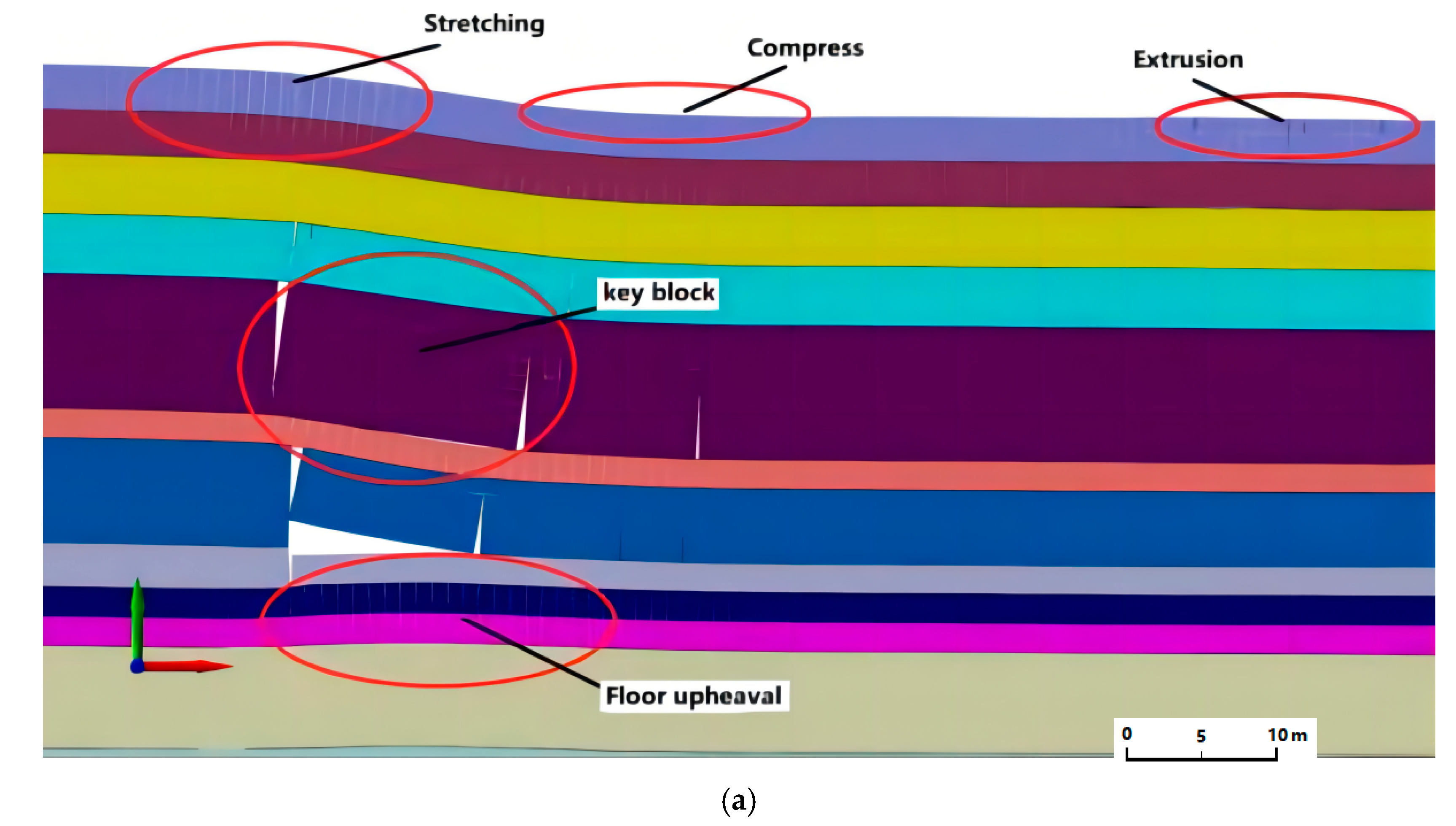
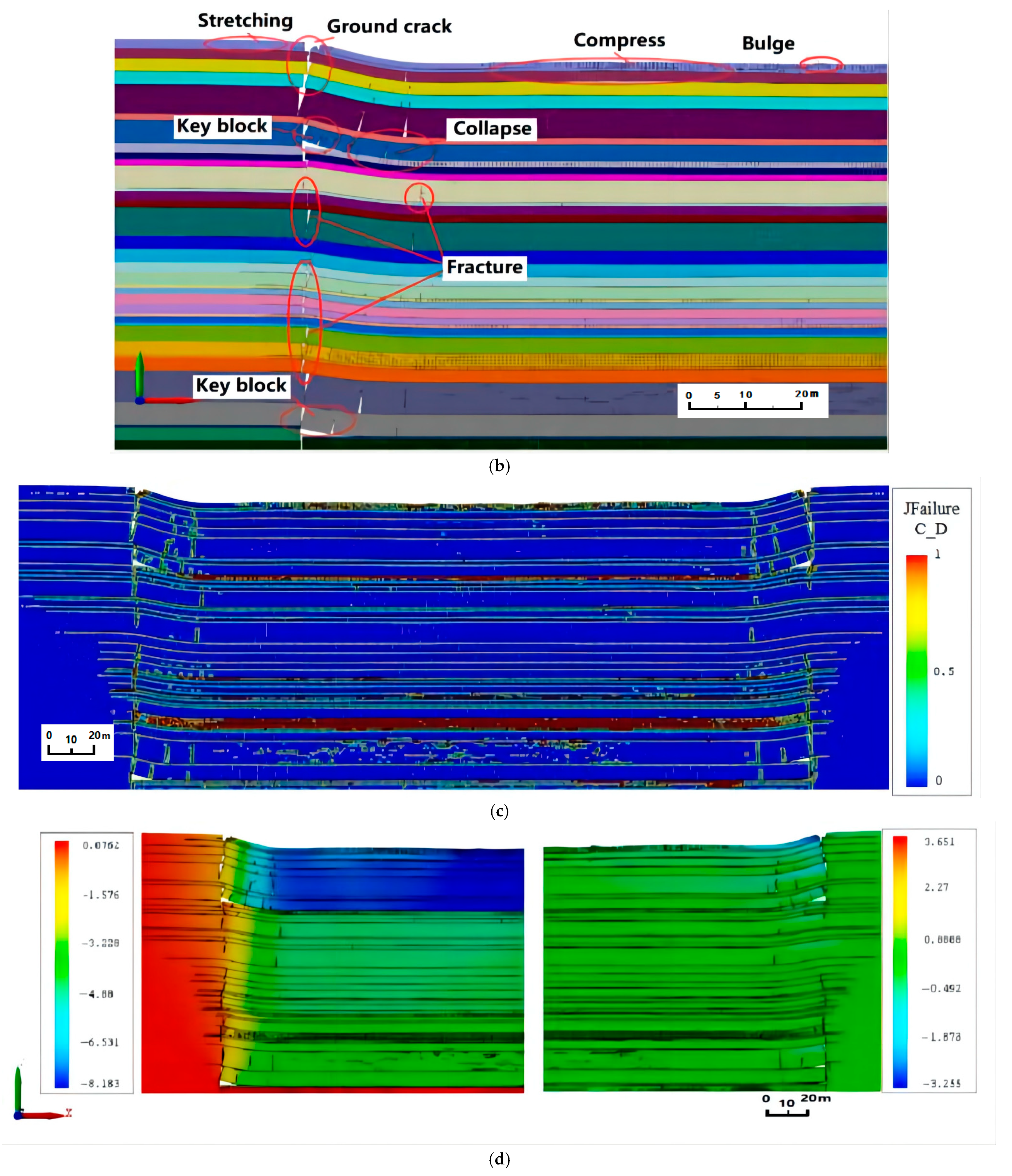
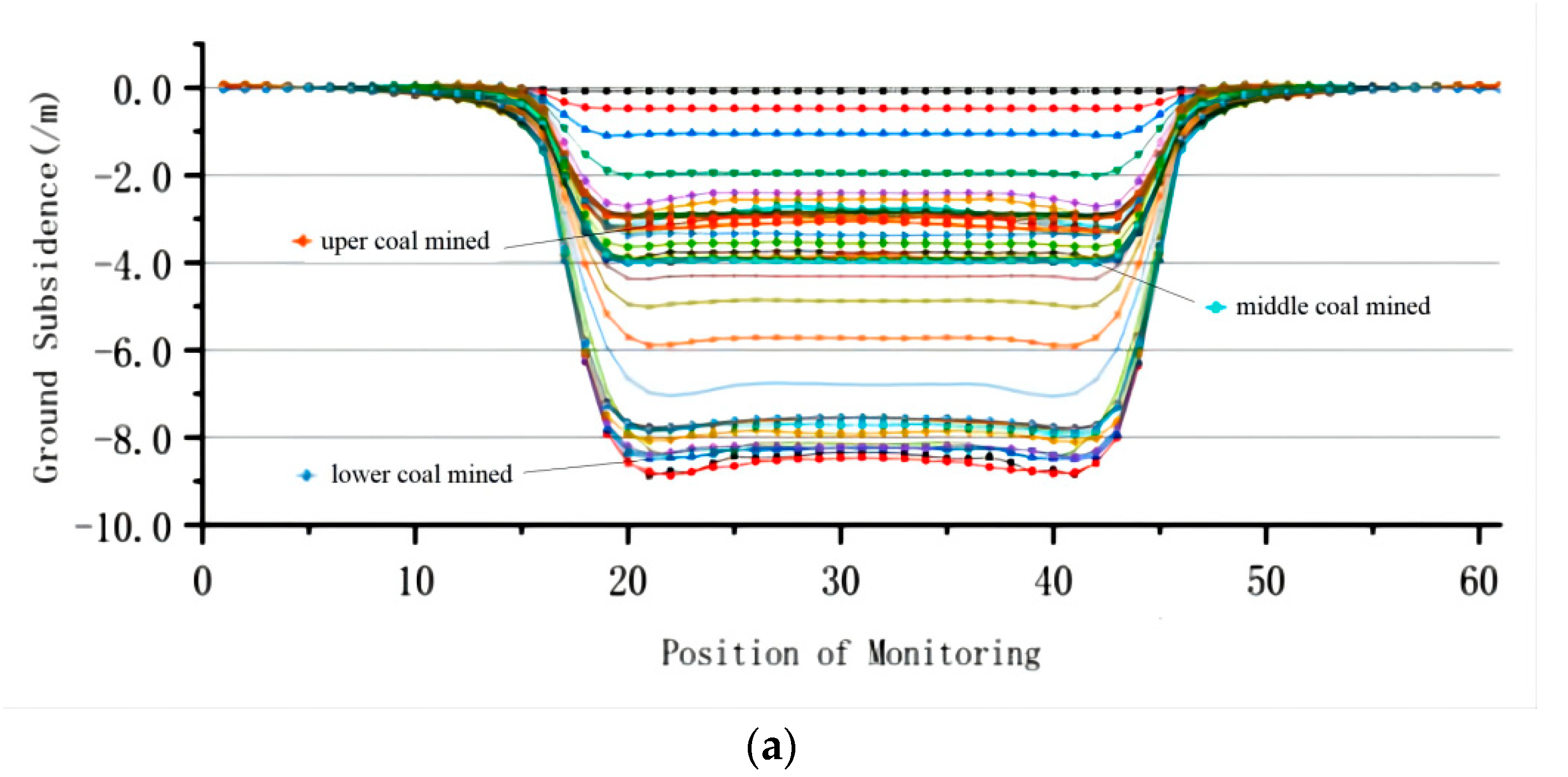
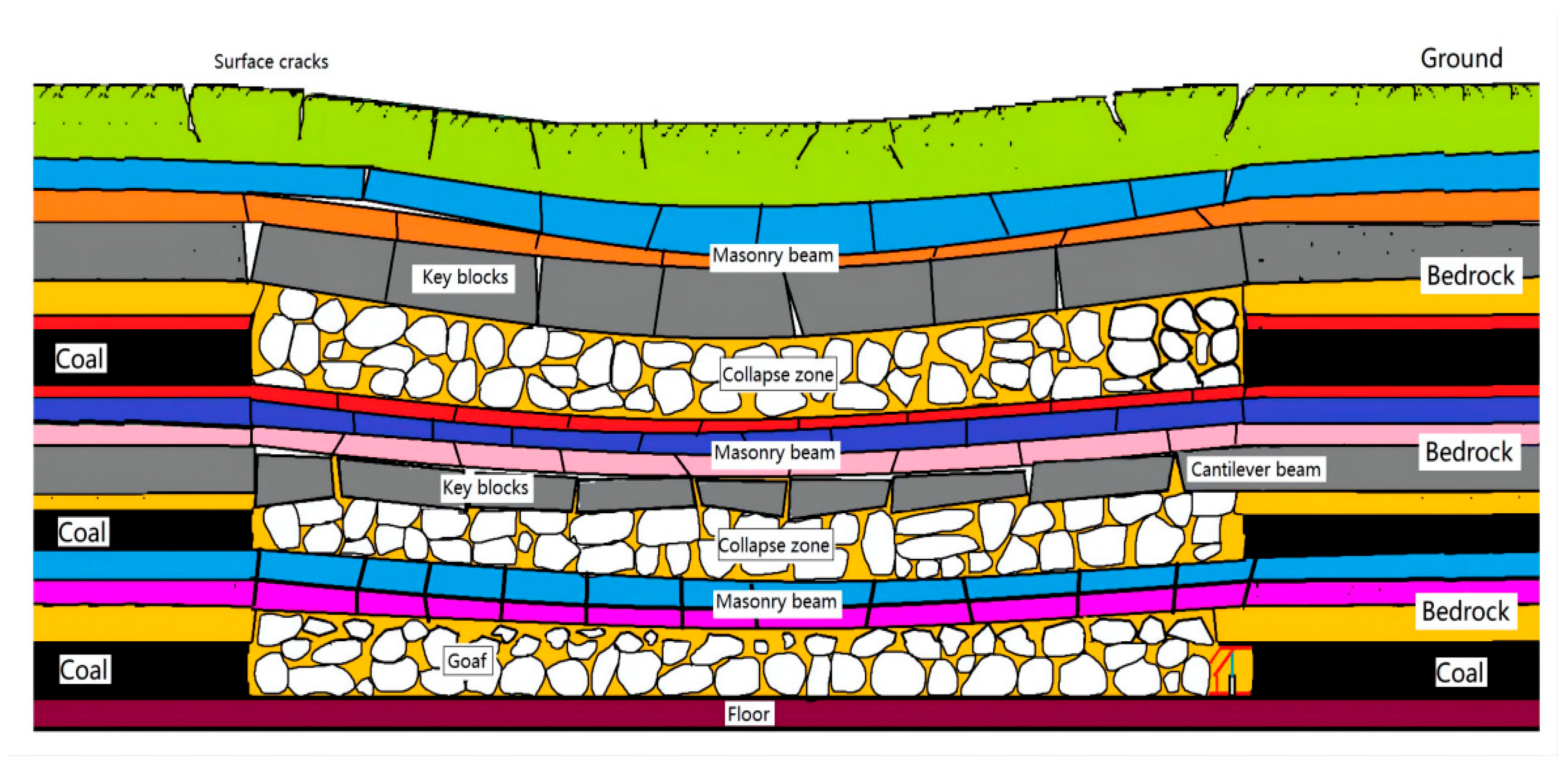
Affected by the repeated mining SBMCS, the bedrock is seriously damaged, and the bedrock is broken above the edge of the goaf, forming collapse pits, step cracks, and other failure forms. The weak rock stratum in the bedrock is affected by repeated mining to form a broken rock stratum belt. Repeated mining leads to a gradient change of bedrock subsidence. The settlement of mining 15# coal seam, and the settlement of bedrock between 15# coal and 9# coal is small, about 3.5–4.0 m, while the maximum settlement is 8.183 m on the ground.
(2)
After the bedrock breaks, it forms a broken block, which overlaps with the coal seam floor and surrounding rock to form a large suspended space. The size of the key blocks is directly related to the thickness and strength of the rock stratum, as well as the load on it. After discussion and analysis, the horizontal thrust between the collapsed blocks of the overlying rock is related to the tensile strength and thickness of the overlying rock. The cracks in the bedrock are relatively developed. The mining of the lower coal seam leads to a large number of pores and cracks in the upper bedrock and the collapsed rock mass in the goaf. The crack is connected with the surface, which makes it easy to form sand and water burst accidents.
(3)
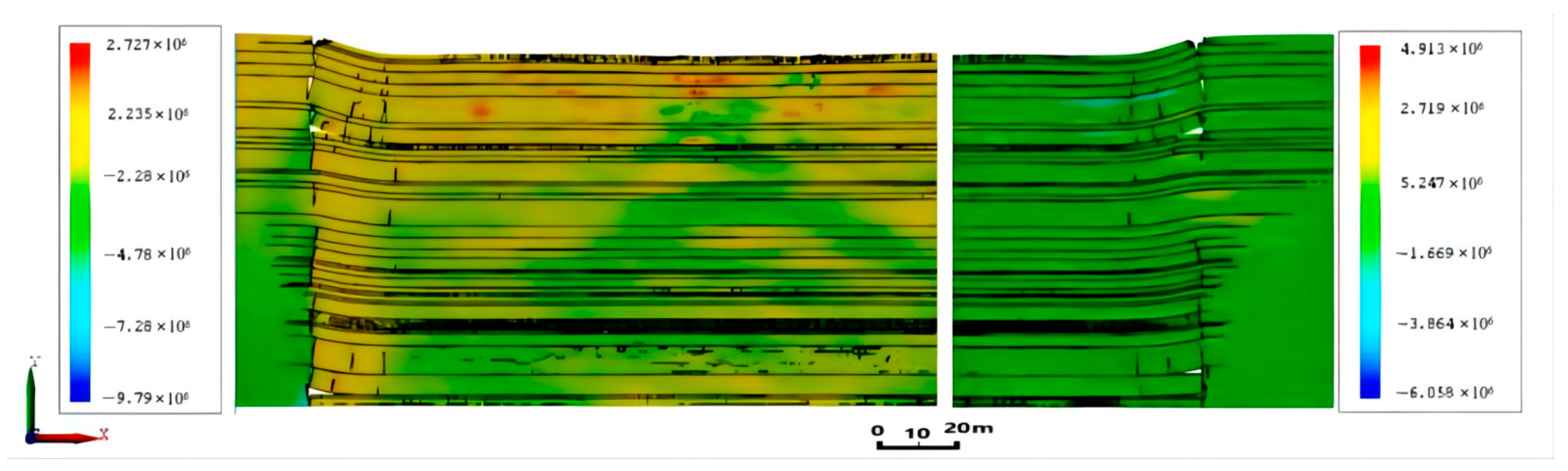
The surface damage caused by SBMCS mining is more serious and complex. The amount of surface subsidence has the superposition effect of surface subsidence caused by repeated mining of MCS. The horizontal stress changes significantly along the edge of the surface subsidence basin, which is prone to tensile and compressive failure. The central part of the mobile basin is affected by repeated mining and presents complex vertical stress changes. The maximum stress reaches 100 KPa, and the minimum stress is about 77 KPa.
(4)
The CDEM algorithm has many advantages in the process of numerical simulation. The GDEM platform can organically combine a finite element and a discrete element, and it has a good effect on the numerical simulation of bedrock damage in coal mining. In this study, it is necessary to further study and analyze the coupling effect between water body and bedrock. The coupling mechanical model of water body and broken rock mass is established to study the influence of the coupling model on the stress and settlement of bedrock and surface.

Author Contributions

Conceptualization, Y.Z. and H.C.; methodology, G.L.; software, G.L. and W.Z.; validation, Y.X., H.C. and G.L.; formal analysis, Y.Z.; investigation, W.Z.; resources, G.L.; data curation, G.L.; writing—original draft preparation, G.L.; writing—review and editing, Y.Z.; visualization, G.L.; supervision, W.Z.; project administration, W.Z.; funding acquisition, Y.Z. and W.Z. All authors have read and agreed to the published version of the manuscript.

Funding

This research was funded by the National Natural Science Foundation of China, grant number U1810203 and U21A20108, and This research was funded by Henan province science and technology tackling key project, China, grant number 212102310404. And This research was supported by the Fundamental Research Funds for the Universities of Henan Province, China, grant number NSFRF220432.

Institutional Review Board Statement

Not applicable.

Informed Consent Statement

Not applicable.

Data Availability Statement

The data used to support the findings of this study are included within the article.

Conflicts of Interest

The authors declare no conflict of interest.

References

  1. Li, B.; Wang, X.; Liu, Z.; Li, T. Study on multi-field catastrophe evolution laws of water inrush from concealed karst cave in roadway excavation: A case of Jiyuan coal mine. Geomat. Nat. Hazards Risk 2021, 12, 222–243. [Google Scholar] [CrossRef]
  2. Dong, L.; Tong, X.; Ma, J. Quantitative Investigation of Tomographic Effects in Abnormal Regions of Complex Structures. Engineering 2020, 7, 1011–1022. [Google Scholar] [CrossRef]
  3. Liu, G.; Zou, Y.; Zhang, W.; Chen, J. Characteristics of Overburden and Ground Failure in Mining of Shallow Buried Thick Coal Seams under Thick Aeolian Sand. Sustainability 2022, 14, 4028. [Google Scholar] [CrossRef]
  4. Xu, Z.; Liu, Q.; Zheng, Q.; Cheng, H.; Wu, Y. Isotopic composition and content of coalbed methane production gases and waters in karstic collapse column area, Qinshui Coalfield, China. J. Geochem. Explor. 2016, 165, 94–101. [Google Scholar] [CrossRef]
  5. Zhang, Z.X.; Zhang, Y.B.; Zhao, Z.H.; Zhang, L.M. Similar simulation experimental study on overburden movement and surface deformation law in multi coal seam mining. Hydro Eng. Geo 2011, 38, 130–134. [Google Scholar]
  6. Lin, Z.Y. Study on Coalfield Structure and Structural Coal Control in Coal Bearing Area of North China; China University of Mining and Technology: Beijing, China, 2021. [Google Scholar]
  7. Ma, L.; Jin, Z.; Liang, J.; Sun, H.; Zhang, D.; Li, P. Simulation of water resource loss in short–distance coal seams disturbed by repeated mining. Environ. Earth Sci. 2015, 74, 5653–5662. [Google Scholar] [CrossRef]
  8. Qin, Y. Research on Rock Movement Law in Multi Coal Seam Mining; China University of Geosciences: Beijing, China, 2021. [Google Scholar] [CrossRef]
  9. Dong, C. Research on Overlying Rock and Surface Movement and Deformation under Repeated Mining; Taiyuan University of Technology: Taiyuan, China, 2020. [Google Scholar] [CrossRef]
  10. Li, Z.C.; Li, L.C.; Wang, S.R.; Ma, S.; Zhang, Z.L.; Li, A.S.; Huang, B.; Zhang, L.Y.; Wang, Z.L.; Zhang, Q.S. Formation of X-shaped hydraulic fractures in deep thick glutenite reservoirs: A case study in Bohai Bay Basin, East China. J. Cent. South Univ. 2021, 28, 2814–2829. [Google Scholar] [CrossRef]
  11. Chen, J.J.; Nan, H.; Yan, W.T.; Guo, W.B.; Zou, Y.F. Dynamic surface movement and deformation characteristics of shallow buried deep high–intensity mining. Coal Sci. Technol. 2016, 44, 158–162. [Google Scholar]
  12. Yan, W.T.; Chen, J.J.; Chai, H.B.; Yan, S.G. Dynamic prediction model of surface damage in high–intensity mining area. J. Agric. Eng. 2019, 35, 267–273. [Google Scholar]
  13. Dong, L.; Chen, Y.; Sun, D.; Zhang, Y. Implications for rock instability precursors and principal stress direction from rock acoustic experiments. Int. J. Min. Sci. Technol. 2021, 31, 789–798. [Google Scholar] [CrossRef]
  14. Xie, S.R.; Pan, H.; Chen, D.D.; Gao, M.M.; He, S.S.; Song, B.H. Equivalent basic roof structure between layers and its activity law in multi coal seam mining. J. China Univ. Min. Technol. 2017, 46, 1218–1225. [Google Scholar]
  15. Zhao, X.L.; Wang, Y.Q.; Gao, G.Q.; Wu, Y. Safety analysis of coal mining pavement under expressway based on UDEC and settlement prediction. Coal Technol. 2020, 39, 123–127. [Google Scholar]
  16. Wu, Y.L.; Yu, Z.R.; Yan, Z.H.; Zhu, S.Y. Numerical simulation of development characteristics of “two zones” of repeated mining in the first mining face of shallow mining area. Coal Mine Saf. 2019, 50, 199–203. [Google Scholar]
  17. Feng, C.; Li, S.H.; Liu, X.H.; Zhang, Y.N. A semi–spring and semi–edge combined contact model in CDEM and its application to analysis of Jiweishan landslide. J. Rock Mech. Geotech. Eng. 2014, 6, 26–35. [Google Scholar] [CrossRef] [Green Version]
  18. Gao, H.; Feng, C.; Zhu, X.; Zhang, Y.; Wang, X.; Xin, X.; Shen, Y.; Sun, Z. Three dimensional analysis of coal seam gas fracturing mining based on continuous discontinuous element. J. Shandong Univ. 2021, 6, 119–128. Available online: https://kns.cnki.net/kcms/detail/37.1391.T.20210906.0941.010.html (accessed on 6 September 2021).
  19. Beijing Jidao Chengran Technology Co. Operation Manual of Block Dynamics Analysis Software GDEM Blockdyna (v1.0); Beijing Jidao Chengran Technology Co., Ltd.: Beijing, China, 2021. [Google Scholar]
  20. Qian, M.; Miao, X.; Xu, J. Theoretical study on key stratum in strata control. J. China Coal Soc. 1996, 21, 12–23. [Google Scholar]
  21. Xu, J.; Qian, M. Method for identifying the location of key overburden layers. J. China Univ. Min. Technol. 2000, 29, 463–467. [Google Scholar]
  22. Li, S.H.; Wang, J.G.; Liu, B.S.; Dong, D.P. Analysis of criticalexcavation depth for a jointed rock slope using a face-to-face discrete element method. Rock Mech. Rock Eng. 2007, 40, 331–348. [Google Scholar] [CrossRef]
  23. Ma, C.C.; Chen, K.Z.; Li, T.B.; Zeng, J.; Ma, J.J. Numerical simulation of stress structure rockburst based on GDEM. Tunn. Undergr. Eng. Disaster Prev. 2020, 2, 85–94. [Google Scholar]
  24. Hou, Z.J. Discussion on “short masonry beam”, “stepped rock beam” structure and masonry beam theory in shallow coal seam. J. Coal 2008, 11, 1201–1204. [Google Scholar]
  25. Zhang, J.P. Study on Development Law and Prediction Method of Overburden Fractures in Coal Seam Mining in Shendong Mining Area; Henan Polytechnic University: Henan, China, 2017. [Google Scholar]
  26. Zhao, Y.; Zhou, C.; Zhang, X.; Yuan, C. The pressure arching effect and distribution characteristics offractured strata of single key layer under shallow buried condition. J. China Coal Soc. 2020, 45, 1–11. [Google Scholar] [CrossRef]
  27. Sawamura, Y.; Ishihara, H.; Otani, Y.; Kishida, K.; Kimura, M. Deformation behavior and acting earth pressure of three-hinge precast arch culvert in construction process. Undergr. Space 2019, 4, 251–260. [Google Scholar] [CrossRef]
  28. Wang, D.; Guo, F.; Jia, L.; Xu, X. Three–dimensional stability analysis of soft rock slope along the slope of CDEM open–pit coal mine. J. Saf. Environ. 2021, 21, 195–200. [Google Scholar] [CrossRef]
  29. Wang, X.B. Study on the Coupling Continuous Discontinuous Method of Lagrangian Element and Discrete Element; Science Press: Beijing, China, 2021. [Google Scholar]
  30. Ju, J.; Xu, J.; Zhu, W. Longwall chock sudden closure incident below coal pillar of adjacent upper mined coal seam under shallow cover in the Shendong coalfield. Int. J. Rock Mech. Min. Sci. 2015, 77, 192–201. [Google Scholar] [CrossRef]
  31. Deguchi, T.; Kato, M.; Akcin, H.; Kutoglu, H.S. Monitoring of Mining Induced Land Subsidence Using L– and C–band SAR Interferometry. In Proceedings of the IEEE International Geoscience and Remote Sensing Symposium 2007, Barcelona, Spain, 23–28 July 2007; pp. 2122–2125. [Google Scholar] [CrossRef]
  32. Li, G.; Peng, S.; He, B.; Peng, X.; Yuan, C.; Hu, C. Detection of Coalbed Fractures with P–wave Azimuthal AVO in 3–D Seismic Exploration. Chin. Sci. Bull. 2005, 50, 146–150. [Google Scholar] [CrossRef]
  33. Cross, T.A. Stratigraphic controls on reservoir attributes in continental strata. Earth Sci. Front. 2000, 7, 322–350. [Google Scholar]
  34. Ahmad, A.; Kourosh, S. Prediction of surface subsidence due to inclined coal seam mining using profile function (Prediction of surface subsidence due to inclined coal seam mining using profile function). J. Sci. Technol. 2005, 16, 9–18. [Google Scholar]
  35. He, M.; Zhu, G.; Guo, Z. Longwall mining “cutting cantilever beam theory” and 110 mining method in China—The third mining science innovation. Chin. J. Rock Mech. Geotech. Eng. Engl. Ed. 2015, 5, 10. [Google Scholar] [CrossRef] [Green Version]
  36. Wang, A.; Wang, J. Study on Underground Pressure Law of Large Mining Height Fully Mechanized Face in Soft Rock Shallow Coal Seam. Sci. Technol. Datong Coal Min. Adm. 2016, 4, 20–24. [Google Scholar]
  37. Zou, Y. Evolution Mechanism and Regulation of Surface Ecological Environment under High Intensity Mining; Science Press: Beijing, China, 2019. [Google Scholar]
  38. Guo, H.; Ji, M.; Chen, K.; Zhang, Z.; Zhang, Y.; Zhang, M. The Feasibility of Mining Under a Water Body Based on a Fuzzy Neural Network. Mine Water Environ. 2018, 37, 703–712. [Google Scholar] [CrossRef]
  39. Li, Y.; Zhou, H.; Zhu, W.; Li, S.; Liu, J. Numerical Study on Crack Propagation in Brittle Jointed Rock Mass Influenced by Fracture Water Pressure. Materials 2015, 8, 3364–3376. [Google Scholar] [CrossRef] [Green Version]
Figure 1. Force analysis of the basic structure of the key stratum failure.
Energies 15 03446 g001
Figure 2. Geographical location of the study area.
Energies 15 03446 g002
Figure 3. Comprehensive geological histogram of Majiazhuang mine.
Energies 15 03446 g003
Figure 4. Schematic of model size and boundary conditions.
Energies 15 03446 g004
Figure 5. Characteristics of bedrock and surface damage. (a) Bedrock failure in upper coal seam mining; (b) Bedrock failure of all coal mining; (c) Cloud map of stress distribution of bedrock; (d) Cloud map of bedrock settlement (left is vertical, right is horizontal).
Energies 15 03446 g005aEnergies 15 03446 g005b
Figure 6. Cloud map bedrock stress distribution (left is vertical, right is horizontal).
Energies 15 03446 g006
Figure 7. Characteristic analysis curve of surface movement and deformation. (a) Surface subsidence characteristic curve; (b) Characteristic of surface vertical stress distribution curve; (c) Characteristic of surface horizontal stress distribution curve.
Energies 15 03446 g007aEnergies 15 03446 g007b
Figure 8. Schematic of bedrock failure in mining of MCS.
Energies 15 03446 g008
Table 1. Calculation parameters of rock mechanics.
LITHOLOGYρ (/Kg/m3)E (/GPa)μc (/MPa)σt (/MPa)φ (/°)
Loess and Sand Gravel19000.0150.300.020.6017.0
Mudstone22001.310.242.163.7325.0
Sandstone and Mudstone24402.230.253.804.2530.0
Sandstone26403.540.255.504.7835.0
Limestone28002.660.236.207.9835.0
Sandy Mudstone26130.900.265.504.7830.0
Siltstone25403.160.352.651.3631.0
Coal14001.000.291.251.6025.0
Publisher’s Note: MDPI stays neutral with regard to jurisdictional claims in published maps and institutional affiliations.

