Abstract
To ensure the high-quality output performance of the five-phase fault-tolerant permanent magnet synchronous motor (FTPMSM) drive system under normal and open-circuit faults and achieve the minimal reconfiguration of the FTPMSM control drive system under various open-circuit faults, in this paper, a fault-tolerant field-oriented control (FOC) strategy based on disturbance adaption is proposed. The speed-loop and current-loop steady-healthy controllers are designed to effectively suppress the torque ripples caused by open-circuit faults and improve the robustness of the drive system to load disturbance and motor parameter variation under fault operation. Moreover, the additional zero-sequence current controller can be omitted. In addition, the modified reduced-order coordinate transformation matrices are proposed to weaken the influence of oscillating neutral. Finally, the fault-tolerant FOC system of the FTPMSM is established, and its experiment is conducted. The experimental results verify the feasibility and effectiveness of the proposed control strategy.
1. Introduction
Owing to the advantages of high efficiency, high power density, and wide speed range, a permanent magnet synchronous motor (PMSM) is favored for industrial applications [1]. Compared with the traditional three-phase PMSM, the five-phase fault-tolerant PMSM (FTPMSM) owns the merits of reduced power per phase, lower torque ripples, and better fault-tolerant capacity, which has received innovative research and rapid development in high-reliability applications such as aviation actuators, electric vehicle drive systems, and ship propulsion systems [2,3].
Open-circuit fault is one of the most common motor system faults. To achieve high-performance fault-tolerant operation, it is necessary to use appropriate fault-tolerant control (FTC) strategies for maintaining the output torque [4]. Compared with the existing basic control methods of direct torque control (DTC) [5] and model predictive control (MPC) [6], the vector control algorithm is simple and easy to be implemented. Additionally, it can maintain the advantages of good dynamic and steady-state performance. Thus, fault-tolerant vector control has been widely concerned. The goal of FTC is to minimize the reconfiguration of the drive system under fault-tolerant operation and to ensure good output performance under normal and fault-tolerant operation [7]. The fault-tolerant vector control strategy based on current control has the advantage of being simple and easy to implement [8]. Nevertheless, this kind of FTC strategy exists the problems of unfixed inverter switching frequency, high phase current harmonic content, and low voltage utilization, which is not an ideal motor drive scheme. These problems of hysteresis control can be effectively solved by space vector pulse width modulation (SVPWM) control, and the SVPWM-based FTC strategy was conceived [9]. However, for the SVPWM-based FTC scheme under different fault conditions, its voltage vector needs to be reconstructed, which will increase the complexity of the algorithm. Consequently, the FTC scheme based on field-oriented control (FOC) has attracted much attention [10].
The key to the FOC-based FTC strategy is to construct the reduced-order transformation matrix and derive the mathematical model in the synchronous coordinate system. By using the reduced-order matrix, the online calculation of fault currents in the rotating coordinate system can be achieved [11]. However, in this proposed transformation matrix, the vector space decoupling cannot be realized; thus, the motor’s control performance was affected. In [12], according to the fault-tolerant current reference, the reduced-order Clark and Park transformation matrix was constructed for a five-phase PMSM’s FOC system. Nevertheless, the proposed coordinate matrix is only suitable for these PMSMs with constant inductance and PM flux amplitude. Then, a universal reduced-order matrix for a five-phase PMSM under single-phase fault was constructed in [13], which can effectively improve the dynamic and steady-state performance under fault conditions. In these above FOC-based FTC schemes, the coordinate transformation matrices under fault conditions were reconstructed to maintain the electromagnetic torque. Additionally, the torque ripple can be suppressed by constraining the zero-sequence current to zero. However, an additional zero-sequence current loop is needed, which is not conducive to achieving the minimal reconfiguration of the drive system under fault conditions.
On the other hand, due to oscillating neutral, a false-phase voltage to modulate the PWM singles under open-circuit faults will be produced. However, most existing FTC schemes focus on the current or voltage reconstruction after fault conditions. The impact of neutral point drift on the fault-tolerant operation is often ignored. Only a few studies have been carried out. In [14], sliding mode control was adopted to adjust the d- and q-axis currents for a five-phase PMSM under a single-phase open-circuit fault, which can suppress the influence of neutral point drift at low speed. However, the impact at medium and high speed was ignored. In [15], the problem of oscillating neutral for the SVPWM-based DTC of a five-phase PMSM under a single-phase open-circuit fault was pointed out. Additionally, literature by [16,17] analyzed the mechanism of neutral drift under single- and double-phase fault conditions, respectively. In [15,16,17], the schemes of back-EMF compensation were all adopted to eliminate this influence of oscillating neutral. However, the need for extra back-EMF compensation is also not beneficial to the minimal reconfiguration of the control drive system under fault-tolerant operations.
At present, studies on the minimization of drive system reconstruction under fault-tolerant operation have been carried out. For example, the fault-tolerant current control strategy was proposed in [18], which is simple and easy to implement. In [19], a direct torque FTC strategy based on a virtual voltage vector was proposed. The synthesized virtual voltage vector was selected through a look-up table to track torque and magnetic flux reference. Yet, the above studies are implemented based on hysteresis current control or hysteresis DTC strategies, which still suffer from the inherent drawbacks of the fundamental control strategies. In [20], a model-predictive FTC of the six-phase motor based on a virtual voltage vector was studied, but this algorithm is relatively complicated. In summary, the existing research on FTC with minimal system reconfiguration has made some progress. Nevertheless, how to achieve the tradeoff of good performance under healthy and fault-tolerant operations, minimal reconfiguration, and simple algorithm and at the same time consider the influence of neutral point drift under fault conditions has not yet been obtained breakthrough. Therefore, how to comprehensively consider the above factors to achieve stable and efficient operation of the five-phase FTPMSM under normal and fault conditions is a critical study.
Our study focuses on developing a fault-tolerant FOC strategy based on disturbance adaption for the five-phase FTPMSM. The proposed motor drive system can achieve the following performances: low torque ripple, high fault-tolerant capacity, improved currents, minimal system reconfiguration under different faults, and simple and easy to be implemented. Firstly, the machine characteristics of the five-phase FTPMSM and its FOC scheme are introduced in Section 2. In Section Section 3, the problems of the traditional open-circuit fault-tolerant vector control strategy based on the reduced-order coordinate transformation matrices are analyzed. Then, the proposed fault-tolerant FOC strategy with disturbance adaption is illustrated in Section Section 4. In Section Section 5, experimental results verify the feasibility of the proposed strategy. Finally, conclusions are drawn in Section 6.
2. Five-Phase FTPMSM and Its FOC Strategy
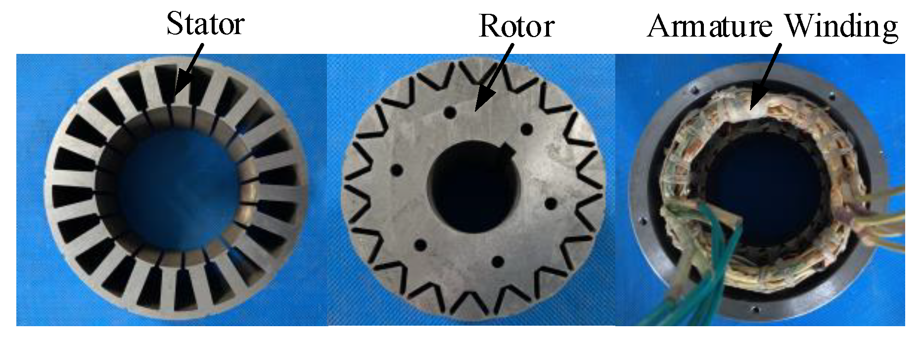
Figure 1 shows the prototype of the proposed 20/18-pole five-phase FTPMSM [21]. Owing to the single-layer concentrated winding and fault-tolerant tooth used in the stator to achieve phase isolation, a good fault-tolerant capacity can be achieved. Meanwhile, the adoption of single-layer concentrated windings will bring about MMF harmonics [22]. To overcome this problem, uneven air gap technology is adopted. The centers of the stator and rotor are not set the same. Then, by optimizing the eccentricity height of the rotor, the ideal sinusoidal back-EMF can be achieved. Additionally, the cogging torque can be reduced. Therefore, with the special design, this five-phase FTPMSM can possess high fault tolerance while ensuring good basic performance.
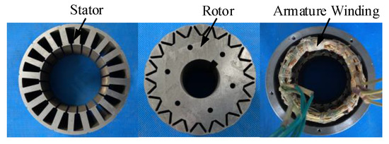
Figure 1.
Prototype of five-phase FTPMSM.
The ratio of mutual-inductance to self-inductance of this motor is only 0.22%, demonstrating the very small phase coupling and high fault tolerance. In addition, the total harmonic distortion (THD) of back-EMFs is only 1.7%, which demonstrates that the back-EMFs are quite sinusoidal. Furthermore, the relevant parameters of the five-phase FTPMSM are listed in Table 1.

Table 1.
Parameters of the FPFTPM motor.
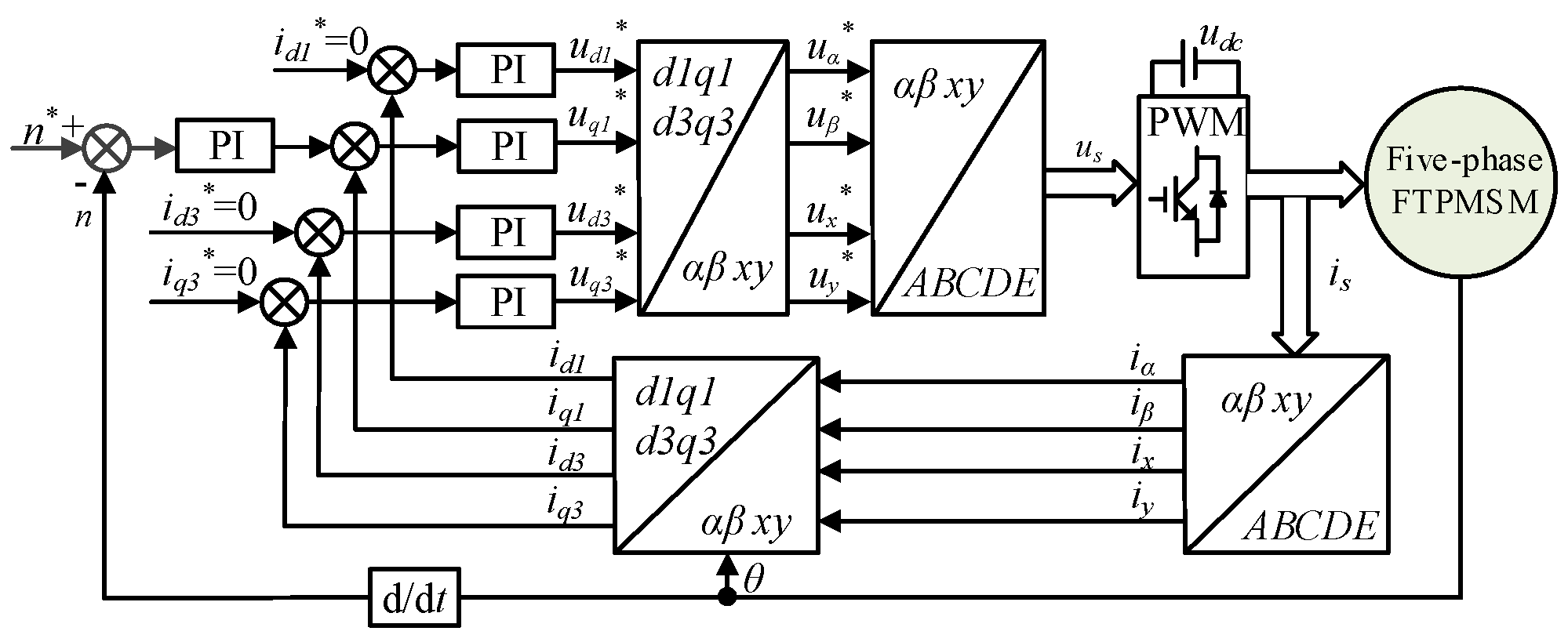
The FOC drive structure block diagram of the five-phase FTPMSM under the normal operation is shown in Figure 2. For a five-phase FTPMSM with a five-phase drive, the additional power loss is generated by the third harmonic component in the d3-q3 subspace. Thus, this component should be controlled to zero. To further suppress the third harmonic current, two closed-loop current controllers are added in the d3-q3 subspace. From Figure 2, it can be seen that based on the coordinate transformation matrices of the five-phase motor system, the FOC operation of the five-phase FTPMSM can be realized by adopting the corresponding PWM generation method.
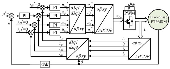
Figure 2.
Block diagram of the FOC drive system of the five-phase FTPMSM.
3. Conventional SMOTC Strategy Based on Reduced-Order Transformation Matrices
3.1. Principle Analysis Reduced-Order Transformation Matrices
The reduced-order decoupling transformation matrices are the key to achieving the fault-tolerant operation for the FOC drive system. The input phase currents of the five-phase FTPMSM under normal conditions are expressed as:
where γ = 72° and Im is the phase current amplitude.
Typically, to ensure the motor can continually operate under fault conditions, the equivalent torque-producing MMF is necessary to be provided. For example, when phase-A is open-circuited, the amplitude and phase angle of the remaining four-phase winding currents have to be changed to a certain degree. To maximize the fault-tolerant operation’s torque production, the equal amplitude control method of fault-tolerant currents [18] is adopted in this study. In addition, because the stator windings of the five-phase FTPMSM employ the star connection, the sum of the phase currents should be zero. Thus, adding this constraint, the target currents of the remaining four phases can be obtained as:
According to (2), the remaining four-phase currents can be distributed into the α-β subspace, the z subspace, and the zero-axis subspace. In this case, the first two columns of the inverse matrix of Clark transform can be expressed as:
Aiming to ensure that the electromechanical energy conversion only occurs on the α-β plane, the z subspace and the zero-axis subspace should be perpendicular to the α-β subspace. Thus, the vectors in the z subspace and the zero-axis subspace can be solved as:
Therefore, based on (3) and (4), the inverse Clark transformation can be obtained as:
Correspondingly, the reduced-order Clark transformation matrix can be obtained as:
Since the z subspace and the zero-axis subspace present null electromechanical energy conversion subspace, the corresponding Park transformation matrix is expressed as:
where θ is the rotor position. Additionally, the Park inverse transformation matrix is:
Therefore, by employing the reduced-order decoupling transformation matrices (5)~(8) under the open-circuit fault of phase A, the fault-tolerant operation of the FTPMSM FOC drive system can be obtained.
3.2. Problems Description
The above-mentioned FTC strategy based on the reduced-order decoupling transformation matrices is easy implementation, but the torque ripple and the dynamic response performance of the motor drive system under fault conditions are not considered, which will have a great influence on the dynamic and steady-state performance of the FTC system. The existing problems of the conventional FOC-based FTC drive system mainly include:
- (1)
- According to the traditional derivative calculation of the magnetic coenergy as regards the rotor position [23], and using (5)~(8) and the relationship between the back-EMFs and the flux linkages, the torque expression under the phase-A open-circuit fault condition can be obtained as:From (9), it can be noted that the torque ripples under the fault contain zero-sequence components, which is related to the zero-sequence current iz and rotor position θ. When an open-circuit fault occurs, to ensure a ripple-free torque operation, iz should be controlled to zero. Consequently, an additional control module is needed to be added, which is not conducive to the minimal reconfiguration of the drive system under fault-tolerant operation. In addition, the complexity of the algorithm is increased.
- (2)
- For the PM motors under fault conditions, the saturation effect and cross-coupling effect are more obvious. Therefore, with the influence of the fault, the amplitude of inductances and PM flux linkages may have some change and harmonics compared with that under normal conditions.To solve this issue, some research has been carried out. Robust design optimization can effectively improve the robustness of the variation of the amplitude of inductances and PM flux linkages [24], but this kind of scheme should be implemented in the motor design stage. In [13], the sliding mode control applied in the speed loop was proposed to suppress the torque ripple caused by the PM harmonic flux linkages. However, this scheme causes problems such as system oscillations and increased current harmonics. The online calculation and injection method of the third harmonic current were adopted after the fault [25], which could effectively restrain the torque ripple result from the third harmonic flux linkage of the rotor, but this control strategy needs multiple calculations of rotation transformation matrices to obtain the reference current values, which increases the complexity of the system implementation. Therefore, how to reduce or even eliminate the effect of changes in the amplitude of PM flux linkages on the operation performance of the system without increasing the complexity of the system remains to be overcome urgently.
- (3)
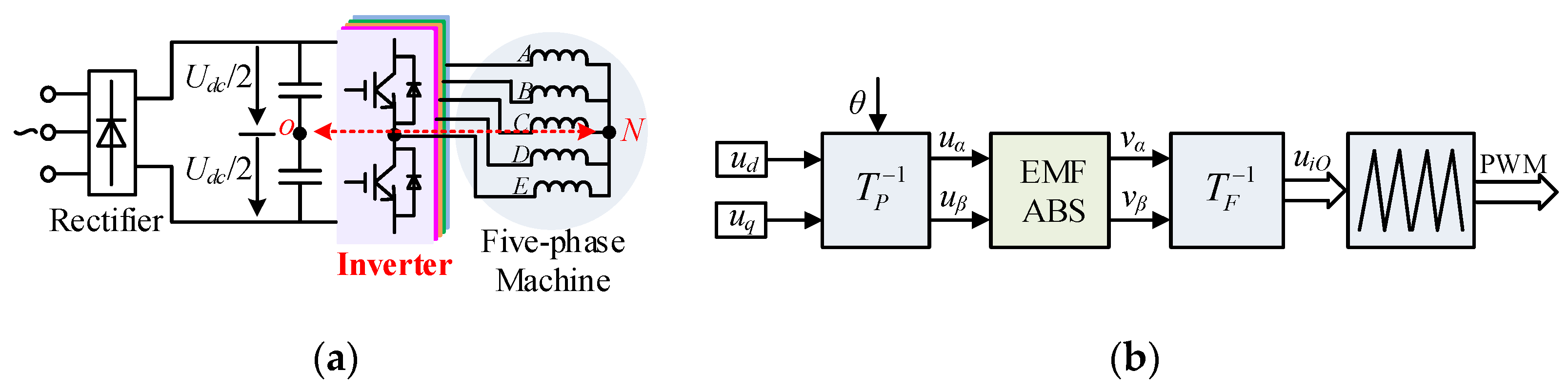
- A five-phase inverter is shown in Figure 3a, where N is the neutral point of the inverter, O is the midpoint of the capacitor, uiN (i = A,B,C,D,E) is the phase voltage, and uiO is the pole voltage. Usually, the inverter works by directly modulating the pole voltage. Nevertheless, in the case of an open-circuit fault, the phase voltage of the fault phase is modulated PWM thanks to the shift of the neutral point, which will affect the PWM modulation of the motor under the fault condition. In response to this problem, the existing literature generally adopts the back-EMFs compensation to weaken the influence of oscillating neutral, as shown in Figure 3b, but this scheme needs to add an additional back-EMFs compensation module, which is not beneficial to the minimal drive system reconfiguration under fault-tolerant operation.
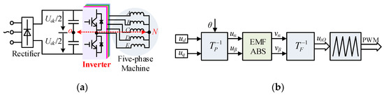 Figure 3. The fault-tolerant FOC system of five-phase motor. (a) Five-phase motor inverter drive system. (b) The way to weaken the influence of neutral point shift.
 - (4)
- The performance improvement under normal and fault-tolerant conditions is usually not considered at the same time. To achieve good fault-tolerant operating performance, the superior output performance of the motor drive system under normal operating conditions should be ensured. However, the vector control drive system based on the PI controller does not have good anti-interference performance against uncertain factors, such as load disturbance and motor parameter variation, which will have a great influence on the fault-tolerant operating performance.
4. FTC Strategy Based on Disturbance Adaption
To overcome the above-mentioned problems, with the design of a steady-healthy controller and the optimization of reduced-order coordinate transformation matrices, the FTC strategy based on disturbance adaptation is proposed in this paper.
4.1. Design of Current-Loop Steady-Healthy Controller
The fundamental idea of the FTC scheme is to ensure the output size of the electromagnetic torque and to restrain torque ripples at the fault state of the motor. According to [26], a steady-healthy controller of the speed loop was constructed based on the ripple component of the electromagnetic torque result from the fault. With the adoption of a speed-loop steady-healthy controller of the five-phase FTPMSM, its drive system can possess good robustness to various open-circuit faults. Furthermore, owing to the healthy-steady controller that is designed based on the system parameter variations and unknown load disturbance, the drive system presents good anti-load-disturbance capacity and resistance to parameter variations.
To further overcome the influence of the change of the PM flux linkage amplitude on the system’s performance at fault state, a current-loop steady-healthy controller is proposed in this paper.
The relationship between currents and voltages of a five-phase FTPMSM can be expressed as:
where Em = ωeψf, x = A,B,C,D,E, ix is the five-phase phase current, ux is the five-phase phase voltage, Rs is the stator resistance, Ls is the stator inductance, and θe is the rotor position electrical angle.
For the five-phase FTPMSM under fault conditions, considering the changed instantaneous PM flux, the back-EMF amplitude can be written as follows:
where Eb is the back-EMF amplitude under normal operation, and ΔEm is the deviation component of the back-EMF amplitude caused by faults. Therefore, in the following design process of the current-loop steady-healthy controller, Eb is designed to guarantee the system performance of the five-phase FTPMSM. Additionally, ΔEm is designed as the uncertain factor of the system.
For the deviation component of the back-EMF amplitude caused by faults, we assume that ΔEm = α1Eb, where α1 is unknown, but there is a limit that satisfies ǀα1ǀ ≤ α1m < 1 and α1m is the maximum value of α1. Subsequently, (10) can be rewritten as follows:
where α2 = 1 − (Lm/L), which meets the condition of 0 ≤ α2 < 1. In addition, Rm denotes the maximum of Rs, and Lm denotes the minimum of Ls. Both Rm and Lm are greater than zero, and they can be gained by the motor’s extreme operating condition.
Moreover, Let current error e take the form of e = I − i*, and i* is the current command. Therefore, (12) can also be rewritten as:
where θe is the rotor position with electric degree. According to the robustness control law [27], the steady-healthy control Eb of the current loop is expressed as follows:
where ε is a constant greater than zero, , and um is the boundary value of ui.
From the proposed current-loop steady-healthy controller in (14), it can be obtained that the motor parameter variation of the PM flux, inductance, and resistance caused by faults are comprehensively considered. Hence, the current-loop steady-healthy controller has better robustness to motor parameter variation caused by more obvious saturation effects and cross-coupling effects under fault conditions.
4.2. Design of the Enhanced Observer Analysis of The Stability
For the system (14), the steady-healthy controller (13) has uniform boundedness and uniformly final boundedness, which can be proved by the Lyapunov maximum-minimum approximation analysis method [28]. Define the Lyapunov function and derive it, then the following expression can be obtained as:
Taking (14) into (15), the following equation can be calculated as:
Hence, according to the standard argument in [28], the solution of the controlled system is uniformly ultimately bounded. Therefore, the stability of the controlled systems can be verified.
4.3. Modified Reduced-Order Coordinate Transformation Matrices
To overcome the effect of the neutral point shift under open-circuit fault and to meet the goal of the minimal system reconfiguration, the modified reduced-order coordinate transformation matrices are proposed in this paper.
From Figure 3, when the motor runs under normal conditions, the phase voltage is expressed as:
where udc indicates the dc line voltage, uiO = (A,B,C,D,E) indicates the voltage between the inverter output and the bus central point, uON indicates the voltage between the bus central point and the machine central point, and si is the switching function for the state of each bridge arm. si = 1 indicates that the upper switch is on, while si = 0 indicates that the lower switch is on.
Due to the star-connected type of the five-phase FTPMSM, the phase voltages meet as:
Substituting (17) into (18), uNO under different fault states can be obtained. When phase A open-circuit fault occurs, uNO is expressed as:
From (19), it can be known that the neutral potential under fault conditions oscillates when the motor is spinning. Although this effect can be effectively eliminated by using the back-EMF compensation, the added back-EMF compensation module is not good for minimizing the reconfiguration of the control drive system.
To overcome the problem caused by the traditional added back-EMF compensation module, the improved reduced-order inverse Clark transformation matrix under different faults is developed in this paper. Taking phase A open-circuit fault as an example, according to the decoupling model, the phase voltage is expressed as:
Substituting (17) and (19) into (20), the relationship between the αβ-axis phase voltage and the pole voltage under phase A open-circuit fault can be obtained as:
When phase A open-circuit fault occurs, iA = 0. Then, it can be obtained that uAN = eA. If a modified reduced-order inverse Clark transformation matrix can be designed by considering the back-EMF in (21), the effect of the neutral point shift will be suppressed.
The pole voltage can be obtained by the inverse Clark transformation matrix of the αβ-axis phase voltage. Then, the objective expression of the pole voltage is expressed as:
where TF*−1 is the modified Clark inverse transformation matrix, which is expressed as:
Substituting (22) and (23) into (21), the variable x in (23) can be solved that is x = 0.5 * 1.18 eA/uα.
Therefore, by utilizing the modified reduced-order transformation matrix in (23) to replace the traditional one in (5), the impact of oscillating neutral on the output performance of the drive system under open-circuit fault can be effectively suppressed.
Similarly, according to the above ideas and the reduced-order coordinate transformation matrices under the two-phase fault [29], the corresponding modified reduced-order coordinate transformation matrices can be obtained. For non-adjacent two-phase faults of phases B and E, the modified Clark inverse transformation matrix is expressed as:
where x1 = −1.3818 * 0.2981(eB + eE)/uα, y1 = 0.6909 * 0.2981 * (eB + eE)/uα and y2 = −2.1264 * 0.9176 (eB + eE)/uβ.
For adjacent two-phase faults of C and D, the modified Clark inverse transformation matrix is expressed as:
where x2 = 3.6178 * 0.2981(eC + eD)/uα, y3 = −1.8090 * 0.2981 * (eC + eD)/uα, and y4 = 1.3143 * 0.2166 (eC + eD)/uβ.
4.4. FTC Scheme
According to the fault-tolerant FOC strategy based on disturbance adaption, a five-phase FTPMSM drive control system is constructed, as shown in Figure 4. It can be known that in the proposed FTC strategy based on disturbance adaption, by designing the speed-loop and current-loop steady-healthy controllers, high-quality output torque under normal and fault operation conditions can be achieved; also, the good anti-interference performance of load disturbance, system parameter variation, and motor parament changes in fault state can be ensured. In addition, the modified reduced-order Clark inverse transformation matrix is designed to eliminate the influence of oscillating neutral on the output performance of the motor control drive system at open-circuit faults. Furthermore, the proposed open-circuit FTC scheme does not require additional torque ripples suppression and back-EMFs compensation, which is beneficial to minimizing the complexity of reconstructing the drive system under fault-tolerant operation and simplifying the control algorithm.
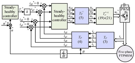
Figure 4.
Block diagram of the fault-tolerant FOC drive system for five-phase FTPMSM based on disturbance adaption.
5. Verification Results
Figure 5 shows the experimental platform of the proposed fault-tolerant FOC system for the five-phase FTPMSM. The proposed fault-tolerant FOC strategy is implemented on the controller of a dSPACE DS1007. The experimental platform also includes the FTPMSM motor prototype motor, the magnetic power brake, the torque sensor, the incremental encoder, the drive board, and the measure tools.
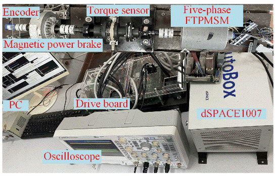
Figure 5.
Experimental platform.
To demonstrate the effectiveness of the proposed steady-healthy controller adopted by the proposed disturbance-adaption-based FTC system for the five-phase FTPMSM, Figure 6 and Figure 7 compare the experimental dynamic response waveforms achieved by the conventional PI controller and the steady-healthy controllers with the changed load at healthy operation, respectively. It can be clearly observed that for the traditional vector control system, the speed drops slightly under the condition of load increase, and the speed rises slightly under the condition of load decrease, although it can recover the commanded value quickly. By contrast, for the proposed control drive system based on steady-healthy controllers, the speed waveform is hardly affected by the load change, illustrating good robust ability to load disturbance. In addition, by comparing the steady-state operation of these two drive systems, it can be found that the torque ripple and sinusoidal current of the proposed drive system are comparable to those of the conventional control drive system with PI controller. Hence, it can be obtained that the steady-state operating performance of the motor drive system is be affected when the conventional PI controller is replaced by the steady-healthy controller.
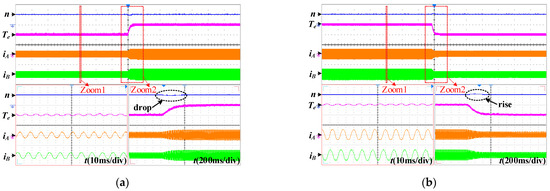
Figure 6.
Dynamic responses with the changed load in healthy operation for the conventional FOC (500 rpm/div, 2 Nm/div, 5 A/div). (a) Increased load. (b) Reduced load.
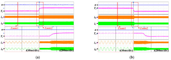
Figure 7.
Dynamic responses with the changed load in healthy operation for the proposed FOC (500 rpm/div, 2 Nm/div, 5 A/div). (a) Increased load. (b) Reduced load.
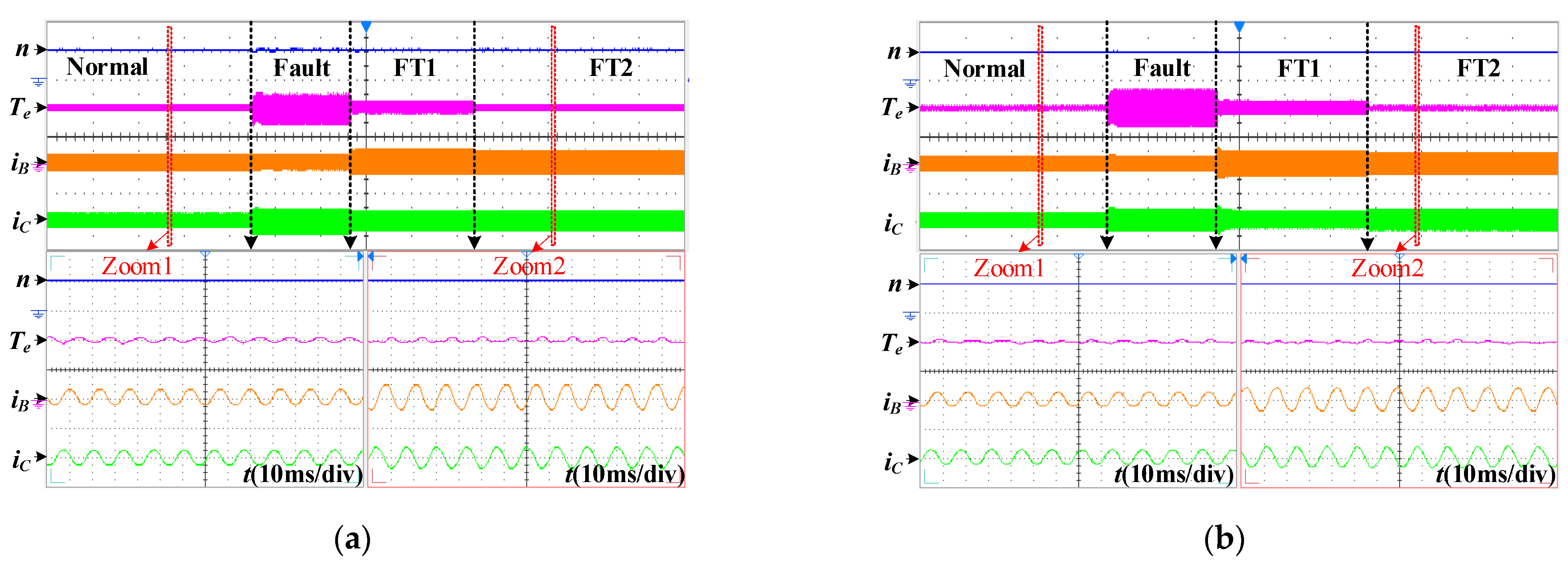
Figure 8 presents the conventional and proposed FTC drive systems in healthy, fault, and fault-tolerant operation at phase-A open-circuit fault state. In the experimental waveforms of traditional fault-tolerant vector control, the operation state of ‘FT1’ refers to the FTC strategy based on PI controllers that uses traditional reduced-order decoupling transformation matrices and does not adopt the back-EMFs compensation. The operation state of ‘FT2’ refers to the FTC strategy based on PI controllers that uses traditional reduced-order decoupling transformation matrices and the back-EMFs compensation. In the experimental waveforms of the proposed fault-tolerant vector control in this paper, the operation state of ‘FT1’ refers to the FTC strategy based on the steady-healthy controllers that adopts the traditional reduced-order decoupling transformation matrices and does not adopt the back-EMFs compensation method. The operation state of ‘FT2’ refers to the FTC strategy based on the steady-healthy controllers that adopts the modified reduced-order decoupling transformation matrices. From Figure 8a, it can be known that the torque ripple is restrained to some extent in the FT1-operated state compared with that at fault state. Additionally, the fault-tolerant currents are consistent with the theoretical derivation. By adopting the back-EMFs compensation method, the torque ripple can be further suppressed at the FT2-operated state, and the amplitude of fault-tolerant currents can be kept unchanged. Then, it demonstrates that the back-EMFs compensation can effectively weaken the impact of oscillating neutral. From Figure 8b, it can be observed that compared with FT1 operated state, the torque ripple in FT2 operated state is significantly reduced, which can be comparable to that under normal operation. Thus, the effectiveness of the modified reduced-order decoupling transformation matrices proposed in this paper can be verified.
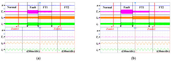
Figure 8.
Experimental waveforms under normal operation, fault operation, and phase-A open-circuit fault-tolerant operation. (500 rpm/div, 2 Nm/div, 5 A/div). (a) Traditional fault-tolerant FOC. (b) Proposed fault-tolerant FOC.
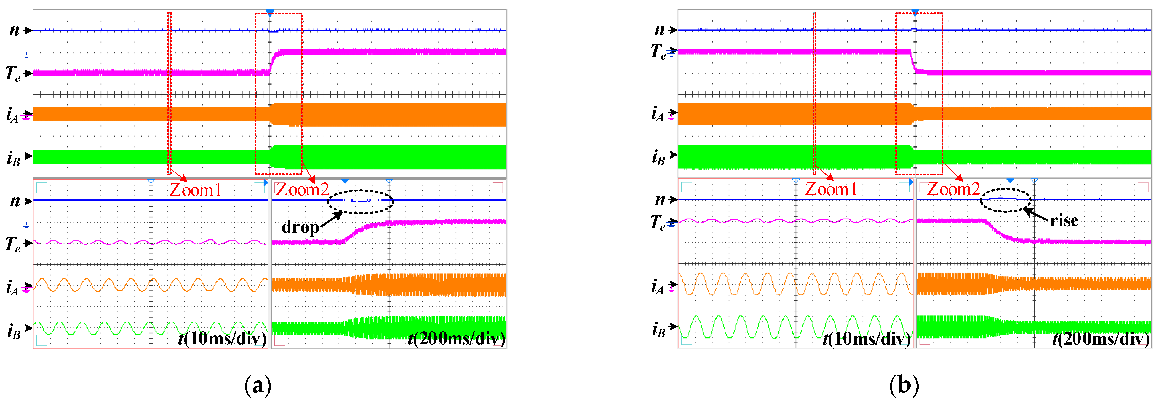
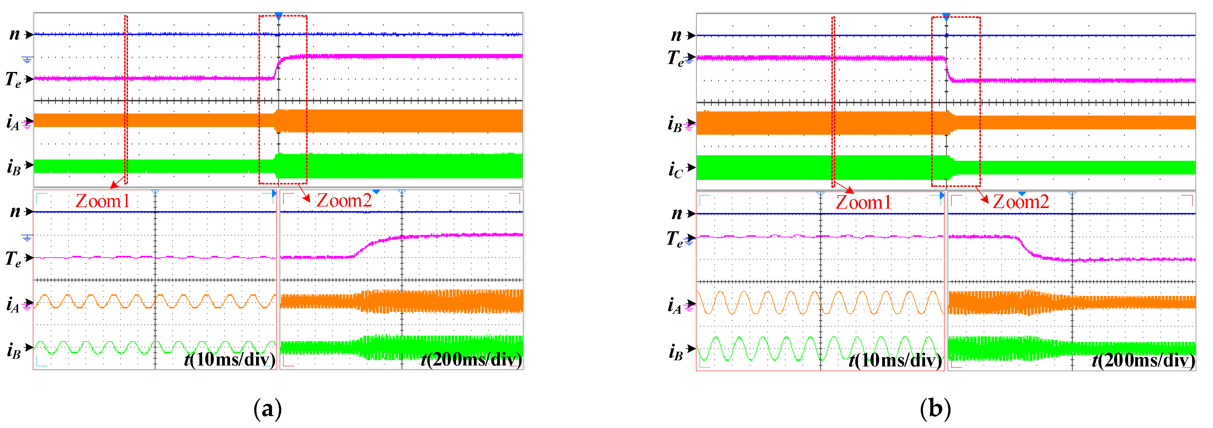
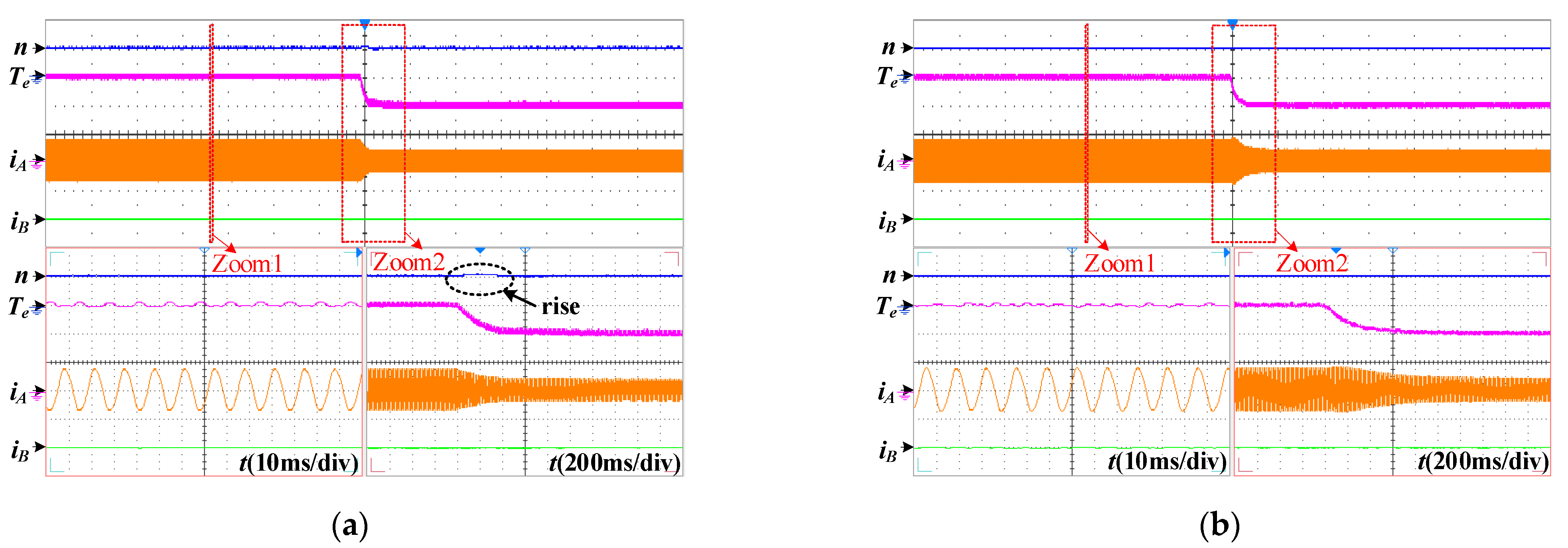
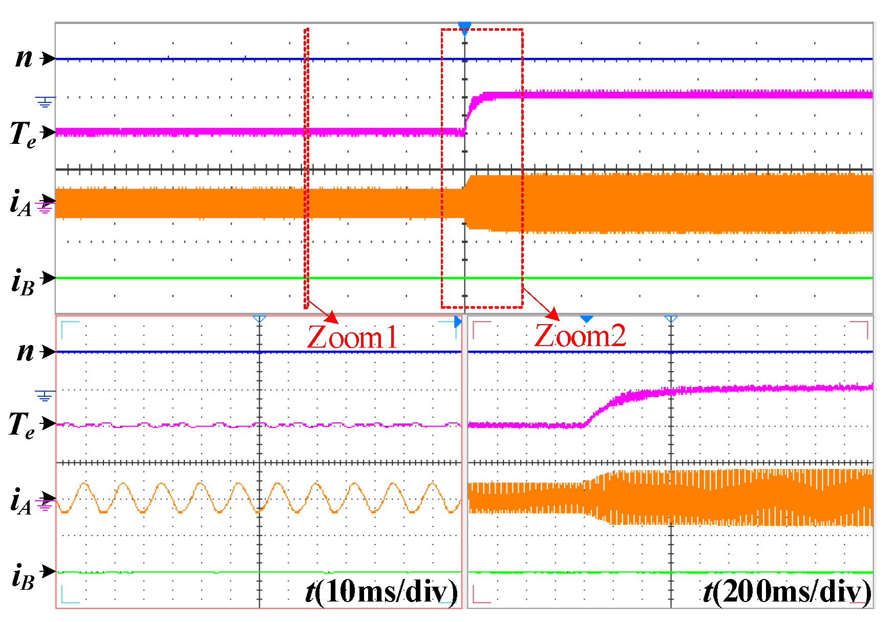
The dynamic waveforms of the conventional and proposed FTC scheme with a decreased load at phases A open-circuit fault-tolerant operation are shown in Figure 9. It can be found that both schemes can realize speed tracking under sudden load reduction, but the speed of the proposed fault-tolerant FOC system is hardly affected by load changes. Furthermore, the dynamic waveforms of the proposed FTC scheme with an increased load at phases A open-circuit fault-tolerant operation are shown in Figure 10. Comparing Figure 9b and Figure 10 under fault-tolerant operation with Figure 7 under normal operation, it can be summarized that for both at normal and fault-tolerant operation, the good disturbance rejection capacity and dynamic performance can be obtained under the proposed drive system.

Figure 9.
Dynamic responses with the reduced load at phase-A open-circuit fault-tolerant operation. (500 rpm/div, 2 Nm/div, 5 A/div). (a) Conventional fault-tolerant FOC. (b) Proposed fault-tolerant FOC.
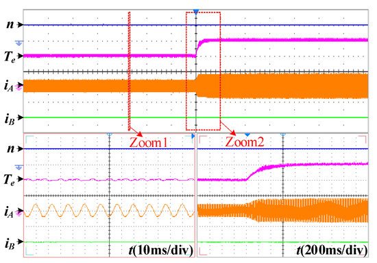
Figure 10.
Dynamic responses with the reduced load at phase-A open-circuit fault-tolerant operation. (500 rpm/div, 2 Nm/div, 5 A/div).
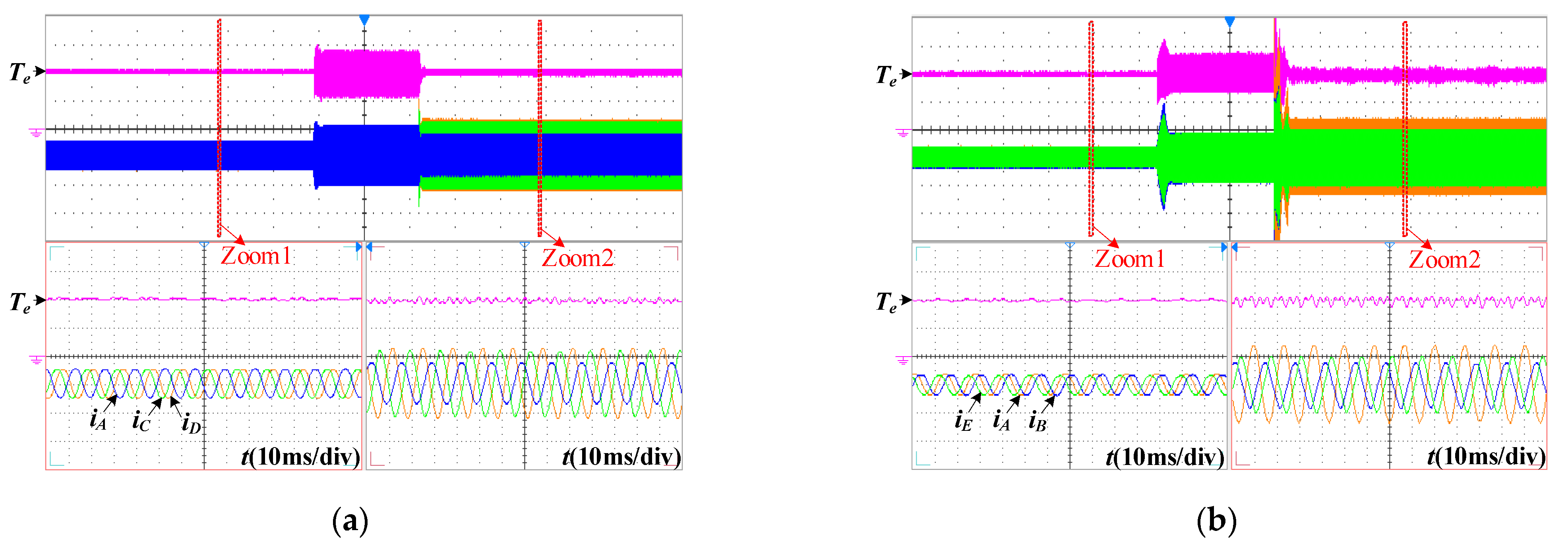
Furthermore, the waveforms of the proposed FTC drive system in healthy, fault, and fault-tolerant operation under non-adjacent and adjacent two-phase open-circuit faults are shown in Figure 11. It can be found that for the non-adjacent phase B and E open-circuit fault, the torque ripple under fault-tolerant conditions can be comparable to that under normal conditions. Additionally, for the adjacent phase C and D open-circuit fault, the torque ripple under the fault-tolerant condition can be better suppressed compared with the fault condition. Moreover, when non-adjacent two phases and adjacent two phases are open-circuit under fault-tolerant operation, the fault-tolerant currents under non-adjacent and adjacent two-phase open-circuit faults are consistent with the theoretical derivation.
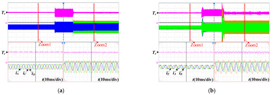
Figure 11.
Experimental results in normal operation, fault operation, and two-phase open-circuit fault-tolerant operation. (2 Nm/div, 5 A/div). (a) BE two-phase open-circuit fault. (b) CD two-phase open-circuit fault.
6. Conclusions
Based on the analysis of the problems existing in the conventional fault-tolerant vector control strategy, a fault-tolerant FOC strategy based on disturbance adaption was developed for the five-phase FTPMSM under an open-circuit fault circuit. The following advantages of the proposed fault-tolerant FOC strategy were obtained:
- (1)
- The speed-loop and current-loop steady-healthy controllers are constructed to provide good robust capacity to load disturbance, system parameter variation, and motor parameter variation under fault conditions. Apart from the high fault-tolerant capability, the proposed FTC provides favorable dynamic performances under fault conditions. Furthermore, because there is no need for the additional voltage compensation, the proposed FTC strategy is easily realized.
- (2)
- To eliminate the influence of oscillating neutral on the output performance at open-circuit fault, the modified reduced-order Clark inverse transformation matrix is designed by replacing the back-EMFs compensation in the traditional FTC algorithm. Hence, the minimal reconfiguration of the control drive system at fault-tolerant operation and the simple fault-tolerant algorithm can be achieved.
- (3)
- The proposed FTC strategy serves as a reference for the research that aims at the minimal drive system reconfiguration under faults and ensuring high-quality output torque both under normal and fault conditions.
Author Contributions
Conceptualization, L.Z.; methodology, C.D.; software, Y.W.; validation, L.Z., C.D., Y.W. and S.H.; formal analysis, C.D.; investigation, Y.W.; resources, L.Z.; data curation, S.H.; writing—original draft preparation, L.Z. and C.D.; writing—review and editing, Y.W. and S.H.; project administration, L.Z.; funding acquisition, L.Z. All authors have read and agreed to the published version of the manuscript.
Funding
This research was supported in part by the Natural Science Foundation of China under Grant 51907079, by the Natural Science Foundation of Jiangsu Province under Grant BK20190850, and by the China Postdoctoral Science Foundation under Grant 2019TQ0124, 2019M661748.
Institutional Review Board Statement
Not applicable.
Informed Consent Statement
Not applicable.
Data Availability Statement
Not applicable.
Conflicts of Interest
The authors declare no conflict of interest.
References
- Hang, J.; Wu, H.; Ding, S.; Huang, Y.; Hua, W. Cost Function-Based Open-Phase Fault Diagnosis for PMSM Drive System with Model Predictive Current Control. IEEE Trans. Power Electron. 2021, 36, 2574–2583. [Google Scholar] [CrossRef]
- Huang, W.; Hua, W.; Chen, F.; Zhu, J. Enhanced Model Predictive Torque Control of Fault-Tolerant Five-Phase Permanent Magnet Synchronous Motor with Harmonic Restraint and Voltage Preselection. IEEE Trans. Ind. Electron. 2020, 67, 6259–6269. [Google Scholar] [CrossRef]
- Wang, H.; Zhao, W.; Tang, H.; Tao, T.; Saeed, S. Improved Fault-Tolerant Model Predictive Torque Control of Five-Phase PMSM by Using Deadbeat Solution. IEEE Trans. Energy Convers. 2022, 37, 210–219. [Google Scholar] [CrossRef]
- Song, Z.; Zhou, F.; Yu, Y.; Zhang, R.; Hu, S. Open-Phase Fault-Tolerant Predictive Control Strategy for Open-End-Winding Permanent Magnet Synchronous Machines without Postfault Controller Reconfiguration. IEEE Trans. Ind. Electron. 2021, 68, 3770–3781. [Google Scholar] [CrossRef]
- Zhou, H.; Xu, J.; Chen, C.; Tian, X.; Liu, G. Disturbance-Observer-Based Direct Torque Control of Five-Phase Permanent Magnet Motor under Open-Circuit and Short-Circuit Faults. IEEE Trans. Ind. Electron. 2021, 68, 11907–11917. [Google Scholar] [CrossRef]
- Saeed, M.S.R.; Song, W.; Yu, B.; Wu, X. Low-Complexity Deadbeat Model Predictive Current Control with Duty Ratio for Five-Phase PMSM Drives. IEEE Trans. Power Electron. 2020, 35, 12085–12099. [Google Scholar] [CrossRef]
- Zhang, L.; Zhu, X.Y.; Cui, R.H.; Han, S. A Generalized Open-Circuit Fault-Tolerant Control Strategy for FOC and DTC of Five-Phase Fault-Tolerant Permanent-Magnet Motor. IEEE Trans. Ind. Electron. 2022, 69, 7825–7836. [Google Scholar] [CrossRef]
- Sen, B.; Wang, J. Stationary Frame Fault-Tolerant Current Control of Polyphase Permanent-Magnet Machines under Open-Circuit and Short-Circuit Faults. IEEE Trans. Power Electron. 2016, 31, 4684–4696. [Google Scholar]
- Chen, Q.; Gu, L.; Lin, Z.; Liu, G. Extension of Space-Vector-Signal-Injection-Based MTPA Control into SVPWM Fault-Tolerant Operation for Five-Phase IPMSM. IEEE Trans. Ind. Electron. 2020, 67, 7321–7333. [Google Scholar] [CrossRef]
- Xiong, C.; Guan, T.; Zhou, P.; Xu, H. A Fault-Tolerant FOC Strategy for Five-Phase SPMSM with Minimum Torque Ripples in the Full Torque Operation Range under Double-Phase Open-Circuit Fault. IEEE Trans. Ind. Electron. 2020, 67, 9059–9072. [Google Scholar] [CrossRef]
- Guzman, H.; Duran, M.J.; Barrero, F.; Zarri, L.; Bogado, B.; Prieto, I.G.; Arahal, M.R. Comparative Study of Predictive and Resonant Controllers in Fault-Tolerant Five-Phase Induction Motor Drives. IEEE Trans. Ind. Electron. 2016, 63, 606–617. [Google Scholar] [CrossRef]
- Zhou, H.; Zhao, W.; Liu, G.; Cheng, R.; Xie, Y. Remedial Field-Oriented Control of Five-Phase Fault-Tolerant Permanent-Magnet Motor by Using Reduced-Order Transformation Matrices. IEEE Trans. Ind. Electron. 2017, 64, 169–178. [Google Scholar] [CrossRef]
- Tian, B.; An, Q.; Duan, J.; Sun, D.; Sun, L.; Semenov, D. Decoupled Modeling and Nonlinear Speed Control for Five-Phase PM Motor under Single-Phase Open Fault. IEEE Trans. Power Electron. 2017, 32, 5473–5486. [Google Scholar] [CrossRef]
- Tian, B.; Mirzaeva, G.; An, Q.; Sun, L.; Semenov, D. Fault-Tolerant Control of a Five-Phase Permanent Magnet Synchronous Motor for Industry Applications. IEEE Trans. Ind. Appl. 2018, 54, 3943–3952. [Google Scholar] [CrossRef]
- Zhang, L.; Fan, Y.; Cui, R.H.; Lorenz, R.D.; Cheng, M. Fault-Tolerant Direct Torque Control of Fve-Phase FTFSCW-IPM Motor Based on Analogous Three-Phase SVPWM for Electric Vehicle Applications. IEEE Trans. Veh. Technol. 2018, 67, 910–919. [Google Scholar] [CrossRef]
- Tian, B.; Sun, L.; Molinas, M.; An, Q.T. Repetitive Control Based Phase Voltage Modulation Amendment for FOC-Based Five-Phase PMSMs under Single-Phase Open Fault. IEEE Trans. Ind. Electron. 2021, 68, 1949–1960. [Google Scholar] [CrossRef]
- Tian, B.; Molinas, M.; An, Q. PWM Investigation of a Field-Oriented Controlled Five-Phase PMSM under Two-Phase Open Faults. IEEE Trans. Energy Convers. 2021, 36, 580–593. [Google Scholar] [CrossRef]
- Parsa, L.; Toliyat, H.A. Fault-Tolerant Interior-Permanent-Magnet Machines for Hybrid Electric Vehicle Applications. IEEE Trans. Veh. Technol. 2007, 56, 1546–1552. [Google Scholar] [CrossRef]
- Barrero, F.; Bermudez, M.; Duran, M.J. Assessment of a Universal Reconfiguration-Less Control Approach in Open-Phase Fault Operation for Multiphase Drives. Energies 2019, 12, 4698. [Google Scholar] [CrossRef] [Green Version]
- González-Prieto, I.; Durán, M.J.; Bermúdez, M.; Barrero, F.; Martín, C. Assessment of Virtual-Voltage-Based Model Predictive Controllers in Six-Phase Drives under Open-Phase Faults. IEEE J. Emerg. Selec. Top. Power Electron. 2020, 8, 2634–2644. [Google Scholar] [CrossRef]
- Zhang, L.; Fan, Y.; Lorenz, R.D.; Nied, A.; Cheng, M. Design and Comparison of Three-Phase and Five-Phase FTFSCW-IPM Motor Open-End Winding Drive Systems for Electric Vehicles Applications. IEEE Trans. Veh. Technol. 2018, 67, 385–396. [Google Scholar] [CrossRef]
- Zhang, L.; Zhu, X.Y.; Gao, J.; Mao, Y. Design and Analysis of New Five-Phase Flux-Intensifying Fault-Tolerant Interi-Or-Permanent-Magnet Motor for Sensorless Operation. IEEE Trans. Ind. Electron. 2020, 67, 6055–6065. [Google Scholar] [CrossRef]
- Gaeta, A.; Scelba, G.; Consoli, A. Modeling and Control of Three-Phase PMSMs under Open-Phase Fault. IEEE Trans. Ind. Appl. 2013, 49, 74–83. [Google Scholar] [CrossRef]
- Tamás, O.; Anton, R.; Ants, K.; Pedro, A.; David, P.; Jan, K.; Pavel, K. Robust Design Optimization and Emerging Technologies for Electrical Machines: Challenges and Open Problems. Appl. Sci. 2020, 10, 6653. [Google Scholar]
- Liu, G.; Lin, Z.; Zhao, W.; Chen, Q.; Xu, G. Third Harmonic Current Injection in Fault-Tolerant Five-Phase Permanent-Magnet Motor Drive. IEEE Trans. Power Electron. 2018, 33, 6970–6979. [Google Scholar] [CrossRef]
- Zhang, L.; Zhu, X.Y.; Xu, L.; Zhang, C.; Fan, Y. Simplified Universal Fault-Tolerant Direct Torque Control of FPFTPM Motor with Steady-Healthy Design under Open-Circuit Fault. IEEE Trans. Ind. Electron. 2022, 69, 6688–6699. [Google Scholar] [CrossRef]
- Xu, J.; Du, Y.; Zhang, B.; Fang, H.; Guo, H.; Chen, Y.H. Sensorless Fault Tolerant Control with Phase Delay Compensation for Aerospace FTPMSM Drives with Phase Open-Circuit and Short-Circuit Faults. IEEE Trans. Ind. Electron. 2021, 68, 4576–4585. [Google Scholar] [CrossRef]
- Chen, Y.H. On the Deterministic Performance of Uncertain Dynamical Systems. Int. J. Control 1986, 43, 1557–1579. [Google Scholar] [CrossRef]
- Zhou, H.; Zhou, C.; Tao, W.; Wang, J.; Liu, G. Virtual-Stator-Flux-Based Direct Torque Control of Five-Phase Fault-Tolerant Permanent-Magnet Motor with Open-Circuit Fault. IEEE Trans. Power Electron. 2020, 35, 5007–5017. [Google Scholar] [CrossRef]


Publisher’s Note: MDPI stays neutral with regard to jurisdictional claims in published maps and institutional affiliations. |
© 2022 by the authors. Licensee MDPI, Basel, Switzerland. This article is an open access article distributed under the terms and conditions of the Creative Commons Attribution (CC BY) license (https://creativecommons.org/licenses/by/4.0/).