Article

A Novel Control Technique for Voltage Balancing in Bipolar DC Microgrids

1
CReSTIC, Reims University, 9 rue de Québec B.P 396, 10026 Troyes, France
2
CISIEV, Faculty of Sciences and Technology, Cadi Ayyad University, Marrakesh 40000, Morocco
3
FEMTO-ST Institute, University Bourgogne Franche-Comté, UTBM, CNRS, Rue Thierry Mieg, 90000 Belfort, France
*
Author to whom correspondence should be addressed.
Energies 2022, 15(9), 3368; https://doi.org/10.3390/en15093368
Submission received: 21 March 2022 / Revised: 26 April 2022 / Accepted: 28 April 2022 / Published: 5 May 2022

Abstract

:
The bipolar DC microgrid topology is characterized by three voltage levels and is able to transfer power more efficiently than a conventional DC microgrid. This paper proposes an advanced control strategy aiming to ensure the voltage balancing between the upper and lower terminals of a bipolar DC microgrid regardless of the distribution of loads. The proposed controller is based on the backstepping method, which is well known for its the robustness and the global asymptotic stability that can be guaranteed for the system. A particle swarm optimization algorithm has also been adopted for an optimal design of the proposed controller parameters. Simulation results in a Matlab/Simulink environment has been presented to verify the effectiveness and reliability of the proposed voltage-balancing controller.

1. Introduction

A microgrid has been defined according to CORDIS Europe as an advanced electric system formed of a series of electrical loads, power source elements (photovoltaic (PV) systems, fuel cells, wind turbines, etc.) and storage (batteries, flywheel, compressed air, etc.) connected to the local grid through a single point of connection The microgrid integrates management strategies controlling both the energy flow within the microgrid itself and the interchange of power with the supply grid [1]. One of the most important features of microgrids is that they are able to operate in two modes: the grid-connected mode and the islanded (off-grid) mode [2]. Microgrids can be built in rural and urban areas at multiple scales: low (such as a house/building with PV panels), medium (such as a factory) and large (such as a big university campus [3]).
Over the last two decades, significant progress has been made in DC/DC power converters, energy storage technologies (batteries, supercapacitor, etc.) and DC-based distributed energy resources (solar photovoltaics, fuel cell, etc.) [4]. In addition, an increasing number of DC-consuming devises such as LEDs, televisions, monitors and computers have been integrated into buildings. In addition, and new emerging technologies such as electric vehicles are DC [4]. Therefore, DC microgrids have become an attractive option and present a promising alternative to the AC counterpart. Various research studies have been focused on comparing the DC and AC microgrids [5,6,7]. It has been revealed that DC microgrids can transmit significantly more energy through distribution lines and require fewer power conversion stages, which decrease not only losses but also costs. DC microgrids present higher levels of power quality that are strongly intertwined with voltage stability. Moreover, DC microgrid control is simpler as there is no need for frequency synchronization and reactive power management. Despite the multiple merits of DC microgrids [8], appropriate control and safe design is always needed to avoid potential issues and maximize their benefits [4].
There are two wiring configurations of DC microgrids [9]: the unipolar (two-wire) and the bipolar (three-wire) configurations. This paper particularly addresses the bipolar configuration that generally offers two voltage levels: a positive to neutral or negative to neutral voltage (±350 V) and a positive to negative voltage (700 V), as shown in Figure 1. A voltage level of ±350 V has been considered in this paper since it is the most widely adopted level at the low- to medium-voltage bipolar DC power distribution network [10]. Among the key features of the bipolar configuration is that the loads can be connected at the appropriate voltage level due to the availability of two levels. Furthermore, the bipolar system may potentially continue supplying the loads under fault occurrence or loss of one pole. To summarize, the bipolar configuration has been proven to provide additional merits compared to conventional unipolar DC microgrids, including a high level of power transmission capability, reliability and efficiency [11]. Nevertheless, the bipolar DC microgrids still encounter some challenges that are not yet fully investigated [12].
First, the unequal load distribution across the positive and negative poles leads to voltage unbalance in the bipolar DC microgrid, which is undesirable owing to its impact on efficiency, power quality and stability [4]. To solve this problem, available literature has proposed the so-called voltage balancer that is a power electronic block commonly integrated with the grid-connected inverter, and it is able to equalize both poles’ voltages. In [10], the authors provide a comprehensive analysis of voltage balancers and introduces their different topologies. However, most studies have examined the voltage unbalance issue in a bipolar DC microgrid operating in grid-connected mode. Very little research has considered the islanded mode as well.
Otherwise, power electronic converters are fundamental elements in DC distribution. AC/DC and DC/DC converters are the two converter types commonly used in DC microgrids. To achieve a robust and efficient DC microgrid, an accurate design and control of the converters is required. Numerous studies have been conducted to improve the AC/DC converter’s structure [13,14,15] and enhance the system stability by proposing different linear [16] and nonlinear [17] control strategies. However, few studies on bipolar DC microgrids have focused on proposing improved design and developing advanced control techniques for DC/DC converters; the latter plays an equally essential role in DC microgrids as the AC/DC converters.
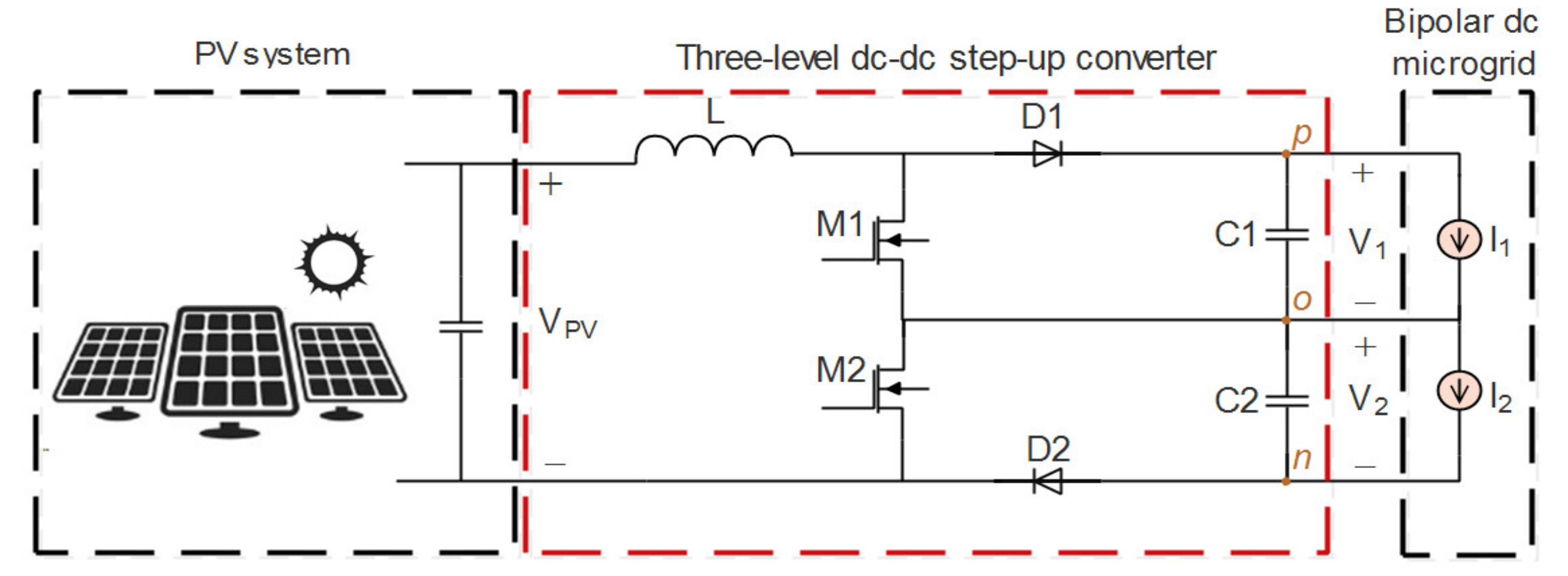
Due to the large accessibility and abundance, the PV solar plant is one of the most installed renewable power sources in DC microgrids. The PV system is connected to the bipolar DC bus through a DC/DC converter as depicted in Figure 1. This converter is the main interface that adapts the voltage level between the PV system and the DC bus. The majority of studies [18] on bipolar DC microgrids are generally confined to classical DC/DC converter topologies such as the conventional boost converter. Nevertheless, when the PV system is the principal power supply during islanded mode, the PV converter becomes the key element that must maintain the stability and reliability of the microgrid. Hence, more attentive design and control of the PV-connected DC/DC converter is needed.
The three-level boost converter topology shown in Figure 2 can be considered as a good candidate for the PV-connected DC/DC converter on the bipolar DC microgrids. This topology with two conversion stages can improve the system reliability. If an operational failure occurs in one stage or one DC bus, the converter continues working as a conventional topology. Additional merits of this suggested converter topology are the low switching losses, low voltage stress for semiconductor devices and reduced inductor current ripples [19].
This paper proposes a new robust voltage balance control based on a backstepping approach for a PV-connected DC/DC three-level boost converter on bipolar DC microgrids. The backstepping control method was chosen for its three significant superiorities compared to other control methods, namely the global asymptotic stability, the robustness and guaranteed transient performance.
The particle swarm optimization (PSO) algorithm is widely adopted as an optimized tuner due to its easy execution, quick convergence and its computational efficiency [20]. Therefore, a PSO technique has been used in this study to optimally predict the design parameters of the synthetized backstepping control law.
According to the above discussion, the contributions of this paper can be summarized as follows:
  • A novel voltage-balancing control based on a backstepping approach was proposed for a bipolar DC microgrid supplying unbalanced loads through a PV-fed three-level boost DC/DC converter. The proposed control technique enables reliable and accurate voltage balancing.
  • The PSO algorithm was used for an optimal estimation of the parameter’s values of the proposed backstepping-based controller.
  • The present work is supported by a theoretical study and validated through simulations under Matlab/Simulink.
The paper is structured as follows. The three-level DC/DC boost converter structure and operation are introduced in Section 2. The proposed voltage-balancing control is presented in detail in Section 3. In Section 4, simulation results verifying the working and performance of the developed controller are discussed. Finally, the conclusion is drawn in Section 5.

2. Three-Level DC/DC BoosT Converter

2.1. Topology Description

The three-level DC/DC boost converter (TLBC) topology shown in Figure 2 has three connection points (labeled p, o and n) enabling a three-terminal connection to the bipolar DC microgrid presented in Figure 1 (positive, neutral and negative, respectively). It consists of two power switches (MOSFETs) M1 and M2, diodes D1 and D2, an inductor L and two capacitors C1 and C2. Compared to other converters with the same function in the literature, this converter is more economical as it uses only two switches and one inductor. Among the main features of this topology are the low switching losses as one switch needs to handle only half the DC output voltage when it conducts, and the low inductor current ripple as the voltage across the inductor has three levels. Moreover, it is well known that the PV system maximum voltage rating can easily exceed the range that a single switching device can withstand. Therefore, the use of such multistage topology can be considered as a suitable solution of this issue.

2.2. Topology Operation

2.2.1. Symmetrical Operation

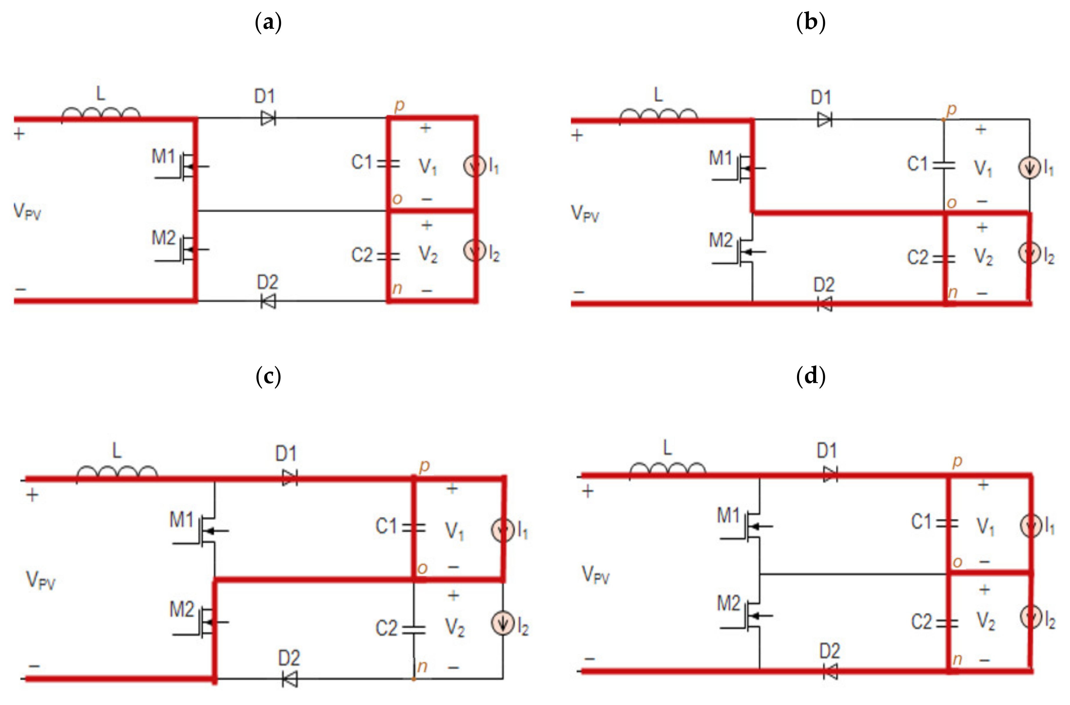
In the TLBC, the switches are driven by two PWMs with the same duty cycle ( d 1 = d 2 = d 0 , 1 ) and a phase difference of 180°. During symmetrical operation, capacitor voltages are considered equal V1 = V2. As can be seen in Figure 3, the converter operates in four principal states as follow:
State1 (Figure 3a): Both switches (M1 and M2) are ‘on’; the inductor is in charging mode. The capacitors C1 and C2 discharge their energy into the load.
State2 (Figure 3b): M1 is ‘on’ while M2 is ‘off’; the inductor can be in charging or discharging mode depending on the operating region. C2 is in the charging mode and C1 is discharging.
State3 (Figure 3c): When M2 is ‘on’ and M1 is ‘off’, the inductor can be in charging or discharging mode depending on the operating region. C1 is in charging mode and C2 is discharging.
State4 (Figure 3d): Both switches (M1 and M2) are ‘off’; the inductor is in discharging mode. The input source transmits energy to the output and satisfies the current demand via both capacitors.
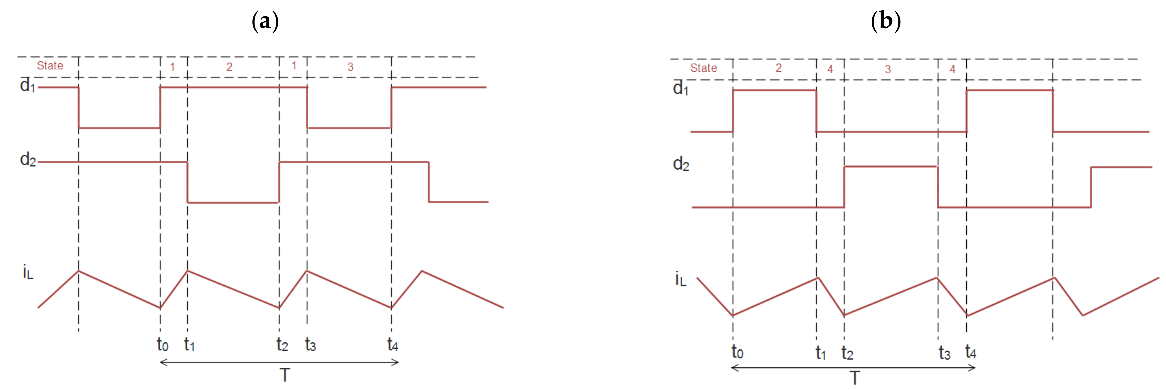
The TLBC operates in two regions depending on whether the input voltage (Vpv) is higher or lower than half of the output voltage (Vo = V1 + V2). Figure 4a shows the waveforms for the first region: “Vpv ≥ 1/2Vo” <=> “d ≤ 0.5” and Figure 4b for the second region: “Vi < 1/2Vo” <=> “d > 0.5”.
With symmetry, V1 and V2 are theoretically balanced as the inductor charges the capacitors alternatively.

2.2.2. Asymmetrical Operation

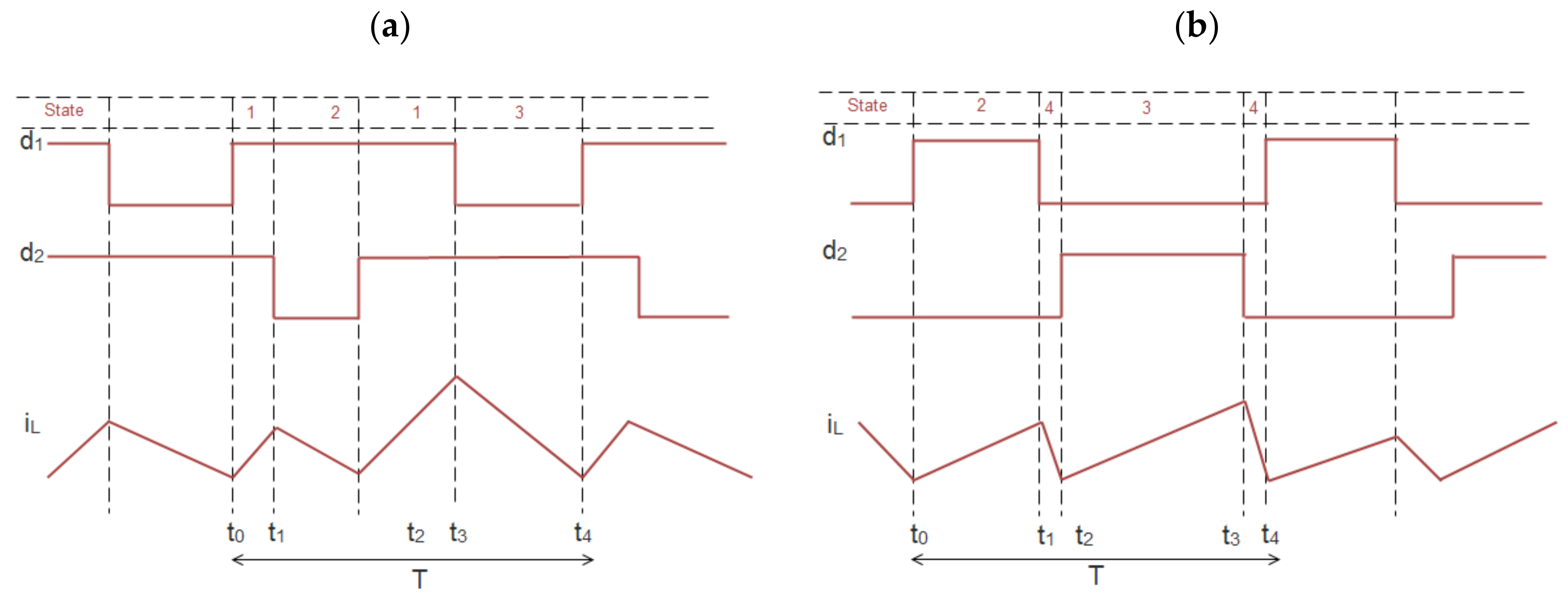
When the TLBC is used in the bipolar DC microgrid as presented in Figure 1, the loads on the upper and lower terminals (positive to neutral and negative to neutral) are generally not the same; hence, the load currents I1 and I2 will be unequal. These result in asymmetrical operation as depicted in Figure 5. In this case, one of the capacitor voltages go beyond the switch breakdown voltage, which may lead to switch damage. Therefore, the converter must be controlled to keep the voltages across C1 and C2 balanced whatever the nominal values of the connected loads.

2.3. Mathematical Modeling

Operating in continuous conduction mode CCM, the corresponding model of each state i 1 , 2 , 3 , 4 has the form
x ˙ t = A i x t + B i
where x = V 1 i L V 2 T is the state vector consists of voltages across capacitors and inductor current.
State1 i = 1
x ˙ t = A 1 x t + B 1 = I 1 C 1 V p v L I 2 C 2
State2 i = 2
x ˙ t = A 2 x t + B 2 = 0 0 0 0 0 1 L 0 1 C 2 0 x t + I 1 C 1 V p v L I 2 C 2
State3 i = 3
x ˙ t = A 3 x t + B 3 = 0 1 C 1 0 1 L 0 0 0 0 0 x t + I 1 C 1 V p v L I 2 C 2
State4 i = 4
x ˙ t = A 3 x t + B 3 = 0 1 C 1 0 1 L 0 1 L 0 1 C 2 0 x t + I 1 C 1 V p v L I 2 C 2
The final model of the converter is obtained by multiplexing all its four states as follows:
x ˙ = A 1 d ¯ 1 d ¯ 2 + A 2 d ¯ 1 d 2 + A 3 d 1 d ¯ 2 + A 4 d 1 d 2 x + B 1 d ¯ 1 d ¯ 2 + B 2 d ¯ 1 d 2 + B 3 d 1 d ¯ 2 + B 4 d 1 d 2
d1 and d2 are the duty cycles piloting M1 and M2, respectively; thus, they are control variables representing the two switches’ states.
After substitution and simplification, we obtain:
x ˙ = A d x + B = 0 1 d C 1 0 1 d L 0 1 d L 0 1 d C 2 0 x t + I 1 C 1 V p v L I 2 C 2
where d 1 = d 2 = d 0 , 1 .

3. Proposed Voltage Balance Control

As aforementioned, the voltage balancing is required for appropriate operation of the bipolar DC microgrid. Therefore, an efficient controller aiming to maintain the capacitor voltages V1 and V2 of the TLBC equal is developed in this section.

3.1. Design of the Proposed Backstepping-Based Controller

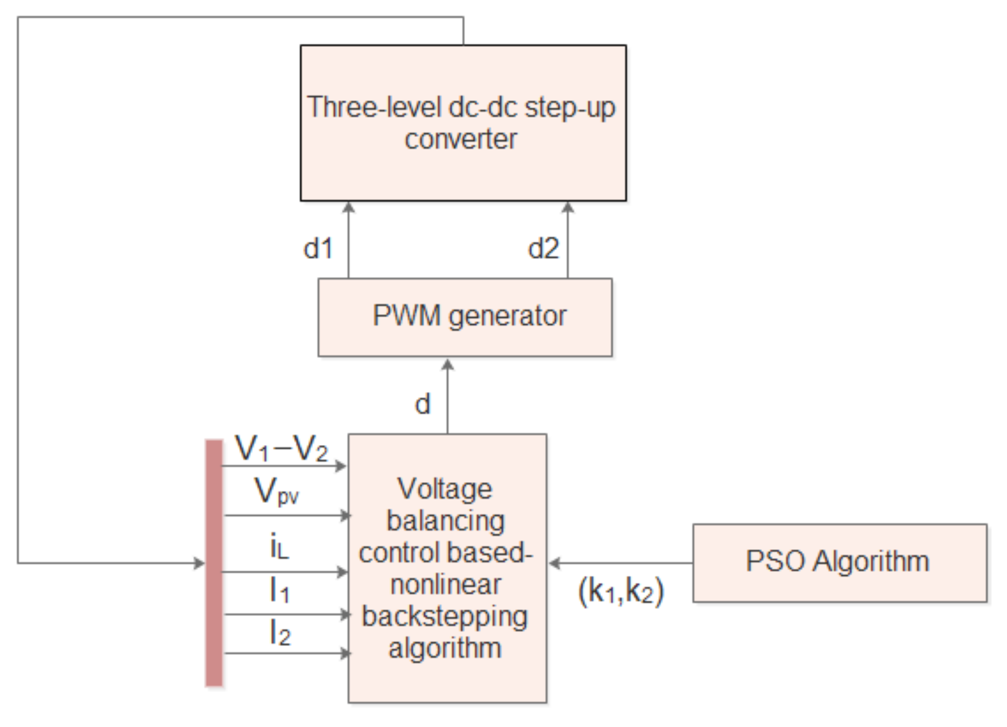
The structural view of the proposed controller is illustrated in Figure 6. It is based on a backstepping technique that has been proven very promising even for highly nonlinear systems. This technique ensures global stability and strong robustness against all parameter uncertainties [21]. The backstepping approach is a recursive strategy in which we can systematically design both feedback control laws and related Lyapunov functions.
According to the discussion about the operation and the mathematical modeling already given in Section 2, the obtained model of TLSC can be presented as below:
x ˙ 1 = ( 1 d ) x 2 C 1 I 1 C 1 x ˙ 2 = ( 1 d ) x 1 L ( 1 d ) x 3 L + V p v L x ˙ 3 = ( 1 d ) x 2 C 2 I 2 C 2
where x = V 1 i L V 2 T .
To simplify the backstepping controller design, Equation (8) is rearranged as follow:
Define the variables y 1 and y 2 as
y 1 = x 1 x 3 y 2 = x 2
Their derivatives are obtained as
y ˙ 1 = x ˙ 1 x ˙ 3 y ˙ 2 = x ˙ 2
From (8), we can form a new dynamic model as
y ˙ 1 = 1 d 1 C 1 1 C 2 y 2 I 1 C 1 + I 2 C 2 y ˙ 2 = 1 d L y 1 + V p v L
The procedure of designing the control law is described through the following steps:
Step1:
The errors are defined as
z 1 = y 1 z 2 = y 2 α 1
where α 1 is the stabilizing function.
The objective is to make z 1 0 . Consider a Lyapunov function V 1 = 1 2 z 1 2 . Its time derivative is V ˙ 1 = z 1 z ˙ 1 .
From (11) and (12)
z ˙ 1 = y ˙ 1 = 1 d 1 C 1 1 C 2 y 2 I 1 C 1 + I 2 C 2 = 1 d 1 C 1 1 C 2 ( z 2 + α 1 ) I 1 C 1 + I 2 C 2
Thus,
V ˙ 1 = z 1 1 d 1 C 1 1 C 2 z 2 + 1 d 1 C 1 1 C 2 α 1 I 1 C 1 + I 2 C 2
V ˙ 1 must be a negative definite to guarantee the global asymptotic stability. Therefore, z 1 z ˙ 1 0 is a condition that can be imposed by taking the stabilizing function as
α 1 = 1 1 d 1 C 1 1 C 2 k 1 z 1 I 1 C 1 + I 2 C 2 k 1 0
We obtain
V ˙ 1 = k 1 z 1 2 + 1 d 1 C 1 1 C 2 z 1 z 2
and
z ˙ 1 = k 1 z 1 + 1 d 1 C 1 1 C 2 z 2
Obviously, if z2 = 0, then V ˙ 1 = k 1 z 1 2 , and z1 is guaranteed to converge to zero asymptotically.
Step2:
We derive the error z2 as
z 2 = y 2 α 1 d d t z ˙ 2 = y ˙ 2 α ˙ 1
Based on (11), the time derivative of z2 is
z ˙ 2 = ( 1 d ) L y 1 + V p v L α ˙ 1
The time derivative of α 1 is obtained as
α ˙ 1 = 1 ( 1 d ) ( 1 C 1 1 C 2 ) ( k 1 z ˙ 1 I ˙ 2 C 2 + I ˙ 1 C 1 ) ) + d ˙ ( 1 C 1 1 C 2 ) ( 1 d ) 2 ( k 1 z 1 I 2 C 2 + I 1 C 1 )
The Lyapunov function is chosen as
V 2 = V 1 + 1 2 z 2 2
The time derivative of the Lyapunov function is expressed as
V ˙ 2 = V ˙ 1 + z 2 z ˙ 2
V ˙ 2 = k 1 z 1 2 + 1 d 1 C 1 1 C 2 z 1 z 2 + z 2 z ˙ 2 = k 1 z 1 2 + 1 d 1 C 1 1 C 2 z 1 z 2 + z 2 ( 1 d ) L z 1 + V p v L α ˙ 1 = k 1 z 1 2 + z 2 1 d 1 C 1 1 C 2 1 L z 1 + V p v L α ˙ 1
The derivative is negative definite by choosing
k 2 z 2 = 1 d 1 C 1 1 C 2 1 L z 1 + V p v L α ˙ 1
As a result, the Lyapunov function derivative satisfies
V ˙ 2 = k 1 z 1 2 k 2 z 2 2 0
where k 1 0 k 2 0 .
From (18) and (23), the time derivative of the error is expressed as
z ˙ 2 = k 2 z 2 1 d 1 C 1 1 C 2 z 1
Solving Equation (23) and using (19), the control law is synthetized as
( 1 d ) 2 1 C 1 1 C 2 1 L y 1 + k 1 + k 2 y 2 + V p v L + ( 1 d ) k 2 1 C 1 1 C 2 k 1 y 1 + I 2 C 2 I 1 C 1 + ( I ˙ 2 C 2 I ˙ 1 C 1 ) ( 1 C 1 1 C 2 ) + ( I 2 C 2 I 1 C 1 ) ( 1 C 1 1 C 2 ) d ( 1 d ) 2 1 C 1 1 C 2 1 L y 1 + d ˙ ( 1 C 1 1 C 2 ) k 1 y 1 + I 2 C 2 I 1 C 1 = 0

3.2. Parameters Selection of the Proposed Backstepping-Based Controller

For an optimal backstepping controller design, the unknown parameters k 1 and k 2 in the resulted control law shall be appropriately determined. The trial-and-error method is commonly used in solving a parameter estimation issue for most nonlinear controllers. However, such a method does not give the best setting of the parameters, and it is not a good solution especially when the complexity of the system increases. To deal with this issue, one of the different optimization algorithms presented in the literature, such as a genetic algorithm, particle swarm optimization, random search methods, ant colony optimization and shuffled frog leaping algorithm, can be employed. In this study, the particle swarm optimization (PSO) algorithm has been adopted.
The PSO is an evolutionary algorithm introduced by Elberhat and Kennedy in 1995 [22]. It is inspired from swarm behavior such as fish schooling and bird flocking. The PSO algorithm has been widely used for effectively solving optimization problems. It is characterized by its high quality, easy implementation and efficient computational performance [20].
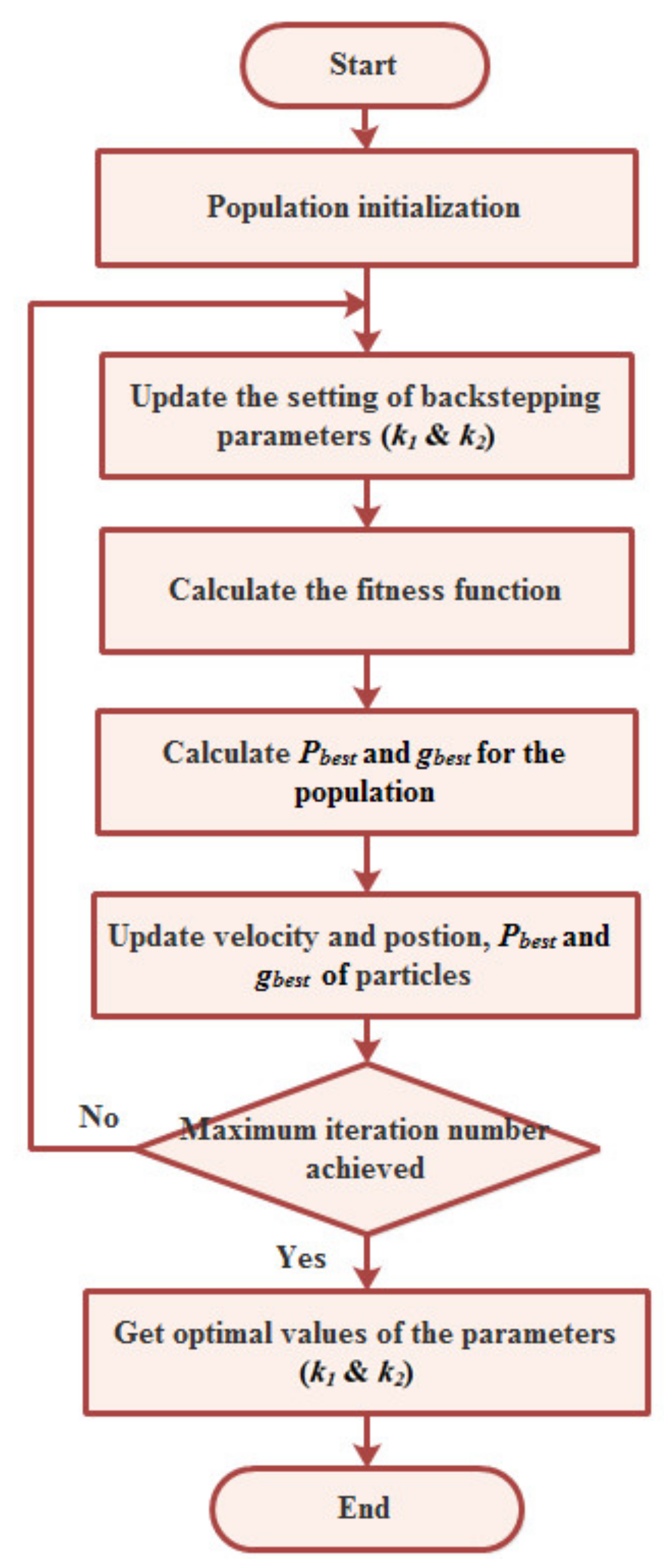
The PSO algorithm is first initialized with a population of random particles and then searches the best solution through continuous process updates. An arbitrary velocity is assigned to each particle for propagating in the search space toward the optimum. Each particle has a memory used to remember the best previous position reached by it, which is named the personal best position (Pbest). The particle with the best Pbest in the total swarm is called the global best particle (gbest). Consider swarm-enclosed n-particles moving in a d-dimensional search space; the ith particle of the population can be defined by the d-dimensional vector Xi = (xi1, xi2xid) and its velocity can be represented by another d-dimensional vector as Vi = (vi1, vi2vid). The following two equations (Equations (27) and (28)) are used to define the update of the particle’s position.
V i d k + 1 = w V i d k + c 1 r 1 x i d P b e s t t x i d k t + c 2 r 2 x i d g b e s t t x i d k t
x i d k + 1 t + 1 = x i d k t V i d k + 1 t + 1
where w is inertia weight, k is the number of iterations, c1 and c2 are called acceleration factors and r1 and r2 are random numbers uniformly distributed in the range [0, 1].
In this study, two parameters need to be optimally predicted: k 1 and k 2 . The position can be defined as:
e = V 1 V 2 2 . t r d t
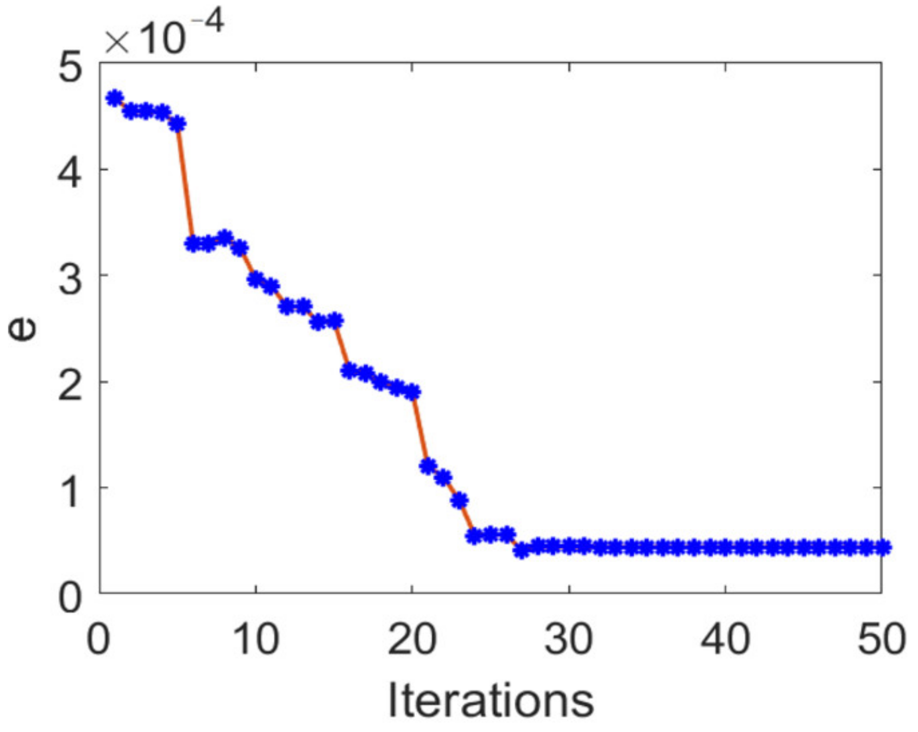
where tr is the time variable. The flowchart in Figure 7 illustrates the implementation of the PSO for parameters estimation of the proposed backstepping controller. The values assigned to the PSO algorithm parameters in this study are given in Table 1. The simulation is performed using Matlab/Simulink. More simulation details are provided in Table 2. For the PSO search processing in the simulation, after 50 times iterations, the convergence plot and the trend of the best global position is obtained as depicted in Figure 8. The best global position e decreases and gradually maintains its stability with the iterations number increasing. At the end of program, the obtained parameters values are k 1 = 1200 and k 2 = 154 .

4. Simulation Results

In this section, simulation results are provided to validate the proposed controller for voltage balancing of a bipolar DC microgrid. Simulations are executed using MATLABTM/Simulink. The parameters used in the simulation are listed in Table 2.
Two main scenarios verifying the performance of the designed voltage-balancing controller and highlighting its importance in solving the imbalance issue in the bipolar DC microgrid caused by the asymmetrical loading were examined.
Scenario1:
First, the studied system was simulated without and with the voltage-balancing controller. In this test, resistive loads with different values were connected to the TLSC output (upper (positive to neutral) and lower (negative to neutral) terminals of the bipolar DC bus) to yield the voltage imbalance. The resulting waveforms are plotted in Figure 9. Before using the voltage-balancing control, there was a mismatch of about 267 V between the capacitor voltages V1 and V2. Once the voltage-balancing control loop was applied at 0.3 s, V1 and V2 became equal, and the voltage balancing was immediately achieved. The proposed controller forced the difference between V1 and V2 to be zero.
Scenario2:
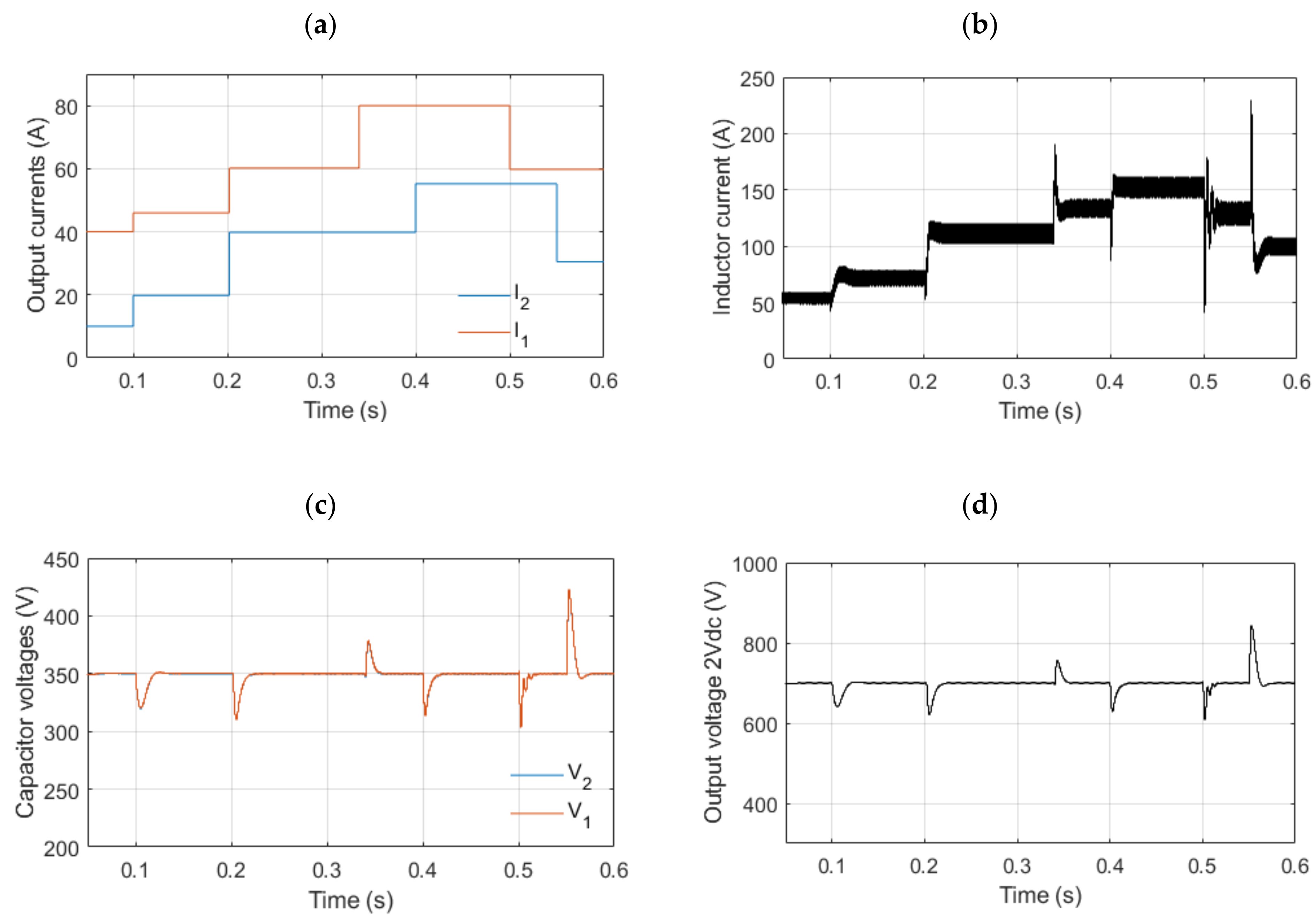
In this scenario, the robustness of the proposed voltage-balancing controller was tested under varying load currents I1 and I2 as shown in Figure 10a. The obtained waveforms of the inductor current (iL) and the voltages (V1, V2, 2Vdc) are depicted in Figure 10. As can be seen, the developed controller kept the voltages of both terminals (V1 and V2) equal (350 V) despite the different step changes of the load currents. Hence, the proposed voltage-balancing controller showed good performance in terms of reliability.

5. Conclusions

In this paper, an advanced voltage-balancing control has been developed for a bipolar DC microgrid supplying unbalanced loads through a PV-fed three-level boost DC/DC converter. This converter topology was chosen in this study due to its merits compared to the conventional boost converter commonly used in DC microgrids, including higher reliability and efficiency. Moreover, the proposed voltage-balancing control strategy is based on a nonlinear backstepping approach, which ensures the robustness and the global asymptotic stability of the system proven throughout Lyapunov stability criteria To enhance the dynamic performance of the proposed controller, PSO has been used for optimal estimation of its design parameters. The theoretical analysis was validated through simulations under Matlab/Simulink. The simulation results demonstrated the good performance of the proposed controller in terms of robustness and the settling time that is extremely small. Accordingly, the voltages of the upper (positive to neutral) and lower (negative to neutral) terminals of the bipolar DC microgrid are perfectly balanced, and the reliability of this system is improved. In future works, the proposed voltage-balancing control should be investigated experimentally.

Author Contributions

Conceptualization, H.D., I.S. and N.E.; Data curation, H.D., I.S. and N.E.; Formal analysis, H.D., I.S. and N.E.; Funding acquisition, H.D.; Investigation, H.D. and I.S.; Methodology, H.D. and I.S.; Project administration, I.S. and N.E.; Resources, N.E.; Software, H.D.; Supervision, I.S. and N.E.; Validation, H.D., I.S. and N.E.; Visualization, H.D.; Writing—original draft, H.D.; Writing—review & editing, I.S. and N.E. All authors have read and agreed to the published version of the manuscript.

Funding

This research was funded by the PHC Toubkal project (20/103-N°43692PB) and the APC was funded by Reims University.

Acknowledgments

This research work was financially supported by the PHC Toubkal project (20/103-N°43692PB).

Conflicts of Interest

The authors declare no conflict of interest.

Abbreviations

DCDirect Current
TLBCThree-level DC/DC Boost converter
PSOParticle swarm optimization
PWMPulse with modulation
CCMContinuous conduction mode

References

  1. CORDIS European Commission. Cordis.europa.eu. 2019. Available online: https://cordis.europa.eu/news/rcn/129412/en (accessed on 12 December 2021).
  2. Hirsch, A.; Parag, Y.; Guerrero, J. Microgrids: A review of technologies, key drivers, and outstanding issues. Renew. Sustain. Energy Rev. 2018, 90, 402–411. [Google Scholar] [CrossRef]
  3. Siemens. The Genius of Microgrids in Higher Education; Microgrid Knowledge Special Report; Siemens: Munich, Germany, 2020. [Google Scholar]
  4. Wang, R.; Feng, W.; Xue, H.; Gerber, D.; Li, Y.; Hao, B.; Wang, Y. Simulation and power quality analysis of a Loose-Coupled bipolar DC microgrid in an office building. Appl. Energy 2021, 303, 117606. [Google Scholar] [CrossRef]
  5. Justo, J.J.; Mwasilu, F.; Lee, J.; Jung, J.-W. AC-microgrids versus DC-microgrids with distributed energy resources: A review. Renew. Sustain. Energy Rev. 2013, 24, 387–405. [Google Scholar] [CrossRef]
  6. Ortiz, L.; González, J.W.; Gutierrez, L.B.; Llanes-Santiago, O. A review on control and fault-tolerant control systems of AC/DC microgrids. Heliyon 2020, 6, e04799. [Google Scholar] [CrossRef] [PubMed]
  7. Chen, D.; Xu, L. AC and DC Microgrid with Distributed Energy Resources. In Technologies and Applications for Smart Charging of Electric and Plug-In Hybrid Vehicles; Springer: Cham, Switzerland, 2016; pp. 39–64. [Google Scholar] [CrossRef]
  8. Magdefrau, D.; Taufik, T.; Poshtan, M.; Muscarella, M. Analysis and Review of DC Microgrid Implementations. In Proceedings of the 2016 International Seminar on Application for Technology of Information and Communication, Semarang, Indonesia, 5–6 August 2016. [Google Scholar]
  9. Dragičević, T.; Lu, X.; Vasquez, J.C.; Guerrero, J.M. DC microgrids—Part II: A review of power architectures, applications, and standardization issues. IEEE Trans. Power Electron. 2016, 31, 3528–3549. [Google Scholar] [CrossRef] [Green Version]
  10. Rodriguez-Diaz, E.; Chen, F.; Vasquez, J.C.; Guerrero, J.M.; Burgos, R.; Boroyevich, D. Voltage-level selection of future two-level lvdc distribution grids: A compromise between grid compatibiliy, safety, and efficiency. IEEE Electrif. Mag. 2016, 4, 20–28. [Google Scholar] [CrossRef] [Green Version]
  11. Wang, F.; Lei, Z.; Xu, X.; Shu, X. Topology deduction and analysis of voltage balancers for DC microgrid. IEEE J. Emerg. Sel. Top. Power Electron. 2017, 5, 672–680. [Google Scholar] [CrossRef]
  12. Chew, B.S.; Xu, Y.; Wu, Q. Voltage Balancing for Bipolar DC Distribution Grids: A Power Flow-based Binary Integer Mul-ti-Objective Optimization Approach. IEEE Trans. Power Syst. 2018, 34, 28–39. [Google Scholar] [CrossRef] [Green Version]
  13. Jadidi, S.; Badihi, H.; Zhang, Y. Passive Fault-Tolerant Model Predictive Control of AC/DC PWM Converter in a Hybrid Microgrid. IFAC-PapersOnLine 2020, 53, 12097–12102. [Google Scholar] [CrossRef]
  14. Tarasantisuk, C.; Chunkag, V.; Thounthong, P. Control of Parallel-connected AC to DC Converter with Droop Technique for DC Microgrid Application. Energy Procedia 2013, 34, 351–361. [Google Scholar] [CrossRef] [Green Version]
  15. Nassar, W.M.; Anaya-Lara, O.; Ahmed, K.H. A new adaptive instantaneous average current sharing technique for circulating current minimization among parallel converters in a LV DC-microgrid. Int. J. Electr. Power Energy Syst. 2022, 136, 107562. [Google Scholar] [CrossRef]
  16. Wu, B.; Gao, Z.; Zhou, X.; Ma, Y.; Wang, C. Research and Simulation of DC Microgrid Three-Phase AC-DC Converter Control Strategy Based on Double Loop. IEEE Access 2020, 8, 186448–186461. [Google Scholar] [CrossRef]
  17. Teodorescu, R.; Blaabjerg, F.; Liserre, M.; Loh, P.C. Proportional-resonant controllers and filters for grid-connected. IEE Proc.—Electr. Power Appl. 2006, 153, 750–762. [Google Scholar] [CrossRef] [Green Version]
  18. Kumar, J.; Agarwal, A.; Agarwal, V. A review on overall control of DC microgrids. J. Energy Storage 2019, 21, 113–138. [Google Scholar] [CrossRef]
  19. Chen, H.-C.; Liao, J.-Y. Design and Implementation of Sensorless Capacitor Voltage Balancing Control for Three-Level Boosting PFC. IEEE Trans. Power Electron. 2014, 29, 3808–3817. [Google Scholar] [CrossRef] [Green Version]
  20. Sahab, M.G.; Toropov, V.V.; Gandomi, A.H. 2—A Review on Traditional and Modern Structural Optimization: Problems and Techniques. In Metaheuristic Applications in Structures and Infrastructures; Newnes: Oxford, UK; Boston, MA, USA, 2013; pp. 25–47. [Google Scholar]
  21. Vaidyanathan, S.; Azar, A.T. Backstepping Control of Nonlinear Dynamical Systems; Advances in Nonlinear Dynamics and Chaos (ANDC); Elsevier Science: Amsterdam, The Netherlands, 2021; pp. 1–32. [Google Scholar] [CrossRef]
  22. Mullane, A.; Lightbody, G.; Yacamini, R. Adaptive control of variable speed wind turbines. Rev. Energ. Ren. Power Eng. 2001, 101–110. Available online: https://www.cder.dz/vlib/revue/nspeciauxpdf/upec_13.pdf (accessed on 12 December 2021).
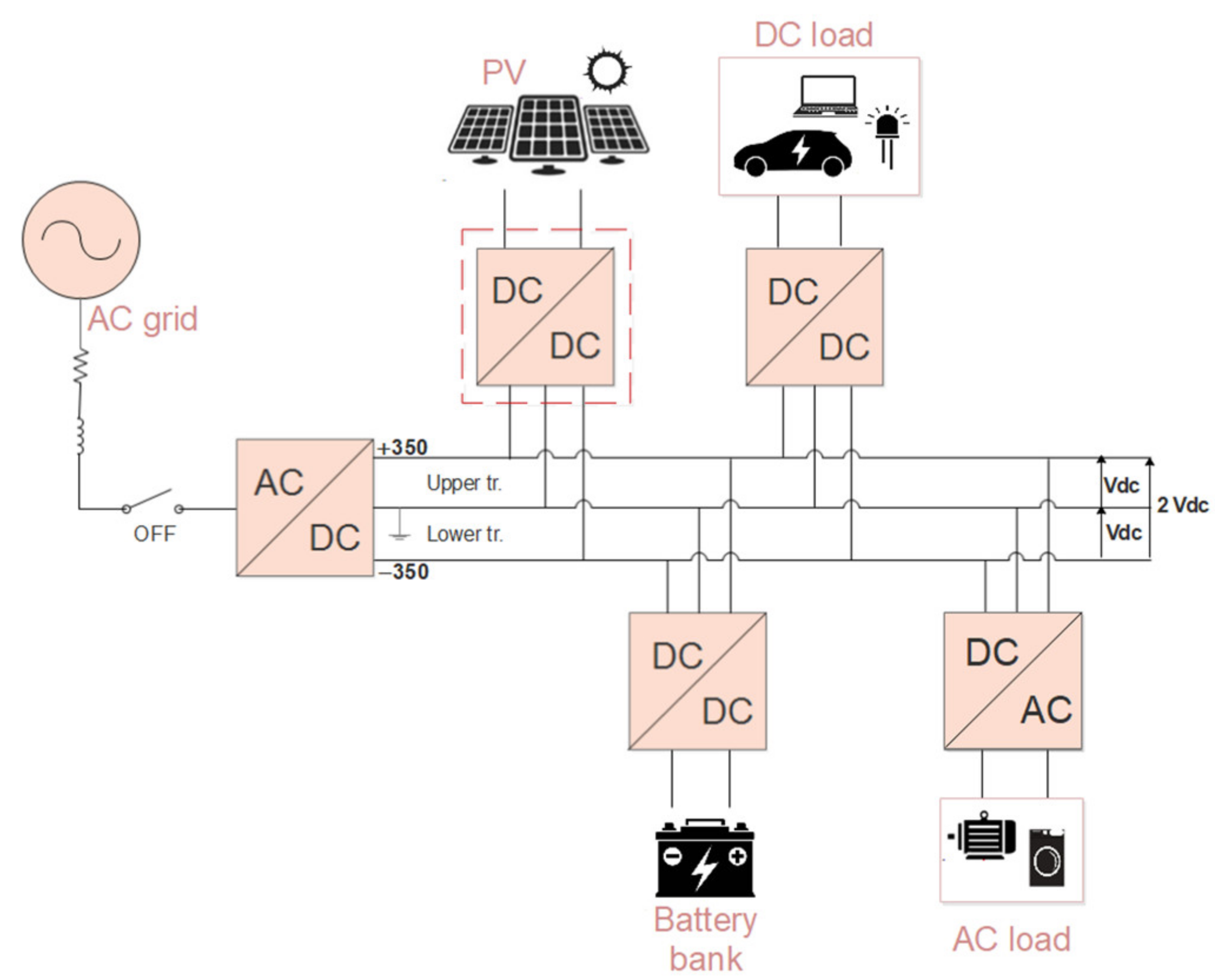
Figure 1. The bipolar DC microgrid architecture.
Energies 15 03368 g001
Figure 2. The PV-connected DC/DC three-level boost converter topology.
Energies 15 03368 g002
Figure 3. Possible states of the three-level DC/DC boost converter in CCM: (a) State1; (b) State2; (c) State3; and (d) State4.
Energies 15 03368 g003
Figure 4. Symmetrical operation of TLSC: (a) d > 0.5; and (b) d ≤ 0.5 (iL is the inductor current).
Energies 15 03368 g004
Figure 5. Asymmetrical operation of TLBC: (a) d > 0.5; and (b) d ≤ 0.5 (iL is the inductor current).
Energies 15 03368 g005
Figure 6. Scheme of the proposed voltage-balancing control.
Energies 15 03368 g006
Figure 7. The PSO algorithm for optimal estimation of the backstepping controller parameters.
Energies 15 03368 g007
Figure 8. Trend of the best global position.
Energies 15 03368 g008
Figure 9. Voltages of the upper and lower terminals before and after applying the voltage-balancing control loop.
Energies 15 03368 g009
Figure 10. The proposed voltage-balancing controller under varying loads current: (a) Output currents; (b) Inductor current; (c) Capacitor voltages; and (d) Output voltage.
Energies 15 03368 g010
Table 1. The parameters values of the PSO algorithm.
ParameterValue
Search space dimension d2
Maximum number of iterations kmax50
Number of particles n100
c10.8
c21.2
Inertia weight w0.8
Table 2. Simulation specifications.
PV array 100 kW (Sunpower SPR-305E-WHT-D)ParameterValue
No. of cells per module 96
Parallel strings66
Series connected modules per string5
Short circuit current Isc5.96 A
Open circuit voltage Voc64.2 V
Maximum power Pmpp305.2 W
Voltage at maximum power point Vmpp54.7 V
Current at maximum power point Impp5.58 A
Three-level boost converterParameterValue
Output DC voltage (2Vdc)2 × 350 V
Switching frequency30 kHz
Capacitors C1 & C21000 μF
Inductor L270 μH
Publisher’s Note: MDPI stays neutral with regard to jurisdictional claims in published maps and institutional affiliations.