1. Introduction
Typical ship propulsion systems contain many components and devices and are very complex. This is understandable, because in the general case, sea-going ships can certainly be considered as autonomous electric power units on which the crew works and functions. Sea-going ships become home to dozens, hundreds, and sometimes thousands of people, during long voyages. Aircraft carriers are a good example of travelling the seas and oceans for many months. In such cases, a reasonable question arises: how to ensure good dynamic characteristics of the ship’s movement and comfortable functioning of the entire system used by the crew.
Currently, marine propulsion systems are based on heat engines that operate on a diesel cycle. They have become one of the main options for this type of application. The main advantages of comparative diesel engines in contrast to other propulsion systems based on engines using a thermodynamic cycle are: low specific consumption of residual fuels and higher thermal efficiency. Modern merchant ships use marine propulsion systems equipped with ultra-long-stroke diesel engines that directly drive large, slow-running propellers [
1,
2,
3,
4]. Such systems use fewer cylinders and generate more power at lower shaft speeds, resulting in better propulsion performance as well as low repair and maintenance costs. However, it also causes higher torsional oscillations in long elements, which can lead to fatigue of the drive shafts [
5,
6,
7,
8,
9,
10,
11,
12]. Tests on various marine propulsion systems with five to seven cylinder engines have shown that engines with fewer cylinders have a correspondingly wider transverse barred speed range (BSR) and higher torsional stresses [
1].
Warships and cruise ships have higher demands on vibration and acoustic construction. Therefore, the study of vibration characteristics and the transmission mechanism is essential for damping vibrations and ensuring the safe operation of ships. The paper [
13] presents a model of suspended shafts formulated with the use of the analytical method. The shaft is simplified to a beam with a non-uniform cross section, while the bearings are considered as springs.
The reliability of propulsion shafting systems is a serious problem for ocean-going vessels because repairs in the middle of the ocean can be time consuming and spare parts must be available [
14,
15,
16,
17]. Analysis of this problem was carried out with the use of vibration modeling and experimental measurements on the propeller shaft system [
14]. The analysis was aimed at identifying the sources of failure of the flexible coupling connecting the diesel engine with the intermediate shaft. Torsional oscillations in the flexible coupling increased dramatically and then stopped abruptly. The modeling results showed that friction losses during power transmission through universal joints can act as a force inducing self-excited vibrations.
A simulation approach to mapping the ship’s movements on the wave, in interaction with the behavior of the propulsion system (diesel engine and propeller), was used in [
18]. The final goal was to develop a possibly complete simulator that would enable the main engine thermodynamics to be analyzed in various sea conditions, also in the unfavorable case of hull dynamic instability, and to properly manage other propulsion components. The latter aspect is of particular interest in some of the recent new power solutions for the decarbonization of ships, such as battery powered auxiliary electric motors to aid traditional diesel-mechanical propulsion (especially in difficult weather conditions). From this point of view, a proper analysis of the engine’s dynamic performance, which is influenced by individual sea states, is of fundamental importance for the intelligent management and control of shaft generators and auxiliary electric motors and batteries [
18].
Strong vibrations of the ship’s propeller shaft may evidently affect the dynamic response of the propulsion system and deteriorate the ship’s performance [
19,
20]. As vibrations form pairs that interact with each other, a better understanding of related vibrations is essential for dynamic prediction to improve the performance and reliability of a marine propulsion system. The paper [
19] proposes the study of coupled torsional-longitudinal vibrations of the shaft with the use of the solid method. The theoretical solution of coupled ordinary differential equations shows the accuracy of the proposed model.
Currently, much emphasis is placed on reducing energy consumption and harmful gas emissions from internal combustion engines [
21]. Current control technology allows the operating mode to be adapted to the currently required output parameters, while tuning of mechanical systems for torsional vibration is often ignored. Semi-active torsional vibration isolation systems are being developed using pneumatic flexible couplings with an angle of twist continuous adjustment [
21].
Calculations of non-smooth contact-based nonlinear autonomous systems susceptible to mono-instability have been proposed in [
22]. For the calculations, the method for determining periodic solutions of self-excited mechanical systems subjected to vibrations caused by friction was used.
The dynamics of the movement of a sea-going vessel depends on the dynamics of the propulsion system. Securing the operation of all ship subsystems and the comfortable functioning of the crew depend on the efficient supply of electricity to the ship’s subsystems. There are two important criteria to consider when solving this problem. The first criterion concerns the consideration of the maximum energy efficiency in the system. The second criterion is to maintain the maximum reliability of the entire system.
The mechanical energy is transferred from the engine to the ship propeller via a long drive shaft of various diameters, which is part of a complex motion transmission considered as a shafting system. Part of the mechanical energy is extracted from the ship’s motion transmission system to be converted into electrical energy. Shaft generators are used for this purpose. Generally, various types of generators are used as shaft generators: DC generators, asynchronous generators, synchronous generators and others. Each of the listed types of generators has advantages and disadvantages. Analyzing the properties of the generators [
3], it was decided that in the transmission systems of sea-going ships a synchronous generator, which ensures high quality of the generated electricity, should be used. Synchronous generators are characterized by an absolutely rigid static mechanical characteristic curve and provide the possibility of adjusting the reactive power in the electric power grid of a sea-going vessel depending on the value of the excitation current. Thanks to this property, the maximum voltage stabilization of the network of a sea-going vessel is achieved [
23,
24].
There are many schemes showing the mechanical energy take-up from the propulsion of a sea-going vessel [
15,
18,
23]. In this work, two general types of mechanical energy take-up from the propulsion system of a sea-going vessel have been distinguished. The first one consists of receiving the mechanical energy with the use of special reducers included in the motion transmission system (
Figure 1a). The second method of receiving mechanical energy consists of mounting the excitation winding of a synchronous generator directly on a long shaft connecting the drive engine with the ship propeller (
Figure 1b).
The following markings are used in
Figure 1: 1—drive engine, 2—ship propeller, 3—shaft generator, 4—reducer. Each of the types presented has advantages and disadvantages. The main advantage of connecting the shaft generator with the reducer results from the fact that the long shaft can rotate at a low rotational speed up to 100–300 rpm [
23]. The disadvantage of this solution is the need to use an additional reducer. This decreases the reliability of the motion transmission. When the shaft generator rotor is mounted directly on the transmission shaft, a large number of pole pairs of the synchronous generator is necessary at low shaft speeds. This solution significantly increases the size and weight of the synchronous generator. At higher shaft speeds, it is necessary to use a small diameter ship propeller with variable blade geometry. The choice of the motion transmission of the sea-going vessel propulsion system and its shaft generator is of course a complicated issue. During the selection process, several aspects should be considered: the economic aspect, operating costs, system reliability, quality of generated electricity, etc. It is not the purpose of this paper to perform a comparative analysis of the presented types of energy take-up from the propulsion system of a sea-going vessel. Transient processes in motion transmission with the mechanical energy take-up by the generator rotor, considered as an element of the propeller shaft of a sea-going vessel, were analyzed. The analyzed drive system is shown in
Figure 1b.
The aim of the work is to develop a mathematical model of the complex motion transmission of the propulsion system of a sea-going vessel as an electromechanical system with distributed mechanical parameters [
25,
26]. The analyzed motion transmission includes: the output shaft of the drive engine, flexible coupling, a long shaft containing elastic components and a ship propeller with variable blade geometry. In the electromechanical systems of ships, an important problem arises regarding the voltage stabilization of the autonomous network in terms of mechanical oscillation processes in the ship’s main propeller shaft. The influence of mechanical torsional oscillations in the shaft causes a significant deterioration of the quality of electricity, especially in the states of resonance and close to resonance. It leads to a decrease in the reliability of the entire object. Therefore, the mathematical model of the ship’s shaft generator prototype developed in this article, taking into account the susceptible transmission of motion with mechanical distributed parameters, makes it possible to analyze the problem mentioned above. The proposed model enables the analysis of both the theory of the mechanical field and the theory of electromagnetic circuits of a synchronous generator at a high level. On the basis of the developed model, modeling of electromechanical transient processes in the components of the motion transmission of a sea-going vessel was performed. The methods that will allow easy detection of early damage in ship propulsion systems are searched for. The presented method is an alternative method based on the use of the Hamilton-Ostrogradsky principle, which is an innovative approach describing the problem at the level of electromechanical energy conversion.
2. Mathematical Model of the Object
The mathematical model of motion transmission is formulated on the basis of the general theory of the mechanical field, which is based on the principles of the analytical mechanics of continual systems. On the basis of the ship shaft generator model developed in the article, at the level of systems with distributed parameters, complex dynamic processes in the shafting system of ship motion transmission were modeled and analyzed, as well as the influence of the latter on the qualitative and quantitative characteristics of the electricity power system of the facility. The developed model of the shaft generator is based on the modified Hamilton-Ostrogradsky principle, developed in our previous works [
5,
6,
23,
27]. This approach gives the simulation processes carried out at work on the energy level an original character on the energy level. Therefore, the general equation of rotational motion of a long shaft is used, which is presented on the basis of interdisciplinary variation approaches in the works [
5,
6,
9,
27,
28,
29,
30,
31]. At the ends of each elastic element of the shafting system, the first (Dirichlet), second (Neuman) and third (Poincaré) boundary conditions are added to the shaft equations, based on the famous d’Alembert’s principle [
23,
32].
Figure 2 shows a kinematic diagram of motion transmission in the ship’s propulsion (see
Figure 1b).
The following symbols are used in
Figure 2:
MT is torque of the drive engine including gearing,
MN is load torque of the propulsion,
mE is distributed electromagnetic torque of the shaft generator,
JT is moment of inertia of the drive engine including gearing,
JN is moment of inertia of the working mechanism (ship propeller),
L1, …,
L4 are lengths of respective elements of the shaft,
c1,2 is stiffness coefficient of the flexible coupling,
ν1,2 is dissipation factor of the flexible coupling,
x is spatial coordinate.
The general equation of motion of the rotating system, taking into account long elastic elements, can be presented in the form [
23,
33]:
where
j is number of long elastic elements in the shafting system,
φ(
x,
t) is function of the angle of the shaft rotation,
ρ is mass density of the shaft elements,
JP is polar moment of area of the shafts,
G is shear modulus,
ξ is internal dissipation coefficient,
t is time.
We write boundary conditions for Equation (1) on the basis of d’Alembert’s principle [
23]:
The system of Equations (1)–(7) creates a mixed (boundary) task. Equation (1) describes the physical processes in the shafting system (see
Figure 2). Expressions (2)–(7) describe the boundary conditions for Equation (1).
An important problem in the implementation of the mixed task is the method of integrating the system of Equations (1)–(7). Therefore, the method of discretization of spatial coordinates using the method of straight lines [
23] is used as follows:
where
i is the number of the derivative discretization point and Δ
x is the discretization step.
In order to improve the visualization of the discretization process,
Figure 3 shows a computational diagram of the ship motion transmission prototype.
Figure 3 shows
n = 90 discretization nodes. Virtual nodes of discretization of spatial derivatives are marked with asterisks [
7,
23]. The virtual node numbers in the lower part of
Figure 3 are shown in parentheses. Some real node numbers are shown at the top of
Figure 3 as numbers without parentheses.
Using the system of Equations (1)–(7) and dependency (8), taking into account
Figure 3, the system of discretized ordinary differential equations was determined. These equations describe the mathematical model of motion transmission occurring in the shafting system:
where
where
mi—internal friction moment of individual sections of the shaft (
Figure 2) where
i ∈ {1,2,3,4}. As the shaft generator is located on
Section 3 of the shaft, it was assumed for the remaining sections of the shaft (
Section 1,
Section 2 and
Section 4) that the internal friction moments were equal to 0.
where
ωk is angular velocity of discrete nodes of the mechanical system for
n =
k;
φk is angle of rotation of discrete nodes for
n =
k.
Analyzing Equation (16), it can be noticed that to solve the system of Equations (1)–(7), an unknown function, which describes the electromagnetic torque of the shaft generator, should be calculated. Therefore, a mathematical model of a salient-pole synchronous generator in phase coordinates [
34], which is loaded with resistive-inductive loads (simplified ship network model), was developed. In this case, for each stator phase winding, the phase resistance was connected in series with the load resistance, and the phase leakage inductance was connected with the load inductance.
Based on Kirchhoff’s voltage law and the Faraday principle of electromagnetic induction, for a conventional synchronous generator with a three-phase stator winding and an excitation winding and two damping windings in the rotor, we write the equations for the stator (armature) and rotor circuits [
23]:
where
Ψ is vector of total flux linkages,
u is vector of phase voltages,
i is vector of phase currents,
r is resistance matrix, subscript
S applies to the stator winding and
R applies to the rotor winding.
The elements of vectors and matrices in Equation (19) are as follows:
where
D refers to the damping winding along the direct coordinate,
Q refers to the damping winding along the quadrature coordinate,
f refers to the excitation winding along the direct coordinate,
rH is the load resistance.
The stator phase windings are star-connected. Therefore, on the basis of Kirchhoff’s current law, it can be written:
Equation (22) is analyzed as an equation of scleronomic constraints. This makes it possible to eliminate the C-phase winding equation.
According to the definition, we write the expression for calculation of the full flux linkages of the shaft generator:
where
LΣ is matrix of stator winding leakage inductances increased by inductances occurring in the ship network load,
LσR is matrix of rotor winding leakage inductance,
B is topological matrix,
ψ is vector of main flux linkages.
The elements of vectors and matrix in Equation (23) are as follows:
Using the Park transform, we write the equations of scleronomic constraints between the flux linkages of the stator and rotor of the generator:
where
Π is Park matrix and γ is average angle of rotation of the shaft generator rotor. The superscript
Π indicates the transformed Park coordinate system.
The average angle of rotation of the shaft generator rotor (see
Figure 3) is determined from the following dependency:
The vector of rotor flux linkages is determined according to the definition [
23] and Equations (23) and (26):
where
Lm is matrix of generator magnetization inductances and
im is vector of generator magnetizing currents, taking into account the armature reaction,
The vector of flux linkages of the generator is calculated from the dependency (29):
Taking into account the generator magnetization curve:
the matrix
M is simplified as follows:
Based on the dependencies (23) and (32), the expressions defining the currents in the shaft generator windings are obtained:
where in
On this basis, a system of differential equations of electromagnetic transient processes in a shaft generator can be derived:
The electromagnetic torque
MEM of the generator is determined according to the equation [
23]:
Finally, the distributed torque
mE of the shaft generator is determined by the relationship:
The following system of ordinary differential equations is subject to common integration: (9)–(11), (14), (15), (18), (38), (39) with the following dependencies: (12), (13), (16), (17), (20)–(22), (24), (25), (27), (28), (30)–(36), (40), (41).
3. Computer Simulation Results
For the modeling of electromechanical transient processes in the long propeller shaft of the ship, the prototype of the second type of motion transmission (see
Figure 1b) was used, the kinematic diagram of which is shown in
Figure 2.
The motion transmission was started by a drive engine (steam or gas turbine, internal combustion engine, etc.) through epicyclic gearing. The experiments were performed as follows. The propulsion was started by applying two moments at the ends of the motion transmission system. The angular speed of the drive engine was approximated by the exponential function of time: ω1 = 316(1 − exp(−0.05t2.3))/p0, where p0 is number of pole pairs of the shaft generator. At the same time, the shaft generator was disconnected from the ship’s network. During the start, the voltage of the excitation winding was reduced to 70% of the rated voltage. The generator was started from idle. Once the rotor neared the synchronous speed, the generator was connected to the ship’s power grid. The resistive-inductive load as well as the excitation voltage were increased to the rated values. Then, the symmetrical three-phase short-circuit condition of the machine armature windings was analyzed. In a real system, the power-system automation would disconnect the generator from the grid and from the excitation voltage source. During modeling, the short circuit was deliberately extended to 7 s.
The results of the computer simulation of the ship’s motion transmission system are presented in the form of graphs, which are the subject of the analysis. The non-stationary dependencies of both mechanical and electrical functions, which describe one electromechanical system, are presented. One system of differential equations was integrated by the 4th order explicit Runge-Kutta method.
The parameters of the system shown in
Figure 2 are as follows.
Motion transmission parameters: lengths of shafting elements are L1 = 1.65 m, L2 = 4.20 m, L3 = 1.65 m, L4 = 1.65 m, diameters of shafting elements are D1 = 0.65 m, D2 = 0.30 m, D3 = 0.75 m, D4 = 0.30 m, N = 90, JT = 2000 N·m2, JN = 3000 N·m2, G = 8.1·1010 N·m2, ξ = 3000 N·m2·s, c1,2 = 200,000 N·m, ν1,2 = 2000 N·m·s.
Shaft generator parameters are UN = 6 kV, UfN = 42 V, PN = 630 kW, ω0 = 314 s−1, rS = 5.4 Ω, rf = 0.252 Ω, rD = 5.42 Ω, rQ = 5.42 Ω, LσS = 0.016 H, Lσf = 0.029 H, LσD = 0.02 H, LσQ = 0.01 H, Ld = 0.23 H, Lq = 0,16 H, p0 = 4, rH = 75 Ω, LH = 0.015 H.
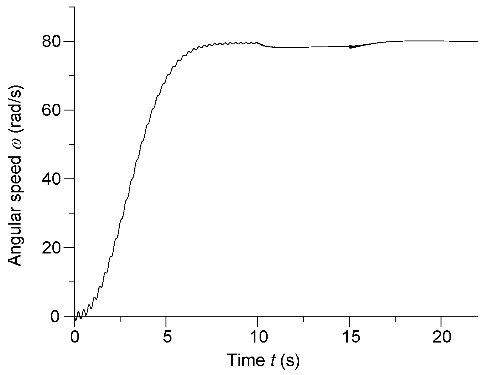
Figure 4 shows the instantaneous angular velocity of the middle part of shafting system no. 3 (see
Figure 2) of the ship’s motion transmission system.
Within the time interval
t ∈ (0;10) s, the analysis of the ship’s propulsion start-up was performed. The input shaft of the gearing was brought to the rotational speed according to the exponential forcing function of the drive engine. When analyzing the physical processes in the long drive shaft, appearing oscillations can be noticed. This indicates the complicated nature of the mechanical wave along the motion transmission system. Once the rotor neared the synchronous speed, a symmetrical resistive-inductive load in a star connection was applied to the generator windings at
t = 10 s. At the same time, the value of the excitation voltage was increased to the rated value. After the appearance of the electric load of the shaft generator, the mechanical load of the drive engine increased, which in turn resulted in a reduction of the rotational speed of the drive shaft by approx. 2%. Then, after the system entered the steady state, a symmetrical three-phase short-circuit condition of the generator occurred at the time
t = 15 s. In the steady short-circuit condition, the generator’s electromagnetic torque decreases almost three to four times, which in turn reduces the load on the drive engine. Under such conditions, it becomes obvious that the rotational speed of the propeller shaft should increase, as shown in
Figure 4.
Figure 5 shows the instantaneous A-phase voltage of the shaft generator.
During the start-up of the ship’s propulsion, the generator armature winding was opened. The shaft generator was accelerating when idle. After reaching the rated voltage, the generator was loaded. In order to maintain the rated value of the armature voltage when the electrical load is applied, the excitation voltage of the generator is increased. At the time t = 10 s, the voltage value at the shaft generator terminals increased by 50%. This voltage step is associated with an increase in the electromotive force (EMF). Consequently, this causes an increase in the generator’s currents and electromagnetic torque. When the generator goes into a short-circuit condition, the voltage at the armature terminals drops to zero.
During the system start-up, the armature winding was open; therefore, the current in the armature winding did not flow (
Figure 6).
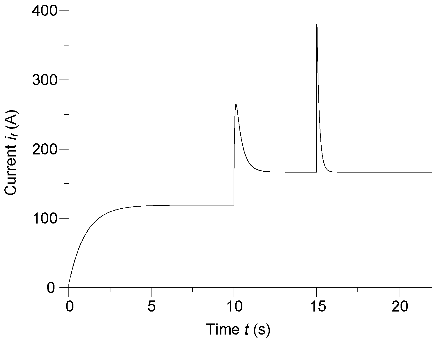
In order to excite a magnetic field in the shaft generator, a current,
if, flows in the excitation winding. Its time course is shown in
Figure 7.
The value of the excitation current was lowered to a value that allowed the generator armature voltage to stabilize at the rated voltage level (see
Figure 5). At the time of loading, the currents in the armature windings increased, and after approx. 2.5 s, they reached their steady-state rated value. A similar situation occurs in the case of the shaft generator excitation current.
A completely different situation occurs in the case of a synchronous generator short-circuit condition in the time t ≥ 15 s. Then, a surge short-circuit current begins to flow in the generator windings, which is very dangerous for the generator. In addition to thermal damage to the insulation of the stator and rotor wires, the surge current also causes mechanical stresses in the generator, which can damage the generator. In such cases, the power-system automation should disconnect the generator from the ship’s electricity network. DC voltage supplying the excitation winding of the generator should also be turned off. After 2.5 s from the generator’s short-circuit beginning, steady short-circuit currents flow in its stator (armature) windings, the value of which is usually about 2–3 times higher than the rated one.
Figure 8 shows the instantaneous flux linkage for the A-phase armature winding of the shaft generator.
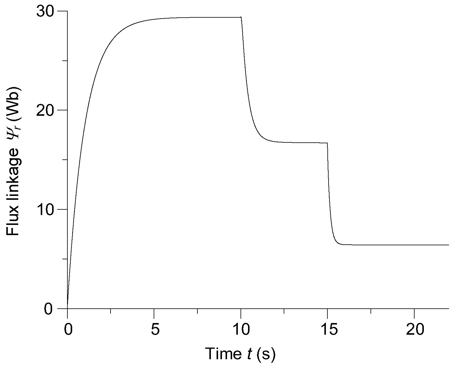
Figure 9 shows the instantaneous flux linkage for the generator excitation winding.
From a scientific point of view, based on the interpretation of the time courses presented in
Figure 8 and
Figure 9, it is possible to determine the nature and time courses of the electromotive forces induced in the armature and rotor windings, because the time derivatives of the analyzed flux linkages according to Faraday’s law represents the induced electromotive forces, i.e., the main energy sources of the shaft generator.
Figure 10 show the instantaneous moments of torsion in the centers of the second and fourth parts of the long drive shaft.
Analyzing
Figure 10 it was noticed that during the system start-up (0 ≤
t ≤ 10 s), the amplitudes of the torsional oscillations of the second part of the long shaft are greater by about 20% compared to the fourth part of the long shaft. The situation is opposite when the shaft generator is operated under load and when the shaft generator is short-circuited. The amplitude of the torsional oscillations of the fourth part of the long shaft is then almost 7 times greater than the amplitude of the oscillation of the second part of the long shaft. This is directly related to the location of the fourth part of the shaft, which is directly in front of the shaft generator and is connected to the propeller.
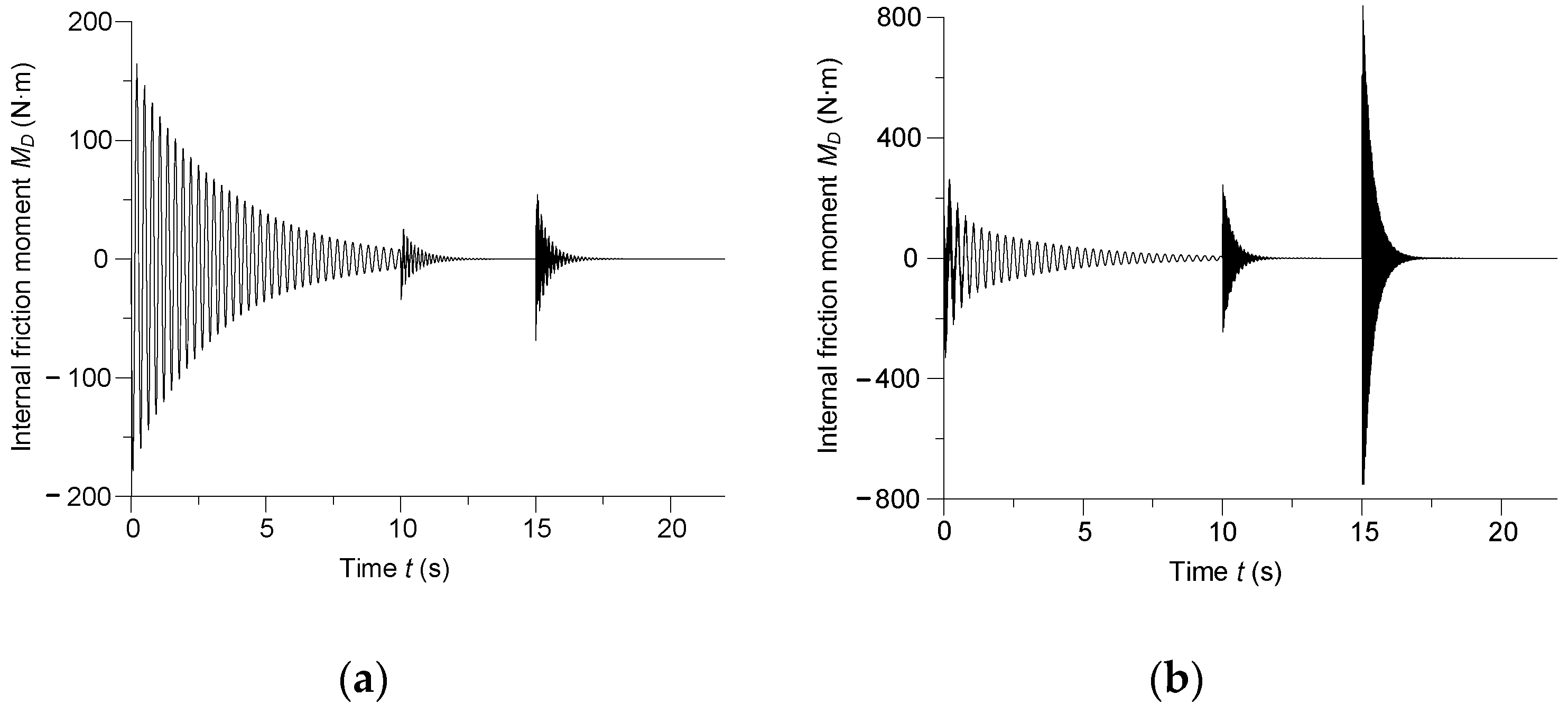
Figure 11 shows the instantaneous internal friction moment in the second and fourth parts of the long shaft transmitting the motion.
The justification for the occurrence of the maximum friction moment in the fourth part of the long drive shaft (
Figure 11) is the same as in the case of the previously described oscillations of torsional moment, shown in
Figure 10.
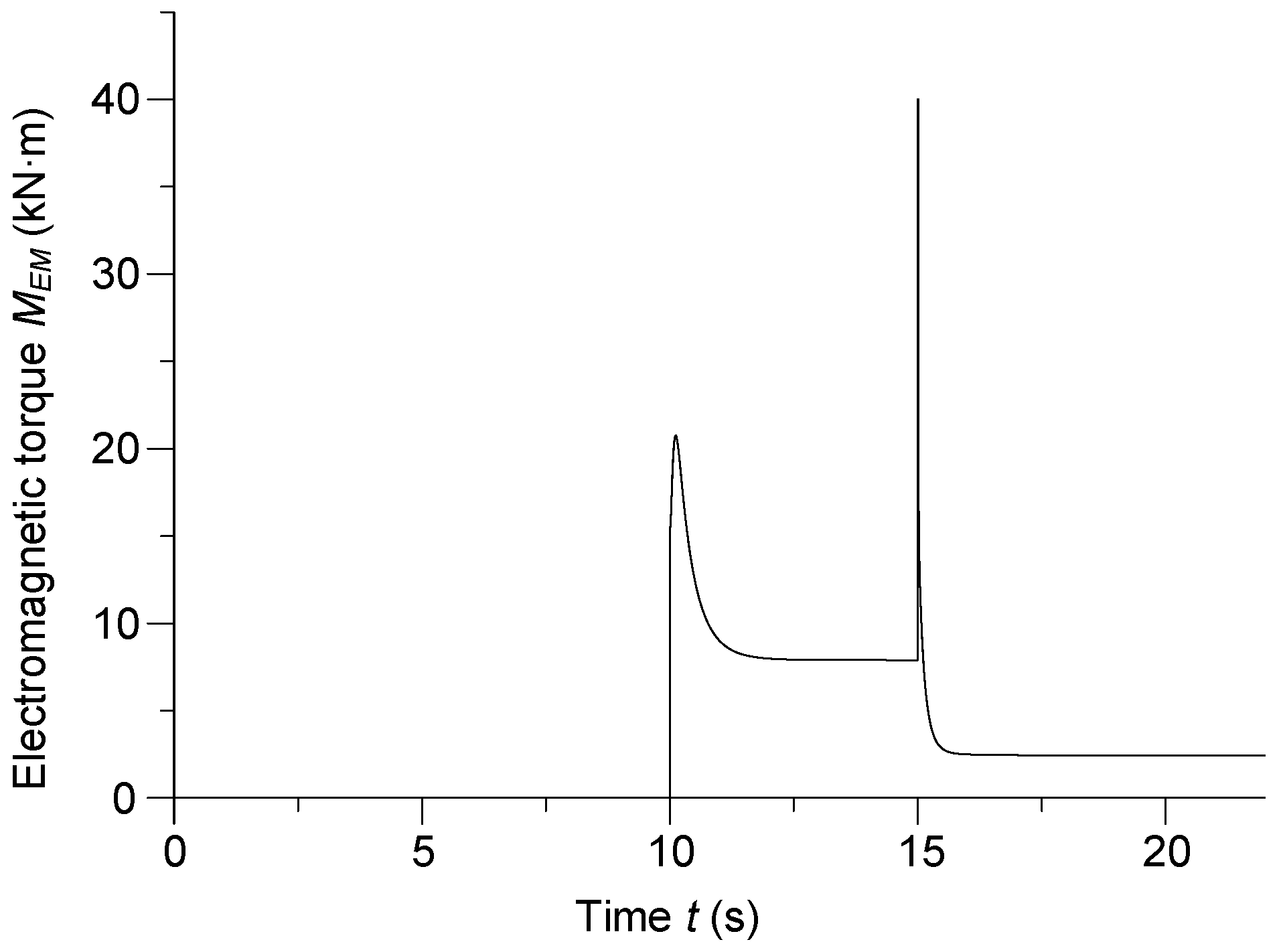
Figure 12 shows the instantaneous electromagnetic torque of the shaft synchronous generator.
Since the electromagnetic torque depends on the currents in the stator windings (see Equation (40)),
Figure 12 should be considered together with
Figure 6. The joint analysis of
Figure 6 and
Figure 12 fully characterizes the principles of electromechanical energy conversion in a shaft generator. At the time of connection of the resistive-inductive load (
t = 10 s), a rapid increase in the torque can be seen, the value of which exponentially decreases to the steady level. Then, at
t = 15 s, a symmetrical three-phase short-circuit of the armature windings takes place. This short-circuit creates a very high impact electromagnetic torque, which also decreases exponentially to a steady level. It should be noted that in the case of conventional generators the described operating state is an emergency. On the other hand, there are enhanced synchronous generators for which the short-circuit condition is not an emergency. These are so-called surge generators. The task of surge generators is to generate a large portion of electromagnetic energy in a short time. Similar phenomena occur during the acceleration of nuclear particles. In the described case, the short-circuit condition is mathematically modeled assuming no trip of the shaft generator protections. The idea of examining the generator short-circuit condition results from the need to analyze the transient states of the ship’s motion transmission.
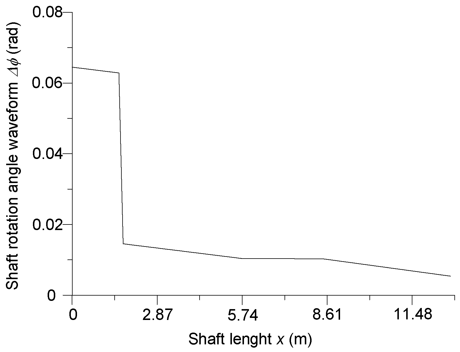
Figure 13 shows the angle of rotation of the long drive shaft as a function of the shaft length during a three-phase symmetrical short circuit of the shaft generator armature windings for 15.1 s.
The angle of rotation shown in
Figure 13 provides information on the torsional moments in individual parts of the long propeller shaft, which, from the point of view of shaft strength, is an important element for the entire motion transmission. When analyzing
Figure 13, it can be seen that the flexible coupling is the most loaded (
x = 1.66 m). The fourth part of the long propeller shaft is also heavily loaded (see
Figure 10b and
Figure 11b). The third part of the long propeller shaft (generator rotor) is characterized by a low twisting load.


