
Friction Factor and Heat Transfer of Giesekus-Fluid-Based Nanofluids in a Pipe Flow


Abstract
:1. Introduction
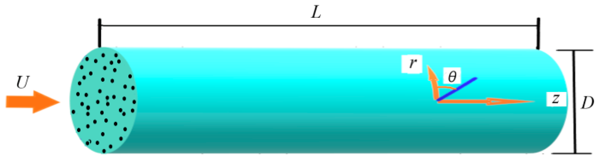
2. Flow and Equations of Nanofluids
3. Equations of Particles
3.1. Dynamics Equation for Nanoparticles
3.2. Moment Equation of Nanoparticles
3.3. Particle Coagulation and Breakage
3.4. Taylor Series Expansion Moment Method
4. Numerical Method
4.1. Steps of Numerical Simulation
4.2. Numerical Method and Boundary Condition
4.3. Parameters
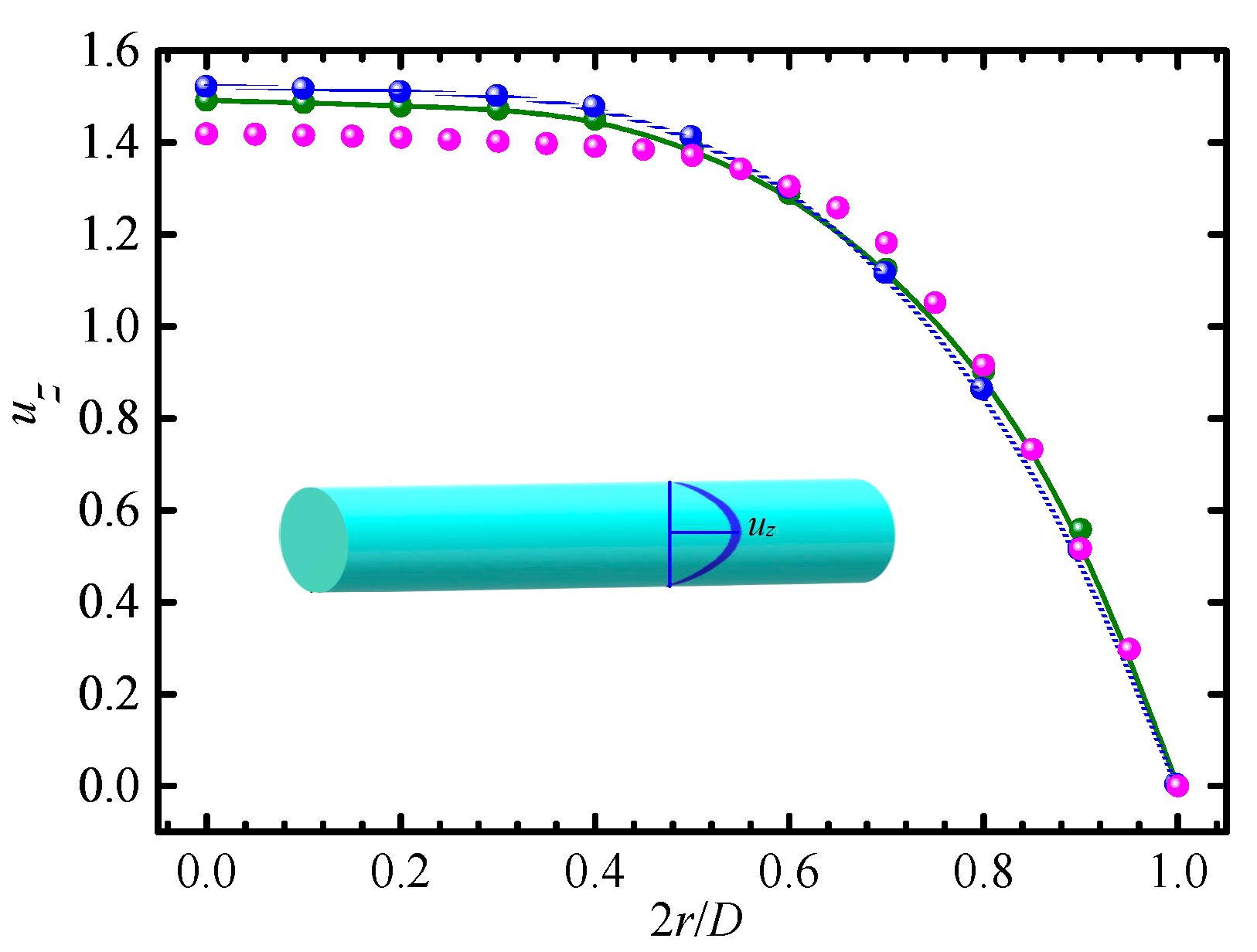
4.4. Validation
5. Results and Discussion
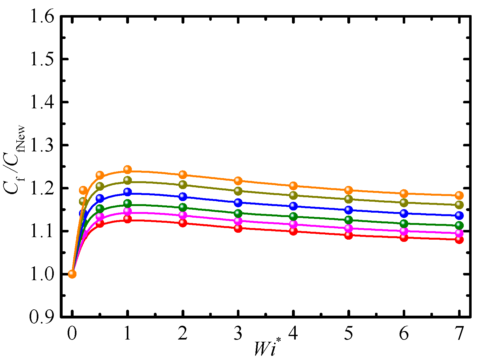
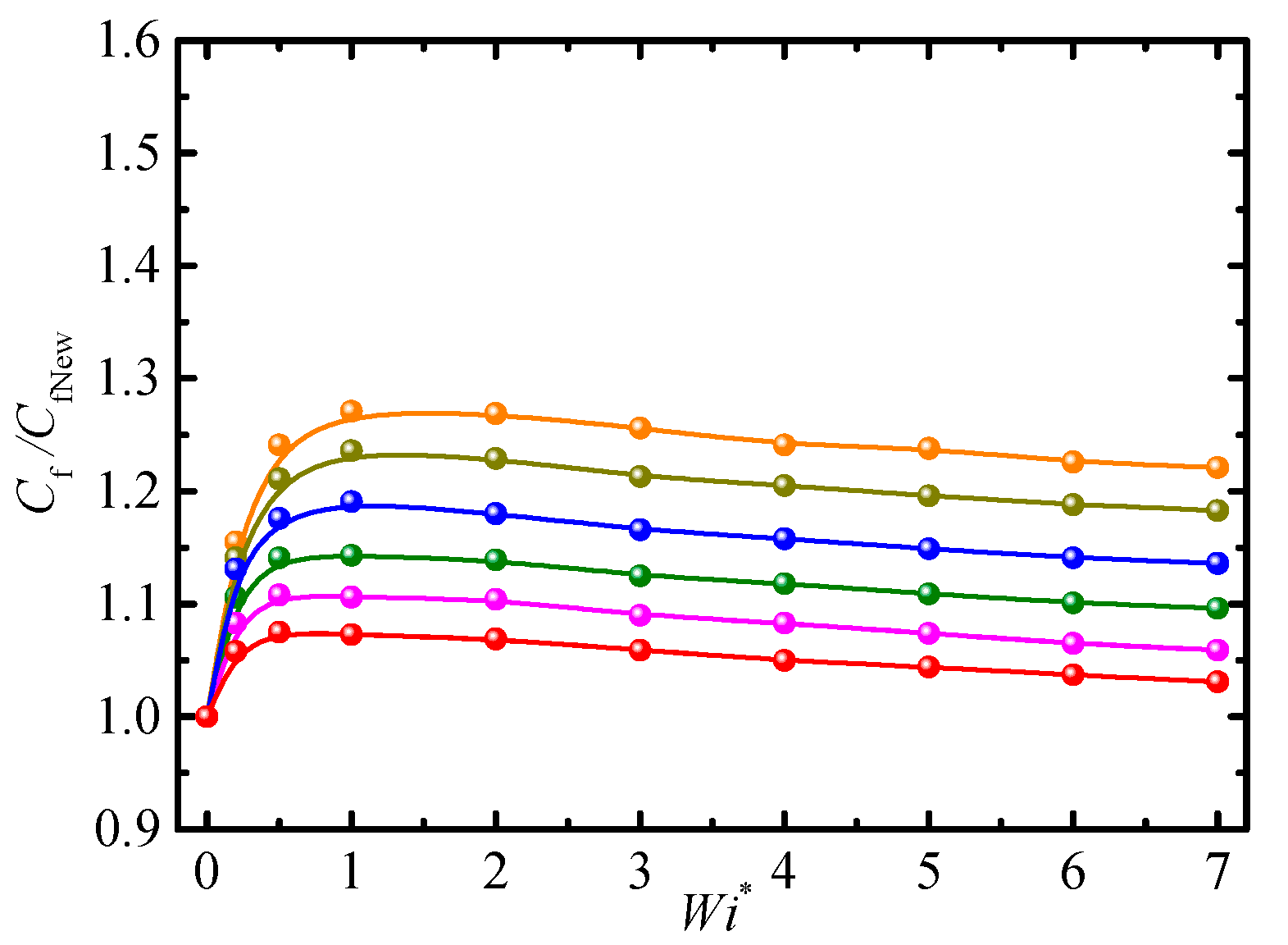
5.1. Friction Factor
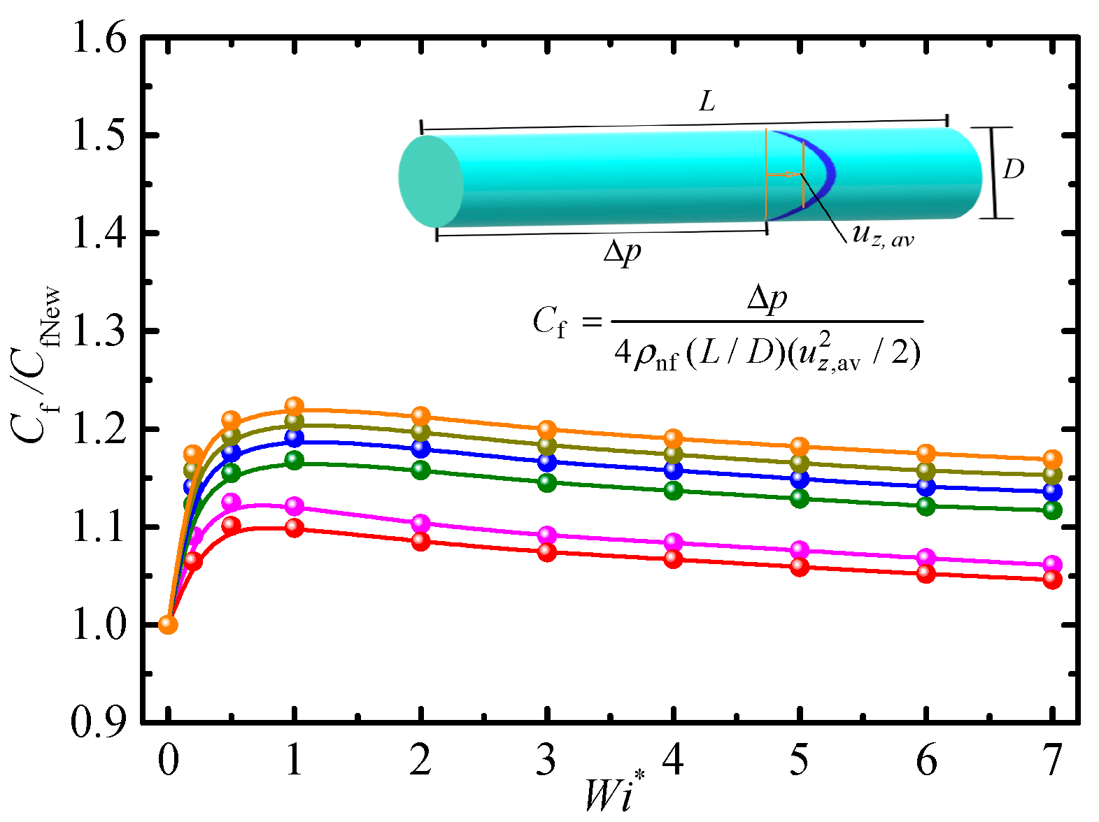
5.1.1. Effect of Weissenberg Number
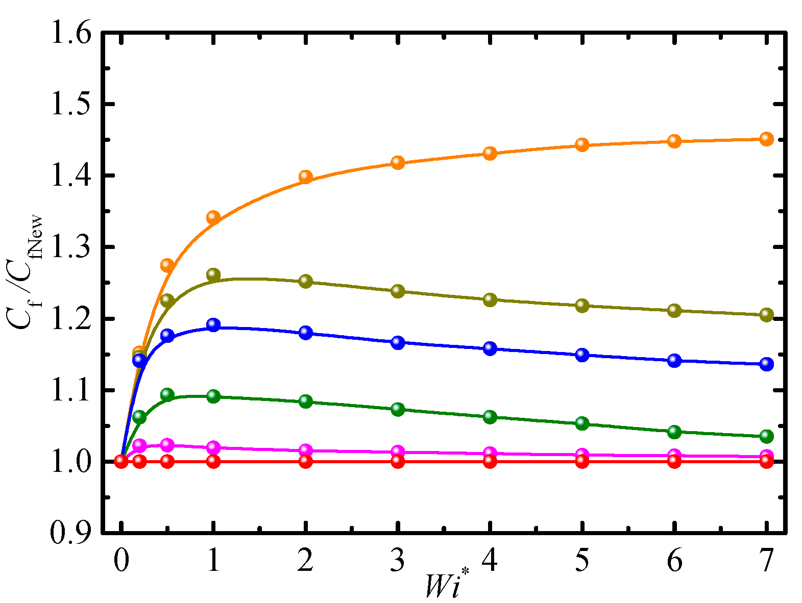
5.1.2. Effects of Particle Concentration and Viscosity Ratio
5.1.3. Effects of Reynolds Number and Mobility Parameter
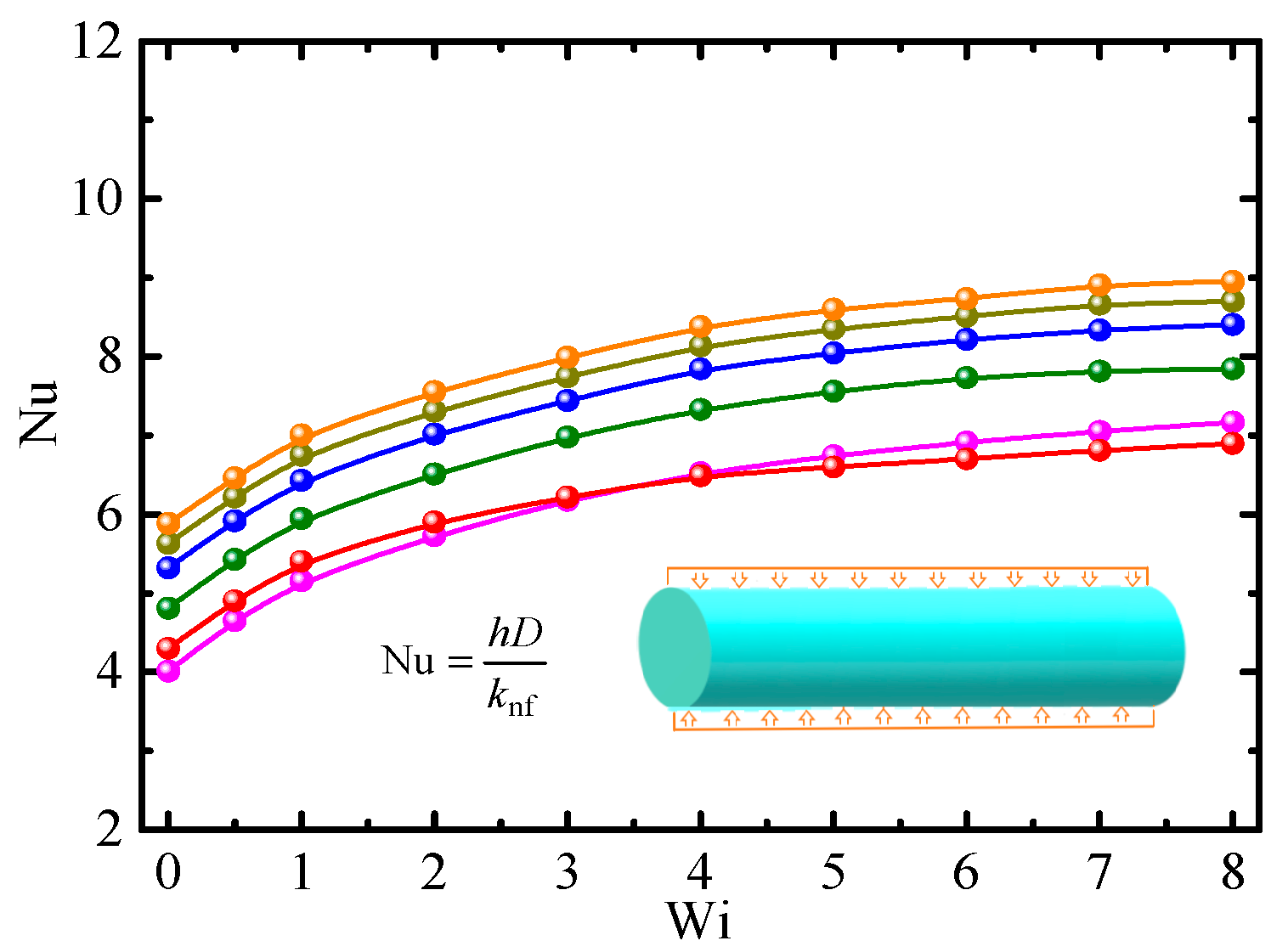
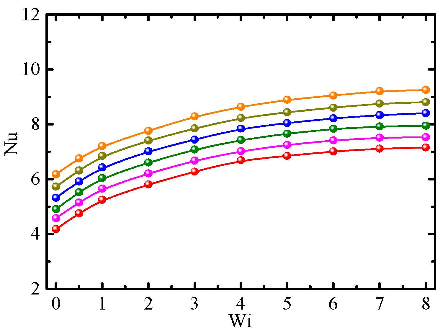
5.2. Heat Transfer
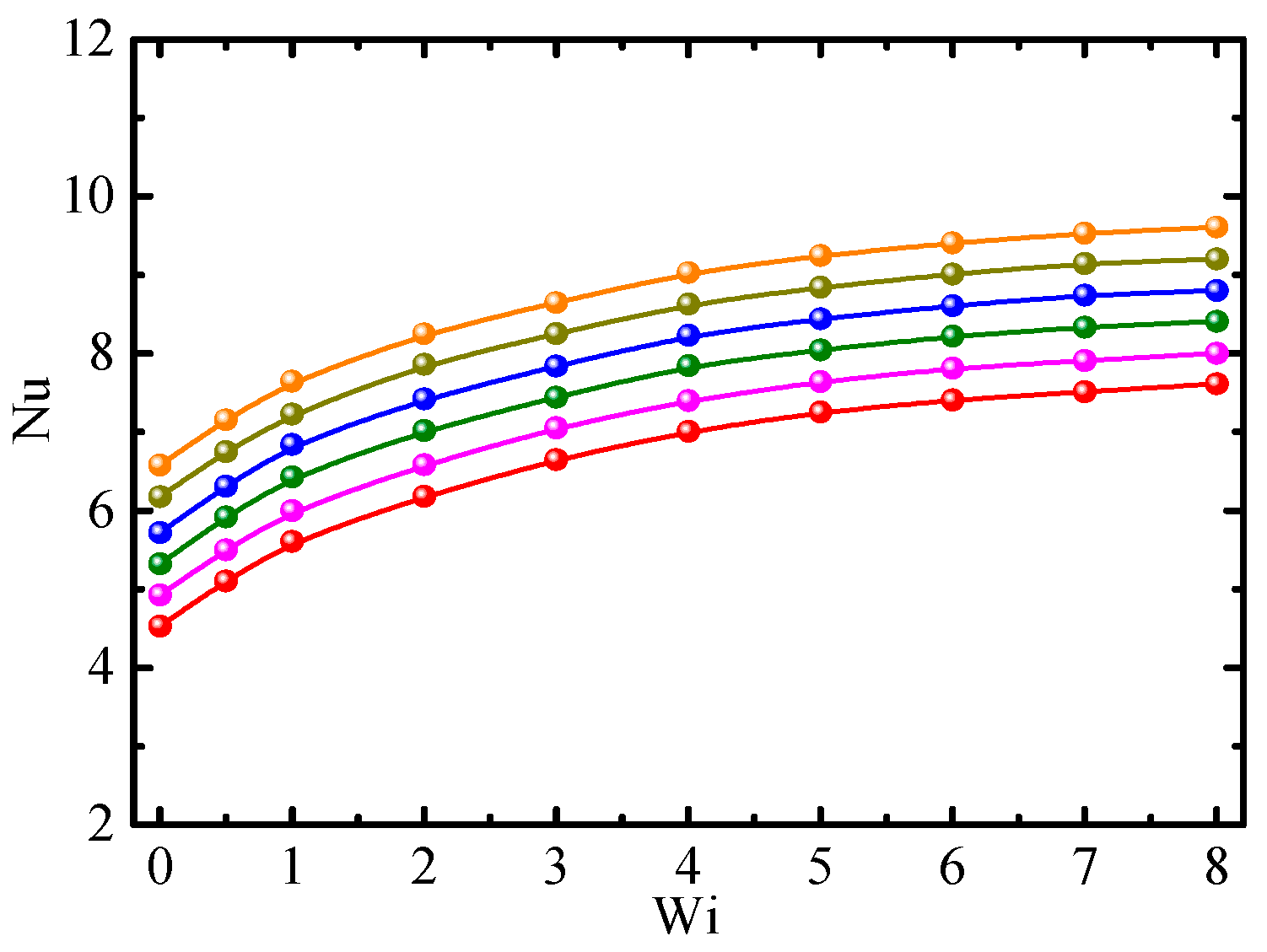
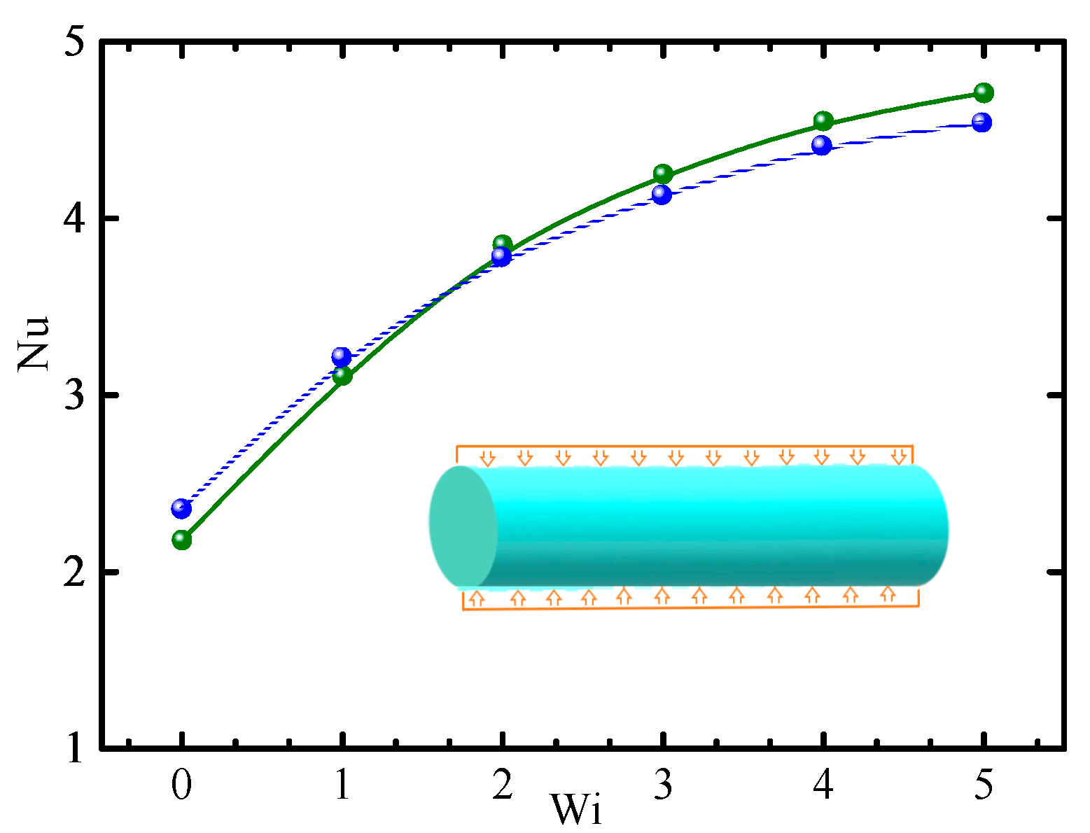
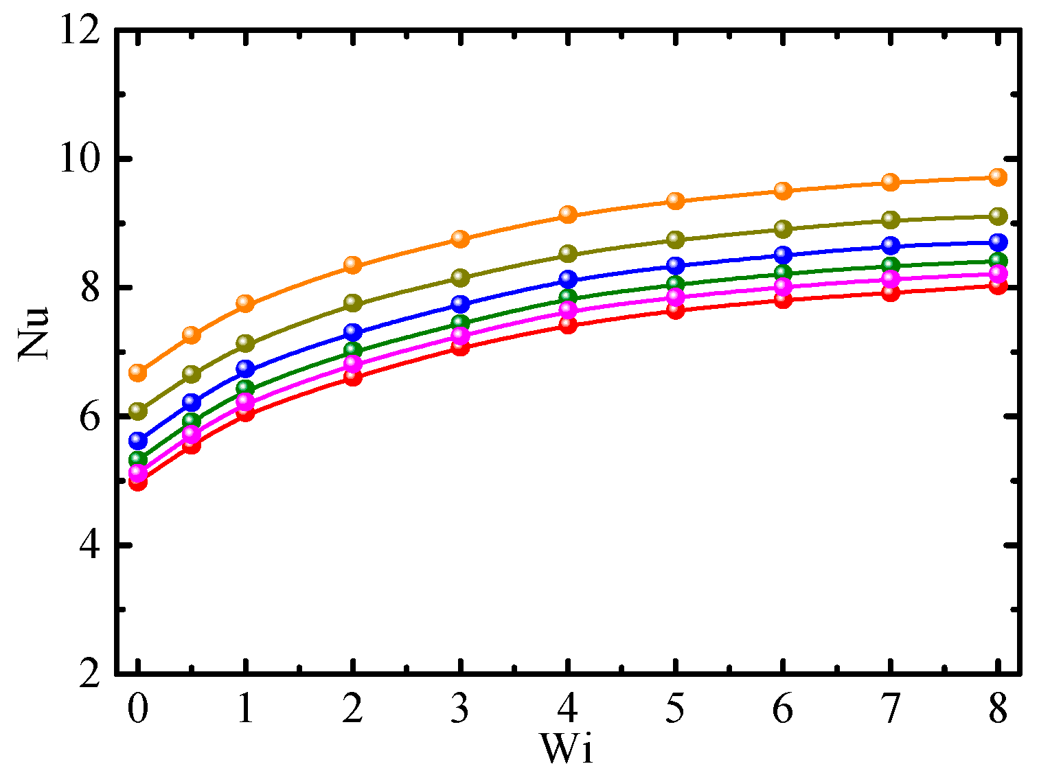
5.2.1. Effect of Weissenberg Number
5.2.2. Effects of Particle Concentration and Viscosity Ratio
5.2.3. Effects of Reynolds Number and Mobility Parameters
5.3. Performance Evaluation Criterion
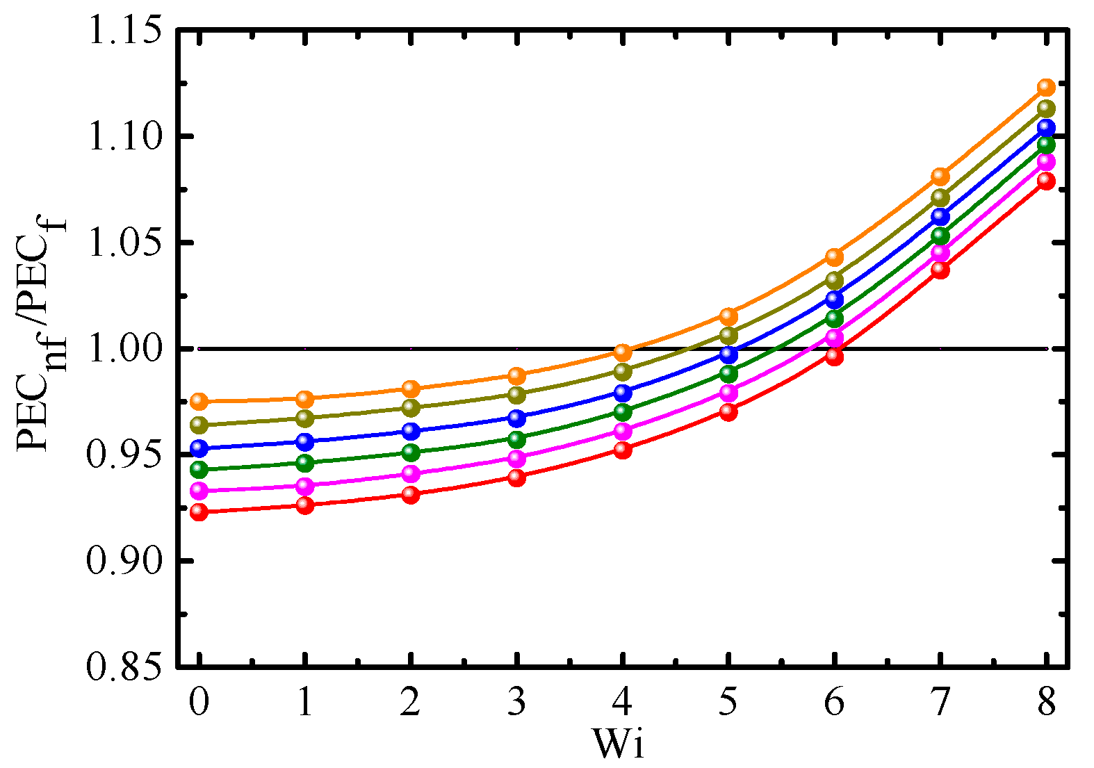
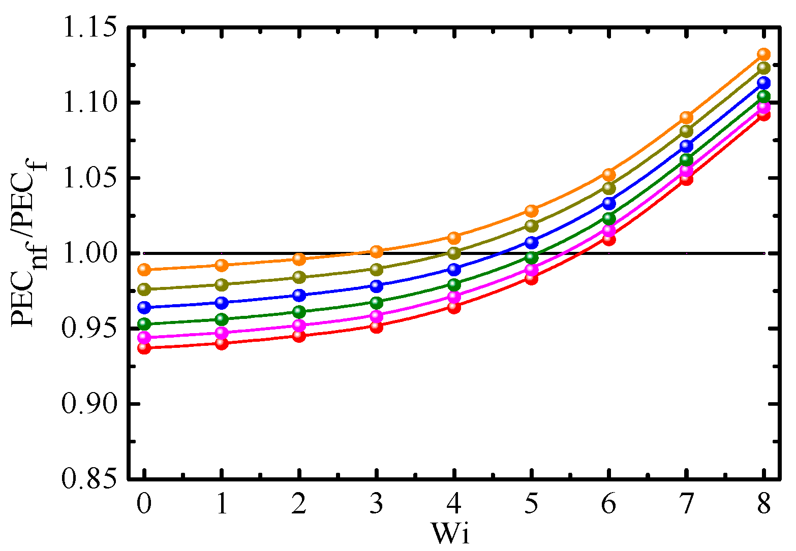
5.3.1. Effects of Various Factors on the PEC
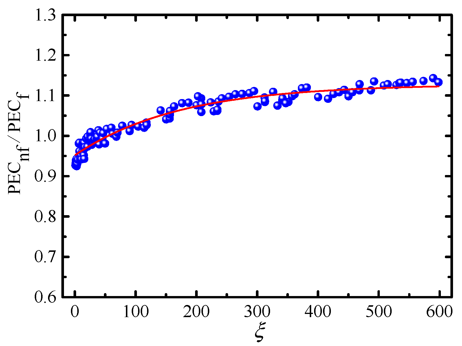
5.3.2. Correlation Model
6. Conclusions
Author Contributions
Funding
Institutional Review Board Statement
Informed Consent Statement
Data Availability Statement
Conflicts of Interest
References
- Cruz, D.A.; Coelho, P.M.; Alves, M.A. A simplified method for calculating heat transfer coefficients and friction factors in laminar pipe flow of non-newtonian fluids. J. Heat Transf. Trans. ASME 2012, 134, 091703. [Google Scholar] [CrossRef]
- Chang, X.; Zhou, J.; Guo, Y.T.; He, S.M.; Wang, L.; Chen, Y.L.; Tang, M.; Jian, R. Heat transfer behaviors in horizontal wells considering the effects of drill pipe rotation, and hydraulic and mechanical frictions during drilling procedures. Energies 2018, 11, 2414. [Google Scholar] [CrossRef] [Green Version]
- Martorana, P.; Bayer, I.S.; Steele, A.; Loth, E. Effect of graphite and carbon nanofiber additives on the performance efficiency of a gear pump driven hydraulic circuit using ethanol. Ind. Eng. Chem. Res. 2010, 49, 11363–11368. [Google Scholar] [CrossRef]
- Peng, Y.P.; Zahedidastjerdi, A.; Abdollahi, A.; Amindoust, A.; Bahrami, M.; Karimipour, A.; Goodarzi, M. Investigation of energy performance in a u-shaped evacuated solar tube collector using oxide added nano-particles through the emitter, absorber and transmittal environments via discrete ordinates radiation method. J. Therm. Anal. Calorim. 2020, 139, 2623–2631. [Google Scholar] [CrossRef]
- Tian, Z.; Abdollahi, A.; Shariati, M.; Amindoust, A.; Arasteh, H.; Karimipour, A.; Goodarzi, M.; Bach, Q.V. Turbulent flows in a spiral double-pipe heat exchanger optimal performance conditions using an enhanced genetic algorithm. Int. J. Numer. Methods Heat Fluid Flow 2020, 30, 39–53. [Google Scholar] [CrossRef]
- Sandeep, N.; Malvandi, A. Enhanced heat transfer in liquid thin film flow of non-newtonian nanofluids embedded with graphene nanoparticles. Adv. Powder Technol. 2016, 27, 2448–2456. [Google Scholar] [CrossRef]
- Sulaiman, M.; Ali, A.; Islam, S. Heat and mass transfer in three-dimensional flow of an Oldroyd-B nanofluid with gyrotactic micro-organisms. Math. Probl. Eng. 2018, 2018, 6790420. [Google Scholar] [CrossRef] [Green Version]
- Sandeep, N.; Sulochana, C. Momentum and heat transfer behavior of Jeffrey, Maxwell and Oldroyd-B nanofluids past a stretching surface with non-uniform heat source/sink. Ain Shams Eng. J. 2018, 9, 517–524. [Google Scholar] [CrossRef] [Green Version]
- Aziz, A.; Muhammad, T.; Alsaedi, A.; Hayat, T. An optimal study for 3D rotating flow of Oldroyd-B nanofluid with convectively heated surface. J. Braz. Soc. Mech. Sci. Eng. 2019, 41, 236. [Google Scholar] [CrossRef]
- Berberovic, E.; Bikic, S. Computational study of flow and heat transfer characteristics of EG-Si3N4 nanofluid in laminar flow in a pipe in forced convection regime. Energies 2020, 13, 74. [Google Scholar] [CrossRef] [Green Version]
- Sandeep, N.; Kumar, B.R.; Kumar, M.S.J. A comparative study of convective heat and mass transfer in non-Newtonian nanofluid flow past a permeable stretching sheet. J. Mol. Liq. 2015, 212, 585–591. [Google Scholar] [CrossRef]
- Shaikh, S.; Lafdi, K.; Ponnappan, R. Thermal conductivity improvement in Carbon nanoparticle doped PAO oil: An experimental study. J. Appl. Phys. 2007, 101, 064302. [Google Scholar] [CrossRef] [Green Version]
- Nelson, I.C.; Banerjee, D.; Ponnappan, R. Flow loop experiments using polyalphaolefin nanofluids. J. Heat Transf. 2009, 23, 752–761. [Google Scholar] [CrossRef]
- Yu, L.; Liu, D.; Botz, F. laminar convective heat transfer of alumina-polyalphaolefin nanofluids containing spherical and non-spherical nanoparticles. Exp. Therm. Fluid Sci. 2012, 37, 72–83. [Google Scholar] [CrossRef]
- Yang, J.C.; Li, F.C.; Cai, W.H.; Zhang, H.N.; Yu, B. Direct numerical simulation of viscoelastic-fluid-based nanofluid turbulent channel flow with heat transfer. Chin. Phys. B 2015, 24, 084401. [Google Scholar] [CrossRef]
- Wang, Y.; Wang, Y.; Cheng, Z. Direct numerical simulation of gas-liquid drag-reducing cavity flow by the voset method. Polymer 2019, 11, 596. [Google Scholar] [CrossRef] [Green Version]
- D’Avino, G.; Maffettone, L. Particle dynamics in viscoelastic liquids. J. Non-Newton. Fluid Mech. 2015, 215, 80–104. [Google Scholar] [CrossRef]
- Batchelor, G.K. The Effect of brownian motion on the bulk stress in a suspension of spherical particles. J. Fluid Mech. 1977, 83, 97–117. [Google Scholar] [CrossRef]
- Zhang, X.; Gu, H.; Fujii, M. Effective thermal conductivity and thermal diffusivity of nanofluids containing spherical and cylindrical nanoparticles. Exp. Therm. Fluid Sci. 2007, 31, 593–599. [Google Scholar] [CrossRef]
- Barrett, J.C.; Webb, N.A. A Comparison of some approximate methods for solving the aerosol general dynamic equation. J. Aerosol Sci. 1998, 29, 31–39. [Google Scholar] [CrossRef]
- Barthelmes, G.; Pratsinis, S.E.; Buggisch, H. Particle size distributions and viscosity of suspensions undergoing shear-induced coagulation and fragmentation. Chem. Eng. Sci. 2003, 58, 2893–2902. [Google Scholar] [CrossRef]
- Marchisio, D.L.; Vigil, R.D.; Fox, R.O. Implementation of the quadrature method of moments in CFD codes for aggregation-breakage problems. Chem. Eng. Sci. 2003, 58, 3337–3351. [Google Scholar] [CrossRef]
- Yu, M.Z.; Lin, J.Z.; Chan, T.L. A new moment method for solving the coagulation equation for particles in brownian motion. Aerosol Sci. Technol. 2008, 42, 705–713. [Google Scholar] [CrossRef]
- Yu, M.Z.; Lin, J.Z. Binary homogeneous nucleation and growth of water-sulfuric acid nanoparticles using a TEMOM model. Int. J. Heat Mass Transf. 2010, 53, 635–644. [Google Scholar] [CrossRef]
- Vachagina, E.; Dushin, N.; Kutuzova, E.; Kadyirov, A. Exact solution for viscoelastic flow in pipe and experimental validation. Polymers 2022, 14, 334. [Google Scholar] [CrossRef]
- Khatibi, A.M.; Mirzazadeh, M.; Rashidi, F. Forced convection heat transfer of Giesekus viscoelastic fluid in pipes and channels. Heat Mass Transf. 2010, 46, 405–412. [Google Scholar] [CrossRef]
- Housiadas, K.D.; Beris, A.N. On the skin friction coeffificient in viscoelastic wall-bounded flows. Int. J. Heat Fluid Flow 2013, 42, 49–67. [Google Scholar] [CrossRef]
- Bao, F.B.; Lin, J.Z. Burnett simulation of gas flow and heat transfer in micro Poiseuille flow. Int. J. Heat Mass Transf. 2008, 51, 4139–4144. [Google Scholar] [CrossRef]
- Azmi, W.H.; Sharma, K.V.; Sarma, P.K.; Septiadi, W.N. Experimental determination of turbulent forced convection heat transfer and friction factor with SiO2 nanofluid. Exp. Therm. Fluid Sci. 2013, 51, 103–111. [Google Scholar] [CrossRef] [Green Version]
- Lin, J.Z.; Xia, Y.; Ku, X.K. Pressure drop and heat transfer of nanofluid in turbulent pipe flow considering particle coagulation and breakage. J. Heat Transf. 2014, 136, 111701. [Google Scholar] [CrossRef]
- Zhang, P.J.; Lin, J.Z.; Ku, X.K. Friction factor and heat transfer of nanofluid in the turbulent flow through a 90° bend. J. Hydrodyn. 2021, 33, 1105–1118. [Google Scholar] [CrossRef]
- Melhi, S.A.; Filali, A.; Khezzar, L.; Alshehhi, M. Flow and heat transfer of a Giesekus fluid in plane and 3D ducts. Heat Transf.-Asian Res. 2017, 46, 1380–1398. [Google Scholar] [CrossRef]
- Abbasian Arani, A.A.; Amani, J. Experimental investigation of diameter effect on heat transfer performance and pressure drop of TiO2–water nanoflfluid. Exp. Therm. Fluid Sci. 2013, 44, 520–533. [Google Scholar] [CrossRef]
- Khezzar, L.; Filali, A.; AlShehhi, A.M. Flow and heat transfer of FENE-P fluids in ducts of various shapes: Effffect of Newtonian solvent contribution. J. Non-Newton Fluid. 2014, 207, 7–20. [Google Scholar] [CrossRef]
- Ferrouillat, S.; Bontemps, A.; Poncelet, O.; Soriano, O.; Gruss, J.A. Inflfluence of nanoparticle shape factor on convective heat transfer and energetic performance of water-based SiO2 and ZnO nanoflfluids. Appl. Therm. Eng. 2013, 51, 839–851. [Google Scholar] [CrossRef]


| r × θ × S | M0 | r × θ × S | M0 | r × θ × S | M0 |
|---|---|---|---|---|---|
| 112 × 32 × 256 | 1.08669 | 128 × 24 × 256 | 1.08664 | 128 × 32 × 216 | 1.08660 |
| 120 × 32 × 256 | 1.08651 | 128 × 28 × 256 | 1.08648 | 128 × 32 × 236 | 1.08647 |
| 128 × 32 × 256 | 1.08636 | 128 × 32 × 256 | 1.08636 | 128 × 32 × 256 | 1.08636 |
| 136 × 32 × 256 | 1.08628 | 128 × 36 × 256 | 1.08630 | 128 × 32 × 276 | 1.08631 |
| 144 × 32 × 256 | 1.08622 | 128 × 40 × 256 | 1.08626 | 128 × 32 × 296 | 1.08628 |
Publisher’s Note: MDPI stays neutral with regard to jurisdictional claims in published maps and institutional affiliations. |
© 2022 by the authors. Licensee MDPI, Basel, Switzerland. This article is an open access article distributed under the terms and conditions of the Creative Commons Attribution (CC BY) license (https://creativecommons.org/licenses/by/4.0/).
Share and Cite
Lin, W.; Yang, H.; Lin, J. Friction Factor and Heat Transfer of Giesekus-Fluid-Based Nanofluids in a Pipe Flow. Energies 2022, 15, 3234. https://doi.org/10.3390/en15093234
Lin W, Yang H, Lin J. Friction Factor and Heat Transfer of Giesekus-Fluid-Based Nanofluids in a Pipe Flow. Energies. 2022; 15(9):3234. https://doi.org/10.3390/en15093234
Chicago/Turabian StyleLin, Wenqian, Hailin Yang, and Jianzhong Lin. 2022. "Friction Factor and Heat Transfer of Giesekus-Fluid-Based Nanofluids in a Pipe Flow" Energies 15, no. 9: 3234. https://doi.org/10.3390/en15093234
APA StyleLin, W., Yang, H., & Lin, J. (2022). Friction Factor and Heat Transfer of Giesekus-Fluid-Based Nanofluids in a Pipe Flow. Energies, 15(9), 3234. https://doi.org/10.3390/en15093234