Review

A Review of the Impact of Hydrogen Integration in Natural Gas Distribution Networks and Electric Smart Grids

1
Instituto Superior Técnico, University of Lisbon, 1049-001 Lisboa, Portugal
2
INESC-ID/IST, University of Lisbon, 1000-029 Lisboa, Portugal
3
SustainRD, EST Setúbal, Polytechnic Institute of Setubal, 2914-508 Setubal, Portugal
4
Centre of Technology and Systems (CTS-UNINOVA), 2829-516 Caparica, Portugal
*
Author to whom correspondence should be addressed.
Energies 2022, 15(9), 3160; https://doi.org/10.3390/en15093160
Submission received: 28 March 2022 / Revised: 19 April 2022 / Accepted: 21 April 2022 / Published: 26 April 2022

Abstract

:
Hydrogen technologies have been rapidly developing in the past few decades, pushed by governments’ road maps for sustainability and supported by a widespread need to decarbonize the global energy sector. Recent scientific progress has led to better performances and higher efficiencies of hydrogen-related technologies, so much so that their future economic viability is now rarely called into question. This article intends to study the integration of hydrogen systems in both gas and electric distribution networks. A preliminary analysis of hydrogen’s physical storage methods is given, considering both the advantages and disadvantages of each one. After examining the preeminent ways of physically storing hydrogen, this paper then contemplates two primary means of using it: integrating it in Power-to-Gas networks and utilizing it in Power-to-Power smart grids. In the former, the primary objective is the total replacement of natural gas with hydrogen through progressive blending procedures, from the transmission pipeline to the domestic burner; in the latter, the set goal is the expansion of the implementation of hydrogen systems—namely storage—in multi-microgrid networks, thus helping to decarbonize the electricity sector and reducing the impact of renewable energy’s intermittence through Demand Side Management strategies. The study concludes that hydrogen is assumed to be an energy vector that is inextricable from the necessary transition to a cleaner, more efficient, and sustainable future.

1. Introduction

Hydrogen-related technologies have been through many cycles of expectations over the past few decades. Nowadays, a growing body of evidence finally suggests the soon-to-be end of these cycles, with hydrogen standing as an attractive alternative—some even say, an indispensable option—for the deep decarbonization needed by our global energy system [1]. This scenario is further supported by recent scientific improvements that considerably reduced costs and increased the performance of hydrogen-related technologies, to a point where its economic viability is no longer discussed.
To speak about the development of the hydrogen economy is to first discuss the strategic configurations on its value chain. Nowadays, most hydrogen (H 2 ) road maps put forward by governments around the world recognize hydrogen as an exceptionally versatile energy vector, with several possible applications in all main sectors of modernized societies—industry, buildings, transportation, and of course, energy [2]. Figure 1 presents a general diagram of the value chain usually associated with hydrogen, showing that to proceed with its implementation, a definition of the possible strategic configurations (from production to end-use) must first be made.
Today, there are several different methods of producing green hydrogen from renewable energy sources, ranging from thermochemical to biological (biomass) processes, and naturally, water splitting—with electrolysis being the most well-known and established of them all. Shiva Kumar and Himabindu [4] have comprehensively reviewed the various hydrogen production methods along with their advantages, disadvantages, efficiencies, and costs; they focused mainly on alkaline water electrolysis, proton-exchange membrane electrolysis, and solid oxide electrolysis, with the last still being in the research and first-trials phase. Barbir [5] deeply studied the applications of proton exchange membrane electrolysis, particularly accessing the various possibilities from an end-user point-of-view. Hydrogen that is centrally produced using photovoltaic-generated electricity from solar parks could be used directly as a fuel or transmitted through the pipelines to the consumers, based on approaches such as grid-independent or grid-assisted solar hydrogen generation.
Schmidt et al. [6] performed an extensive expert elicitation study that analyzed the future cost and performance of water electrolysis technologies while addressing the methods mentioned above. The authors found that most experts believe that leading up to 2030, a trend favoring proton-exchange membranes over alkaline electrolysers will be established. Solid oxide electrolysis is still viewed with some uncertainty despite being the preferred method of some experts. The study goes on to determine whether production scale-up or increased R&D funding is seen as having more impact on capital cost reduction; it later concludes that the lowest costs and the highest performances can be obtained in conditions where both strategies are combined—therefore recommending broad deployment policies for all water electrolysis technologies.
Hence, following hydrogen’s value chain flowchart, once it is produced, it has to be transported to storage facilities to then be distributed and used. Moradi and Groth [7] wrote an interesting article regarding hydrogen storage and delivery, where they performed a risk and reliability analysis of distinct hydrogen systems. They started by plainly describing hydrogen’s different storage technologies, dividing them into physical and material methods; while the former encompasses compressed gas, liquid, and cryo-compressed gaseous hydrogen, the latter subdivides it into chemisorption and physisorption (each one of them comprising several different sub-methods). The conclusions of the study naturally concern the different technologies’ maturity, efficiency, reliability, and economic viability linked to the final application. This highlights the relevance such research has for the development of hydrogen integration in modern societies, namely through the implementation of strategic configurations such as the decarbonization of natural gas networks and the electric grid.
Thus, this paper intends to carry out a focused review of such integration of hydrogen systems in distribution networks—both gas and electric—while addressing the literature published on this matter. It does so initially by performing an extensive analysis of current principal methods of physical hydrogen storage, evaluating their main advantages, disadvantages, and characteristics. Concerning hydrogen blending in the natural gas infrastructure, the sensitivity of several constituent parts of any common gas supply chain is addressed, from transmission structures to the end-user; on its integration into the electric grid (particularly smart grids), a study is conducted based on applications with a power-to-power strategic configuration: both in distributed microgrids and within a broader framework such as the hydrogen economy, including demand side management.
This paper structures and frames the possible impacts of the integration of hydrogen systems into general gas and electricity networks, reflexively and critically; to the authors’ best knowledge, no such work has been published before, further accrediting the innovation of this article.
The remainder of the manuscript is arranged as follows: Section 2 offers a comprehensive review of the current leading methods for physically storing hydrogen, from compressed gas to liquid and cryo-compressed gas. Section 3 delivers an in-depth analysis of hydrogen integration in gas networks, following a power-to-gas strategic configuration and accessing the various aspects of such networks in terms of their hydrogen blending tolerance. Section 4, in turn, focuses on studying the implementation of hydrogen systems in power-to-power smart grids, especially stand-alone microgrids and grid-tied multi-microgrids. Finally, some conclusions are provided in Section 5, where possible future work is likewise suggested.

2. Hydrogen Storage Technologies

Storage is an essential topic when it comes to hydrogen integration in distribution networks and large-scale applications; the existence of a robust and reliable way of storing this energy vector is crucial to addressing the current potential demand for hydrogen in the energy market.
As mentioned above, many forms of storage have been developed, which could mainly be divided into Physical-based and Material-based approaches. Physical storage includes compressed gas, liquid, and cryo-compressed hydrogen, and it is the most widely used storage type from among these systems. The following is a more in-depth explanation of each one of these methods.

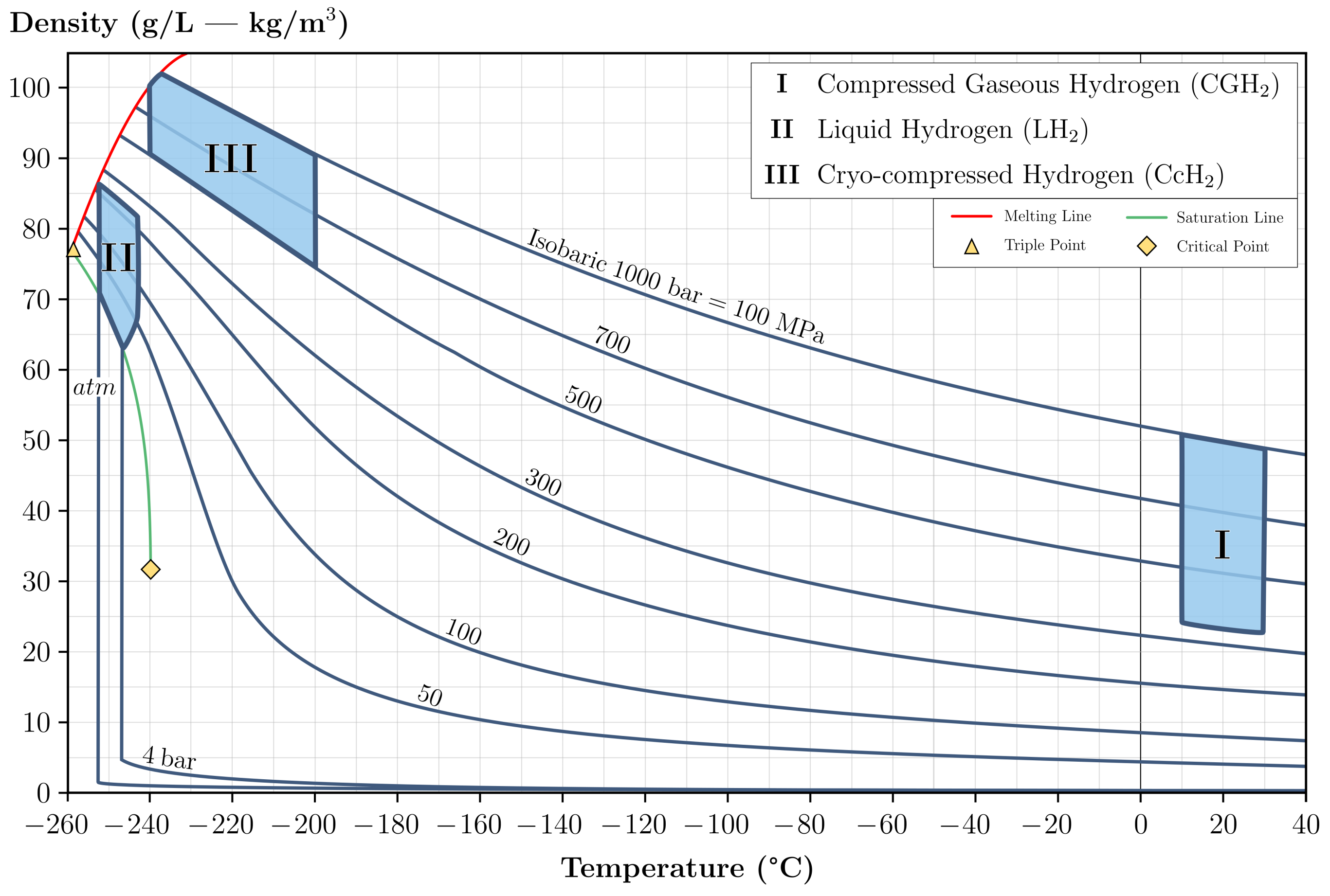
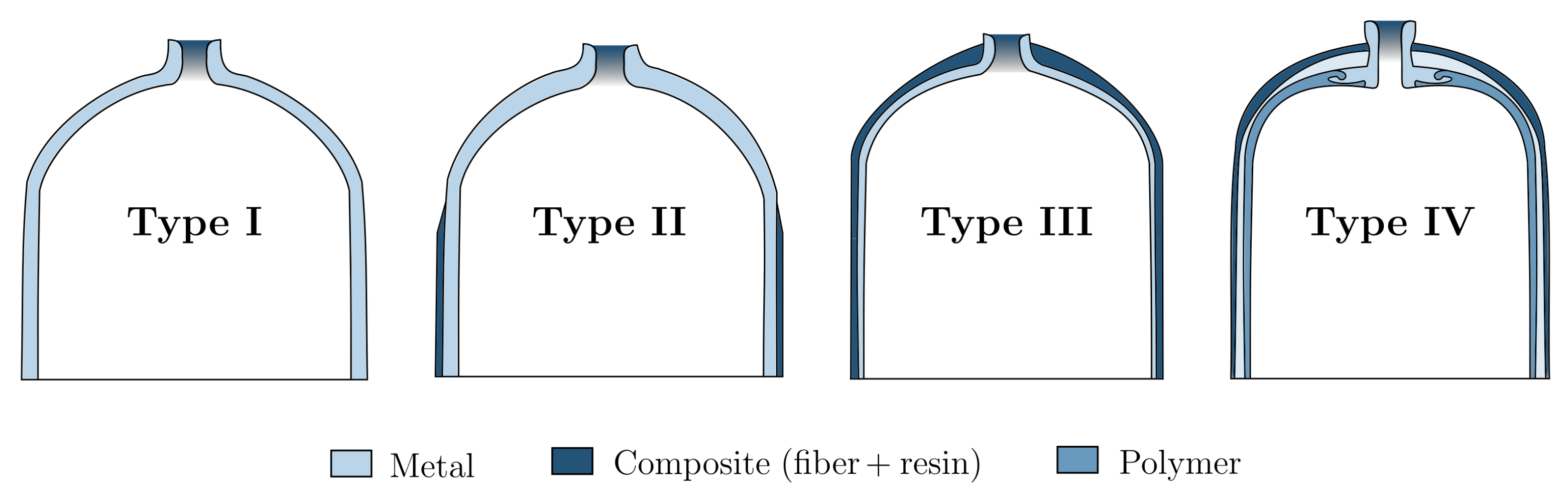
2.1. Compressed Gaseous Hydrogen

Compressing hydrogen gas (CGH 2 ) in order to store it is not a new idea; in fact, in 1880, hydrogen was already stored for military use at pressures of 12 MPa. It was not until the 1960s—when the military and aerospace industries developed high-pressure composite vessels (made of aluminum with a polymer liner and fiberglass wrapping)—that tanks capable of withstanding much higher pressures were developed. In 1970, breathable apparel for firemen was introduced, and in the following decade, pressure vessels were used for the first time in professional diving and in other applications such as recreation paintball. Nowadays, hydrogen storage tanks’ pressures range from 35 MPa to 100 MPa and are already used in fuel cell electric vehicles.
Moradi and Groth [7] presented tanks in four different types of pressure vessels, as shown in Figure 2, to be used for hydrogen storage.
Each differs in the maximum allowable pressure, the materials used, and the overall design as well as in cost (and consequently, in market share). Choosing what type of tank to use is primarily based on the final application, usually requiring a compromise amidst technical performances and cost competitiveness.
Type I tanks are fully metallic, mainly aluminum or steel, thus being the cheapest—and hence the most used for industrial hydrogen storage; it is also the heaviest (about 1.50 kg per liter of hydrogen), and pressures inside can reach up to 50 MPa. Type II vessels are made of thinner steel walls but have a fiberglass composite over-wrap—ensuring one of the highest pressure tolerances and allowing a reduction of about 40% in weight when compared to Type I tanks. Its design provides a structural load distribution equally divided between the steel and the composite parts, but which leads to a 50% increase in the manufacturing price. It is mainly used for stationary applications. Type III and Type IV vessels are planned for mobile applications, in which weight performance is essentially optimized; however, they are much more expensive. Type III are full composite-wrap tanks with just a metal liner for sealing purposes; the structural load is mainly carried by the carbon fiber composite and can safely withstand maximum pressures of around 45 MPa. This type of vessel has much better weight performance than the previous ones, weighing about 0.40 kg per liter of hydrogen but at double the cost. Finally, Type IV vessels usually have a high-density polyethylene plastic for the liner and a carbon-fiber/carbon-glass material for the structure. This vessel can hold pressures as high as 100 MPa while being the lightest among all four types—but it is also the most expensive.
M. Legault [9] wrote about an additional fifth stage, which has been studied for more than a decade now and aims to be a true fully composite pressure vessel. Composites Technology Development, Inc. (Lafayette, Colorado, USA) have successfully designed, tested, and built such a tank for a real-world application, with its main advantage being its extremely low weight: it is 20% lighter than a Type IV tank. However, as Barthelemy et al. [8] stated, since its operational pressure is only 1.37 MPa, it is deemed unsuitable to withstand current pressures needed to store enough amounts of hydrogen outside of a laboratory.
A summary of these vessels’ characteristics is given in Table 1.
As mentioned above, the design of such vessels must take into account several aspects, including service pressure, the external mechanical stresses or impacts they are subjected to, their lifecycle and lifetime, and their safety coefficient requirements for both static and dynamic situations. In general, all metallic parts are usually made of aluminum 6061/7060 or steel inox, and all polymer parts mainly make use of polyethylene or polyamide-based materials. The composites’ components are commonly a mix of glass, aramid, or carbon fiber and a resin, which can be polyester, phenol, or epoxy (the latter being preferred for its greater mechanical properties and stability) [8].

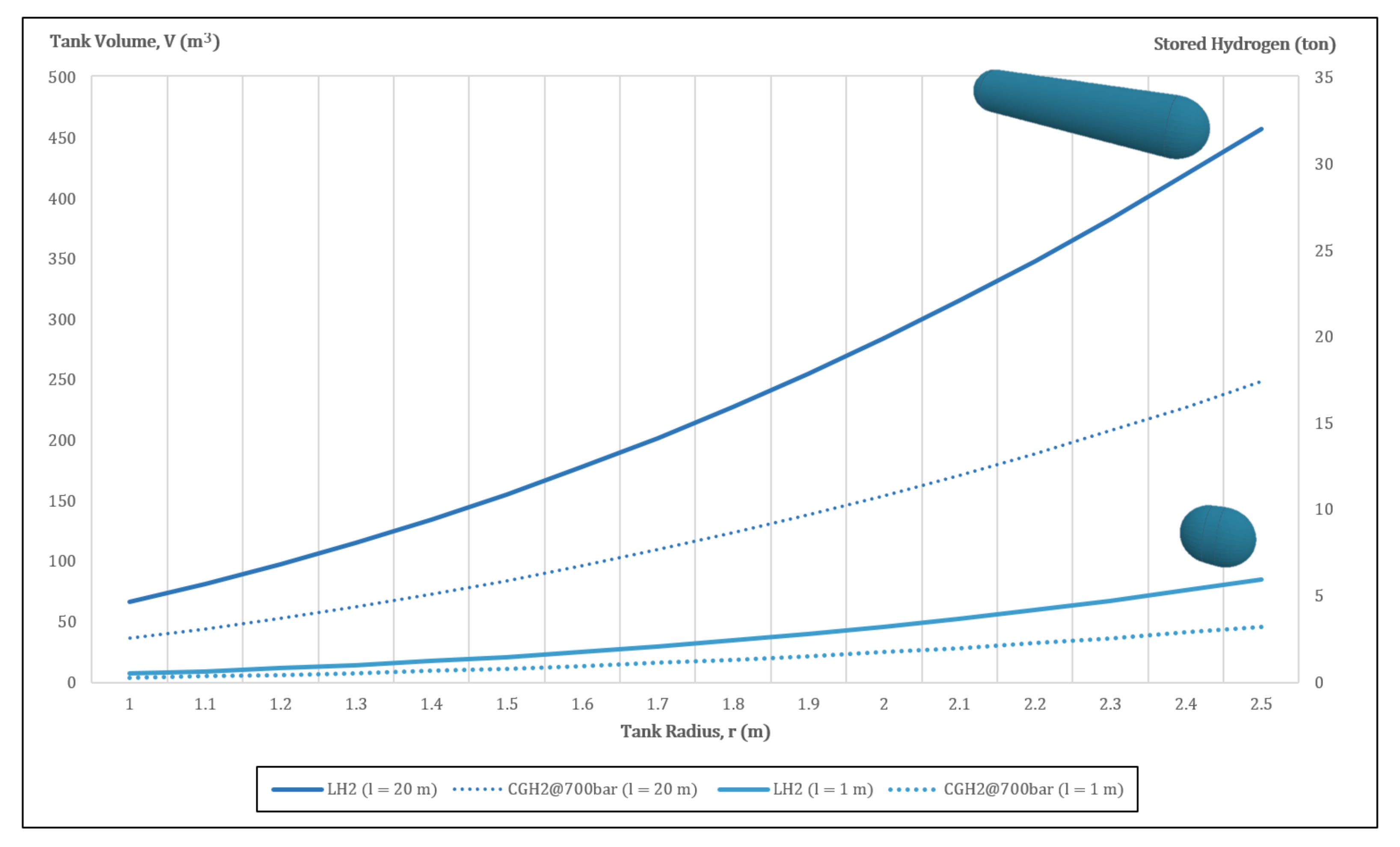
2.2. Liquid Hydrogen

Although liquid hydrogen (LH 2 ) storage has not been around as long as compressed hydrogen tanks have, it has existed for some time now; cryogenic tanks were first used about 50 years ago in the industrial and medical gas-transportation businesses, and they are fully adopted and commercially accessible today.
To obtain hydrogen in liquid form, it must first be cooled to below −253 °C, a process that usually requires both a lot of time and great amounts of energy—more precisely, as Moradi and Groth [7] elaborated, up to 40% of the energy content of the same hydrogen being cooled (as opposed to just 10% when it is compressed). Even so, cryogenic hydrogen storage under atmospheric conditions presents a larger energy density than when it is compressed (almost triple when at 35 MPa, as identified by A. Fradkov [10]) and therefore has better storage efficiency; this is why traditionally, liquid hydrogen has been preferred for space programs [11], aircraft flights [12], and intercontinental storage shipping [13], among others. However, due to its very low boiling temperature, hydrogen becomes problematic to store cryogenically for long periods of time, which puts it at risk of yield loss by natural evaporation; Barthelemy and his co-authors [8] asserted that this explains why it is not a favorable solution for on-board vehicle storage. However, it is the favored form for medium-/large-scale truck delivery and long-range international transport [14]; a cryogenic vessel can carry around 5000 kg of liquid hydrogen, five times the nominal capacity of current hydrogen gaseous pipe trailers [7], without the associated risks [15].
Current designs of liquid hydrogen tanks need to consider three primary parameters: shape, volume, and insulation.
The shape of the tank depends on a few elements, mainly the materials to be used, the space available for the tank, and the stresses it will be subjected to. As in the storage of many other liquids, Allideris and Janin [16] found that spherical or cylindrical shapes are also preferred for the storage of LH 2 , since there is better load distribution and avoidance of stress concentration at the corners of the typical quadrangular tanks. For any given volume, the sphere is known to be the geometrical object with the least surface area; thus, the passive heat flux with the exterior is reduced and the boil-off rate is lower, as pointed out by Mital et al. [17]. However, spherical tanks are hard to manufacture, have a large frontal surface, and are not particularly good at tessellating space (that is, they do not stack well). On the other hand, as G. Brewer cleverly explained, cylindrical tank shapes are much easier to fabricate, and while they may have the same frontal surface, they stack much better, thus yielding higher volumetric storage efficiencies and optimal storing configurations [18]. The major drawbacks of cylindrical-shaped vessels are the larger area-to-volume ratio (which result in a higher passive heat flux) and the uneven distribution of pressure close to the bases. To deal with this issue, Khandelwal and his co-authors [12] proposed to turn the ends of the cylinder into hemispherical caps; such spherocylinder is considered to be the standard shape for tanks nowadays as it puts together the best features of both geometries.
Regarding volume, this is usually set according to the required mass. Therefore, once the mass of liquid hydrogen needed has been defined, the volume of the tank is then determined by Equation (1). With V representing the volume of a capsule, it is computed by adding the volume of a sphere with radius r (accounting for both hemispheres) to the volume of the cylindrical part with length l.
V = 4 3 π r 3 + π r 2 l = π r 2 4 3 r + l
Hence, as we will see ahead, the tank’s shape parameters have to be chosen in accordance with the mass of the LH 2 required to be carried, its nominal temperature, the operating pressure of the vessel, and the insulation thickness [19]. At the time of its design, a trade-off has to be considered between the volume of the tank and the space available on the carrier.
Figure 3 shows the tank volume (on the left vertical axis) and the stored hydrogen mass (on the right vertical axis) as functions of the tank radius; the light-blue solid line refers to a spherocylinder with a length of just one meter, while the dark blue solid line represents a tank 20 m in length. The round-dotted lines indicate the performance of similar tanks with compressed gaseous hydrogen inside, at a pressure of 70 MPa. The increase in density with the transition from the gaseous to the liquid state is very clear here; a capsule tank 20 m in length can transport twice the mass of hydrogen if it is liquid instead of gaseous.
Understanding the differences in size between the interior vessel and the exterior tank is understanding insulation; the storage of hydrogen at such low temperatures requires special high-efficiency insulated tanks. This can be achieved by applying internal and/or external insulation. Internal insulation is always hard to implement since the materials are in direct contact with hydrogen in cryogenic temperatures; heat transfer phenomena cause the transition of hydrogen from a liquid state to a gas state at these contact boundaries, diffusing gaseous H 2 into the walls of the tank. This then increases the thermal conductivity of the insulation material, thus damaging its efficacy [12]. Therefore, the system would have to be impermeable to CGH 2 [18].
In the case of external insulation, the problem is not so much the direct contact with extremely low temperatures, but rather the contractions and expansions that the materials undergo, which come respectively from the charge and discharge of liquid hydrogen at these temperatures. Moreover, there is also an attachment issue for the support systems as well as possible mechanical damage from impact loads [18]. Nonetheless, these problems are more easily solved than those of internal insulation. Hence, the main challenge involving liquid hydrogen storage is the boil-off phenomenon; as previously explained, this occurs when heat is transferred to the tank’s interior, consequently warming the liquid hydrogen and effectively turning it into a gas (depending on several factors, up to 1 wt % per day due to heat in-leakages from the environment alone, as disclosed by Sherif et al. and confirmed by C. Yang and J. Ogden. [21,22]). Boil-off management is then an extremely relevant matter with regard to cryogenic hydrogen storage since it can lead to an unwanted pressure increase inside the rigid vessel; once the nominal maximum pressure is reached, the boil-off valve opens and ventilates part of the gas to the exterior. To reduce this effect—and thus reduce energy losses—several solutions have been adopted: Notardonato et al. [23] proposed an integration of cryo-coolers in the frame, while J. Wiley [24] recommended a storage combination with the chemical metal hydrides; Ho and Rahman favored a cooling combination with liquid nitrogen (which is used to `shield’ the insulated tank, hence drastically reducing the heat transfer to the environment) and the installation of passive insulation [25]. This last solution can branch into several techniques, as pointed out by A. Züttel and J. Reijerkerk [26,27], with the use of vacuum, foam, and multi-layer insulation:
  • Vacuum insulation. While a perfect vacuum may seem to be the best solution to eliminate the boil-off effect, it is also extremely difficult to achieve; as demonstrated by A. Colozza [28], peripheral equipment and venting devices are required to actively maintain the vacuum region. A vacuum chamber also raises issues about the thickness of the tank walls—they must be wide enough to withstand the buckling effect caused by external ambient pressure; however, as Millis et al. [29] reiterated, large walls in conjunction with additional stiffeners (required in-between the vacuum jacket shell) will inevitably increase the overall weight of the tank.
  • Foam insulation. Despite not having insulation levels as good as those of vacuum chambers, foam insulation is a passive technique, easier and cheaper to implement. Usually, these foams are very light, have low density, and low thermal conductivity; in his PhD thesis, I. Cumalioglu [30] studied how these are applied, sandwiched between two metal plaques, in order to improve structural stability and to better protect against external forces and impacts. Another great advantage of foam insulation over vacuum-jacketed insulation is its resistance to catastrophic failure; a pierced vacuum chamber would probably cause the overall collapse of the insulation layer, whereas foam insulation would not [26].
  • Multi-layer insulation. This method can be seen more as a compliment the previous two rather than as an alternative—although it is also possible to implement it as a stand-alone. Multi-layer insulation systems are commonly a set of reflective foil made of thermal radiation shields aligned perpendicularly to the direction of the heat flux; they are usually wrapped over the external layer of the tank in order to impede radiation heat transfer. These radiation shields mostly consist of alternate layers of thin aluminum foil and an insulating material such as fiberglass or polyester [8]. While additional layers may improve radiation heat insulation, it also increases heat transfer by conduction; to cite Khandelwal and his co-authors [12], the optimal recommended number of layers is then between 60 and 100. Naturally, more layers will also add to the overall weight of the tank. Another drawback of multi-layer insulation sheets is their sensitivity to pressure gradients during manufacturing, as studied by Allideris and Janin [16]; this leads to the need for a very specialized type of production, which is more expensive.
    Further attention needs to be given to damage use accumulation resultant from external loads such as impacts during operation or unpredictable accidents, which can lead to fiber breaks, delamination, and matrix cracking [8].
As was notably mentioned by Kamiya and his co-authors [31], while heat inputs may be minimized through the use of the above-mentioned insulation techniques, sloshing is not. Sloshing occurs mainly during the acceleration/deceleration periods of trailer transport, where heat may be generated by the inherent vibration of the tanks; this can be overcome with the introduction of slosh-baffles—a device that dampens the adverse effects of sloshing and also increases the natural frequency of the tank [21].
Having seen the various methods of preferred exterior insulation, what happens in the interior of such tanks remains to be analyzed. An important matter to consider here is the material compatibility between hydrogen and the substance with which the vessel is made; the inner part of these vessels is usually made of stretched stainless steel. However, it raises concerns about the possible effects of hydrogen embrittlement, where hydrogen atoms diffuse into the structure of the metal [32]; by accumulating at locations with higher cracking potential, severe changes to the metal’s mechanical properties may happen—mainly a decrease in ductility, toughness, and load-bearing capability. At the same time, it also increases hardness and thus the propensity for premature brittle fractures. Note that this effect can happen with hydrogen in both the gaseous and the liquid states, and that this issue can have even greater impact when considering multi-material assemblies (as is the case with both compressed and cryogenic vessels). Among the methods for minimizing hydrogen embrittlement, Li et al. [33] indicated the use of special inner-surface treatments involving coating and surface material modifications as one of the most conventional approaches.
Regarding safety issues, Petipas and Aceves [34] believed that any explosion scenario is very unlikely to happen, since hydrogen has a low adiabatic expansion energy at very low temperatures; however, potential leakages can effectively damage nearby valves and devices that have not been rated to withstand such low temperatures, thus causing further malfunctioning.

2.3. Cryo-Compressed Hydrogen

Cryo-compressed hydrogen (CCH 2 ) storage was introduced to overcome the disadvantages of both traditional storage methods mentioned above by combining their main characteristics, as explained by El-Eskandarany and Aceves et al. [35,36]. This storage occurs at cryogenic temperatures (not as low as with LH 2 ) on a pressurized vessel, although not as much as with CGH 2 ; it can comprise cold compressed hydrogen or hydrogen in a two-phase region (saturated liquid and vapor) [37]. Figure 4 illustrates hydrogen density as function of temperature and pressure, displaying the different storage methods discussed so far.
Usually, liquid hydrogen stored at ambient temperature is pumped through vacuum insulated piping to reach pressures of up to 85 MPa and densities as high as 80 g/L; an evaporator stage then converts it into a super-cooled gas before it is stored in special, carbon fiber-wrapped, metal, cryo-compressed vessels (similar to those of Type III for CGH 2 ) [38]. Moreno-Blanco and his co-authors [39] found that storage density can be higher this way since liquid hydrogen is slightly more compressible: at −252 °C, it is 87 g/L at 240 bar compared to 70 g/L at atmospheric pressure.
Cryo-compressed hydrogen storage presents some advantages when compared to traditional methods, such as an overall higher energy density, volumetric efficiency and gravimetric capacities [38], reduced boil-off effect [40], and thus reduced in-vessel over-pressurization and longer thermal endurance [41], among others. Stetson et al. also demonstrated how cryo-compressed storage tanks are one of the most versatile since they are designed to endure both very low temperatures and very high pressures [42]. However, there are still some limitations preventing this technology from becoming commercially viable; cryo systems are generally very complex and hard to implement, requiring the permanent and careful management and monitoring of their thermal insulation levels [38] as they have considerable maintenance costs, high energy needs for operation, and a short no-loss unused period [43].
Recently, numerous advancements have been made with respect to the geometry and the materials of the tanks used in these systems, since their performance highly depends on these aspects; thus far, an effort to compress the whole system was made, resulting in the halving of the vessel’s coating thickness to 1.5 cm. Nevertheless, Sdanghi et al. [38] emphasized that particular research should be carried out concerning the use of alloys of lighter density as coating materials.
Table 2 displays the main attributes of the three physical ways of storing hydrogen discussed so far.

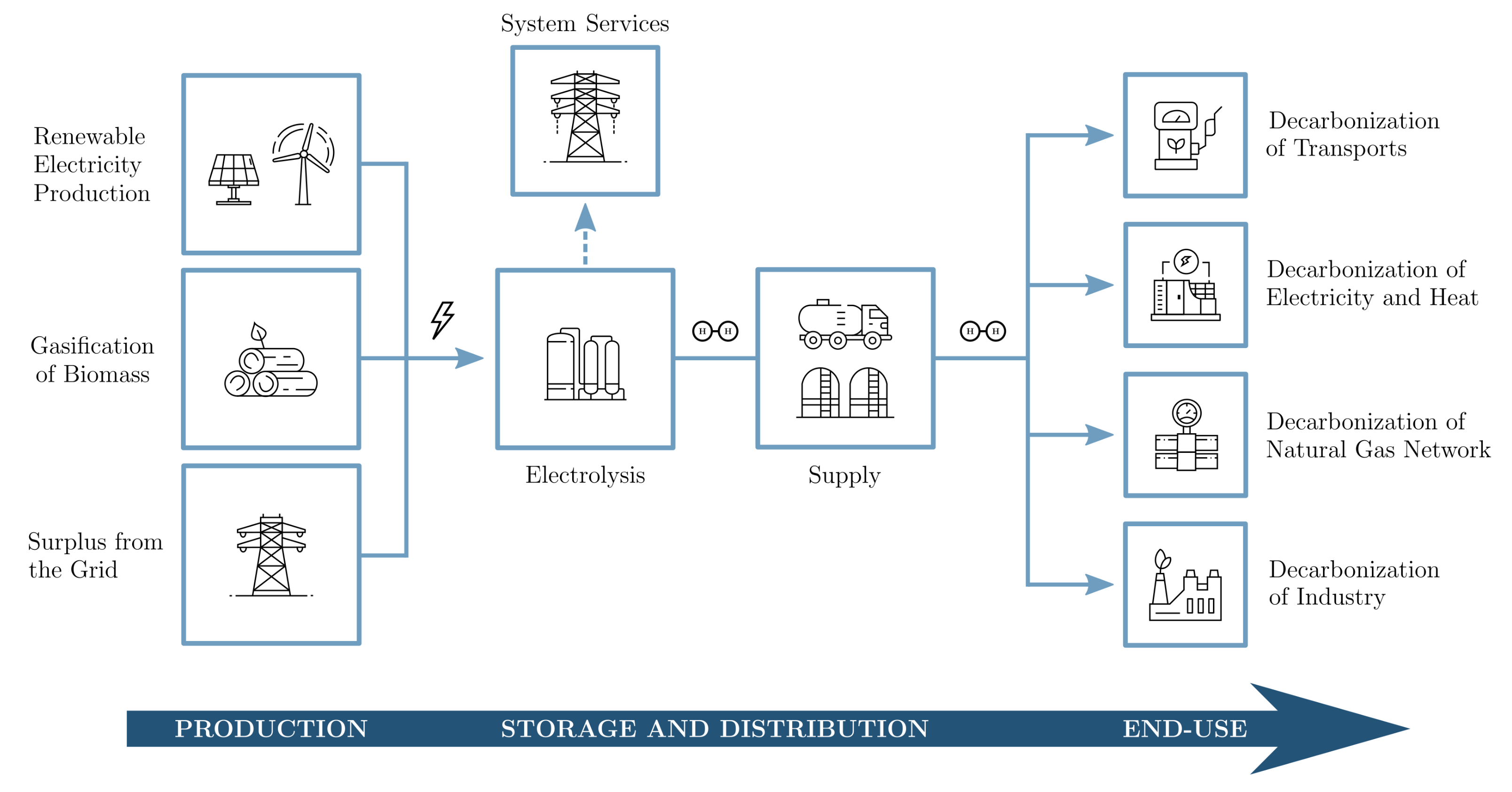
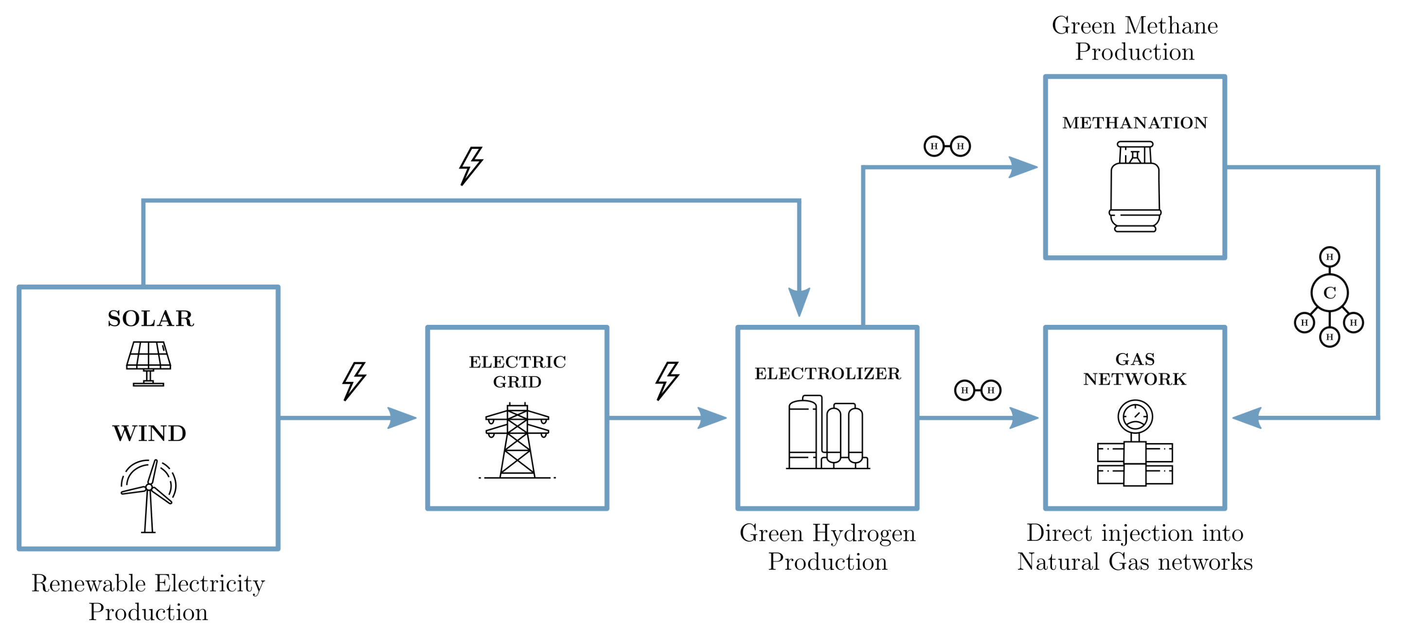
3. Hydrogen Integration in Power-to-Gas Networks

Once hydrogen has been produced and stored, it can be further transformed; one aforementioned option is H 2 synthesis to methane or synthetic natural gas (NG), a product then injected into the natural gas infrastructures (NGI) [44]. Figure 5 illustrates a typical Power-to-Gas (P2G) process; such systems connect the electric grid and the gas network, storing the excess renewable electricity in the form of H 2 /NG and providing it when needed.
Pure hydrogen can also be directly injected into the NGIs, although nowadays, still not in large percentages. As identified by Melaina et al. [45], this is especially due to its particular physical and chemical properties, which cause some concerns related to material durability, leakage, and safety. Moreover, the blending of hydrogen further diminishes the natural gas’ calorific value, hence reducing the amount of available energy in the network. This is why the conversion of electrolytic hydrogen into methane (through external sources of carbon oxides) is often a much more researched topic; since methane is a major component of natural gas, the P2G process derives from an NGI-compatible gas. However, as studied by Jaffe and Ogden [46], these processes are expensive and present lower efficiencies when methanation is included (around 56%) as opposed to when it is excluded (almost 70%). This fact has brought a lot of attention to this topic in the scientific community, making it crucial—I. Gondal [44] argues—that direct injection of hydrogen into natural gas networks is explored, targeting the characteristics of H 2 -NG mixtures; this can generally be fulfilled through the operators in the NGI’s Transmission and Distribution grids. These characteristics are specific to each NGI, depending on factors such as its geographic location, maximum hydrogen concentration allowed, the natural gas’ composition and flow rate, the structure of the network itself, and the end-use applications. Figure 6 shows the limits on hydrogen blending in natural gas networks for some locations around the world.
Hard Blend Limit refers to the current limit under normal circumstances, while the Soft Blend Limit is linked to the blend limit under certain conditions (see the note below). It is clear how different countries accredit different degrees of emphasis to this matter; while the maximum level of hydrogen content (by volume) currently allowed in the UK is only 0.1% [49], European regulations allow up to 12% [46], and US studies even propose levels between 5% and 15% given a prime condition structure [44].
Qadrdan et al. [49] joins a group of researchers that have previously investigated the effects of hydrogen injection into the NGIs and the consequent sensitivity of the gas supply chain [50,51,52,53,54,55], finding that major analysis starts off with the identification of four constituent parts of any P2G system: Gas Transmission, Gas Storage, Gas Distribution, and End-use Application. These four features will now be individually addressed, considering three thresholds of tolerable hydrogen concentration: Unaffected, Affected (when monitoring and technical adjustments are still needed), and Restricted (when it is still at the R&D stage).

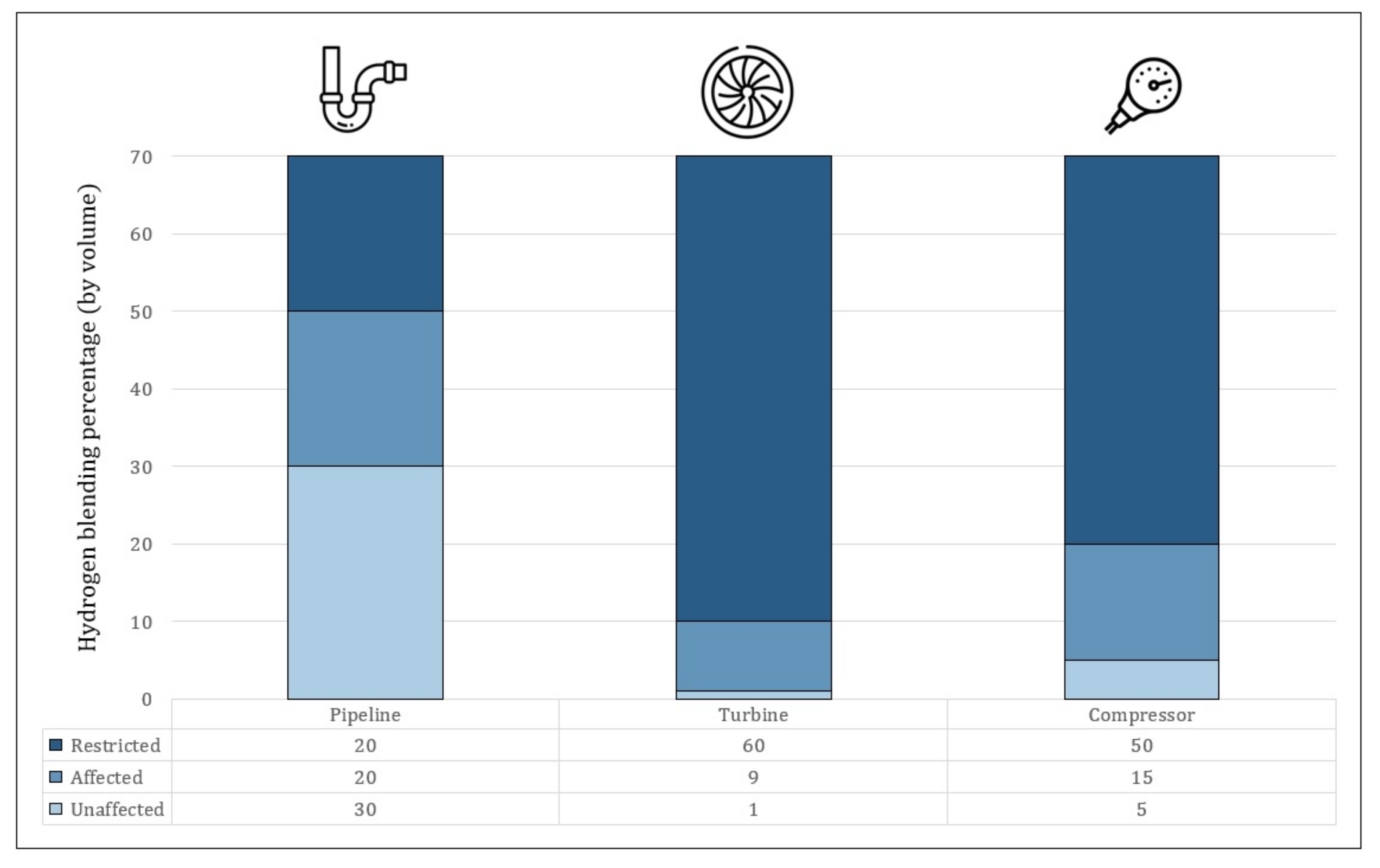
3.1. Evaluation of Gas Transmission Systems

The analysis of this P2G system is divided into three main components, these being the material of the pipeline, the gas turbines, and the compressors; Figure 7 presents the findings of the studies. It is in accordance with the research performed by Taamallah et al. [56], showing that while 30% hydrogen blending (by volume) does not affect the material aspect of the NGI pipeline at all, the gas turbines and compression systems should stay below 5%.
On the other hand, hydrogen concentrations of up to 10% and 20% are still permissible for the operation of turbines and compression stations, respectively, while pipelines can stand mixtures of up to 50% (given some technical adjustments); anything above those values is currently still being researched [57]. For instance, Mitsubishi Hitachi Power Systems, Ltd. has recently disclosed the successful test of a large-scale highly efficient turbine fed with a 30% hydrogen blend, attaining a stable combustion with a 10% reduction in carbon dioxide emissions [58].
An important factor that ought to be examined here is the effect of hydrogen blending in the natural gas supply chain. Considering an average lower calorific value of 10.2 kWh/m 3 for the natural gas circulating in the transport network, and 3 kWh/m 3 for hydrogen [20], this means that the injection of hydrogen into NGIs will translate into a reduction in the calorific power of the mixture circulating in the network. From a theoretical point of view, analyses have concluded that in a mixture with up to 22% of H 2 /NG blending, the calorific value remains within the limits currently imposed by regulation [48]; however, above this value—as I. Gondal pointed out in his book [59]—the energy density of the fuel is insufficient to satisfy consumer demands, thus requiring higher flow rates (that are currently limited by the existing compression stations).

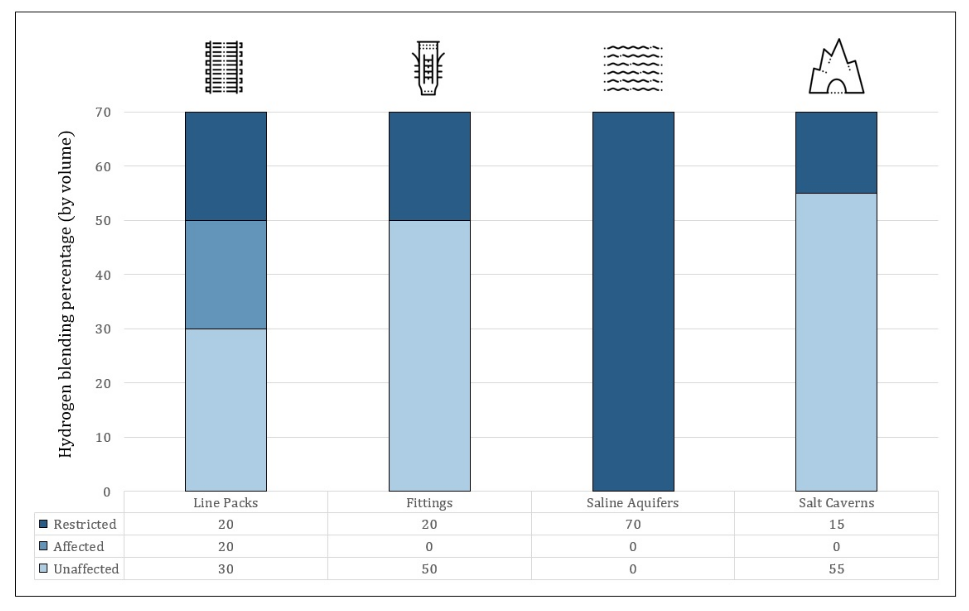
3.2. Evaluation of Gas Storage Methods

Gas storage is proposed in four different ways: inside pipelines (line packs), in fittings, inside saline aquifers, or in salt caverns. Figure 8 shows how hydrogen can be safely stored in percentages of up to 50% by volume—with the exception of in saline aquifers—without any technical problems, although monitoring is recommended in line packs from 30% upwards.
For hydrogen blending values above 50% and in aquifer storage, Patrick et al. [60] suggested that further research be performed; for instance, in saline aquifers, hydrogen storage is mainly restricted due to the presence of sulfidogenic bacteria, which are responsible for generating hydrogen sulfides; to the best knowledge of the author, no published literature has so far provided a blending proportion for H 2 /NG that is capable of being stored in saline aquifers.

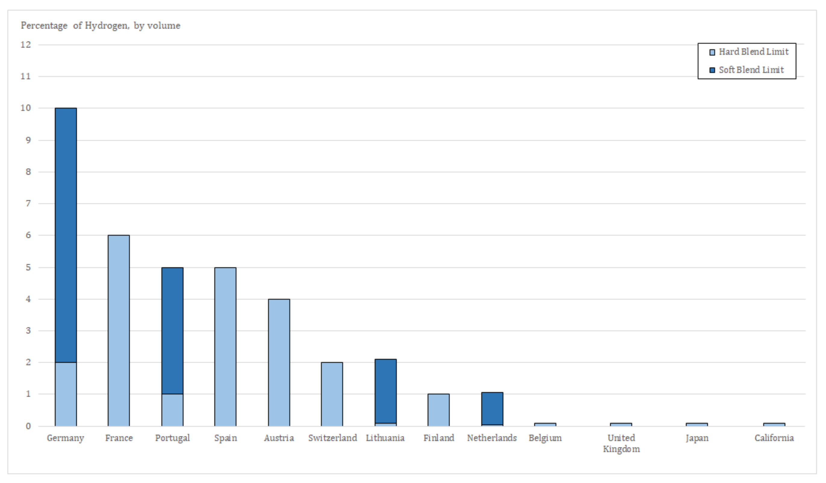
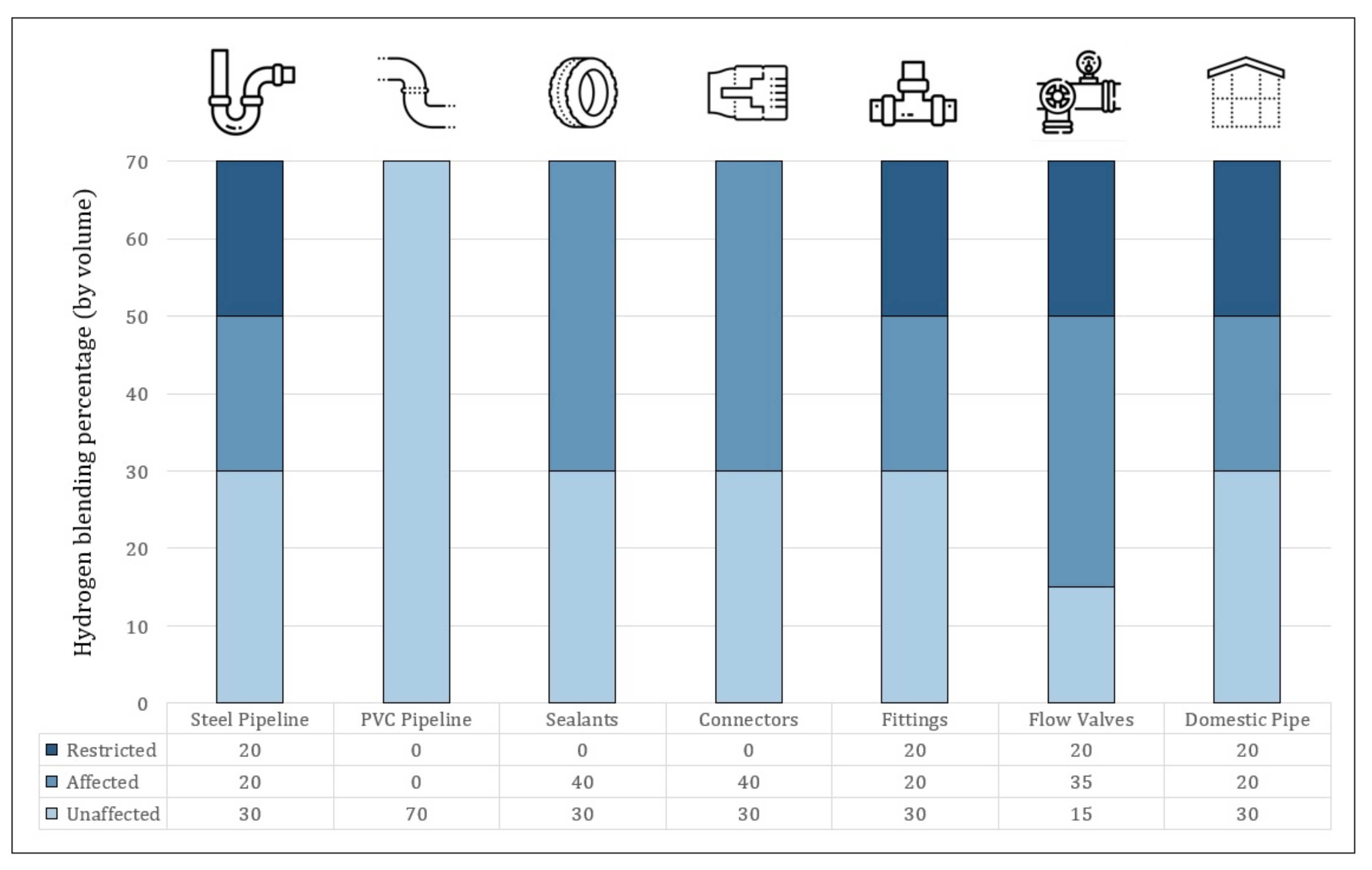
3.3. Evaluation of Gas Distribution Systems

Contrary to the two previous aspects of P2G systems, gas distribution systems are much less problematic when it comes to H 2 /NG mixtures, easily withstanding hydrogen injection values of around 50% (with monitoring), as shown in Figure 9.
Therefore, apart from possible leakages, J. Ogden and her co-authors [61] claimed that hydrogen blending in the domestic sector has no critical issues; special attention should thus be given to the use of leakage detectors and the definition of parameters related to Atmosphere Explosives zoning.
As mentioned before, since the calorific value of any typical H 2 /NG mix is lowered relative to pure methane (the major component of natural gas), then the admixture’s energy content reaching downstream of the distribution network, up to the end-user, may be considerably curtailed [62]. To compensate for this reduction and to keep a steady energy supply, flow rates will have to increase—possibly double, in the case of a hydrogen volume fraction of 20%. Even higher flow rates would imply structural modifications in the distribution systems, since those blending levels lead to increases in pressure losses over the pipeline, as noted by Ali Abd et al. [63]; this could ultimately lead to the replacement (and addition) of compressor stations and valve mechanisms [54].

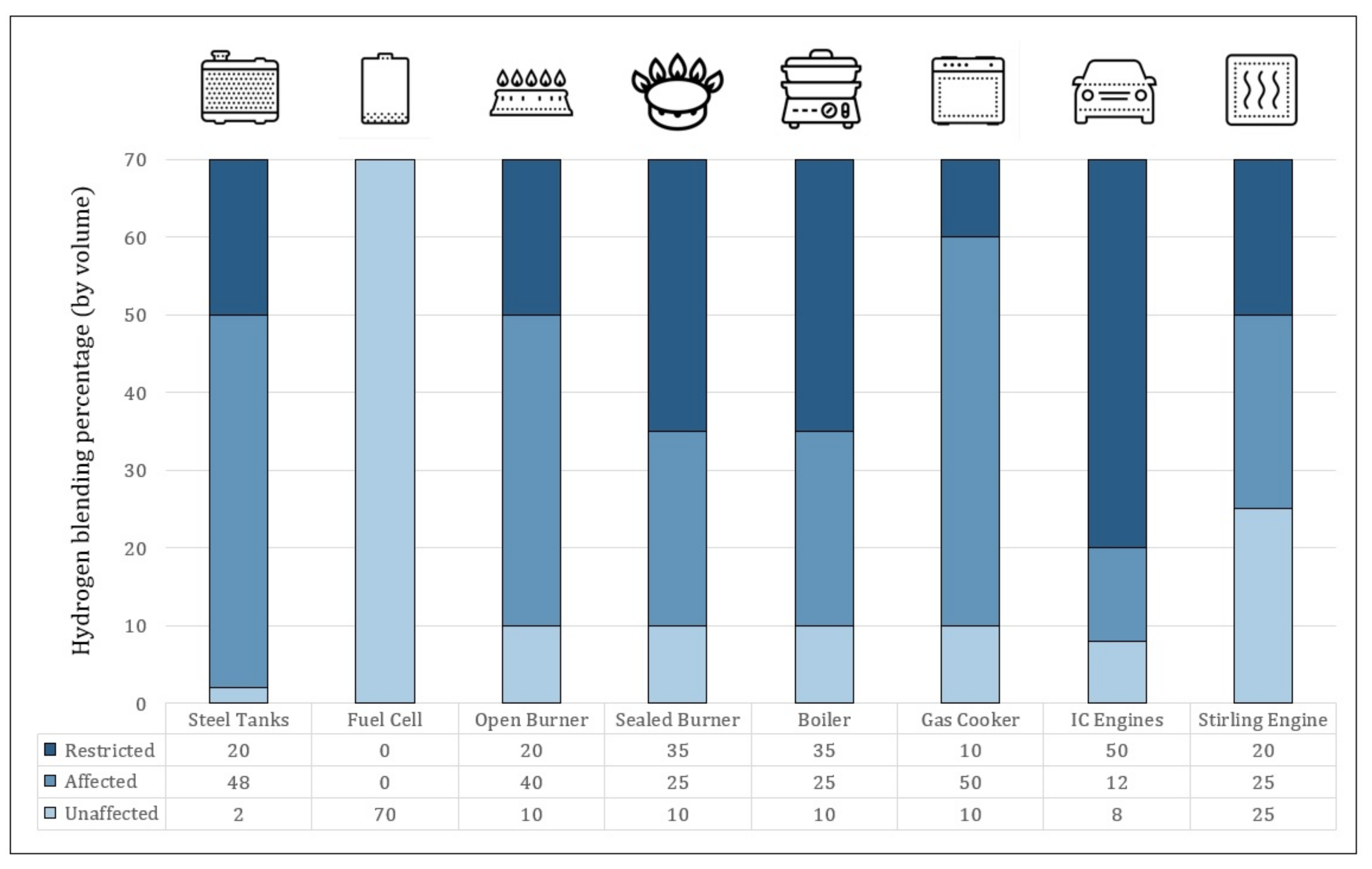
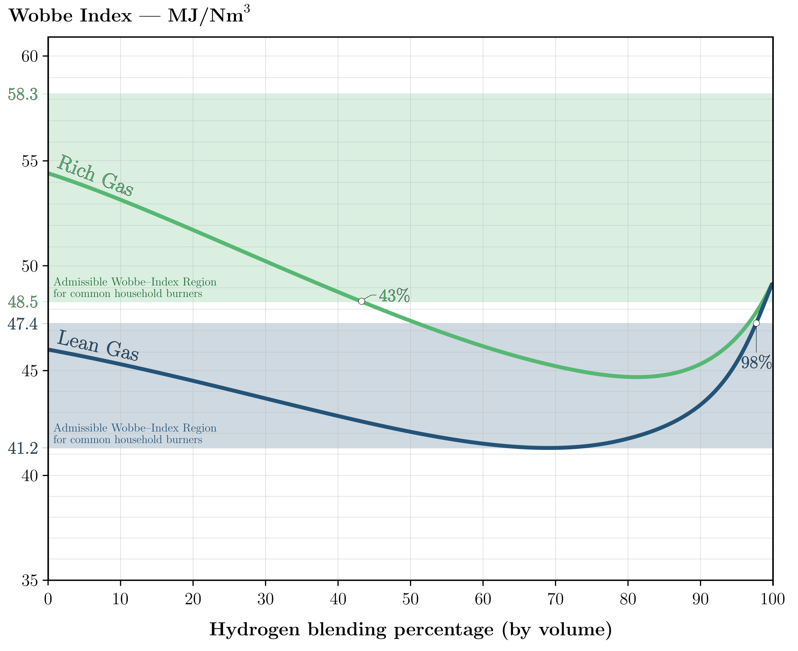
3.4. Evaluation of End-Use Applications

The injection of hydrogen into NGI causes significant and varied effects on end-use applications, both in relation to the appliances’ physical and chemical properties. Figure 10 shows the effect of hydrogen injection on end-use appliances.
For example, as discussed in Section 2.2, steel tanks used in vehicles operating on compressed natural gas (CNG) mixtures may suffer from hydrogen embrittlement—effectively leading to the weakening of the physical properties of the material, eventually causing crack propagation and ultimately, the failure of the equipment, as studied by Durbin and Malardier-Jugroot [64]; this is why the addition of hydrogen to CNG cars’ fuel is limited to just 2%, following current ISO standards [65]. The presence of hydrogen in natural gas under high pressures can also increase the permeability of steel, which is inadvisable; so, low-permeation materials are used to block hydrogen permeation. One such method proposed by Yabing et al. [66] is its application to stainless steel, namely through the use of low-carbon-content steel and the remaining carbon dispersion as carbides.
Turning now to the analysis of common burners in the domestic sector, the norm is to resort to the Wobbe Index ( I W ); this number is a measure of the energy content of a gas, based on its calorific value per unit volume, at standard pressure and temperature. It is expressed by Equation (2) and, as an indicator, is normally used to assess the interoperability of different equipment when a change in the fuel gas that feeds them occurs [44].
I W = H C V G S , w i t h G S = ρ S T P ρ a i r S T P
where H C V is the higher calorific value of the gas and G S its specific gravity—given by the quotient between the density of the gas and that of the air, both at standard temperature and pressure conditions (273.15 K, 101.33 kPa).
Regarding common burners, the admissible Wobbe number for lean and rich natural gas stands between 41.2–47.4 MJ/Nm 3 and 48.5–58.3 MJ/Nm 3 , respectively [44]. This has to do with the intrinsic differences of lean and rich NG; as previously suggested, natural gas is not a man-made product—therefore, its composition may vary in time and depend on the location of origin. Different composition means different energy content or different calorific value; consequently, Lois and his two co-authors [67] made a distinction for lean gas (HCV = 37.1 MJ/m 3 ) and rich gas (HCV = 41.1 MJ/m 3 ). Figure 11 shows the Wobbe Index variation in function of hydrogen blending percentages in H 2 /NG mixtures.
It is clear that for lean NG, a hydrogen volume fraction of up to 98% still falls within the expected Wobbe number, while for rich NG, it can only go up to 43%, thus being more susceptible to hydrogen injection. To solve concerns with respect to flame detection, Gondal I. A. [68] suggested the use of burner heads and sealings that have been rated to operate on a full range of H 2 /NG mixtures.
Another parameter influenced by hydrogen blending is the laminar/turbulent flame speed on devices such as boilers’ gas burners and gas turbines. Donohoe et al. [69] showed that, for instance, while a 20% H 2 injection in gas turbines can cause a laminar flame speed increase of just 5%, a turbulent flame speed would increase up to 20% [70].
Finally, regarding internal combustion engines running on natural gas (commonly used in power plants and some vehicles), the introduction of hydrogen into the NG mix has been observed to augment combustion temperatures and pressures, therefore increasing NOx emissions [50,71] and impacting on the performance of the engine. This issue needs to be addressed on a case-to-case basis, in accordance with the combustion attributes of each H 2 /NG blending.

4. Hydrogen Integration in Power-to-Power Smart Grids

Another option for stored hydrogen is its later use in feeding the electric grid. Purposefully producing electrical energy using hydrogen turbines or stationary fuel-cell stations may be seen as an inefficient option. However, a power-to-power (P2P) configuration for hydrogen’s value chain can be interesting to implement from the standpoint of service systems [3]. Within the current strategy for decarbonizing the electric sector, hydrogen’s participation in the electricity supply market may strengthen the security of supply [72], namely through the storage of large amounts that then feed high-power fuel cells during the years of low water availability [73,74]. Figure 12 shows a schematic for a P2P configuration.
Currently, most renewable energy sources are already integrated into smart grids through battery, thermal, and hydrogen energy storage. The majority of the research performed today is on expanding and diversifying this implementation [75]. Lin and his co-authors [76] warned that in the current trajectory of scarcity of resources, replacing fossil fuels used in the production of electricity—namely through the application of energy carriers such as hydrogen—is an issue of utmost relevance; the dissemination of these green-energies in smart-cities is becoming even more important now due to environmental concerns and the continued increase in fossil fuel prices [77]. Eltigani and Masri [78] noted, however, that the instability of the supply of these renewable sources can have severe impacts on electricity grids, causing voltage fluctuation and frequency change, which naturally lessens the service quality of the network. As a solution, Li [79] proposed the installation of reliable smart monitoring technologies together with sensor and communication systems; even more, a power system network for future smart grids is suggested, where distribution structures and high-end power generators are connected through bidirectional energy flows [80]. Naturally, the widespread implementation of energy storage systems, namely the ones mentioned in Section 2, can also curtail the intermittence problems of renewable energy sources, as studied by Guney and Tepe [81]. Hakimi and Moghaddas-Tafreshi [82] recommended an innovative domestic smart-system controller for heating and cooling, which can increase the size of generators and decrease the hydrogen tanks’ capacity through better power consumption management. Bornapour et al. [83], on the other hand, suggested a stochastic model to analyze microgrids so as to better coordinate the schedule between renewable and thermal units, thus optimizing the amount of hydrogen to be stored.

4.1. Hydrogen Application in Microgrids

Employing hydrogen as part of a distributed energy system can significantly improve smart grids, namely through the reduction of greenhouse gas emissions, a greater reliability, higher efficiency, and better supply security. Microgrids can simply be smart grids but in a smaller scale, sometimes consisting of only a solar panel hooked to an electrolyzer, a hydrogen storage tank, a fuel cell, and naturally, a load (a house). These microgrids can work in standalone mode or can be grid-tied in multi-microgrid networks, managed and operated through a two-way power flow and communication system. Zhang and his co-authors [84] performed a comprehensive evaluation of such a microgrid’s performance, proposing a weighted performance metric considering the electricity price, network emissions, and service quality—this way ensuring customer preference flexibility. They found that all modes of microgrids generally lower the electricity consumption when compared to conventional ones.
Li et al. [85] built a standalone microgrid to access hydrogen consumption in a network with optimized component sizing, keeping costs to a minimum. They used a unit commitment algorithm to determine the best strategy for operating the system, and a genetic algorithm was used to find the best size optimization while considering three main factors: operation strategy, the accuracy of generation/load forecasts, and the degradation of the system’s components. Zhang and Xiang [86], on the other hand, performed a thorough assessment of a grid-tied microgrid, where electricity and heat were generated to meet the local demand; the excess electricity was converted into hydrogen in order to be stored, which was then supplied to the fuel cell to produce power as necessary. A comparative analysis was performed on a system without the hydrogen storage component. The authors found that although both had a similar general performance index, the microgrid with energy storage and a fuel cell stack presented a higher environmental index and better service quality.

4.2. Hydrogen Economy in Smart Grids

The hydrogen economy is generally seen as an economic framework centered on the use of hydrogen as a medium for storing, transporting, and converting energy. Despite having been proposed several decades ago, it has become increasingly relevant today due to the sustained development of various hydrogen technologies, from electrolysers to fuel cells [87,88]. Hydrogen’s widespread implementation, through an effective collaboration between industry and academia, proves to be especially useful in smart grids as it allows renewable energy to be brought to virtually every sector of the economy [89]. There are many possibilities to efficiently convert current energy sources into hydrogen [90], with Alanne and Cao [91] even introducing the concept of the `zero-energy hydrogen economy’ (ZEH2E), an economic structure fundamentally centered on hydrogen, from individual residences to entire communities.
Demand side management (DSM) is another concept applicable to this type of economy, where the management of the electricity market is designed to optimize energy consumption, cut costs, and improve power supply reliability through a set group of actions. Techniques such as the ones illustrated in Figure 13 can help minimize the impacts of the typical intermittence of renewable energy sources, thus balancing the supply and demand sides in smart grids and overall providing better quality service. DSM in smart grids can effectively promote and mobilize users to change or transfer their power consumption according to dynamic prices [92].
Diamantoulakis et al. [93] used big data analysis to study the dynamic management of energy systems, predicting source and load sizes in smart grids and highlighting the efficiency of such tools in optimizing DSM. Wang and his co-authors [94], on the other hand, recommended a new DSM tool that encompasses a distributed energy storage program that can include CGH 2 or LH 2 ; from the results of their simulations, the outcome had high yields in peak reduction and also lower overall costs. Goulden et al. [95] presented two opposing visions of smart grids—one that is centralized, based on current institutional arrangements, and another that is decentralized, an alternative where distributed production and control are preferable. Using innovative concepts such as `energy consumer’ and `energy citizen’, the authors concluded that in order to properly design smart grids, it is necessary to look beyond technology; one must realize that a `smart user’ is essential to much of what is expected of demand side management. In Ireland, Finn and Fitzpatrick [96] studied the potential of implementing a price-based demand response on industrial consumers in order to increase their use of wind-generated electricity. The authors found that strategically increasing demand during times that are usually prone to curtailment and then shifting it in times of low prices is likely to increase consumer consumption of wind-generated electricity, thus possibly enabling a more sustainable production of green hydrogen.
Finally, with the progressive integration of hydrogen in the electricity market, Shi and his co-authors [97] turned to Denmark’s highly volatile electricity market prices to access the degree of adaptation of the hydrogen-based bidirectional energy storage. A sensitivity analysis was performed with regard to changes in hydrogen price and hydrogen storage capacity, confirming that this solution offers valuable proof in any energy market framework—namely ancillary operation services such as frequency control and power balancing. Moreover, frameworks established locally in the electricity/hydrogen trade showed improvement with the combination of renewables and lower peak demand [98].

5. Conclusions

Hydrogen technologies have been on the rise in the past few decades; their development has recently been pushed by several governments’ road maps for sustainability, supported by a widespread need to decarbonize the world. The global energy system is one of the highest sources of pollutants, thus urgently requiring fundamental changes to cope with sustainable objectives. Recent scientific research has led to better performances and higher efficiencies of hydrogen-related technologies, so much so that nowadays, their economic viability is hardly put aside. Truly understanding the strategic configurations of hydrogen’s value chain is required to thoroughly promote policies that expand the hydrogen economy; this immensely versatile energy vector is seen by some as indispensable to the full decarbonization of the energy sector.
The value chain of hydrogen starts at its green production, with the use of renewable resources. It is then transported to storage units so that it can later be distributed and used. The applications mentioned in this paper focus on two particular implementations of hydrogen: its injection and blending with natural gas in a Power-to-Gas configuration, and its conversion back to electricity in order to be integrated in the Power-to-Power configuration of a smart grid. Firstly, however, the storage methods available for these configurations should be studied so as to access their further usefulness.
Having a robust and reliable way of storing hydrogen is decisive in facing the potential demand for hydrogen on the energy market. This work performs a comprehensive review of the leading physical methods of storing hydrogen, starting with compressed gas—as the oldest and the only one operating at room temperature—since it is currently the most used and researched type of storage. The scientific community is devoted to improving the several types of tanks discussed, namely decreasing weight while maintaining their physical properties; another important advantage of CGH 2 is the fact that it has the lowest conversion losses from among the three (only about 10%, against the 40% of liquefaction). Liquid hydrogen storage has one clear advantage over its compressed counterpart—under almost atmospheric pressure, it presents close to triple the energy density of CGH 2 at 35 MPa. The problem is that it has to be stored at −253 °C. There exists a great body of research around the shape, volume, and insulation of tanks needed to withstand such temperatures, as well as their adaptation in order to be transported efficiently through intercontinental routes. Issues such as the boil-off effect, sloshing, and steel embrittlement, although tackled in clever ways, still hold back the vast utilization of this method. Cryo-compressed technology appears to solve both previous methods’ disadvantages; not only does it have a higher storage energy density than compressed hydrogen alone, but it also benefits from a reduction of the boil-off effect when compared to LH 2 . Another advantage is the versatility of cryo tanks, which can endure both very low temperatures and very high pressures; nonetheless, some drawbacks prevent CcH 2 systems from becoming commercially viable, namely their complexity, sensibility, high maintenance costs, and energy needs. Table 2 was put together to show all these points in a straightforward and clear way.
After examining the preeminent ways of physically storing hydrogen, this paper then contemplates two primary means of using it: integrating it in Power-to-Gas networks and utilizing it in Power-to-Power smart grids.
With regard to the first one, the fundamental target is to replace natural gas with hydrogen, from the transmission pipelines to the domestic burners. This cannot be accomplished instantly since the infrastructures, as they are now, were not designed and are not ready for a total substitution. As shown in the thorough analysis performed on this manuscript, a progressive blending must occur instead, assisted by a constant monitoring of the impacts that it may have on the various components of the NGI. Different countries and regions of the world have distinct norms and legislation on the maximum level of volumetric hydrogen content allowed, depending on their types of infrastructures and, naturally, political will. In general, most literature approaches this matter in a categorized manner, splitting the gas network into several parts and assessing the risk of hydrogen injection in each one of them. That is exactly what has been achieved in this paper, and the findings were clear: despite some components of the system being extremely tolerable to hydrogen presence, others are not. For instance, while PVC pipelines in the distribution network and fuel cells as an end-use can easily withstand up to 70% of hydrogen blending by volume, steel pipelines and storage line packs only accept up to 50% if monitored, and depending on technical adjustments. Some components, such as transmission system’s turbines and compressors, are even restricted to injections beyond percentages as low as 10% or 20%, respectively. For example, with respect to domestic burners, there is yet another issue; the Wobbe number must stay in-between a pre-determined range, as per legislated. Therefore, depending on the type of natural gas (lean or rich), there is so much blending that can be performed until the Wobbe Index is no longer admissible—98% for lean NG and only 43% for rich NG, as is plainly visible in Figure 11.
Regarding Power-to-Power integration, an extensive literature review is presented in this paper, addressing its various challenges. These novel systems are ever increasing their presence in the modern societies, where smart grids are interconnected throughout all services, supported by the fact that hydrogen’s participation in the electricity supply market strengthens the security of supply. Several solutions are proposed to meet different performance goals, namely the installation of reliable smart-monitoring, together with sensor and communication systems and an innovative domestic smart system controller for heating and cooling; everything is set to better coordinate energy demand schedules, so as to optimize the amount of hydrogen to be used and to achieve better overall power consumption management. A brief reflection is made on hydrogen’s applications in microgrids, both working as a stand-alone or within grid-tied multi-microgrid networks—managed and operated in a two-way power flow communication system. All mentioned studies conducted some kind of comparative analysis between those and conventional grids, finding the former to invariably perform better than the latter; even when they did have a similar performance index, H 2 microgrids often showed a better environmental index and service quality than their traditional counterpart.
Finally, when it comes to the hydrogen economy in general, many ideas came to the fore: from the natural, long-lasting collaboration between industry and academia—from which all the recent technological improvements bloomed, to the recent concept of Zero-Energy Hydrogen Economy—where the economic framework essentially supports hydrogen in its many forms. Several authors have advocated for the use of different types of DSM to help decrease the impacts of renewable energy’s intermittence, constantly balancing the supply and demand sides and promoting the existence of ’smart users’. While this in-depth study evaluates some of the possible uses of hydrogen integration in P2P networks, future work should include an analysis of the impacts of these systems on the operation of electric distribution networks—namely as ancillary services (voltage and frequency control, generation and load balancing, loss reduction, minimization of reverse power transit in transformers, and storage).
A final conclusion to be drawn from this article is that hydrogen is here to stay; it will not only help to accelerate the global energy transition, but it can well be essential for this transition to occur in time. Moreover, it represents an excellent opportunity to develop new green technologies that can be applied in all sectors of a hydrogen economy. Lastly, the path towards a society with deep hydrogen integration is truly promising, showing that both P2G and P2P configurations, supported by adequate storage methods, will be inseparable from a clean and efficient green future.

Author Contributions

Conceptualization, L.V. and R.C.; methodology, L.V. and R.C.; software, L.V.; validation, L.V. and R.C.; formal analysis, L.V., R.C. and A.P.; investigation, L.V.; resources, L.V.; data curation, L.V.; writing—original draft preparation, L.V.; writing—review and editing, R.C. and A.P.; visualization, L.V., R.C. and A.P.; supervision, R.C.; project administration, R.C.; funding acquisition, R.C. All authors have read and agreed to the published version of the manuscript.

Funding

This research was funded by Fundação para a Ciência e a Tecnologia (FCT), grant numbers UIDB/50021/2020 and UIDB/00066/2020.

Institutional Review Board Statement

Not applicable.

Informed Consent Statement

Not applicable.

Data Availability Statement

Not applicable.

Conflicts of Interest

The authors declare no conflict of interest. The funders had no role in the design of the study; in the collection, analyses, or interpretation of data; in the writing of the manuscript; or in the decision to publish the results.

Abbreviations

The following abbreviations are used in this manuscript:
CcH 2 Cryo-compressed Hydrogen
CGH 2 Compressed Gaseous Hydrogen
CNGCompressed Natural Gas
DSMDemand Side Management
H 2 Hydrogen
HCVHigher Calorific Value
LH 2 Liquid Hydrogen
NGNatural Gas
NGINatural Gas Infrastructure
P2GPower-to-Gas
P2PPower-to-Power
ZEH2EZero-Energy Hydrogen Economy

References

  1. Staffell, I.; Scamman, D.; Velazquez Abad, A.; Balcombe, P.; Dodds, P.E.; Ekins, P.; Shah, N.; Ward, K.R. The role of hydrogen and fuel cells in the global energy system. Energy Environ. Sci. 2019, 12, 463–491. [Google Scholar] [CrossRef] [Green Version]
  2. Commission, E. Hydrogen Strategy for a Climate-Neutral Europe. 2020. Available online: https://ec.europa.eu/energy/sites/ener/files/hydrogen_strategy.pdf (accessed on 16 February 2022).
  3. Vidas, L.; Castro, R. Recent Developments on Hydrogen Production Technologies: State-of-the-Art Review with a Focus on Green-Electrolysis. Appl. Sci. 2021, 11, 11363. [Google Scholar] [CrossRef]
  4. Shiva Kumar, S.; Himabindu, V. Hydrogen production by PEM water electrolysis—A review. Mater. Sci. Energy Technol. 2019, 2, 442–454. [Google Scholar] [CrossRef]
  5. Barbir, F. PEM electrolysis for production of hydrogen from renewable energy sources. Sol. Energy 2005, 78, 661–669. [Google Scholar] [CrossRef]
  6. Schmidt, O.; Gambhir, A.; Staffell, I.; Hawkes, A.; Nelson, J.; Few, S. Future cost and performance of water electrolysis: An expert elicitation study. Int. J. Hydrogen Energy 2017, 42, 30470–30492. [Google Scholar] [CrossRef]
  7. Moradi, R.; Groth, K.M. Hydrogen storage and delivery: Review of the state of the art technologies and risk and reliability analysis. Int. J. Hydrogen Energy 2019, 44, 12254–12269. [Google Scholar] [CrossRef]
  8. Barthelemy, H.; Weber, M.; Barbier, F. Hydrogen storage: Recent improvements and industrial perspectives. Int. J. Hydrogen Energy 2017, 42, 7254–7262. [Google Scholar] [CrossRef]
  9. Legault, M. The First Commercial Type V Composite Pressure Vessel. 2012. Available online: https://www.compositesworld.com/articles/next-generation-pressure-vessels (accessed on 13 January 2022).
  10. Fradkov, A.; Troitskii, V. Liquefier with two-stage conversion to obtain 98 per cent parahydrogen. Cryogenics 1965, 5, 136–137. [Google Scholar] [CrossRef]
  11. Granath, B. Liquid Hydrogen—The Fuel of Choice for Space Exploration. 2015. Available online: https://www.nasa.gov/content/liquid-hydrogen-the-fuel-of-choice-for-space-exploration (accessed on 8 December 2021).
  12. Khandelwal, B.; Karakurt, A.; Sekaran, P.R.; Sethi, V.; Singh, R. Hydrogen powered aircraft: The future of air transport. Prog. Aerosp. Sci. 2013, 60, 45–59. [Google Scholar] [CrossRef]
  13. Kawasaki. Kawasaki Hydrogen Road. Available online: https://global.kawasaki.com/en/hydrogen/ (accessed on 8 December 2021).
  14. Qiu, Y.; Yang, H.; Tong, L.; Wang, L. Research Progress of Cryogenic Materials for Storage and Transportation of Liquid Hydrogen. Metals 2021, 11, 1101. [Google Scholar] [CrossRef]
  15. Liu, Y.; Liu, Z.; Wei, J.; Lan, Y.; Yang, S.; Jin, T. Evaluation and prediction of the safe distance in liquid hydrogen spill accident. Process Saf. Environ. Prot. 2021, 146, 1–8. [Google Scholar] [CrossRef]
  16. Allideris, L.; Janin, F. Fuel System Components-Mechanical Tank Design Trade-Off, Technical Report, Task Technical Report 3.6.2.2, Cryoplane Project. 2002.
  17. Mital, S.K.; Gyekenyesi, J.Z.; Arnold, S.M.; Sullivan, R.M.; Manderscheid, J.M.; Murthy, P.L. Review of Current State of the Art and Key Design Issues with Potential Solutions for Liquid Hydrogen Cryogenic Storage Tank Structures for Aircraft Applications; Aerospace Engineering Papers; NASA: Washington, DC, USA, 2006. [Google Scholar]
  18. Brewer, G.D. Hydrogen Aircraft Technology; Routledge: London, UK, 2017. [Google Scholar]
  19. Haberbusch, M.S.; Stochl, R.J.; Culler, A.J. Thermally optimized zero boil-off densified cryogen storage system for space. Cryogenics 2004, 44, 485–491. [Google Scholar] [CrossRef]
  20. ToolBox, E. Fuels—Higher and Lower Calorific Values. Available online: https://www.engineeringtoolbox.com/fuels-higher-calorific-values-d_169.html (accessed on 6 January 2022).
  21. Sherif, S.; Zeytinoglu, N.; Veziroǧlu, T. Liquid hydrogen: Potential, problems, and a proposed research program. Int. J. Hydrogen Energy 1997, 22, 683–688. [Google Scholar] [CrossRef]
  22. Yang, C.; Ogden, J. Determining the lowest-cost hydrogen delivery mode. Int. J. Hydrogen Energy 2007, 32, 268–286. [Google Scholar] [CrossRef] [Green Version]
  23. Notardonato, W.U.; Swanger, A.M.; Fesmire, J.E.; Jumper, K.M.; Johnson, W.L.; Tomsik, T.M. Zero boil-off methods for large-scale liquid hydrogen tanks using integrated refrigeration and storage. IOP Conf. Ser. Mater. Sci. Eng. 2017, 278, 012012. [Google Scholar] [CrossRef]
  24. Wiley, J. Front Matter. In Hydrogen Storage Technologies; John Wiley & Sons, Ltd.: Hoboken, NJ, USA, 2012; pp. I–IX. [Google Scholar] [CrossRef]
  25. Ho, S.H.; Rahman, M.M. Nozzle injection displacement mixing in a zero boil-off hydrogen storage tank. Int. J. Hydrogen Energy 2008, 33, 878–888. [Google Scholar] [CrossRef]
  26. Züttel, A. Materials for hydrogen storage. Mater. Today 2003, 6, 24–33. [Google Scholar] [CrossRef]
  27. Reijerkerk, J. Potential of cryogenic hydrogen storage in vehicles. In Alternative fuels; Linde AG: Hoellriegelskreuth, Germany, 2004. [Google Scholar]
  28. Colozza, A.J.; Kohout, L. Hydrogen Storage for Aircraft Applications Overview; National Aeronautics and Space Administration, Glenn Research Center: Cleveland, OH, USA, 2002. [Google Scholar]
  29. Millis, M.G.; Tornabene, R.T.; Jurns, J.M.; Guynn, M.D.; Tomsik, T.M.; VanOverbeke, T.J. Hydrogen Fuel System Design Trades for High-Altitude Long-Endurance Remotely-Operated Aircraft. 2009. Available online: https://ntrs.nasa.gov/api/citations/20090013674/downloads/20090013674.pdf (accessed on 16 January 2022).
  30. Cumalioglu, I. Modeling and Simulation of a High Pressure Hydrogen Storage Tank with Dynamic Wall. Ph.D. Thesis, Texas Tech University, Lubbock, TX, USA, 2005. [Google Scholar]
  31. Kamiya, S.; Nishimura, M.; Harada, E. Study on Introduction of CO2 Free Energy to Japan with Liquid Hydrogen. Phys. Procedia 2015, 67, 11–19. [Google Scholar] [CrossRef] [Green Version]
  32. Elberry, A.M.; Thakur, J.; Santasalo-Aarnio, A.; Larmi, M. Large-scale compressed hydrogen storage as part of renewable electricity storage systems. Int. J. Hydrogen Energy 2021, 46, 15671–15690. [Google Scholar] [CrossRef]
  33. Li, X.; Ma, X.; Zhang, J.; Akiyama, E.; Wang, Y.; Song, X. Review of hydrogen embrittlement in metals: Hydrogen diffusion, hydrogen characterization, hydrogen embrittlement mechanism and prevention. Acta Metall. Sin. (Engl. Lett.) 2020, 33, 759–773. [Google Scholar] [CrossRef]
  34. Petitpas, G.; Aceves, S. Modeling of sudden hydrogen expansion from cryogenic pressure vessel failure. Int. J. Hydrogen Energy 2013, 38, 8190–8198. [Google Scholar] [CrossRef] [Green Version]
  35. El-Eskandarany, M.S. Solid-state hydrogen storage nanomaterials for fuel cell applications. In Mechanical Alloying, 3rd ed.; William Andrew Publishing: Norwich, NY, USA, 2020; pp. 229–261. [Google Scholar]
  36. Aceves, S.M.; Espinosa-Loza, F.; Ledesma-Orozco, E.; Ross, T.O.; Weisberg, A.H.; Brunner, T.C.; Kircher, O. High-density automotive hydrogen storage with cryogenic capable pressure vessels. Int. J. Hydrogen Energy 2010, 35, 1219–1226. [Google Scholar] [CrossRef]
  37. Ahluwalia, R.; Hua, T.; Peng, J.K.; Lasher, S.; McKenney, K.; Sinha, J.; Gardiner, M. Technical assessment of cryo-compressed hydrogen storage tank systems for automotive applications. Int. J. Hydrogen Energy 2010, 35, 4171–4184. [Google Scholar] [CrossRef]
  38. Sdanghi, G.; Maranzana, G.; Celzarda, A.; Fierro, V. Review of the current technologies and performances of hydrogen compression for stationary and automotive applications. Renew. Sustain. Energy Rev. 2019, 102, 150–170. [Google Scholar] [CrossRef]
  39. Moreno-Blanco, J.; Petitpas, G.; Espinosa-Loza, F.; Elizalde-Blancas, F.; Martinez-Frias, J.; Aceves, S.M. The storage performance of automotive cryo-compressed hydrogen vessels. Int. J. Hydrogen Energy 2019, 44, 16841–16851. [Google Scholar] [CrossRef]
  40. Andersson, J.; Grönkvist, S. Large-scale storage of hydrogen. Int. J. Hydrogen Energy 2019, 44, 11901–11919. [Google Scholar] [CrossRef]
  41. Bonadio, L. Fuels—Liquid hydrogen storage. In Encyclopedia of Electrochemical Power Sources; Elsevier: Amsterdam, The Netherlands, 2009; pp. 421–439. [Google Scholar]
  42. Stetson, N.; McWhorter, S.; Ahn, C. 1—Introduction to hydrogen storage. In Compendium of Hydrogen Energy; Gupta, R.B., Basile, A., Veziroğlu, T.N., Eds.; Woodhead Publishing Series in Energy; Woodhead Publishing: Sawston, UK, 2016; pp. 3–25. [Google Scholar] [CrossRef]
  43. Baetcke, L.; Kaltschmitt, M. Chapter 5—Hydrogen Storage for Mobile Application: Technologies and Their Assessment. In Hydrogen Supply Chains; Azzaro-Pantel, C., Ed.; Academic Press: Cambridge, MA, USA, 2018; pp. 167–206. [Google Scholar] [CrossRef]
  44. Gondal, I.A. Hydrogen integration in power-to-gas networks. Int. J. Hydrogen Energy 2019, 44, 1803–1815. [Google Scholar] [CrossRef]
  45. Melaina, M.W.; Antonia, O.; Penev, M. Blending Hydrogen into Natural Gas Pipeline Networks: A Review of Key Issues. 2013. Available online: https://www.energy.gov/sites/default/files/2014/03/f11/blending_h2_nat_gas_pipeline.pdf (accessed on 16 February 2022).
  46. Jaffe, A.M.; Ogden, J. Is Natural Gas the Transition Fuel for Hydrogen? 2014. Available online: https://www.cfr.org/blog/natural-gas-transition-fuel-hydrogen (accessed on 20 February 2022).
  47. Agency, I.E. Current Limits on Hydrogen Blending in Natural Gas Networks and Gas Demand per Capita in Selected Locations. Available online: https://www.iea.org/data-and-statistics/charts/current-limits-on-hydrogen-blending-in-natural-gas-networks-and-gas-demand-per-capita-in-selected-locations (accessed on 7 February 2022).
  48. EN-H2—Estratégia Nacional para o Hidrogénio. 2020. Available online: https://participa.pt/contents/consultationdocument/Estrate%CC%81gia%20Nacional%20para%20o%20Hidroge%CC%81nio%20DRAFT%20publicac%CC%A7ao.pdf (accessed on 20 November 2021).
  49. Qadrdan, M.; Abeysekera, M.; Chaudry, M.; Wu, J.; Jenkins, N. Role of power-to-gas in an integrated gas and electricity system in Great Britain. Int. J. Hydrogen Energy 2015, 40, 5763–5775. [Google Scholar] [CrossRef]
  50. Korb, B.; Kawauchi, S.; Wachtmeister, G. Influence of hydrogen addition on the operating range, emissions and efficiency in lean burn natural gas engines at high specific loads. Fuel 2016, 164, 410–418. [Google Scholar] [CrossRef]
  51. Mukherjee, U.; Elsholkami, M.; Walker, S.; Fowler, M.; Elkamel, A.; Hajimiragha, A. Optimal sizing of an electrolytic hydrogen production system using an existing natural gas infrastructure. Int. J. Hydrogen Energy 2015, 40, 9760–9772. [Google Scholar] [CrossRef]
  52. Lo Basso, G.; de Santoli, L.; Albo, A.; Nastasi, B. H2NG (hydrogen-natural gas mixtures) effects on energy performances of a condensing micro-CHP (combined heat and power) for residential applications: An expeditious assessment of water condensation and experimental analysis. Energy 2015, 84, 397–418. [Google Scholar] [CrossRef]
  53. labidine Messaoudani, Z.; Rigas, F.; Binti Hamid, M.D.; Che Hassan, C.R. Hazards, safety and knowledge gaps on hydrogen transmission via natural gas grid: A critical review. Int. J. Hydrogen Energy 2016, 41, 17511–17525. [Google Scholar] [CrossRef]
  54. de Vries, H.; Mokhov, A.V.; Levinsky, H.B. The impact of natural gas/hydrogen mixtures on the performance of end-use equipment: Interchangeability analysis for domestic appliances. Appl. Energy 2017, 208, 1007–1019. [Google Scholar] [CrossRef]
  55. Müller-Syring, G.; Henel, M.; Köppel, W.; Mlaker, H.; Sterner, M.; Höcher, T. Entwicklung von Modularen Konzepten zur Erzeugung, Speicherung und Einspeisung von Wasserstoff und Methan ins Erdgasnetz; DVGW Deutscher Verein des Gas-und Wasserfaches eV: Bonn, Germany, 2013. [Google Scholar]
  56. Taamallah, S.; Vogiatzaki, K.; Alzahrani, F.; Mokheimer, E.; Habib, M.; Ghoniem, A. Fuel flexibility, stability and emissions in premixed hydrogen-rich gas turbine combustion: Technology, fundamentals, and numerical simulations. Appl. Energy 2015, 154, 1020–1047. [Google Scholar] [CrossRef]
  57. Bolobov, V.I.; Latipov, I.U.; Popov, G.G.; Buslaev, G.V.; Martynenko, Y.V. Estimation of the Influence of Compressed Hydrogen on the Mechanical Properties of Pipeline Steels. Energies 2021, 14, 6085. [Google Scholar] [CrossRef]
  58. Power, M. MHPS Successfully Tests Large-Scale High-Efficiency Gas Turbine Fueled by 30% Hydrogen Mix. Available online: https://power.mhi.com/news/20180119.html (accessed on 6 January 2022).
  59. Gondal, I. 12—Hydrogen transportation by pipelines. In Compendium of Hydrogen Energy; Gupta, R.B., Basile, A., Veziroğlu, T.N., Eds.; Woodhead Publishing Series in Energy; Woodhead Publishing: Sawston, UK, 2016; pp. 301–322. [Google Scholar] [CrossRef]
  60. Preuster, P.; Alekseev, A.; Wasserscheid, P. Hydrogen Storage Technologies for Future Energy Systems. Annu. Rev. Chem. Biomol. Eng. 2017, 8, 445–471. [Google Scholar] [CrossRef]
  61. Ogden, J.; Jaffe, A.M.; Scheitrum, D.; McDonald, Z.; Miller, M. Natural gas as a bridge to hydrogen transportation fuel: Insights from the literature. Energy Policy 2018, 115, 317–329. [Google Scholar] [CrossRef]
  62. Chaczykowski, M.; Zarodkiewicz, P. Simulation of natural gas quality distribution for pipeline systems. Energy 2017, 134, 681–698. [Google Scholar] [CrossRef]
  63. Abd, A.A.; Naji, S.Z.; Thian, T.C.; Othman, M.R. Evaluation of hydrogen concentration effect on the natural gas properties and flow performance. Int. J. Hydrogen Energy 2021, 46, 974–983. [Google Scholar] [CrossRef]
  64. Durbin, D.; Malardier-Jugroot, C. Review of hydrogen storage techniques for on board vehicle applications. Int. J. Hydrogen Energy 2013, 38, 14595–14617. [Google Scholar] [CrossRef]
  65. Gas cylinders—High Pressure Cylinders for the On-Board Storage of Natural Gas as a Fuel for Automotive Vehicles. ISO 11439:2013; For Standardization, I.O. 2019. Available online: https://www.iso.org/standard/44755.html (accessed on 26 January 2022).
  66. He, Y.; Zhou, W.; Qian, G.; Chen, B. Methane storage in metal–organic frameworks. Chem. Soc. Rev. 2014, 43, 5657–5678. [Google Scholar] [CrossRef] [PubMed]
  67. Lois, E.; Keating, E.; Gupta, A. Fuels. In Encyclopedia of Physical Science and Technology, (Third Edition), 3rd ed.; Meyers, R.A., Ed.; Academic Press: New York, NY, USA, 2003; pp. 275–314. [Google Scholar] [CrossRef]
  68. Gondal, I.A. Infrastructure Analysis for Producing Hydrogen from Renewable Resources in Pakistan. Ph.D. Thesis, University of Engineering & Technology, Taxila, Pakistan, 2012. [Google Scholar]
  69. Donohoe, N.; Heufer, A.; Metcalfe, W.K.; Curran, H.J.; Davis, M.L.; Mathieu, O.; Plichta, D.; Morones, A.; Petersen, E.L.; Güthe, F. Ignition delay times, laminar flame speeds, and mechanism validation for natural gas/hydrogen blends at elevated pressures. Combust. Flame 2014, 161, 1432–1443. [Google Scholar] [CrossRef] [Green Version]
  70. Effects of Hydrogen Addition on the Flame Speeds of Natural Gas Blends Under Uniform Turbulent Conditions, Volume 4A: Combustion, Fuels and Emissions, Turbo Expo: Power for Land, Sea, and Air. Montreal, QC, Canada, 15-19 June 2015; 2015. Available online: https://asmedigitalcollection.asme.org/GT/proceedings-abstract/GT2015/56680/V04AT04A066/237014 (accessed on 25 January 2022). [CrossRef] [Green Version]
  71. Sofianopoulos, A.; Assanis, D.N.; Mamalis, S. Effects of Hydrogen Addition on Automotive Lean-Burn Natural Gas Engines: Critical Review. J. Energy Eng. 2016, 142, E4015010. [Google Scholar] [CrossRef]
  72. Alirahmi, S.M.; Assareh, E.; Chitsaz, A.; Ghazanfari Holagh, S.; Jalilinasrabady, S. Electrolyzer-fuel cell combination for grid peak load management in a geothermal power plant: Power to hydrogen and hydrogen to power conversion. Int. J. Hydrogen Energy 2021, 46, 25650–25665. [Google Scholar] [CrossRef]
  73. Okundamiya, M. Size optimization of a hybrid photovoltaic/fuel cell grid connected power system including hydrogen storage. Int. J. Hydrogen Energy 2021, 46, 30539–30546. [Google Scholar] [CrossRef]
  74. Song, P.; Sui, Y.; Shan, T.; Hou, J.; Wang, X. Assessment of hydrogen supply solutions for hydrogen fueling station: A Shanghai case study. Int. J. Hydrogen Energy 2020, 45, 32884–32898. [Google Scholar] [CrossRef]
  75. Parra, D.; Valverde, L.; Pino, F.J.; Patel, M.K. A review on the role, cost and value of hydrogen energy systems for deep decarbonisation. Renew. Sustain. Energy Rev. 2019, 101, 279–294. [Google Scholar] [CrossRef]
  76. Lin, R.H.; Zhao, Y.Y.; Wu, B.D. Toward a hydrogen society: Hydrogen and smart grid integration. Int. J. Hydrogen Energy 2020, 45, 20164–20175. [Google Scholar] [CrossRef]
  77. Nicoletti, G.; Arcuri, N.; Nicoletti, G.; Bruno, R. A technical and environmental comparison between hydrogen and some fossil fuels. Energy Convers. Manag. 2015, 89, 205–213. [Google Scholar] [CrossRef]
  78. Eltigani, D.; Masri, S. Challenges of integrating renewable energy sources to smart grids: A review. Renew. Sustain. Energy Rev. 2015, 52, 770–780. [Google Scholar] [CrossRef]
  79. Li, Z. Notice of Retraction: Comparison and Analysis of Dispatching Protocols in China. In Proceedings of the 2010 Asia-Pacific Power and Energy Engineering Conference, Chengdu, China, 28–31 March 2010; pp. 1–4. [Google Scholar] [CrossRef]
  80. Kolhe, M. Smart Grid: Charting a New Energy Future: Research, Development and Demonstration. Electr. J. 2012, 25, 88–93. [Google Scholar] [CrossRef]
  81. Guney, M.S.; Tepe, Y. Classification and assessment of energy storage systems. Renew. Sustain. Energy Rev. 2017, 75, 1187–1197. [Google Scholar] [CrossRef]
  82. Hakimi, S.M.; Moghaddas-Tafreshi, S.M. Optimal Planning of a Smart Microgrid Including Demand Response and Intermittent Renewable Energy Resources. IEEE Trans. Smart Grid 2014, 5, 2889–2900. [Google Scholar] [CrossRef]
  83. Bornapour, M.; Hooshmand, R.A.; Parastegari, M. An efficient scenario-based stochastic programming method for optimal scheduling of CHP-PEMFC, WT, PV and hydrogen storage units in micro grids. Renew. Energy 2019, 130, 1049–1066. [Google Scholar] [CrossRef]
  84. Zhang, L.; Gari, N.; Hmurcik, L.V. Energy management in a microgrid with distributed energy resources. Energy Convers. Manag. 2014, 78, 297–305. [Google Scholar] [CrossRef]
  85. Li, B.; Roche, R.; Paire, D.; Miraoui, A. Sizing of a stand-alone microgrid considering electric power, cooling/heating, hydrogen loads and hydrogen storage degradation. Appl. Energy 2017, 205, 1244–1259. [Google Scholar] [CrossRef] [Green Version]
  86. Zhang, L.; Xiang, J. The performance of a grid-tied microgrid with hydrogen storage and a hydrogen fuel cell stack. Energy Convers. Manag. 2014, 87, 421–427. [Google Scholar] [CrossRef]
  87. Pelaez-Samaniego, M.R.; Riveros-Godoy, G.; Torres-Contreras, S.; Garcia-Perez, T.; Albornoz-Vintimilla, E. Production and use of electrolytic hydrogen in Ecuador towards a low carbon economy. Energy 2014, 64, 626–631. [Google Scholar] [CrossRef]
  88. Hajimiragha, A.; Fowler, M.W.; Cañizares, C.A. Hydrogen economy transition in Ontario—Canada considering the electricity grid constraints. Int. J. Hydrogen Energy 2009, 34, 5275–5293. [Google Scholar] [CrossRef]
  89. Brandon, N.; Kurban, Z. Clean energy and the hydrogen economy. Philos. Trans. R. Soc. A Math. Phys. Eng. Sci. 2017, 375, 20160400. [Google Scholar] [CrossRef]
  90. Marbán, G.; Valdés-Solís, T. Towards the hydrogen economy? Int. J. Hydrogen Energy 2007, 32, 1625–1637. [Google Scholar] [CrossRef] [Green Version]
  91. Alanne, K.; Cao, S. Zero-energy hydrogen economy (ZEH2E) for buildings and communities including personal mobility. Renew. Sustain. Energy Rev. 2017, 71, 697–711. [Google Scholar] [CrossRef]
  92. Islam, N.; Xu, Z.; Gao, Y.; Hussain, M.; Cheng, P. Demand Side Management for Smart Grid Based on Smart Home Appliances with Renewable Energy Sources and an Energy Storage System. Math. Probl. Eng. 2020, 2020, 9545439. [Google Scholar] [CrossRef]
  93. Diamantoulakis, P.D.; Kapinas, V.M.; Karagiannidis, G.K. Big Data Analytics for Dynamic Energy Management in Smart Grids. Big Data Res. 2015, 2, 94–101. [Google Scholar] [CrossRef] [Green Version]
  94. Wang, K.; Li, H.; Maharjan, S.; Zhang, Y.; Guo, S. Green Energy Scheduling for Demand Side Management in the Smart Grid. IEEE Trans. Green Commun. Netw. 2018, 2, 596–611. [Google Scholar] [CrossRef]
  95. Goulden, M.; Bedwell, B.; Rennick-Egglestone, S.; Rodden, T.; Spence, A. Smart grids, smart users? The role of the user in demand side management. Energy Res. Soc. Sci. 2014, 2, 21–29. [Google Scholar] [CrossRef]
  96. Finn, P.; Fitzpatrick, C. Demand side management of industrial electricity consumption: Promoting the use of renewable energy through real-time pricing. Appl. Energy 2014, 113, 11–21. [Google Scholar] [CrossRef]
  97. You, S.; Hu, J.; Zong, Y.; Lin, J. Value assessment of hydrogen-based electrical energy storage in view of electricity spot market. J. Mod. Power Syst. Clean Energy 2016, 4, 626–635. [Google Scholar] [CrossRef] [Green Version]
  98. Xiao, Y.; Wang, X.; Pinson, P.; Wang, X. A Local Energy Market for Electricity and Hydrogen. IEEE Trans. Power Syst. 2018, 33, 3898–3908. [Google Scholar] [CrossRef] [Green Version]
Figure 1. General flowchart of hydrogen’s value chain. Adapted from [3].
Energies 15 03160 g001
Figure 2. Different types of pressure vessels. Adapted from [8].
Energies 15 03160 g002
Figure 3. Relation between radius, volume, and stored mass of a typical hydrogen capsule-shaped tank. Values obtained from Equation (1); hydrogen density from [20]. Note: Dimensions shown here are of the interior vessel. Nowadays’ cryogenic trailers may have these dimensions for the exterior tank, thus having much smaller interior capsules than the ones shown in this graph. For example, when Kawasaki announced its Hydrogen Road vision for the future [13], concept designs of liquefied hydrogen containers for land transportation carried about 5000 kg of liquid hydrogen.
Energies 15 03160 g003
Figure 4. Correlation of hydrogen density and temperature for different conditions.
Energies 15 03160 g004
Figure 5. Flowchart of a power-to-gas hydrogen value chain configuration. Adapted from [3].
Energies 15 03160 g005
Figure 6. Current limits on hydrogen blending in natural gas networks for selected locations. Adapted from [47]. Note: The soft blending limits shown reflect the following conditional parameters: (1) Germany, if there are no compressed natural gas filling stations connected to the network; (2) Portugal, differential obtained through other renewable gases such as biogas and biomethane [48]; (3) Lithuania, when pipeline pressure is greater than 16 bar; (4) Netherlands, for high-calorific gas [47].
Energies 15 03160 g006
Figure 7. Susceptibility of P2G transmission elements to different volume fractions of hydrogen blending.
Energies 15 03160 g007
Figure 8. Susceptibility of P2G storage options to different volume fractions of hydrogen blending.
Energies 15 03160 g008
Figure 9. Susceptibility of P2G distribution elements to different volumes of hydrogen blending.
Energies 15 03160 g009
Figure 10. Susceptibility of P2G end-use applications to different volumes of hydrogen blending.
Energies 15 03160 g010
Figure 11. Behavior of the Wobbe Index for different hydrogen contents in natural gas mixtures.
Energies 15 03160 g011
Figure 12. Flowchart of a power-to-power hydrogen value chain configuration. Adapted from [3].
Energies 15 03160 g012
Figure 13. Demand Side Management techniques, both Responsive and Efficient Demand types.
Energies 15 03160 g013
Table 1. Major features of compressed hydrogen storage vessels.
Vessel Type Type IType IIType IIIType IV
Material Composition
Core structureMetalMetalCompositeComposite
Top linerMetalMetalMetalPolymer
Exterior wrappingn.a.CompositeCompositeComposite
Physical Properties
Service pressure (MPa)50n.a.45100
Weight ratio (kg/L-H 2 )1.500.900.400.25
Miscellaneous
Weight performance0+++
Cost performance+++0
Main applicationIndustryStationaryPortablePortable
Note: plus and minus signs are intended to give a qualitative assessment of the respective features, when compared to baseline ‘0’.
Table 2. Major features of physical hydrogen storage technologies.
Storage Method CGH 2 LH 2 CCH 2
Operational Parameters
Service pressureVery HighAmbientVery High
Service temperatureAmbientVery LowVery Low
Hydrogen densityModerateHighVery High
System Characteristics
Compression processRequiredNot RequiredRequired
Liquefaction processNot RequiredRequiredNot Required
Thermal insulationNot RequiredRequiredRequired
Tank costModerateHighModerate
Technology Features
Boil-off effectModerateVery HighHigh
Hydrogen permeationHighModerateHigh
Cooling capacityn.a.Very HighVery High
CGH2: Compressed Gaseous Hydrogen; LH2: Liquid Hydrogen; CCH2: Cryo-compressed Hydrogen.
Publisher’s Note: MDPI stays neutral with regard to jurisdictional claims in published maps and institutional affiliations.

