Article

The Performance Analysis of an Integrated CO2 Refrigeration System with Multi-Ejectors Installed in a Supermarket

by
Engin Söylemez
1,*,
Armin Hafner
1,
Christian Schlemminger
2,
Ekaterini E. Kriezi
3 and
Vahid Khorshidi
3
1
Process and Power Research Group Trondheim, Department of Energy and Process Engineering, Norwegian University of Science and Technology (NTNU), 7491 Trondheim, Norway
2
Sintef Energy Research, Department of Thermal Energy, 7465 Trondheim, Norway
3
RAC R&D Danfoss A/S -Nordborgvej 81, 6430 Nordborg, Denmark
*
Author to whom correspondence should be addressed.
Energies 2022, 15(9), 3142; https://doi.org/10.3390/en15093142
Submission received: 16 March 2022 / Revised: 20 April 2022 / Accepted: 21 April 2022 / Published: 25 April 2022

Abstract

:
The field data from an integrated CO2 refrigeration system installed in a supermarket located north of the capital of Lisbon was analyzed. The goal was to demonstrate the effect and performance of multi-ejectors on a refrigeration system operating in a warm climate. The measurement results for the system with and without activating ejectors were compared. It was observed that the system with a multi-ejector operation had considerable performance superiority. The ejectors improved the cooling capacity of the medium temperature stage of the system by 17.4%. The system with active ejectors had 7.5% less total power consumption compared to the ejector off mode of the same system.

1. Introduction

There are variations in the enhancements expedient to improve the energy efficiency of transcritical CO2 (carbon dioxide) refrigeration systems in food retail stores, particularly for those located in warm and tropical regions. A rising number of such installations are being built [1,2], and scientific investigations support the knowledge transfer [3,4]. According to a report published by Shecco [2], exponential growth has been observed in the number of transcritical CO2 refrigeration installations between 2008 and 2018, and today, the total number of these installations is around 35,500 across the world. The majority of these systems are commercial supermarket applications, i.e., 29,000 installations [2].
The basic transcritical CO2 system, booster refrigeration system, BRS, (1st generation), is a reliable “CO2 only” solution for the large-scale refrigeration systems applied in moderate climates [5]. After scientific efforts, the 1st generation system has been advanced by adding parallel compression (2nd generation) and then further improved by implementing a multi-ejector (ME) (3rd generation).
There has been a scientific effort to enhance the energy performance of CO2 BRS to the present time. Several studies have been performed to investigate the effect of different solutions, such as flooded (overfed) evaporators (FE), parallel compression, and mechanical subcooling on the improved CO2 refrigeration systems, by comparing them with CO2 BRS and conventional systems based on synthetic refrigerants [6,7,8]. The studies have also focused on fully integrated (all-in-one) CO2 systems. To meet the multiple demands in terms of heating, cooling, and air-conditioning (AC) simultaneously in supermarkets, those systems that have promising energy performances and environmental benefits are becoming popular [3]. Depending on the needs and applications, the CO2 refrigeration system can be designed to meet only space heating (SH), only domestic hot water (DHW), air conditioning, or all of them, along with the baseline demand for refrigeration for chilled and frozen products [9,10,11,12,13].
Since 2014, the installation of transcritical CO2 refrigeration systems for retail food applications has gained momentum (2885 units in Europe in 2013 to more than 29,000 units in 2020 [14]). One of the paramount reasons for this development was the introduction of the advanced ME system [15], which enables and supports the integration of energy-efficient solutions, such as thermal storage, expansion work recovery due to two-phase ejectors, and FE, and extends the operation of the parallel compressors [3]. Karampour and Sawalha (2017) [16] investigated a CO2 BRS integrated with SH, DHW, and AC systems utilized in a supermarket in Sweden. With reference to field measurement data, the operating parameters were defined; then, the integrated energy system concept was modeled and compared to stand-alone energy systems in three different climate zones. They found that a fully integrated CO2 BRS is suitable for cold climates. They also recommended the implementation of FE, ME, mechanical subcooling, and gas cooler (GC) evaporative cooling for units operating in hot climates [16]. Gullo et al. (2017) [17] theoretically examined state-of-the-art pure CO2 refrigeration plants installed in food retail stores in different European climates. The results of their examination showed that the ME concept eliminates the energy efficiency limit of transcritical CO2 refrigeration systems in high ambient temperature climates. Additionally, energy savings of between 17.9–33.6% and 19.9–24.6% in mild and warm climates, respectively, can be achieved using MEs [17]. Singh et al. (2020) [18] evaluated a CO2 refrigeration system with a novel ME design (the ejectors in series configuration) with a cooling capacity of 33 kW installed in a test facility, simulating the demands of a supermarket in India. They analyzed the effect of an internal heat exchanger (IHX) and FE on the proposed system and compared its performance with the five supermarket applications in Sweden. The results revealed that (1) with IHX, a 7.2% increase in COP was achieved in comparison with the system without IHX (2) with FE, and a decrease of 6.2% was achieved in power input ratio (3). Although the proposed system (with ME and Fe) was located in a region with higher outdoor temperatures, it has equal COP levels with the three of the systems established in Sweden [18]. In one of the theoretical studies by Gullo et al. (2017b) [19], the energy consumption of a CO2 refrigerant system with ME was compared with a R404A-based system and several CO2 BRS configurations employed in Southern Europe. The results indicated that the CO2 system equipped with ME, PC, and FE (for both low-temperature, LT, and medium-temperature, MT, stages) for warm climate regions decreases the annual energy consumption by 25% compared to the R404A-based system. Pardiñas et al. (2018) [20] introduced innovative features to integrated transcritical CO2 systems. They numerically modeled an integrated system that included both parallel compression and MEs for responding to refrigeration and AC demands. The numerical findings revealed that (1) adding parallel compression to the BRS leads to a 19% decrease in power consumption at an ambient temperature of 30 °C (2) employing MEs leads to up to an 8% additional reduction in power consumption [20].
In this study, in the context of the MultiPACK Project (MultiPACK Project has been funded by the European Union’s Horizon 2020 research and innovation programme under grant agreement No 723137.), the analysis has been made for the field data collected in the summer (from July 2020 to August 2020) from one of the demonstration installations employed in a supermarket in Portugal. The MultiPACK Project lasted for 5 years, from 2016 to 2021. The target was the development and demonstration of the next generation of standardized integrated cooling and heating packages for commercial and public buildings based on environment-friendly CO2 vapor compression cycles. To achieve this target, in total, five demonstration sites (three for supermarkets and the rest for hotels) were established in Italy and Portugal [21,22,23].
The integrated CO2 system installed in Portugal is one of the first applications with ME, and it was designed not only to fulfil the refrigeration needs but also to deliver the entire air conditioning (AC), SH, and DHW. The installation is an integrated CO2 system with BRS, parallel compression, and ME operation functionalities [21]. This study demonstrates the effect of multi-ejectors on the CO2 system performance based on real data collected from this unit. The other objectives of the current study are {1} to comprehend the root causes of power consumption, and {2} to present the change in electrical power consumption over time.

2. Materials and Methods

The supermarket where the system is installed has a total area of 2400 m2. The installed electrical power of the system is 177 kW. The total capacity needs for each demand are listed in Table 1.

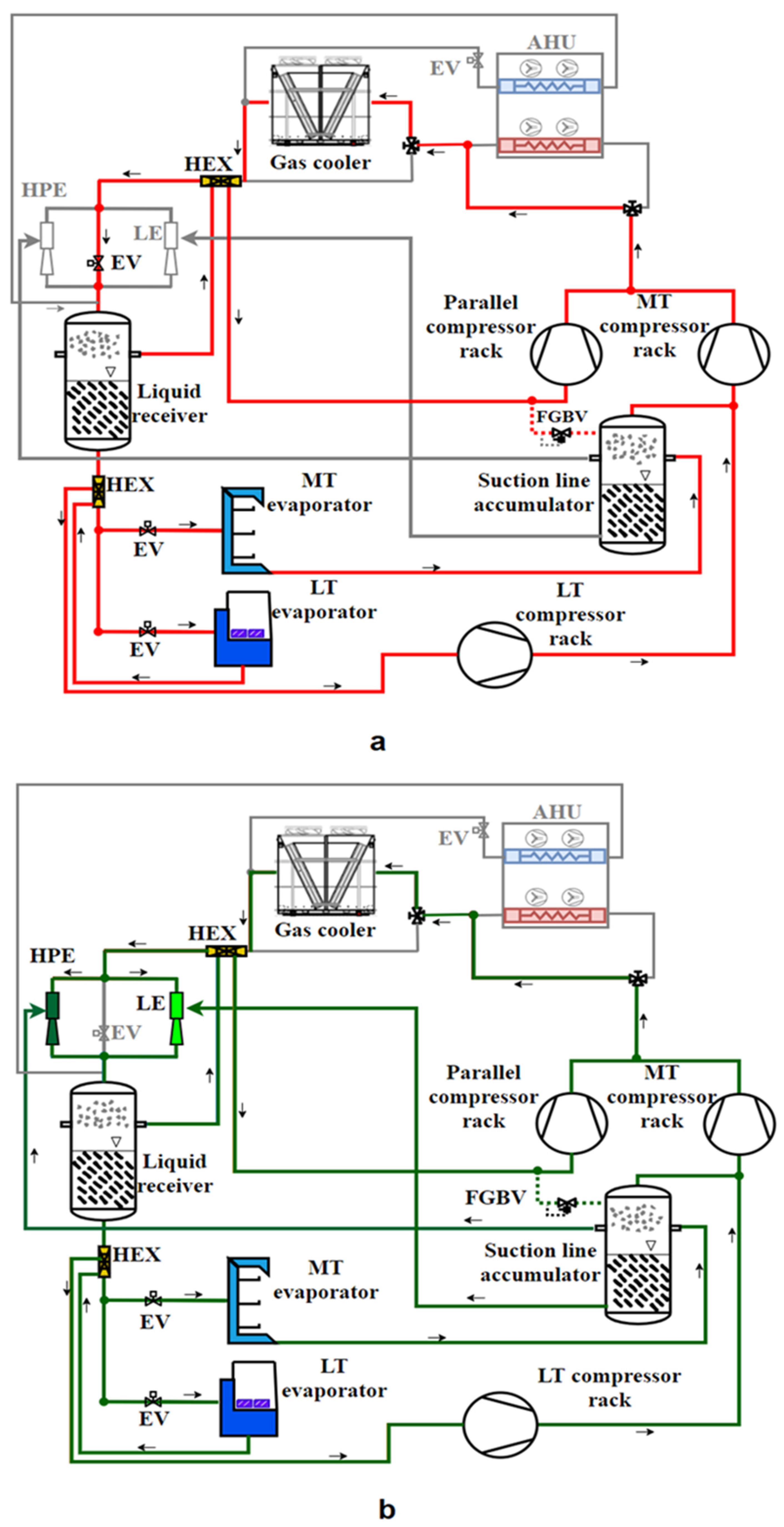
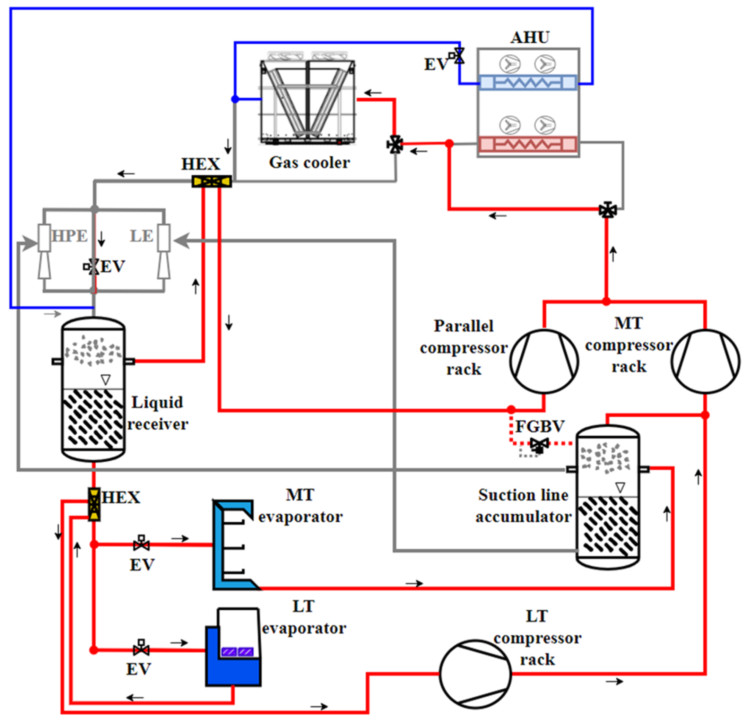
2.1. System Setup and Description

Despite being fully integrated, for the purpose of this work, the system performance is addressed only considering AC demand; owing to this, the layouts for heat pump mode, SH, and DHW are not covered in detail in the following sections; however, they are described in [21]. The system is based on a booster system with parallel compression, where the HPE can unload the parallel and MT compressors. Further, the application of the LE enables the lift of the MT evaporation temperature and flooded MT evaporators. Two operation modes will be investigated in particular:
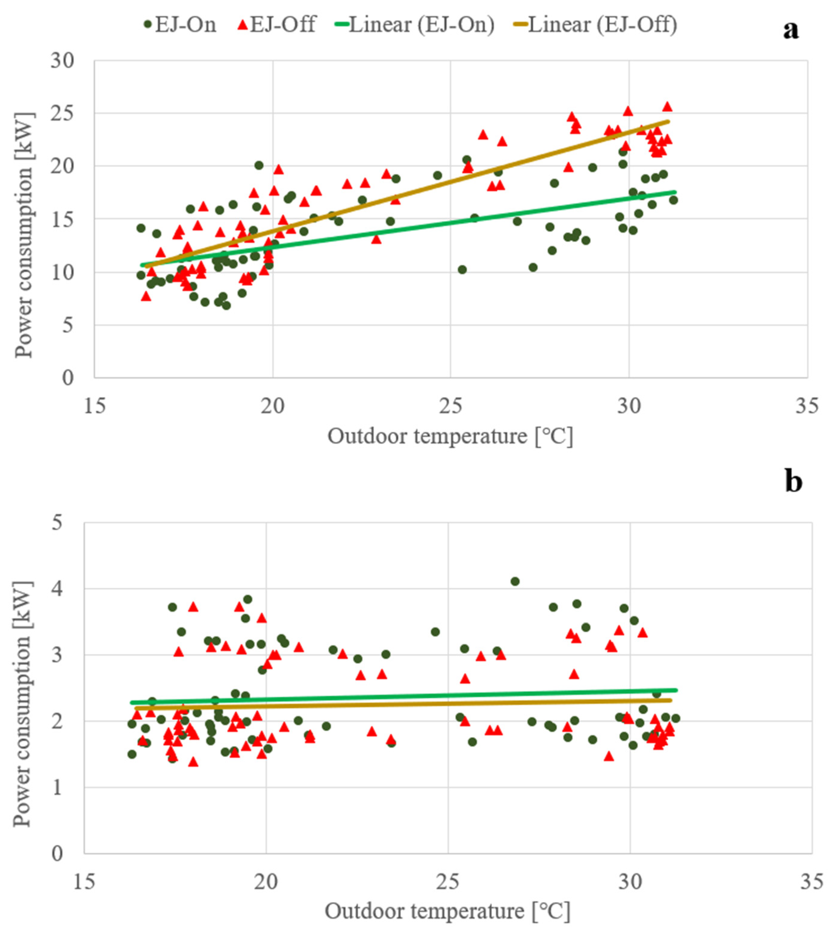
  • EJ-On mode: Both ejectors are in operation for LT and MT cooling demand.
  • EJ-Off mode: The system operates in LT and MT cooling mode; however, the ejectors are not in operation.
The schematic diagram of the system for these modes is shown in Figure 1 (depicted with a colorful line).
The system can meet AC demand by direct evaporation in the air handling units (AHUs) units. Due to the summer season and warm ambient temperatures, AC is applied to meet the temperature set-point inside the shop (Figure 2). Moreover, compressor racks and AHU units are shown only with a single symbol.
The system consists of the LT compressor rack (three semi-hermetic compressors), the MT compressor rack (four semi-hermetic compressors), and the parallel compressor (PC) rack (four semi-hermetic compressors) for AC; a gas cooler (GC); MEs; liquid receiver, MT suction line accumulator; LT and MT evaporators, expansion valves (EVs), oil recovery system, and two rooftop AHUs.
For each compressor rack, one compressor is equipped with an inverter to allow smoother capacity modulation. The PCs are organized in such a way that they can manage different suction pressures according to heat pump functionality and/or PC. The ME blocks were sized for vapor pre-compression (HPE) according to the climate profile of the region and liquid return (LE) in the case of liquid leaving the MT evaporators.
The AHU comprises two identical rooftop units. These units deliver the entire heating and cooling capacity of the supermarket. CO2 is directly applied inside the heating and cooling coils of the AHUs. SH demand can be covered seamlessly by means of a 3-way valve allowing high pressure CO2 gas supply to the heating coils in the AHU. An increasing high pressure and separate heat pump functionality can be utilized to cover high heating demands. In summertime, the AHU’s cooling coils can be operated in two different ways: the first alternative is the DX downstream of the GC, i.e., the refrigerant expands from the high-pressure side directly into the coils where it is evaporated and enters the liquid receiver. The second alternative is using a low-pressure lift high entrainment ratio ejector (AC ejector). The AC ejector sucks the whole vapor of the AC evaporators to compress it to the receiver pressure level. The first alternative was in operation during the time period analyzed in this study; thus, the effect of AC ejectors will not be mentioned in the following sections.
High-pressure lift and liquid ejectors are applied to return both vapor and liquid from the suction line accumulator to the liquid receiver.
To assess the effect of the ejectors, at first, the ejectors were not activated (EJ-Off mode) to collect field measurement data for the benchmark performance. The cycle configuration and flow directions are displayed in Figure 1a. The vapor is compressed by the MT compressor rack before entering the GC. The cooled high-pressure CO2 bypasses the ejectors and expands through HPV to the liquid receiver pressure. In the liquid receiver, the refrigerant is separated into the vapor and liquid phases. The liquid refrigerant is supplied through the EVs upstream of the LT evaporator (freezing cabinets, freezing rooms, etc.) and MT evaporators (cold rooms, open and closed cabinets, fresh meat, and fish cabinets). The vapor downstream of the MT evaporators is collected in the suction line accumulator. The vapor downstream of the LT evaporator is first superheated by a heat exchanger located downstream of the liquid receiver before entering the LT compressor rack. The vapor is compressed to the MT pressure level and mixed with the vapor coming from the suction line accumulator before entering the MT compressor rack.
In the EJ-On mode, the overall layout is similar to the EJ-Off mode’s; however, downstream of the GC, the refrigerant is expanded via the ejectors, i.e., expansion work recovery is utilized. The ejectors transfer vapor and liquid from the suction line accumulator to the liquid receiver (Figure 1b).
While meeting the demand on the LT and MT sides, the refrigeration system also fulfils the demand for space cooling simultaneously. As illustrated in Figure 2, for the case of AC demand, a part of the cold high-pressure gas downstream of the GC is expanded directly into the evaporators inside the AHU. Downstream of the evaporators, the refrigerant enters the liquid receiver, and the vapor is sucked by the PC rack.
COP has traditionally been used as an indicator of the efficiency of a dedicated refrigeration or heat pump system; it also enables comparison between various system designs. Here, the unit we are analyzing is an integrated cooling (multiple evaporation temperature levels) and heating (indoor heating and hot water) system with energy recovery components. Accordingly, the use of the COP indicator is not as relevant. Energy consumption is a factor that accounts for the overall effect on the system and allows for the comparison of different weeks.

2.2. Measurements and Instrumentation

The system is equipped with measuring instruments for temperature, pressure, and compressor input power measurements. NTC (negative temperature coefficient) 10 kΩ sensors and piezoresistive pressure transmitters were used for temperature and pressure measurements, respectively. To evaluate the total electric power input, three-phase electric power meters are located before each compressor rack to measure the individual power input to LT, MT, and PCs. The status of every compressor and the inverter frequency are also acquired. The total power input to the system, including auxiliary components (fans, pumps, valve motors, etc.), is monitored. The measuring instruments used in the system are summarized in Table 2.

3. Results and Discussion

The power consumption levels from the field were analyzed for two different modes: both ejectors are on (EJ-On mode) or off (EJ-Off mode). Furthermore, the changes in system performance related to the activities within a day were also considered. Figure 3 shows the analyzed period for the two modes. The analysis was conducted in a period when the outdoor temperatures for both modes were at the same level. During the given periods, the variations in the outdoor temperatures within the day were between 15 and 31 °C. The measurement data for EJ-On mode were collected for the period from 31 July to 2 August 2020, while from 5 August to 8 August 2020 for the system was operated without ejectors (EJ-Off mode).

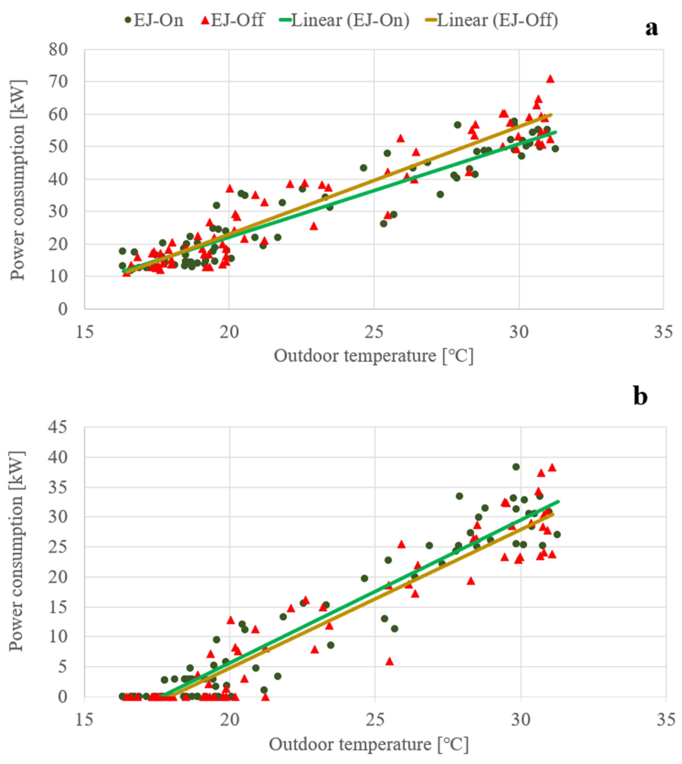
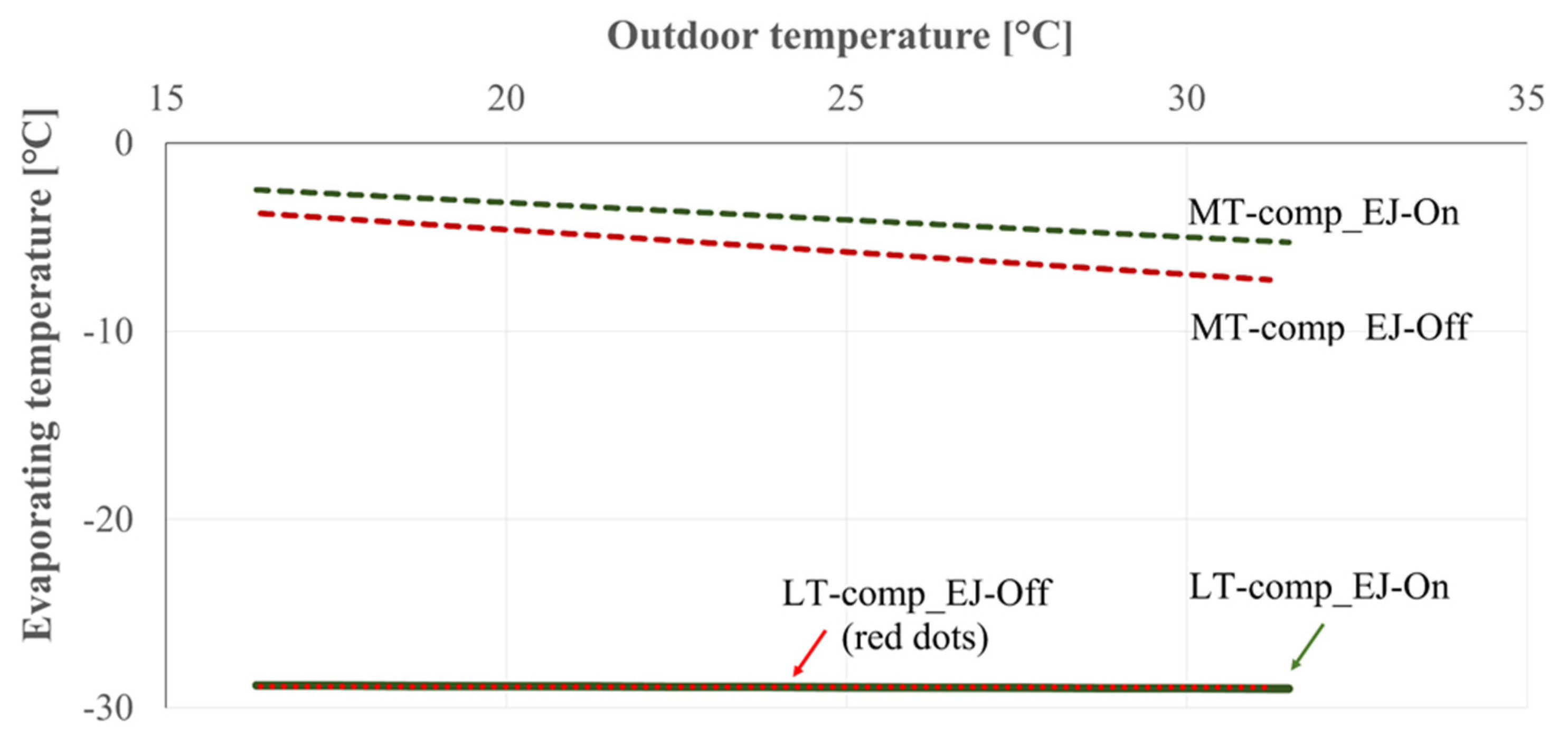
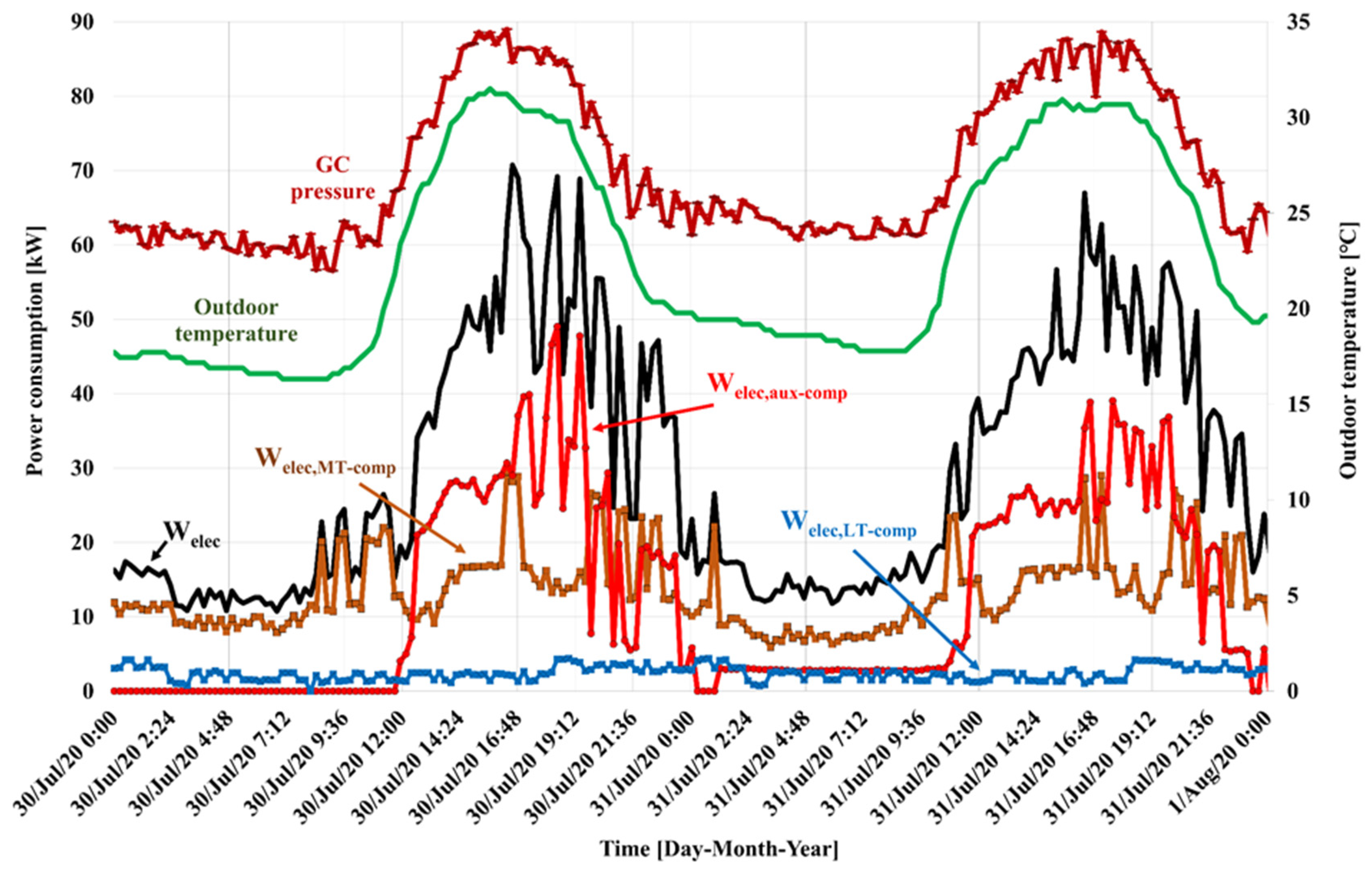
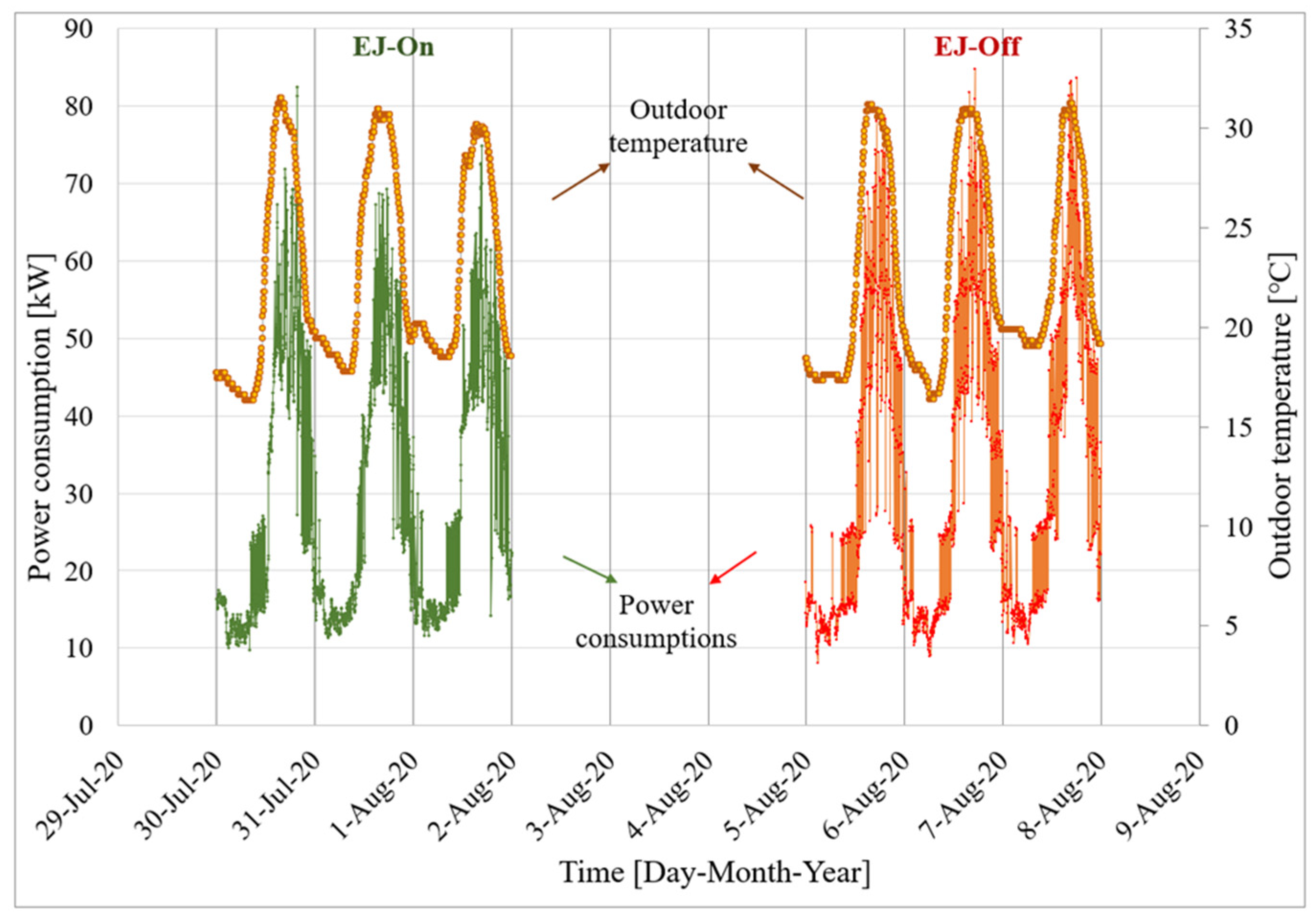
3.1. Power Consumption
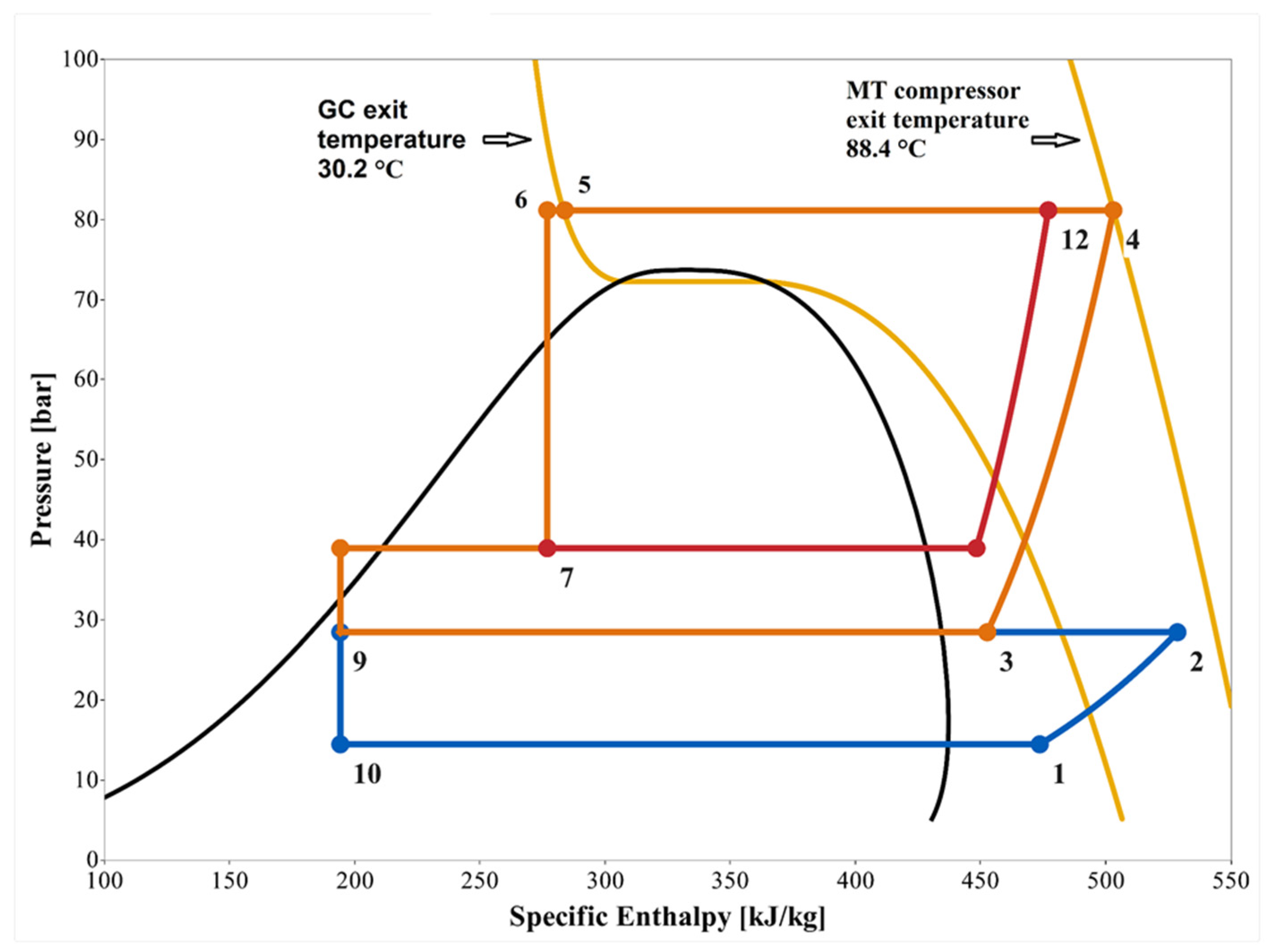
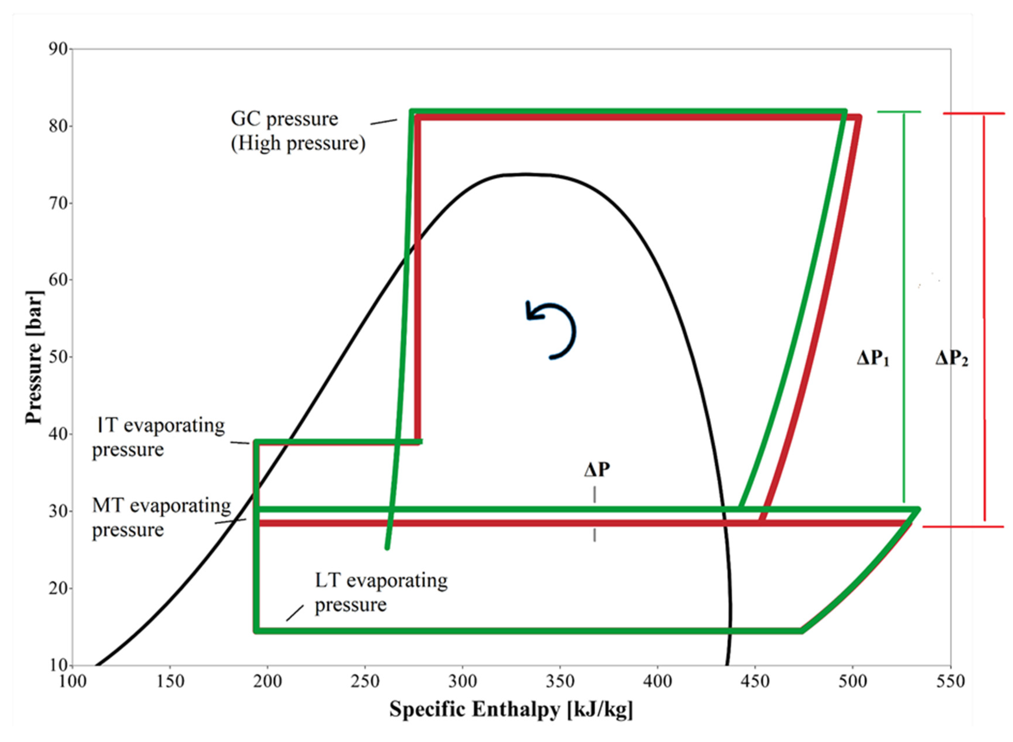
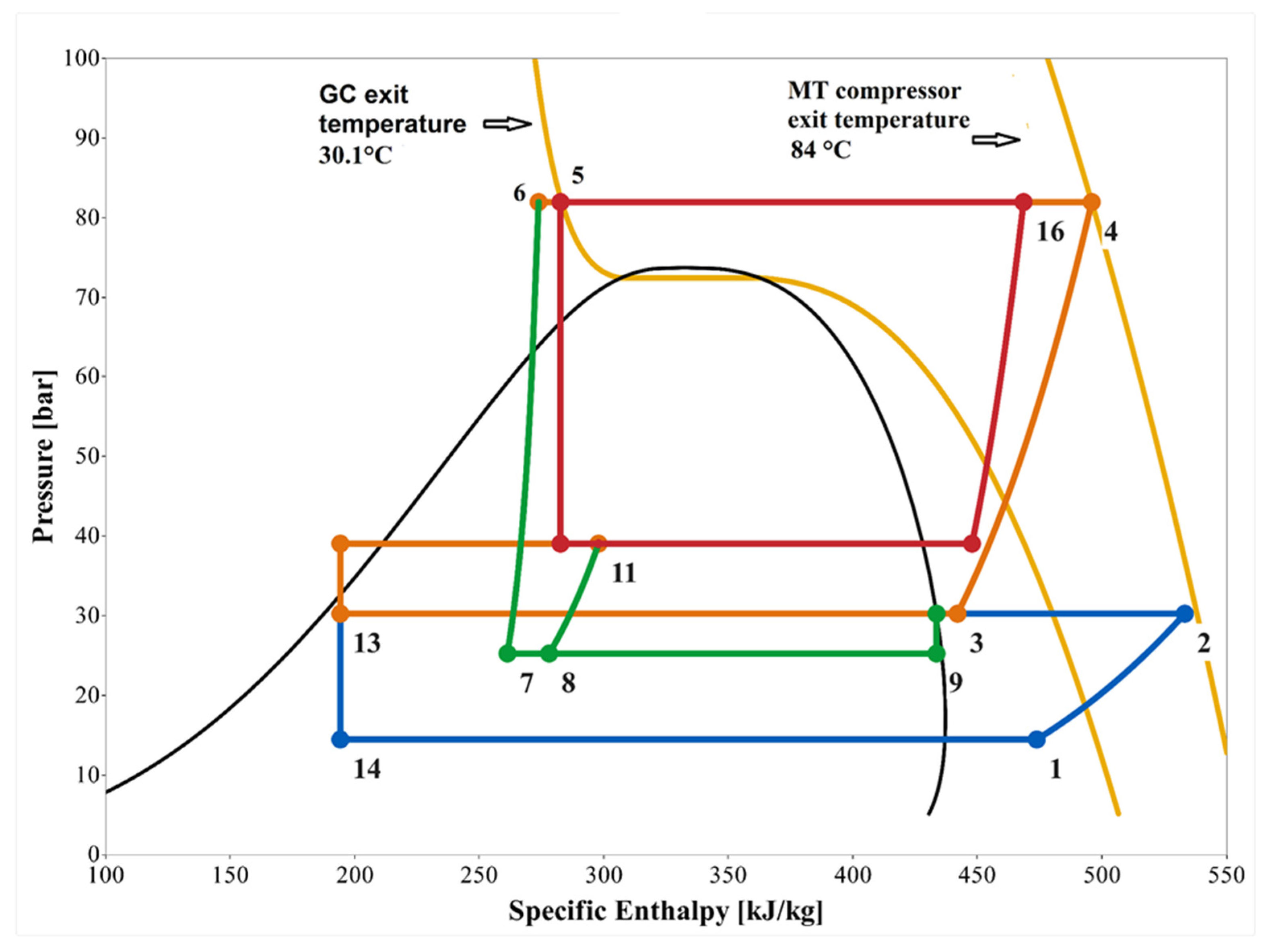
The power consumptions for the EJ-On and EJ-Off modes are shown in Figure 4 and Figure 5. The total power consumption, as well as the PC rack’s power consumption, are presented in Figure 4a,b, respectively. The power consumption of the MT and LT packs is shown in Figure 5a,b.
The total power consumption increases with the rising outdoor temperature for each mode. This is triggered particularly by (1) an increase in the cooling load at LT and MT side (refrigerators and open cabinets) due to the influence of the humidity and temperature inside the shopping area and (2) mainly due to the increase in heat rejection temperature at the GC, reducing the specific cooling capacity when expanding the refrigerant. The total power consumption in the EJ-Off mode is higher compared to the EJ-On mode. It is also clearly seen in Figure 4a that the system with the ejectors performs well at all outdoor temperatures. However, the PC rack’s power consumption is higher in the EJ-On mode since the system has a higher workload in the EJ-On mode compared to the EJ-off mode. When the ejectors are in operation, they unload the MT compressors by transferring CO2 from the MT suction level toward the PC suction level.
For the MT, in the EJ-On mode, the MT compressors consume less power compared with the EJ-Off mode, as seen in Figure 5a. Additionally, in this figure, the ejectors’ positive effect on the system performance can plainly be seen; less power is consumed at higher outdoor temperatures with the ejectors. In terms of the LT side (Figure 5b), the power consumption at the two modes is almost identical. In the EJ-On mode, the power consumption is higher than that of EJ-Off at an outdoor temperature of above 25 °C.
In Table 3, the average power consumption values and their total uncertainties in the given operation periods are listed. The total uncertainties were calculated by considering random (the standard deviation of the mean) and systematic (sensor uncertainty) uncertainties [24]. The fundamental power consumers are MT and PC racks for both modes. The share of MT compressor rack consumption is roughly 51% in the EJ-Off mode, whereas it is just above 45% in the EJ-On mode. In other words, the HP ejector unloads the MT compressors. The power consumption share of PC racks is 35% and 40% at EJ-Off and EJ-On, respectively. The rest of the components have a share of below 8%.
The main contributors for a reduction of the total power consumption at similar cooling demands are the MT compressor rack in the EJ-On mode. The average power consumption for the MT compressor rack in the EJ-On mode is 17.4% less than that in the EJ-Off mode. The power demand for the PC rack increased as the ejectors unloaded the MT compressors. However, the total average power consumption in the EJ-On mode was 7.5% lower compared to the EJ-Off mode at similar load and ambient temperatures (between 15 and 31 °C).
As shown in Figure 6, the key factor for the lower power consumption of the MT compressor rack in the EJ-On mode is its higher evaporating temperature level, on average by 1.7 K, compared to the EJ-Off mode. It is worth mentioning that the MT side evaporating temperature at EJ-On mode has a slight decrease over increasing outdoor temperature. This is due to the control of evaporating pressure to maintain the cabinet temperature. On the contrary, there is a more apparent decline in the MT side evaporating temperature of the EJ-Off mode.
In Table 4, the daily average power consumptions at above 25 °C are listed in detail. According to the average three-day data, the total average power consumption in the EJ-On mode was approximately 11% lower compared to the EJ-Off mode. The PC rack has the highest share in energy demand; around half of the total average energy was consumed in the EJ-Off mode and nearly 60% in the EJ-On mode. The power consumption for the PC rack at EJ-On mode is 4.1% higher than that in the EJ-Off mode. However, the MT compressor rack power consumption in the EJ-On mode is almost 30% lower in comparison with the EJ-Off mode. The MT side evaporating temperature of the EJ-On mode is 2.3 K higher than that of EJ-Off. In terms of GC fan and LT compressor rack power consumption, their share in total consumption is under 10% at both modes. LT compressor rack power consumption is almost identical for both modes, but the GC fan’s power consumption at EJ-On mode is nearly 30% less compared to the EJ-Off mode.

3.2. P-h Diagrams

A P-h (pressure-specific enthalpy) diagram allows insight into how a refrigeration system works and its working conditions. The P-h diagrams based on average measurements for the systems are shown in Figure 7, Figure 8 and Figure 9 for above a 25 °C outdoor temperature (on average 29.0 ± 1 °C). The calculations were made by means of REFROP-NIST Reference Fluid Properties (DLL version 10.0), and the cycles were created via DaVE (TLK-Thermo GmbH, Version 1.7.0).
Figure 7 represents the working conditions for EJ-Off mode, while Figure 8 shows for EJ-On mode. LT and IT side pressure of both modes are identical, 14.5 bar and 39.0 bar, respectively. The GC pressures at EJ-Off and EJ-On mode are similar at 81.2 bar and 82.0 bar, respectively. GC outlet temperatures for both modes are 30 ± 1 °C, about 1K above ambient temperature. Additionally, the MT compressor exit temperature at EJ-Off mode is 88.4 °C and at EJ-On is 84 °C. In both modes, the temperature difference between the compressor exits and the GC exits is above 50 °C. Excess heat is used to produce hot water for space heating and domestic usage.
The lower power input of MT compressors at the EJ-On mode compared to the EJ-Off mode is triggered by higher evaporating temperature and pressure, as presented in Figure 9. The pressure difference between GC pressure and MT evaporating pressure for EJ-On (ΔP1) is lower than that for EJ-Off (ΔP2). The MT pressure difference between the two modes (ΔP) is approximately 2 bar. Although this pressure difference causes a slight increment in the power input of LT compressors in the EJ-On mode, it significantly increases MT compressors’ performance.

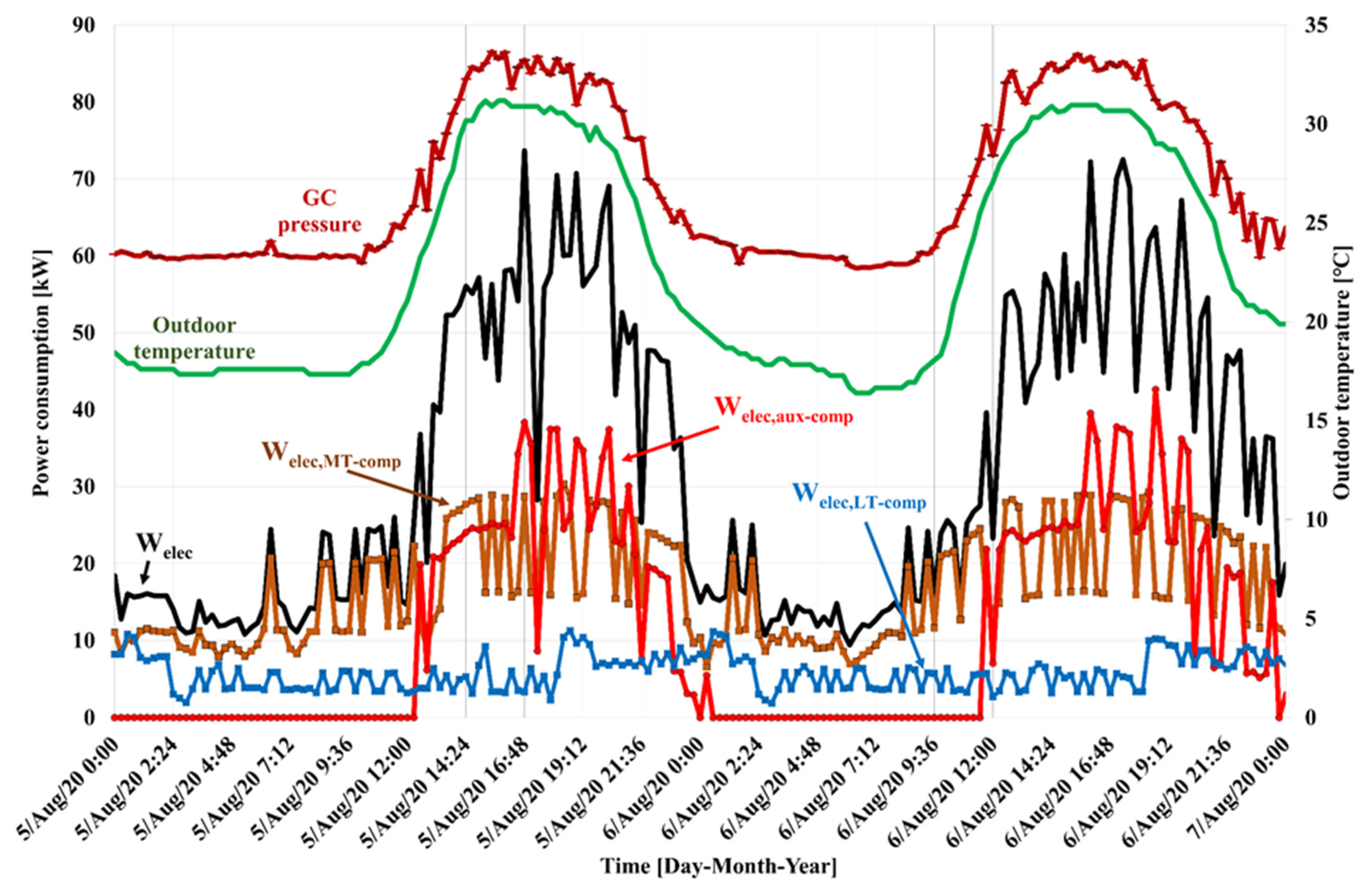
3.3. Daily Activity in the Supermarket

In Figure 10 and Figure 11, two-day detailed data show the electrical power consumptions, GC pressures, and outdoor temperatures over time for two modes.
The opening hours of the supermarket range from 8:00 to 22:00. As seen from the figures, the power consumption is lower between 00:00 and 8:00 owing to lower outdoor temperatures and no human activities in the shop. During this period of the day, the total power consumption ranges between 10 kW and 30 kW. The main contributor to consumption is the MT compressors, followed by the LT compressors. PCs are not in operation. EJ-On mode has less power consumption than the EJ-Off mode within the same period. Power consumption starts increasing just after the opening of the shop and reaches a maximum value of up to 30 kW between 8:00 and 12:00.
There is a sharp rise in total power consumption at around 12:00 and then peaks between 16:00 and 18:00. The driving factor of this peak is parallel compressors’ activation due to the high demand for space cooling with rising outdoor temperatures. In summer operations, when the outdoor temperatures are higher, the heat needs to be removed through GC. Therefore, GC pressure is also getting higher as the outdoor temperature increases. The other factor for peak consumption is higher heating loads led by operational conditions/human activities (according to the information collected from the supermarket where the system is installed, the busiest time is between 16:00 and 18:00). The reason is that there is an increase in door opening frequencies of the closed cabinets and a higher warm air infiltration into the cooling and freezing cabinets within the shop. This causes a higher compressor working time and therefore higher power consumption [25,26]. The increment in LT and MT compressor power consumption is seen in Figure 10 and Figure 11. It is noteworthy to state that MT compressor average power consumption at EJ-On mode (17.6 kW) is less by roughly 23% than that of the EJ-Off mode (22.8 kW) during the busiest period. The total average power consumptions for EJ-On and EJ-Off modes are 53.9 kW and 61.7 kW, respectively, with approximately 13% difference, within the same period of time.
The power consumption starts decreasing thereafter 18:00 until midnight (00:00) and approaches minimum consumption levels.

4. Conclusions

Well-informed and demanding shop owners interested in saving costs are choosing integrated energy systems for their supermarkets across the world. When the system layout is properly adopted, significant energy and cost savings can be obtained. Integrated system layout in this respect means that the centralized refrigeration unit delivers the entire freezing, cooling, and AC demand of the supermarket. Within the EU-funded project MultiPACK, a series of demonstration supermarkets are developed and monitored across Southern Europe.
In this work, one of the demonstration units in Portugal within the context of the MultiPACK project was analyzed. The target of the study was to demonstrate the energy demand of the CO2 system (including AC) by comparing the two different cases (the ejectors were on or off). A detailed analysis shows the different effects of ejectors in a real supermarket operational environment.
The field data for similar three days at corresponding ambient conditions and cooling demands showed that the total energy saving of the ejector system was 7.5% compared to a parallel compression system. At equal or above 25 °C outdoor temperatures, the total energy saving increases to up to 11%. The main contributors to this result are the load shift from MT to the parallel compressors and higher evaporation temperature (around 1.7 K) enabled due to ejector operation. The average energy savings for three consecutive days on the MT side is 17.4% with ejector operations, while the savings are almost 30% at outdoor temperatures equal to or greater than 25 °C.
The behavior of electrical power consumption, GC pressure, and outdoor temperature within a day has also been analyzed. According to the detailed daily data, the power consumption of the installed system peaks between 16:00 and 18:00. The driving factor of this peak is the parallel compressors’ activation due to the high demand for space cooling with the highest outdoor temperatures. The other factor for peak consumption in this period is the high number of customers. It has been determined that, between 16:00 and 18:00, MT compressor average power consumption at EJ-On mode is 17.6 kW, which is reduced by almost 23% compared to that of EJ-Off mode (22.8 kW). The total average power consumption for EJ-On is 53.9 kW, which is approximately 13% lower compared to the EJ-Off mode (61.7 kW), within the same period of time.

Author Contributions

Conceptualization, E.S. and A.H.; methodology, E.S. and A.H.; formal analysis, E.S., A.H., C.S. and E.E.K.; investigation, E.S.; resources, E.S.; data curation, C.S.; writing—original draft preparation, E.S.; writing—review and editing, E.S., A.H., C.S., E.E.K. and V.K.; visualization, E.S.; supervision, A.H.; project administration, A.H.; funding acquisition, A.H. All authors have read and agreed to the published version of the manuscript.

Funding

This project received funding from the European Union’s Horizon 2020 research and innovation programme under grant agreement No 723137.

Institutional Review Board Statement

Not applicable.

Informed Consent Statement

Not applicable.

Data Availability Statement

The data supporting reported results can be found here: https://doi.org/10.18710/J9BQLO.

Conflicts of Interest

The authors declare no conflict of interest.

Abbreviations

ACAir Conditioning
AHUAir Handling Unit
BRSBooster Refrigeration System
DHWDomestic Hot Water
DXDirect Expansion
EVExpansion Valve
FEFlooded Evaporator
FSFull Scale
HEXHeat Exchanger
HFCHydrofluorocarbon
HFONon-Saturated Hydro Fluorocarbon
HPHigh-Pressure
HPEHigh-Pressure Ejector
ITIntermediate Temperature
IHXInternal Heat Exchanger
LELiquid Ejector
LTLow Temperature
MMass Flow Meters
MEMulti-Ejector
MTMedium Temperature
NTCNegative Temperature Coefficient
PCParallel Compressor
SHSpace Heating

References

  1. Skačanová, K.Z.; Gkizelis, A. Climate—Technical Report on Energy Efficiency in HFC-Free Supermarket Refrigeration; EIA and Shecco: London, UK, 2018. [Google Scholar]
  2. Koegelenberg, I. World Guide to Transcritical CO2 Refrigeration; Shecco: Brussels, Belgium, 2020. [Google Scholar]
  3. Gullo, P.; Hafner, A.; Banasiak, K. Transcritical R744 refrigeration systems for supermarket applications: Current status and future perspectives. Int. J. Refrig. 2018, 93, 269–310. [Google Scholar] [CrossRef]
  4. Gullo, P.; Hafner, A.; Banasiak, K.; Minetto, S. A review on recent technological advancements in multi-ejector concept. In Proceedings of the 13th IIR Gustav Lorentzen Conference on Natural Refrigerants (GL2018), Valencia, Spain, 18–20 June 2018; International Institute of Refrigeration: Paris, France, 2018. [Google Scholar]
  5. Tsamos, K.M.; Ge, Y.T.; Santosa, I.D.; Tassou, S.A.; Bianchi, G.; Mylona, Z. Energy analysis of alternative CO2 refrigeration system configurations for retail food applications in moderate and warm climates. Energy Convers. Manag. 2017, 150, 822–829. [Google Scholar] [CrossRef]
  6. Mitsopoulosa, G.; Syngounasa, E.; Tsimpoukisa, D.; Bellosa, E.; Tzivanidisa, C.; Anagnostatos, S. Annual performance of a supermarket refrigeration system using different configurations with CO2 refrigerant. Energy Convers. Manag. 2019, X1, 100006. [Google Scholar] [CrossRef]
  7. Suna, Z.; Lia, J.; Liangb, Y.; Suna, H.; Liua, S.; Yanga, L.; Wanga, C.; Dai, B. Performance assessment of CO2 supermarket refrigeration system in different climate zones of China. Energy Convers. Manag. 2020, 208, 112572. [Google Scholar]
  8. Cui, Q.; Gao, E.; Zhang, Z.; Zhang, X. Preliminary study on the feasibility assessment of CO2 booster refrigeration systems for supermarket application in China: An energetic, economic, and environmental analysis. Energy Convers. Manag. 2020, 225, 113422. [Google Scholar] [CrossRef]
  9. Karampour, M.; Sawalha, S. State-of-the-art integrated CO2 refrigeration system for supermarkets: A comparative analysis. Int. J. Refrig. 2018, 86, 239–257. [Google Scholar] [CrossRef] [Green Version]
  10. Maourisa, G.; Escrivab, E.J.S.; Achaa, S.; Shaha, N.; Markides, C.N. CO2 refrigeration system heat recovery and thermal storage modelling for space heating provision in supermarkets: An integrated approach. Appl. Energy 2002, 264, 114722. [Google Scholar] [CrossRef]
  11. Polzota, A.; Agaroa, P.D.; Cortellaa, G. Energy analysis of a transcritical CO2 supermarket refrigeration system with heat recovery. Energy Procedia 2017, 111, 648–657. [Google Scholar] [CrossRef] [Green Version]
  12. Escriva, E.J.S.; Acha, S.; Le Brun, N.; Francés, V.S.; Ojer, J.M.P.; Markides, C.; Shah, N. Modelling of a real CO2 booster installation and evaluation of control strategies for heat recovery applications in supermarkets. Int. J. Refrig. 2019, 107, 288–300. [Google Scholar] [CrossRef]
  13. D’Agaro, P.; Cortella, G.; Polzot, A. R744 booster integrated system for full heating supply to supermarkets. Int. J. Refrig. 2018, 96, 191–200. [Google Scholar] [CrossRef]
  14. Cooling, A.-A.C. Food Retail Best Practices; Shecco: Bruxelles, Belgium, 2020. [Google Scholar]
  15. Hafner, A.; Försterling, S.; Banasiak, K. Multi-ejector concept for R-744 supermarket refrigeration. Int. J. Refrig. 2014, 43, 1–13. [Google Scholar] [CrossRef]
  16. Karampour, M.; Sawalha, S. Energy efficiency evaluation of integrated CO2 trans-critical system in supermarkets: A field measurements and modelling analysis. Int. J. Refrig. 2017, 82, 470–486. [Google Scholar] [CrossRef] [Green Version]
  17. Gullo, P.; Tsamos, K.; Hafner, A.; Ge, Y.; Tassou, S.A. State-of-the-art technologies for transcritical R744 refrigeration systems—A theoretical assessment of energy advantages for European food retail industry. Energy Procedia 2017, 123, 46–53. [Google Scholar] [CrossRef]
  18. Singh, S.; Maiya, P.M.; Hafner, A.; Banasiak, K.; Neksa, P. Energy efficient multiejector CO2 cooling system for high ambient temperature. Therm. Sci. Eng. Prog. 2020, 19, 100590. [Google Scholar] [CrossRef]
  19. Gullo, P.; Hafner, A.; Cortella, G. Multi-ejector R744 booster refrigerating plant and air conditioning system integration—A theoretical evaluation of energy benefits for supermarket applications. Int. J. Refrig. 2017, 75, 164–176. [Google Scholar] [CrossRef]
  20. Pardiñas, A.A.; Hafner, A.; Banasiak, K. Novel integrated CO2 vapour compression racks for supermarkets. Thermodynamic analysis of possible system configurations and influence of operational conditions. Appl. Therm. Eng. 2018, 131, 1008–1025. [Google Scholar]
  21. Schlemminger, C.; Bjørgen, K.O.P.; Foslie, S.; Allouche, Y.; Hafner, A. Field measurements of integrated MultiPACK supermarkets. In Proceedings of the 6th IIR Conference on Sustainability and the Cold Chain, Nantes, France, 26–28 August 2020. [Google Scholar]
  22. Tosato, G.; Minetto, S.; Hafner, A.; Rossetti, A.; Marinetti, S.; Girotto, S. Field assessment of the performance of a state-of-the-art CO2 integrated system for supermarket with distributed HVAC terminals in the shopping area. In Proceedings of the 6th IIR Conference on Sustainability and the Cold Chain, Nantes, France, 26–28 August 2020; pp. 26–28. [Google Scholar]
  23. Minetto, S.; Tosato, G.; Rosetti, A.; Marinetti, S.; Girotto, S.; Banasiak, K. Not-in-kind approach to remote monitoring in CO2 refrigeration systems. In Proceedings of the 25th IIR International Congress of Refrigeration, Montréal, QC, Canada, 24–30 August 2019; International Institute of Refrigeration: Paris, France, 2019. [Google Scholar]
  24. Taylor, J.R.; Thompson, W. An Introduction to Error Analysis: The Study of Uncertainties in Physical Measurements. Phys. Today 1998, 51, 57–58. [Google Scholar] [CrossRef] [Green Version]
  25. Chaomuang, N.; Flick, D.; Denis, A.; Laguerre, O. Influence of operating conditions on the temperature performance of a closed refrigerated display cabinet. Int. J. Refrig. 2019, 103, 32–41. [Google Scholar] [CrossRef]
  26. De Frias, J.A.; Luo, Y.; Zhou, B.; Zhang, B.; Ingram, D.T.; Vorst, K.; Brecht, J.K.; Stommel, J. Effect of door opening frequency and duration of an enclosed refrigerated display case on product temperatures and energy consumption. Food Control. 2019, 111, 107044. [Google Scholar] [CrossRef]
Figure 1. Simplified schematic diagram of the system: (a) EJ-Off mode/ordinary parallel compression mode, (b) EJ-On mode, no AC.
Energies 15 03142 g001
Figure 2. Simplified schematic diagram of the system: AHU cooling (the simultaneous operation of LT, MT, and AC).
Energies 15 03142 g002
Figure 3. The analyzed period for the two modes.
Energies 15 03142 g003
Figure 4. (a) The total power consumption, (b) the PC rack’s power consumption.
Energies 15 03142 g004
Figure 5. (a) The power consumption of the MT pack, (b) the power consumption of the LT pack.
Energies 15 03142 g005
Figure 6. Evaporating temperature of MT and LT evaporators.
Energies 15 03142 g006
Figure 7. P-h diagram for EJ-Off. 1–2: compression at LT compressors, 3–4: compression at MT compressors, 4–5: heat removal through GC, 5–6 subcooling, 6–7 expansion to IT pressure, 7–8 liquid refrigerant from the receiver to evaporators, 8–9: expansion to MT pressure, 8–10: expansion to LT pressure; 9–3: evaporation at MT evaporator, 10–1: evaporation at LT evaporator, 7–11 gas refrigerant from the liquid receiver to PCs, 11–12: compression at parallel compressors.
Energies 15 03142 g007
Figure 8. P-h diagram for EJ-On. 1–2: compression at LT compressors, 3–4: compression at MT compressors, 4–5: heat removal through GC, 5–6 subcooling, 6–7 isentropic expansion to IT pressure via HPE, 7–9 mixing in HPE, 10–9 vapour refrigerant from suction line accumulator to HPE nozzle inlet, 11–12 liquid refrigerant from the receiver to evaporators, 12–13: expansion to MT pressure, 12–14: expansion to LT pressure; 13–3: evaporation at MT evaporator, 14–1: evaporation at LT evaporator, 11–15 vapour refrigerant from the liquid receiver to PCs, 15–16: compression at parallel compressors.
Energies 15 03142 g008
Figure 9. Comparison of pressure levels of both modes (Dark green and red line represent EJ-On and EJ-Off modes, respectively). Due to interference, the lines at LT and IT pressure for the EJ-Off mode cannot be seen).
Energies 15 03142 g009
Figure 10. The behavior of electrical power consumptions, GC pressure, and outdoor temperature over time: EJ-Off.
Energies 15 03142 g010
Figure 11. The behavior of electrical power consumptions, GC pressure, and outdoor temperature over time: EJ-On.
Energies 15 03142 g011
Table 1. Installed capacities for the supermarket.
DemandOperating
Temperature
(°C)
Capacity
(kW)
Remark for the Demand
LT cooling−3024Freezers, freezing rooms, and an ice machine
MT cooling−4100Cold rooms, open and closed cooling cabinets
AC cooling10180For space cooling
AC heating30160For space heating
Table 2. The instruments for measurements (FS: full scale).
MeasurementInstrumentPrecision/Accuracy
PressurePiezoresistive pressure transmitters±1% FS up to 60 bars
±4% FS up to 150 bars
TemperatureNTC 10 kΩ±0.5 °C at 25 °C
±1 °C between −40 °C and 90 °C
PowerThree-phase electric power meters±0.5 % FS
Table 3. Overview of average (energy demand three days/72 h) power consumption.
ComponentsEJ-OffEJ-On
Power
Consumption
(kW)
Share
(%)
Power
Consumption
(kW)
Share
(%)
Total32.5 ± 0.710030.1 ± 0.7100
GC fan2.3 ± 0.17.01.8 ± 0.15.9
PC rack11.4 ± 0.335.212.3 ± 0.340.8
MT compressor rack16.6 ± 0.250.913.7 ± 0.245.4
LT compressor rack2.2 ± 0.16.92.4 ± 0.17.9
Table 4. Daily average power consumption levels above 25 °C outdoor temperature (Uncertainties: For total = ±0.7; GC fan = ±0.1, PC rack = ±0.3; MT compressor rack = ±0.2 and LT compressor rack = ±0.1).
ComponentsEJ-OffEJ-On
Day 1Day 2Day 3AvgDay 1Day 2Day 3Avg
kWkWkWkWkWkWkWkW
Total53.252.355.553.650.046.047.547.9
GC fan2.72.22.52.52.11.91.21.7
PC rack25.725.628.226.529.325.927.527.6
MT compressor rack22.522.222.522.416.115.716.516.1
LT compressor rack2.42.32.22.32.52.42.42.4
Publisher’s Note: MDPI stays neutral with regard to jurisdictional claims in published maps and institutional affiliations.

