
A Novel Type of Wave Energy Converter with Five Degrees of Freedom and Preliminary Investigations on Power-Generating Capacity

Abstract
:1. Introduction
2. Theoretical Analysis
2.1. Mathematical Description
2.2. Diffraction Problem
2.3. Radiation–Diffraction Problem
2.4. Dynamics Equation
2.5. Power Calculation
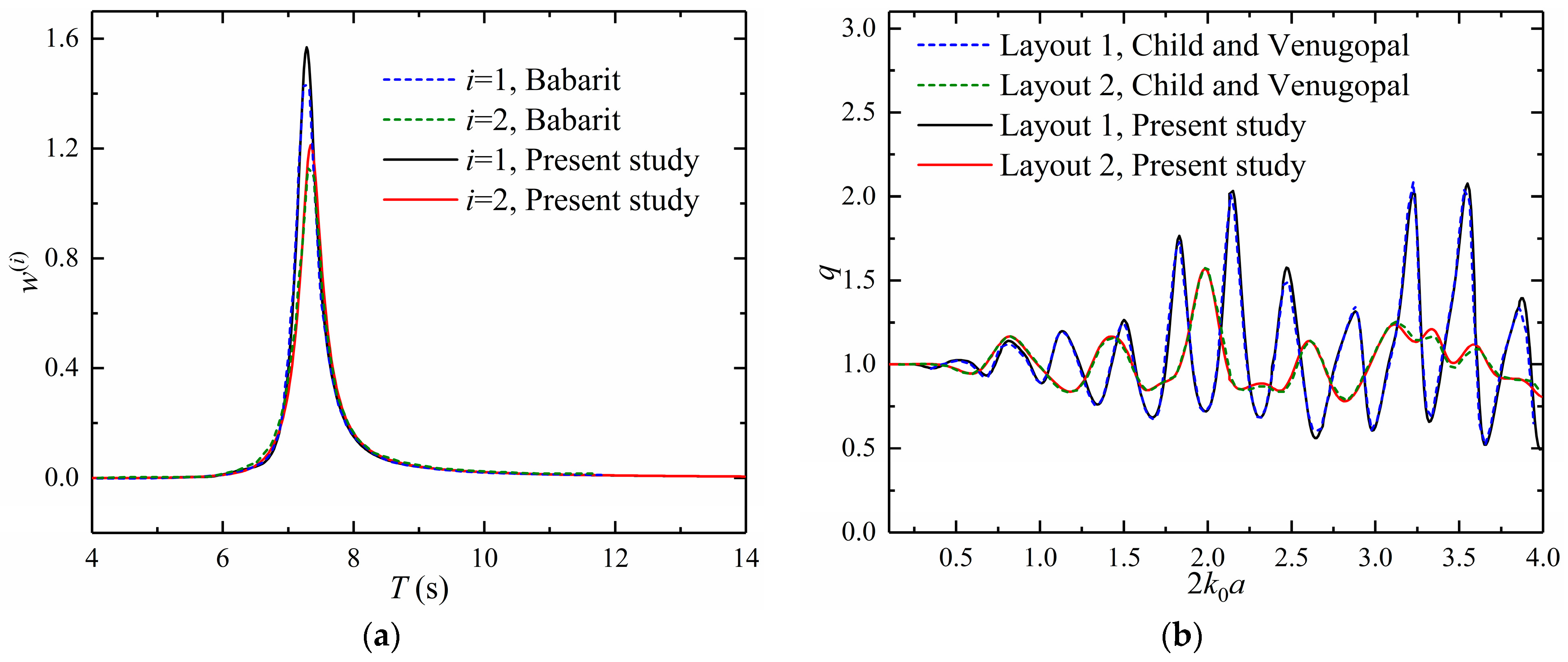
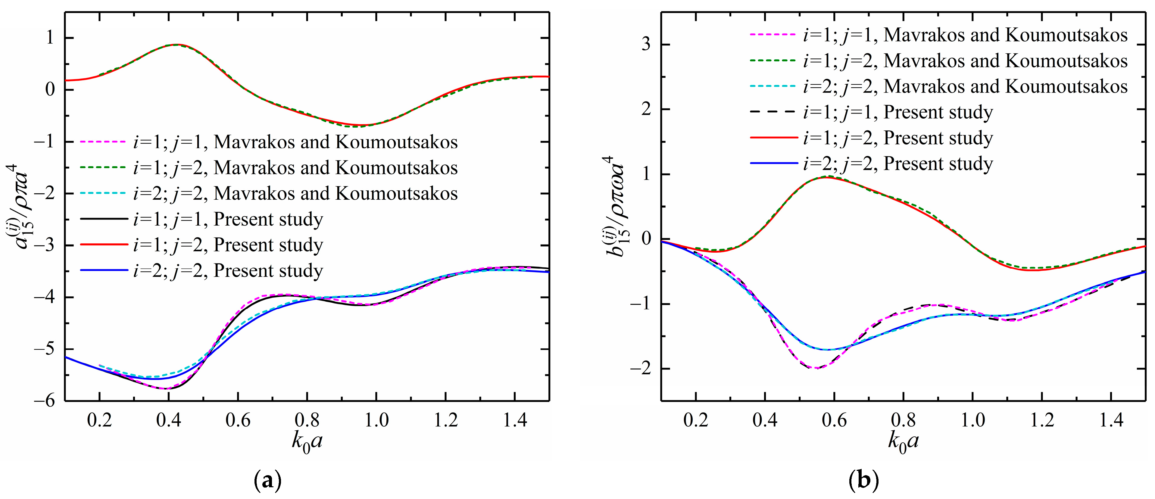
3. Validation
4. Results and Discussion
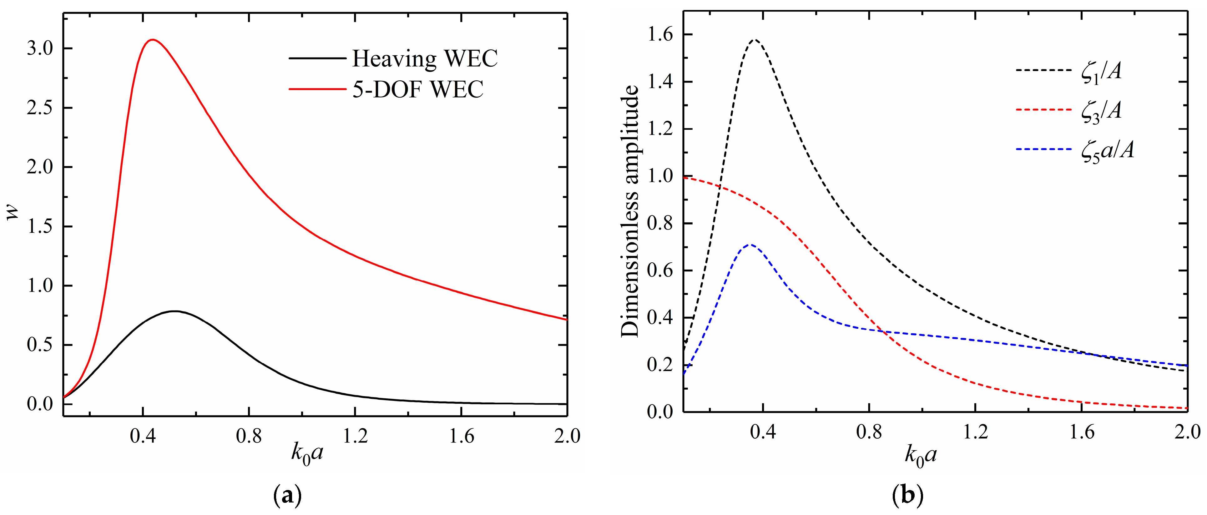
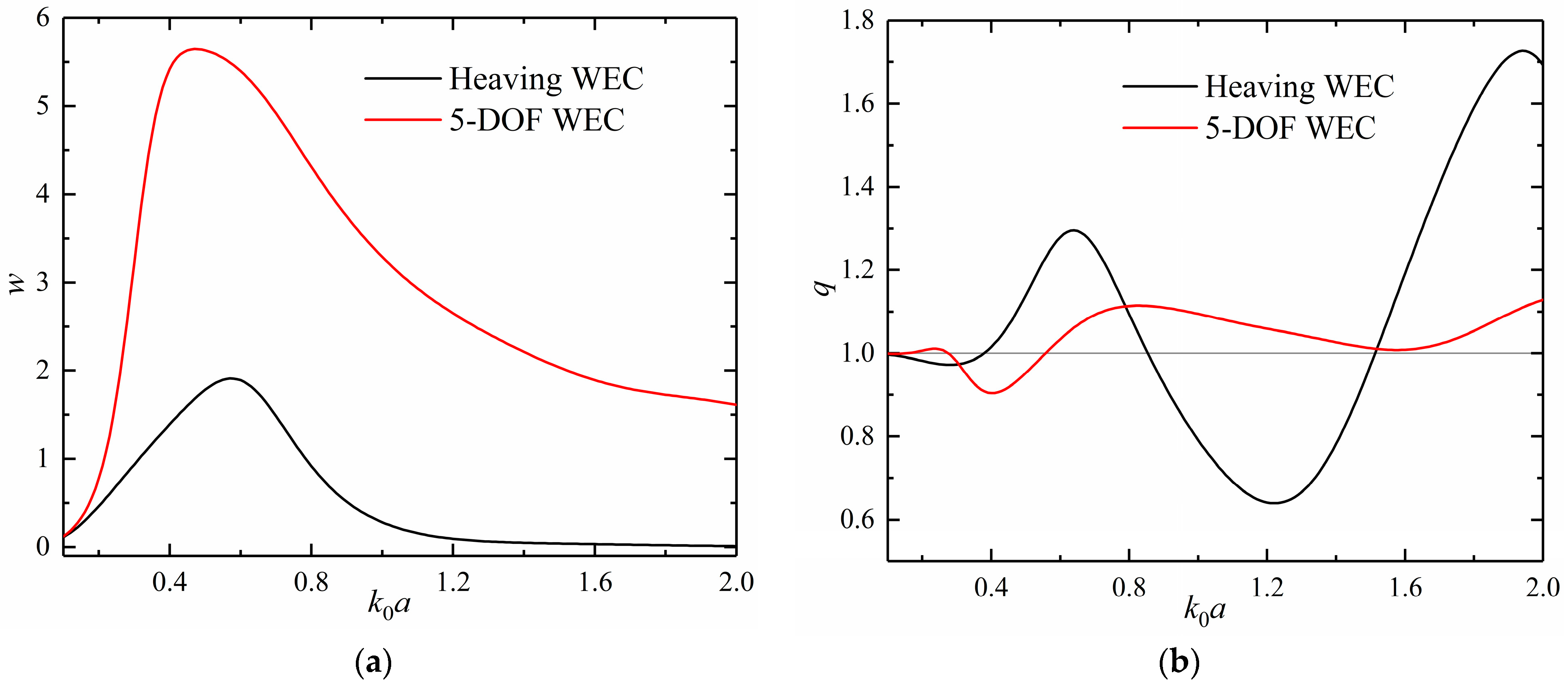
4.1. An Isolated WEC
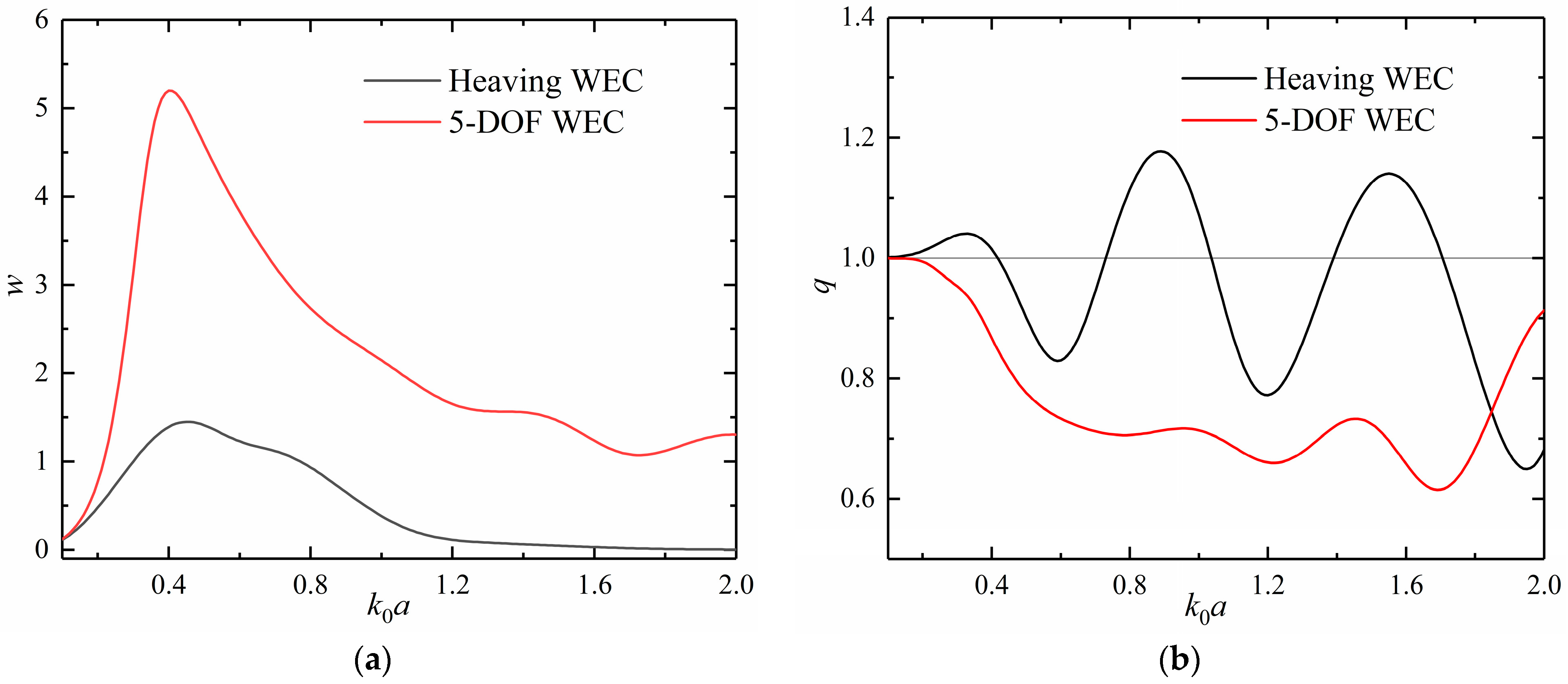
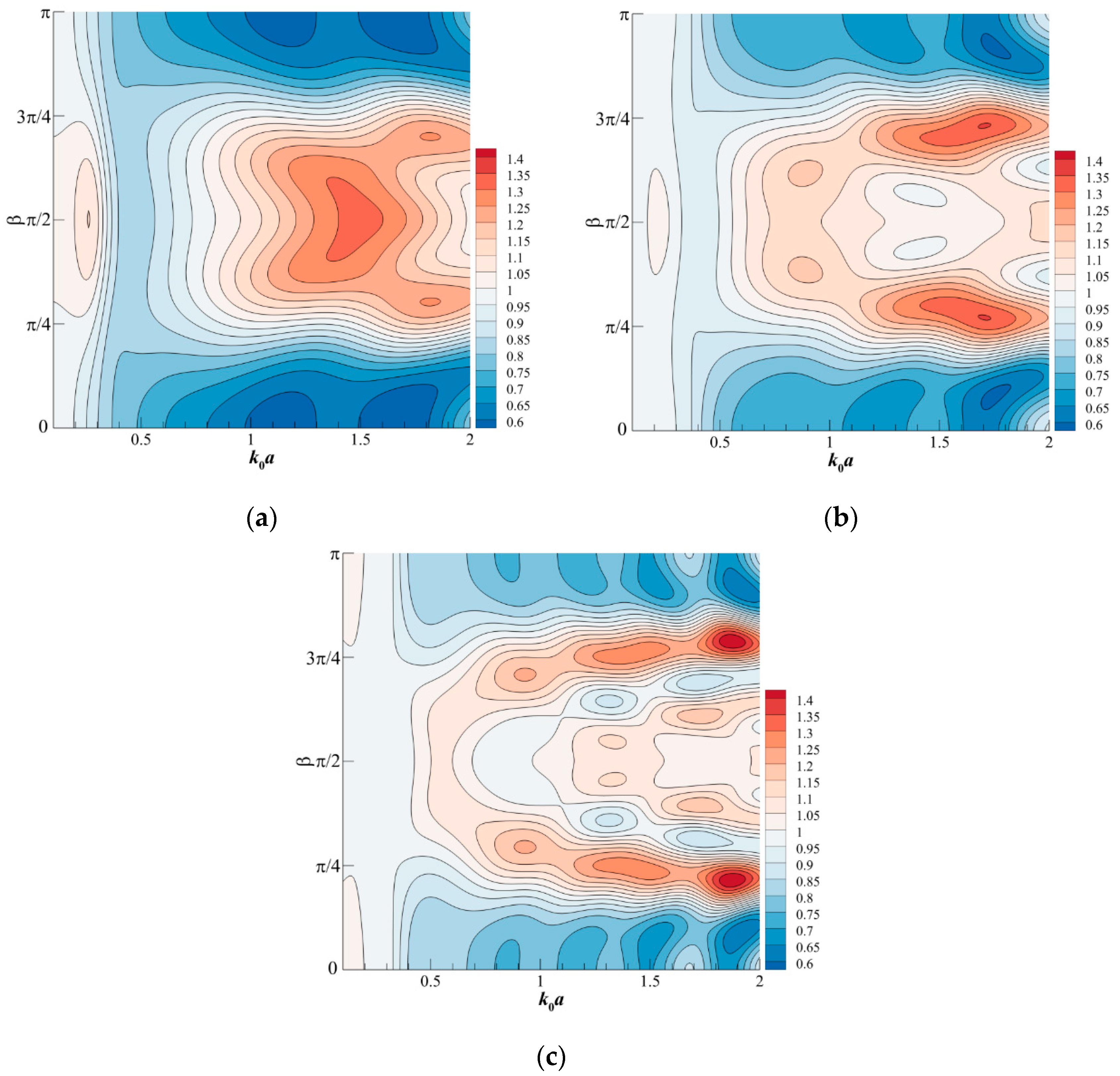
4.2. Two WECs
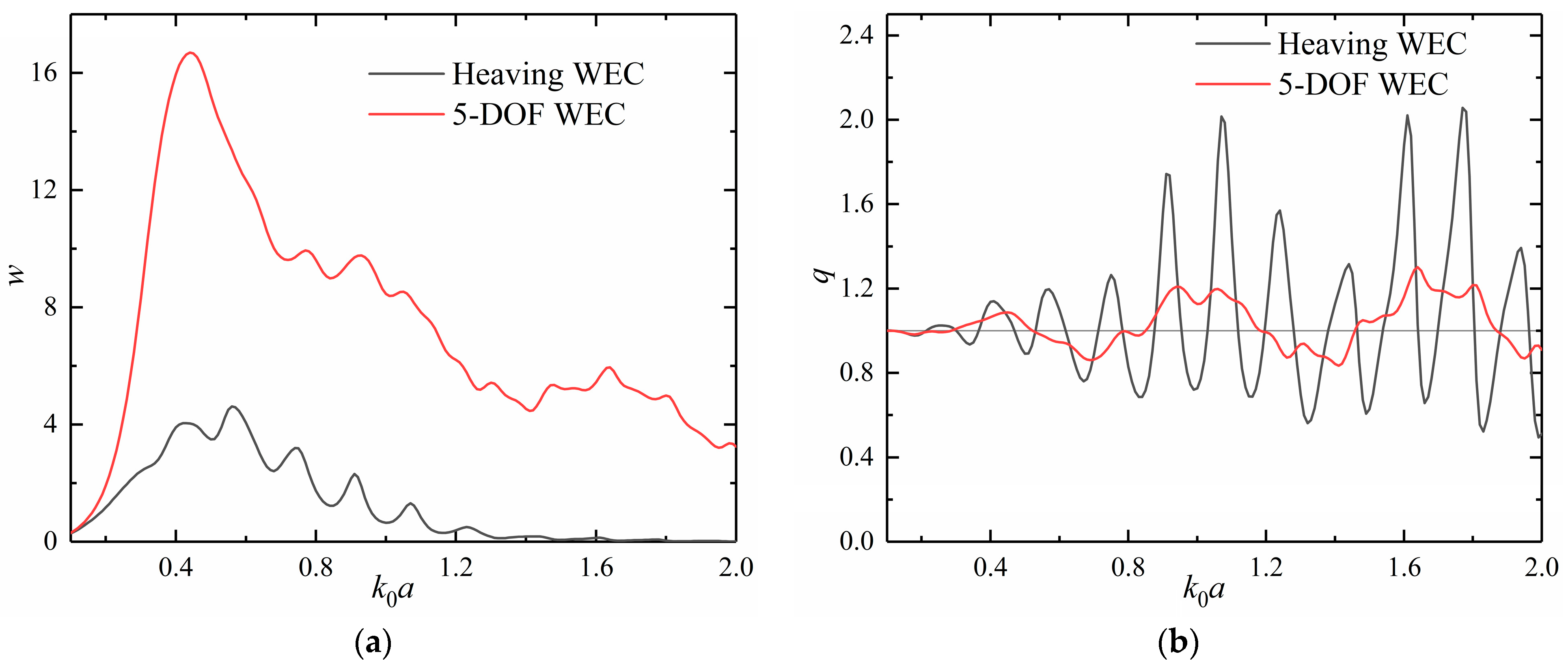
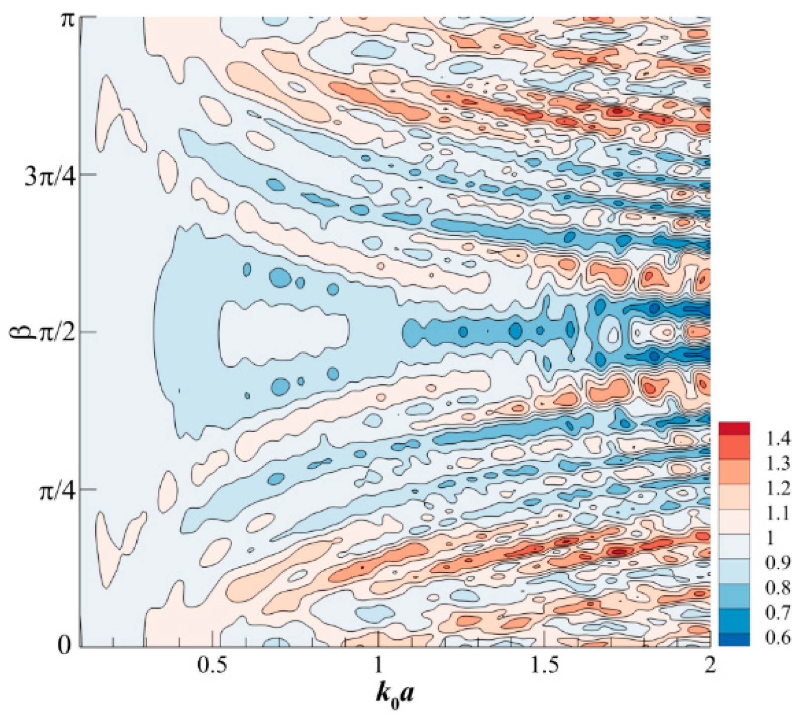
4.3. Five WECs
5. Conclusions
Author Contributions
Funding
Institutional Review Board Statement
Informed Consent Statement
Data Availability Statement
Conflicts of Interest
Appendix A
References
- Gunn, K.; Stock-Williams, C. Quantifying the global wave power resource. Renew. Energy 2012, 44, 296–304. [Google Scholar] [CrossRef]
- Antonio, F.D.O. Wave energy utilization: A review of the technologies. Renew. Sust. Energ. Rev. 2010, 14, 899–918. [Google Scholar]
- Göteman, M.; Giassi, M.; Engström, J.; Isberg, J. Advances and Challenges in Wave Energy Park Optimization—A Review. Front. Energy Res. 2020, 8, 26. [Google Scholar] [CrossRef] [Green Version]
- Tokić, G.; Yue, D.K.P. Hydrodynamics of periodic wave energy converter arrays. J. Fluid Mech. 2019, 862, 34–74. [Google Scholar] [CrossRef]
- WAMIT User Manual Version 7.0; User Manual; WAMIT, Inc.: Chestnut Hill, MA, USA, 2013.
- Babarit, A.; Delhommeau, G. Theoretical and numerical aspects of the open source BEM solver NEMOH. In Proceedings of the 11th EuropeanWave and Tidal Energy Conference, Nantes, France, 6–11 September 2015; pp. 1–12. [Google Scholar]
- Sinha, A.; Karmakar, D.; Soares, C.G. Performance of optimally tuned arrays of heaving point absorbers. Renew. Energy 2016, 92, 517–531. [Google Scholar] [CrossRef]
- De Andrés, A.D.; Guanche, R.; Meneses, L.; Vidal, C.; Losada, I.J. Factors that influence array layout on wave energy farms. Ocean Eng. 2014, 82, 32–41. [Google Scholar] [CrossRef]
- Zhong, Q.; Yeung, R.W. Wave-body interactions among energy absorbers in a wave farm. Appl. Energy. 2019, 233, 1051–1064. [Google Scholar] [CrossRef]
- Budal, K. Theory for absorption of wave power by a system of interacting bodies. J. Ship Res. 1977, 21, 248–253. [Google Scholar] [CrossRef]
- Evans, D.V. Some analytic results for two and three dimensional wave- energy absorbers. In Power from Sea Waves; Academic Press, Inc.: London, UK, 1980; pp. 213–249. [Google Scholar]
- Falnes, J. Radiation impedance matrix and optimum power absorption for interacting oscillators in surface waves. Appl. Ocean Res. 1980, 2, 75–80. [Google Scholar] [CrossRef]
- Simon, M.J. Multiple scattering in arrays of axisymmetric wave-energy devices. Part 1. A matrix method using a plane-wave approximation. J. Fluid Mech. 1982, 120, 1–25. [Google Scholar] [CrossRef]
- Williams, A.N.; Abul-Azm, A.G. Hydrodynamic interactions in floating cylinder arrays—II. Wave radiation. Ocean Eng. 1989, 16, 217–263. [Google Scholar] [CrossRef]
- Singh, J.; Babarit, A. A fast approach coupling Boundary Element Method and plane wave approximation for wave interaction analysis in sparse arrays of wave energy converters. Ocean Eng. 2014, 85, 12–20. [Google Scholar] [CrossRef] [Green Version]
- Kagemoto, H.; Yue, D.K.P. Interactions among multiple three-dimensional bodies in water waves: An exact algebraic method. J. Fluid Mech. 1986, 166, 189–209. [Google Scholar] [CrossRef]
- Ohkusu, M. Hydrodynamic forces on multiple cylinders in waves. In Proceedings of the International Symposium on the Dynamics of Marine Vehicles and Structures in Waves, London, UK, 1–5 April 1974; Institute of Mechanical Engineers: London, UK, 1974. [Google Scholar]
- Spring, B.H.; Monkmeyer, P.L. Interaction of plane waves with vertical cylinders. In Coastal Engineering, Proceedings of the 14th International Conference on Coastal Engineering Copenhagen, Denmark, 24–28 June 1974; ASCE: Reston, VA, USA, 1974. [Google Scholar]
- Yilmaz, O. Hydrodynamic interactions of waves with group of truncated vertical cylinders. J. Waterw. Port Coast. Ocean Eng. 1998, 124, 272–279. [Google Scholar] [CrossRef]
- Zeng, X.; Shi, M.; Huang, S. Hydrodynamic interactions of water waves with a group of independently oscillating truncated circular cylinders. Acta Mech. Sin. 2016, 32, 773–791. [Google Scholar] [CrossRef] [Green Version]
- Zeng, X.; Yu, F.; Shi, M.; Wang, Q. Fluctuation of magnitude of wave loads for a long array of bottom-mounted cylinders. J. Fluid Mech. 2019, 868, 244–285. [Google Scholar] [CrossRef] [Green Version]
- Flavià, F.F.; Meylan, M.H. An extension of general identities for 3D water-wave diffraction with application to the Diffraction Transfer Matrix. Appl. Ocean Res. 2019, 84, 279–290. [Google Scholar] [CrossRef]
- Garnaud, X.; Mei, C.C. Bragg scattering and wave-power extraction by an array of small buoys. Proc. R. Soc. A 2010, 466, 79–106. [Google Scholar] [CrossRef] [Green Version]
- Penalba, M.; Touzón, I.; Lopez-Mendia, J.; Nava, V. A numerical study on the hydrodynamic impact of device slenderness and array size in wave energy farms in realistic wave climates. Ocean Eng. 2017, 142, 224–232. [Google Scholar] [CrossRef] [Green Version]
- Thomas, S.; Giassi, M.; Göteman, M.; Hann, M.; Ransley, E.; Isberg, J.; Engström, J. Performance of a Direct-Driven Wave Energy Point Absorber with High Inertia Rotatory Power Take-off. Energies 2018, 11, 2332. [Google Scholar] [CrossRef] [Green Version]
- Wang, L.; Engström, J.; Leijon, M.; Isberg, J. Performance of arrays of direct-driven wave energy converters under optimal power take-off damping. AIP Adv. 2016, 6, 085313. [Google Scholar] [CrossRef] [Green Version]
- Babarit, A. On the park effect in arrays of oscillating wave energy converters. Renew. Energy 2013, 58, 68–78. [Google Scholar] [CrossRef] [Green Version]
- Babarit, A. Impact of long separating distances on the energy production of two interacting wave-energy converters. Ocean Eng. 2010, 37, 718–729. [Google Scholar] [CrossRef] [Green Version]
- Child, B.F.M.; Venugopal, V. Optimal configurations of wave energy device arrays. Ocean Eng. 2010, 37, 1402–1417. [Google Scholar] [CrossRef]
- Ruiz, P.M.; Nava, V.; Topper, M.B.R.; Minguela, P.R.; Ferri, F.; Kofoed, J.P. Layout optimization of wave energy converter arrays. Energies 2017, 10, 1262. [Google Scholar] [CrossRef] [Green Version]
- Sharp, C.; DuPont, B. Wave energy converter array optimization: A genetic algorithm approach and minimum separation distance study. Ocean Eng. 2018, 163, 148–156. [Google Scholar] [CrossRef]
- Fang, H.W.; Feng, Y.Z.; Li, G.P. Optimization of wave energy converter arrays by an improved differential evolution algorithm. Energies 2018, 11, 3522. [Google Scholar] [CrossRef] [Green Version]
- Giassi, M.; Göteman, M. Layout design of wave energy parks by a genetic algorithm. Ocean Eng. 2018, 154, 252–261. [Google Scholar] [CrossRef]
- Zhang, H.C.; Xu, D.L.; Liu, C.R.; Wu, Y.S. A floating platform with embedded wave energy harvesting arrays in regular and irregular seas. Energies 2017, 10, 1348. [Google Scholar] [CrossRef] [Green Version]
- Ning, D.Z.; Zhao, X.L.; Chen, L.F.; Zhao, M. Hydrodynamic performance of an array of wave energy converters integrated with a pontoon-type breakwater. Energies 2018, 11, 685. [Google Scholar] [CrossRef] [Green Version]
- McIver, P. Some hydrodynamic aspects of arrays of wave-energy devices. Appl. Ocean Res. 1994, 16, 61–69. [Google Scholar] [CrossRef]
- Kara, F. Time domain prediction of power absorption from ocean waves with wave energy converter arrays. Renew. Energy 2016, 92, 30–46. [Google Scholar] [CrossRef]
- Sarkar, D.; Doherty, K.; Dias, F. The modular concept of the oscillating wave surge converter. Renew. Energy 2016, 85, 484–497. [Google Scholar] [CrossRef]
- Giassi, M.; Thomas, S.; Shahroozi, Z.; Engström, J.; Isberg, J.; Tosdevin, T.; Hann, M.; Göteman, M. Preliminary results from a scaled test of arrays of point-absorbers with 6 DOF. In Proceedings of the 13th European Wave and Tidal Conference, Napoli, Italy, 1–6 September 2019. [Google Scholar]
- Falnes, J. Ocean Waves and Oscillating Systems: Linear Interactions Including Wave-Energy Extraction; Cambridge University Press: Cambridge, UK, 2002. [Google Scholar]
- Mavrakos, S.A.; Koumoutsakos, P. Hydrodynamic interaction among vertical axisymmetric bodies restrained in waves. Appl. Ocean Res. 1987, 9, 128–140. [Google Scholar] [CrossRef]
- McNatt, J.C.; Porter, A.; Chartrand, C.; Roberts, J. The performance of a spectral wave model at predicting wave farm impacts. Energies 2020, 13, 5728. [Google Scholar] [CrossRef]
- Garrett, C.J.R. Wave forces on a circular dock. J. Fluid Mech. 1971, 46, 129–139. [Google Scholar] [CrossRef]
- Yeung, R.W. Added mass and damping of a vertical cylinder in finite-depth waters. Appl. Ocean Res. 1981, 3, 119–133. [Google Scholar] [CrossRef]
- Sabuncu, T.; Calisal, S. Hydrodynamic coefficients for vertical circular cylinders at finite depth. Ocean Eng. 1981, 8, 25–63. [Google Scholar] [CrossRef]


| 5.51 | 0 | 0 | 2.50 | 2.94 | 3.19 |
Publisher’s Note: MDPI stays neutral with regard to jurisdictional claims in published maps and institutional affiliations. |
© 2022 by the authors. Licensee MDPI, Basel, Switzerland. This article is an open access article distributed under the terms and conditions of the Creative Commons Attribution (CC BY) license (https://creativecommons.org/licenses/by/4.0/).
Share and Cite
Zeng, X.; Wang, Q.; Kang, Y.; Yu, F. A Novel Type of Wave Energy Converter with Five Degrees of Freedom and Preliminary Investigations on Power-Generating Capacity. Energies 2022, 15, 3069. https://doi.org/10.3390/en15093069
Zeng X, Wang Q, Kang Y, Yu F. A Novel Type of Wave Energy Converter with Five Degrees of Freedom and Preliminary Investigations on Power-Generating Capacity. Energies. 2022; 15(9):3069. https://doi.org/10.3390/en15093069
Chicago/Turabian StyleZeng, Xiaohui, Qi Wang, Yuanshun Kang, and Fajun Yu. 2022. "A Novel Type of Wave Energy Converter with Five Degrees of Freedom and Preliminary Investigations on Power-Generating Capacity" Energies 15, no. 9: 3069. https://doi.org/10.3390/en15093069
APA StyleZeng, X., Wang, Q., Kang, Y., & Yu, F. (2022). A Novel Type of Wave Energy Converter with Five Degrees of Freedom and Preliminary Investigations on Power-Generating Capacity. Energies, 15(9), 3069. https://doi.org/10.3390/en15093069