Article

Design Method for Variable Frequency Brushless Synchronous Generators

1
Center for More-Electic-Aircraft Power Systems, Nanjing University of Aeronautics and Astronautics, Nanjing 211006, China
2
Department of Electronic Engineering, University of York, York YO10 5DD, UK
*
Author to whom correspondence should be addressed.
Energies 2022, 15(8), 2786; https://doi.org/10.3390/en15082786
Submission received: 5 March 2022 / Revised: 31 March 2022 / Accepted: 7 April 2022 / Published: 11 April 2022

Abstract

:
Brushless synchronous generators, which have the structure of three-stage generators to realize brushless excitation, are the most commonly used aero-generators. With the development of more electric aircraft technology, the output frequency of aero-generators is changing from constant to variable, and the characteristics of generators are also changed. To make sure that the generators can be adapted to the variable frequency operation, this paper analyzes the effects of different operating conditions on generator performance and proposes corresponding design methods. The design and verification of the electromagnetic field, fluid field, temperature field and stress field are carried out for the variable frequency generator. A prototype generator is manufactured according to the design results. An experimental platform is set up to test the performances of the designed generator. The final experimental results show that the generator can work well in variable frequency generation systems, which proves the design method proposed in this paper is effective and feasible.

1. Introduction

Since the beginning of the 21st century, more electric aircraft (MEA) technology has been widely applied, aiming to replace part of the aircraft’s secondary energy system with the electrical system, most of the onboard equipment are powered by electrical energy. MEA technology can effectively improve aircraft reliability and maintainability, reduce operating costs and the weight of the aircraft [1,2,3].
At present, civil airliners with MEA technology features mainly include Airbus’ A380, A350XWB and Boeing’s B787. The most important feature of these aircrafts is the replacement of the original Integrated Drive Generator (IDG) with a variable frequency generator (VFG). Table 1, below, shows the generator data of several wide-body aircraft. The generators before 2000 are in the range of 90 kVA to 120 kVA. The frequency of the output voltages is fixed to 400 Hz. The generators of MEAs are changed from IDG to VFG, the capacities are increased to the range of 100 kVA to 250 kVA. At the same time, the voltage level of the A350 and B787 are both doubled, thus the losses and weights of the cables can be reduced.
IDG is a kind of generator that integrates constant speed drive (CSD) and brushless synchronous generator (BSG). The constant speed operation of the generator is realized by CSD, which results in the output of alternating current with a constant 400 Hz frequency. Table 2 lists the weight data of several IDGs; it can be found that the weight of CSD generally accounts for about 60% to 70% of the total weight of IDG, which seriously restricts the power density of aero-generators.
In addition, the power density of the generator section is also affected by the need for a constant frequency. The rotor speed and pole pairs of the synchronous generator are constrained by the output voltage frequency, so increasing the rotor speed requires a corresponding decrease in the number of pole pairs. Therefore, in the 400 Hz constant generation system, the maximum generator speed is 24,000 rpm, which corresponds to 1 pole pair synchronous generator, so the increase in generator power density is limited [4].
The variable frequency generator eliminates the CSD and removes the frequency constraint, thus allowing for higher power density and greater generation capacity. However, compared to IDG, the operating frequency of VFG varies in the range of 360–800 Hz [6,7,8], the generator performance varies with the speed and frequency, which increases the difficulties of the generator design [9,10].
There are usually two methods to the design an aero-generator. The first method is to the optimization design based on the original generator [11]. In those cases, the electromagnetic load, current density and rotor stress can be easily selected based on the performance of the original generator. Another method is that when there is no original generator for reference, it is necessary to explore the verification of the working limit of the generator [12]. This means involving the calculation of multi-physical fields calculations, which includes electromagnetic field, fluid field, temperature field and stress field. While the working conditions of VSVF generator are far more than others, which leads to more calculations required in the design process. Therefore, for the design of VSCF generator, it is necessary to analyze the influence of different working conditions on its performance in advance, sort out the relationship and analyze and obtain the working conditions when various performances reach their limit values, so as to reduce the amount of relevant calculation and improve the design efficiency.
Literature [13,14,15,16] have studied the design method of aero-generator applied to high voltage direct current (HVDC) systems, but they only involve the design method of electromagnetic performance, lacks the content related to multi-physical fields. The authors of [17] proposed the electromagnetic, mechanical and thermal models of the aero-generator. These models are based on the analytical formula and are relatively simple. They are used to evaluate the impact of key dimensional parameters such as the length diameter ratio on the overall performance of the generator. The three-dimensional lumped parameter thermal network model of generator is proposed in literature [18], which lays a foundation for the multi-physical field design of aero-generators. Referring to the generator applied in B787, the authors of [9] designed a generator with the same index, and simulated and verified the electromagnetic field, stress field, temperature field and other physical fields. The results show that the designed prototype can further improve the power density by replacing air cooling method with liquid cooling method.
It can be seen from the above literature that with the development of MEA technology, the design requirements of brushless synchronous generator are gradually improving, and the research on its multi-physical field design method is paid attention to by researchers.
In this paper, the influence of different operating conditions on the performance of BSGs is analyzed. The design method is proposed based on the previous analysis. The design and verification are implemented based on the electromagnetic field, fluid field, temperature field and stress field analysis. A prototype generator is manufactured and tested in an experimental platform. The performances of the designed generator operating at variable frequency are demonstrated in the last section.

2. Influence of the Operating Conditions

BSG consists of three stages: main generator (MG), exciter and permanent magnet generator (PMG) [8,19]. It is the most commonly used aero-generator because the brushless excitation is achieved by the application of the exciter, which improves the service life of the synchronous generators. The complete BSG system structure is shown in Figure 1.
The design requirements of BSGs are mainly divided into three kinds: electromagnetic performance, mechanical performance and cooling performance: the electromagnetic performance requirements include rated voltage, rated power, rated frequency, power factor, efficiency, overload capacity and power quality; the mechanical performance requirements include generator weight, volume size, rated speed, maximum over-speed and static suspension moment; the cooling performance requirements include the cooling method and cooling medium. For example, the performance requirements of an emergency generator used for Ram Air Turbine (RAT) are shown in Table 3, where the items 1–7 are electromagnetic performance requirements, items 8–12 are mechanical performance requirements and the item 13nis the cooling performance requirements.
The power quality requirements of generators include voltage accuracy, crest factor, voltage modulation amplitude, voltage phase difference, distortion factor, harmonic content and distortion spectrum. These indicators are usually determined by the electromagnetic design of the MG.
The impact of different operating conditions on generator performance varies. The influences of flight altitude, temperature, rotor speed and load conditions, on the generator performance, are as follows.
(1) Flight altitude
The flight altitude of military helicopters is generally 3000 to 6000 m, civil airliners are generally 10,000 to 13,000 m, and the fighters are 18,000 to 20,000 m. Accordingly, the onboard equipment needs to adapt to the change in flight altitude. When the altitude rises from 0 to 20,000 m, the atmospheric pressure decreases by 94.6%, the air temperature decreases by 71.5 °C, the air density and the specific heat capacity of air volume decrease by 92.8%. The flight altitude is higher, the air becomes thinner. Although the friction loss of the generator will be significantly reduced at this time, the cooling capacity of the air-cooled system decreases sharply.
(2) Temperature
According to DO-160G, aero-generators need to adapt to the ambient temperature of −55 to 70 °C. Different ambient temperatures affect the physical properties of electromagnetic materials and cooling media. At the same time, the losses generated by the generator in the process of power generation will also be converted into heat, affecting the temperature of the motor components.
To increase the power density of the generator, the winding of the generator is usually selected as C-class insulation material, which can withstand temperatures of 200 to 240 °C. Therefore, the temperature of the generator winding will vary between −60 and 180 °C. When the temperature of the winding becomes higher, the changes in the generator performances are as follows:
(a)
The armature winding temperature rise leads to an increase in voltage drop, resulting in more excitation power requirements.
(b)
The winding temperature rise leads to higher winding resistance, increased copper losses and lower efficiency.
(c)
The resistance of dumping windings becomes larger, the negative sequence impedance increases and the generator performances under unbalanced loads become poorer.
(d)
The rotating rectifier operating mode is affected by the winding temperature.
(e)
The performance of permanent magnets in PMG decreases and the risk of demagnetization is greater.
(3) Rotor speed
Compared with IDG, VFG needs to meet the performance requirements at different rotor speeds, which will affect the magnetic saturation characteristics of the generator and change the reactance, thus affecting the generator performance. The specific impact includes the following aspects:
(a)
The speed is higher, the core saturation is less and less excitation power is required.
(b)
The skin effect and proximity effect of the generator windings will be more obvious with the increase in frequency, so the AC loss is greater.
(c)
Eddy current losses in the damping windings of the main generator and the permanent magnets of the PM machine become larger as the frequency increases.
(d)
High speed corresponds to high frequency, the reactance of the generator becomes larger, the armature reaction is enhanced.
(e)
Variations in the MG excitation current and the armature reactance of the exciter also affect the rectifier operating mode of the rotation rectifier.
(f)
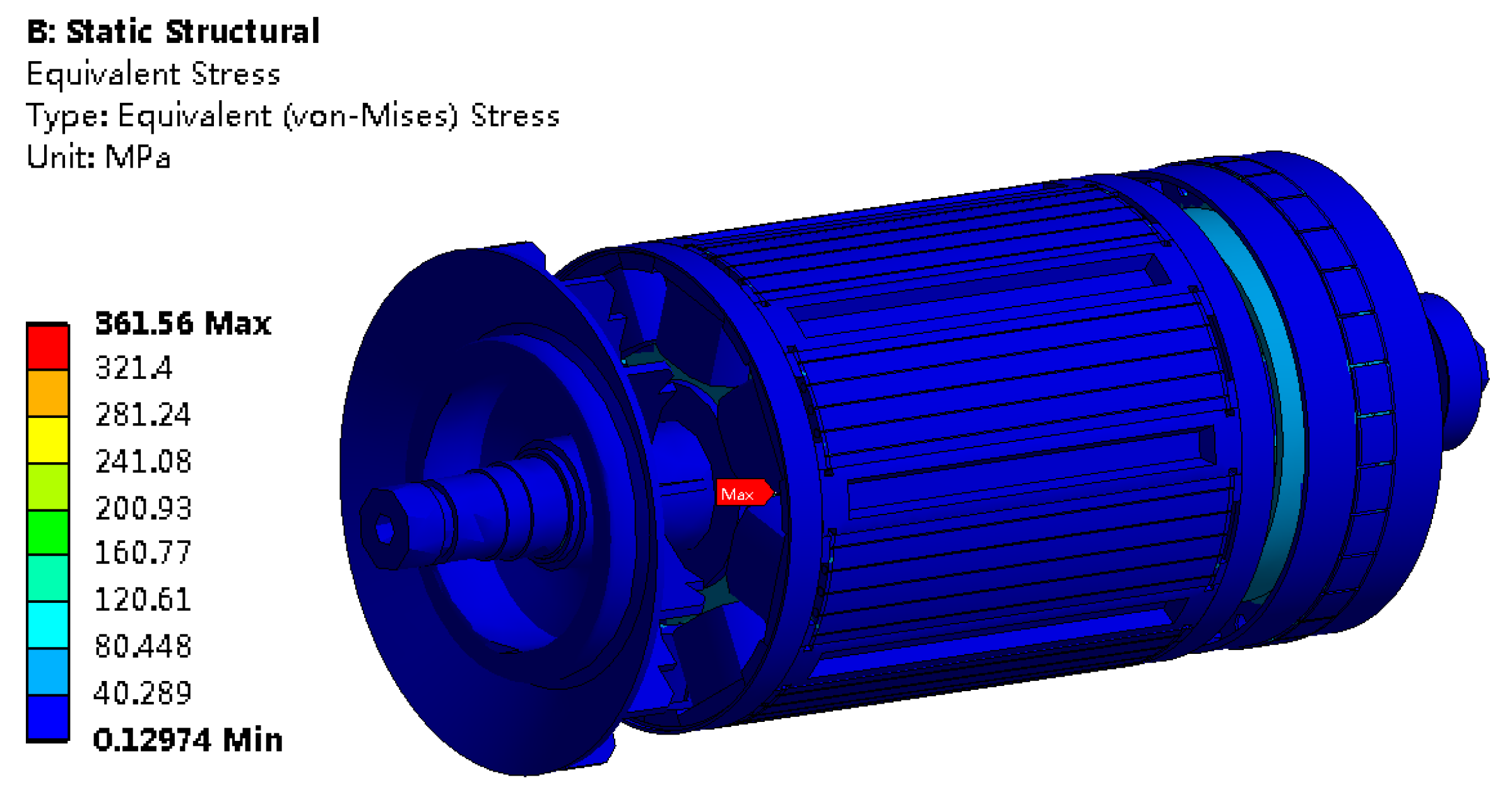
The stress of the generator rotor will be greater under the higher speed, which will increase the risk of structural damage to the generator rotor.
(4) Load conditions
Aero-generators need to work under different load conditions. Not only the output power but also the power factor changes. At the same output power, the armature reaction of the MG under inductive load will be greater compared to the resistive load, so the generator needs more excitation power when the power factor becomes smaller.
In addition, generators need to have a certain overload capacity and short-circuit capability, these variable load conditions can also have impact on the electromagnetic performances.
A comprehensive analysis of the impact of the above operating conditions on the performance of generators can be summarized as the following operating conditions that need to be considered in the design process of generators.
(a)
The power capability of the generator needs to be checked at high temperature and low-speed conditions.
(b)
The magnetic circuit saturation of the generator needs to be checked under high temperature, low speed and inductive overload conditions.
(c)
The power quality of the generator needs to be checked under high temperature and high-speed conditions, the load conditions depend on the specific situation.
(d)
The electromagnetic losses of the generator reach their maximum values at high temperature, low speed and inductive overload conditions.
(e)
The winding temperature rise of the generator needs to be checked at high flight altitude, high temperature, low speed and inductive overload conditions.
(f)
The structural strength of the generator rotor needs to be checked under high temperature and high-speed conditions.
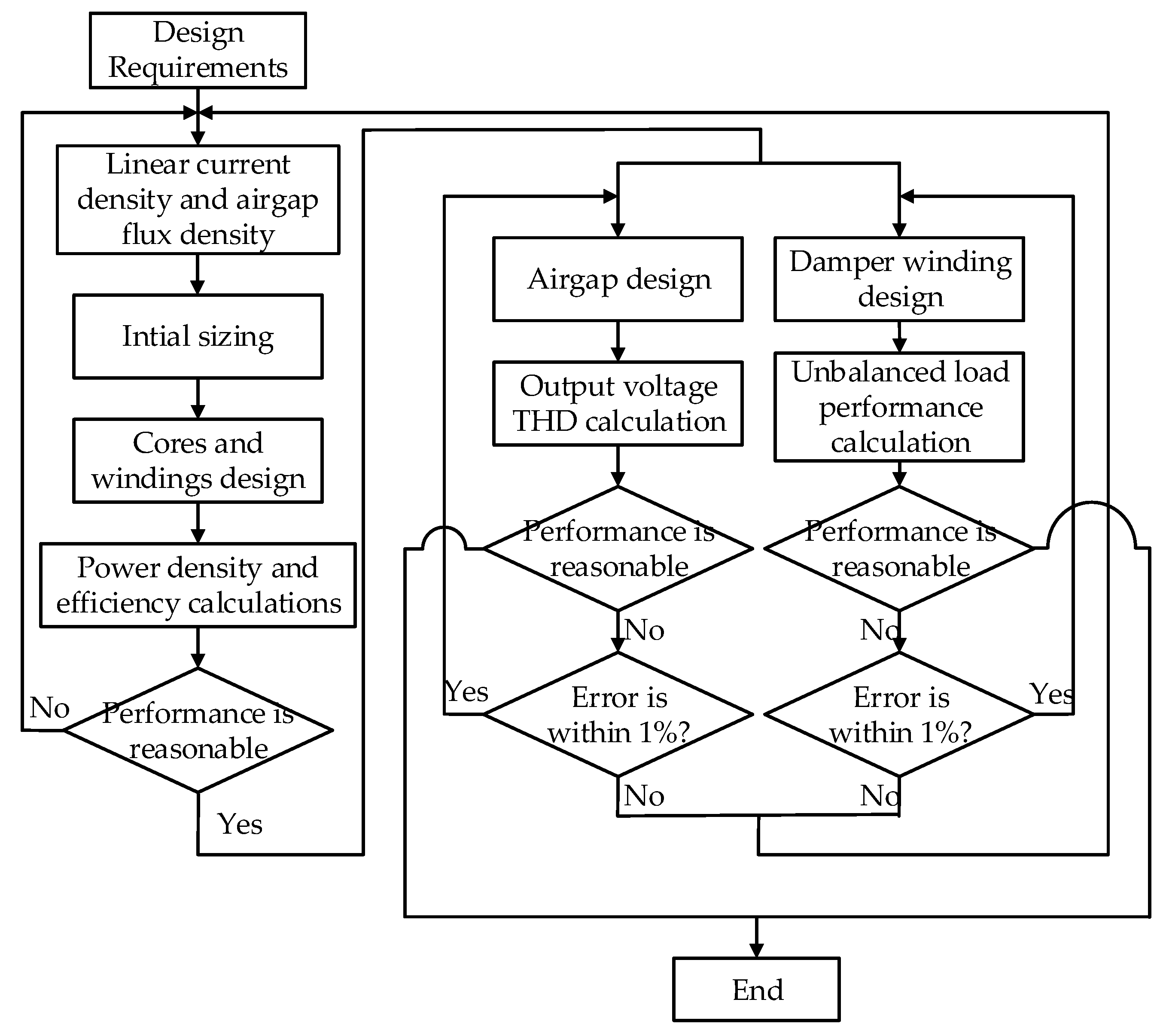
3. Design Method

Based on the previous analysis, the generator has variable operating conditions and performance requirements, which requires the designers to adopt a multi-physics field design approach in the design process [20]. The complete design process of a generator consists of three parts: electromagnetic design, cooling design and structural design.
The design of exciter and PMG depend on the excitation power of MG and exciter respectively, so it is necessary to design the MG first, then the exciter and finally the PMG, the design process is shown in Figure 2.

3.1. Electromagnetic Design
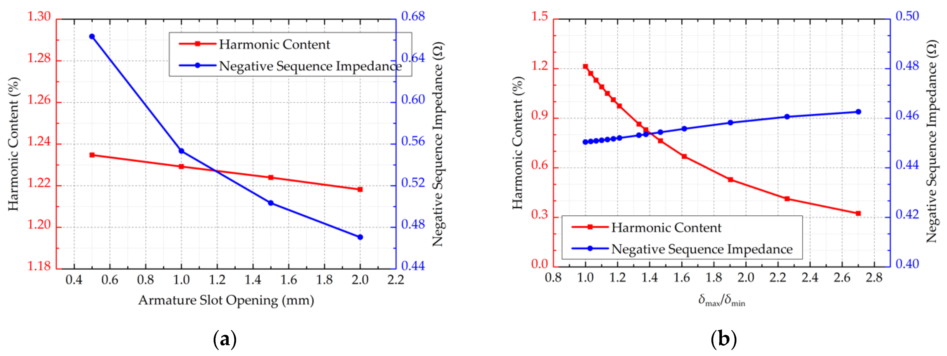
The effective material weight of the MG usually accounts for 50% to 70% of the total weight of the BSG. Take a JF-10D generator as an example, the total weight of the generator is 8.5 kg and the effective material weight of the stator/rotor of the main generator is 2.78 kg and 1.47 kg respectively, the effective material weight of the MG is exactly 50% of the total weight of the generator, as shown in Figure 3. Therefore, the effective material weight of the MG can be set as 50% of the total weight of the generator during the design process.
The conventional electromagnetic design process of the MG is shown in Figure 4. The related formula calculation can be found in the literature [21].
For variable frequency BSGs, the power quality requirements are more difficult to meet under high-speed conditions, so extra attention is needed in the electromagnetic design process. The most important power quality requirements are the harmonic content of the output voltage and the voltage unbalance and phase shift under the unbalanced load, the latter determined by the MG’s negative sequence impedance [22]. There are three main influencing factors, which are analyzed in detail as follows.
(1) Air gap
The air gap shape parameters mainly include armature slot opening Bs0, air gap length δ and pole arc coefficient αp, their effects on generator voltage harmonic content and negative sequence impedance are shown in Figure 5. According to the data in the figure, it is known that:
(a)
When the Bs0 becomes greater, the negative sequence impedance decreases sharply and the harmonic content decreases slightly.
(b)
The more uneven the air gap is, the smaller the harmonic content is.
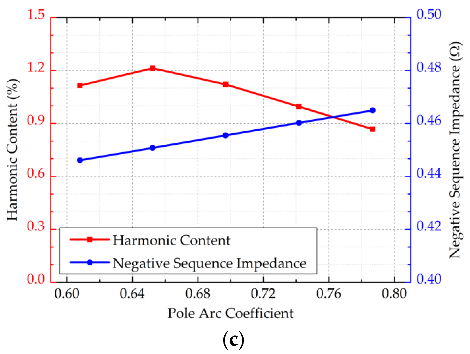
(c)
αp has a limited influence on the negative sequence impedance, but its effect on the harmonic content is significant, as αp gradually increases, the harmonic content first increases and then decreases.
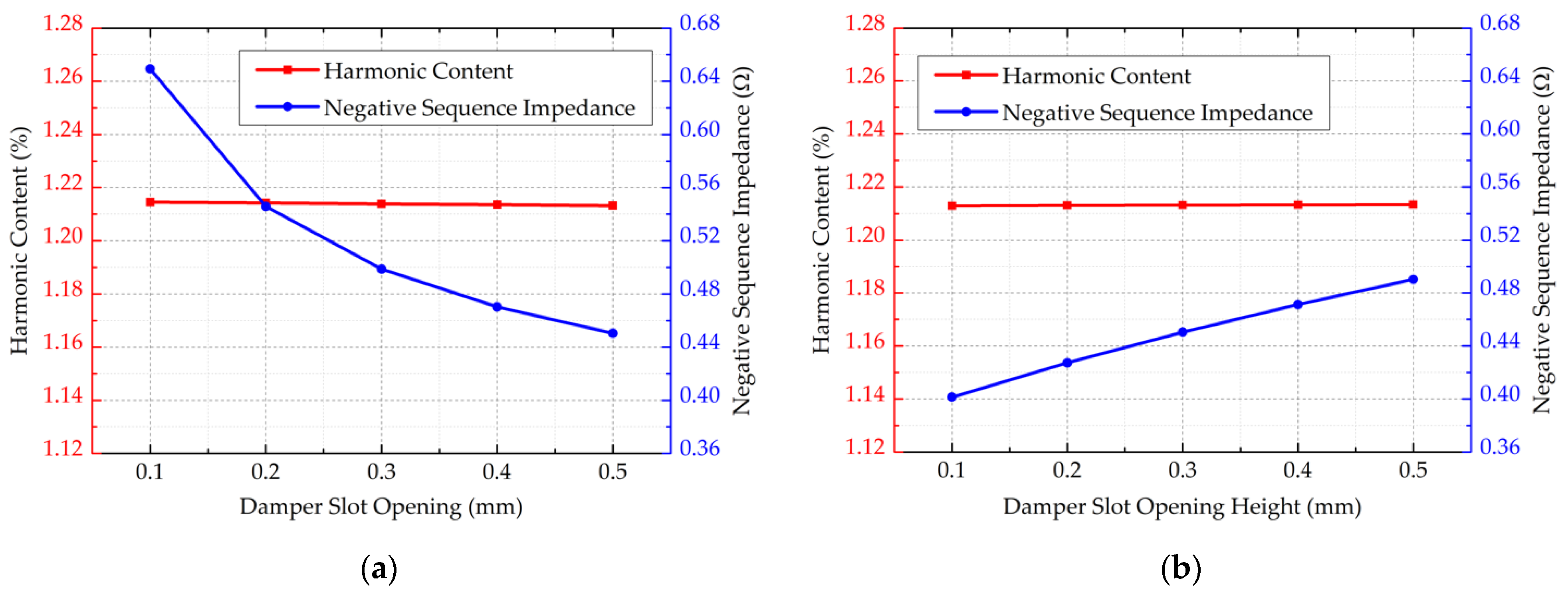
(2) Damping winding
The damping winding parameters mainly include damper slot opening Bd0, damper slot opening height Hd0, damper diameter Dd and damper slot pitch SP, their effects on generator voltage harmonic content and negative sequence impedance are shown in Figure 6. According to the data in the figure, it can be seen that:
(a)
The parameters related to the damping winding have an almost slight effect on the harmonic content and are mainly used to reduce the negative sequence impedance.
(b)
The negative sequence impedance decreases significantly with the increase of Bd0.
(c)
Hd0 has a greater effect on the negative sequence impedance.
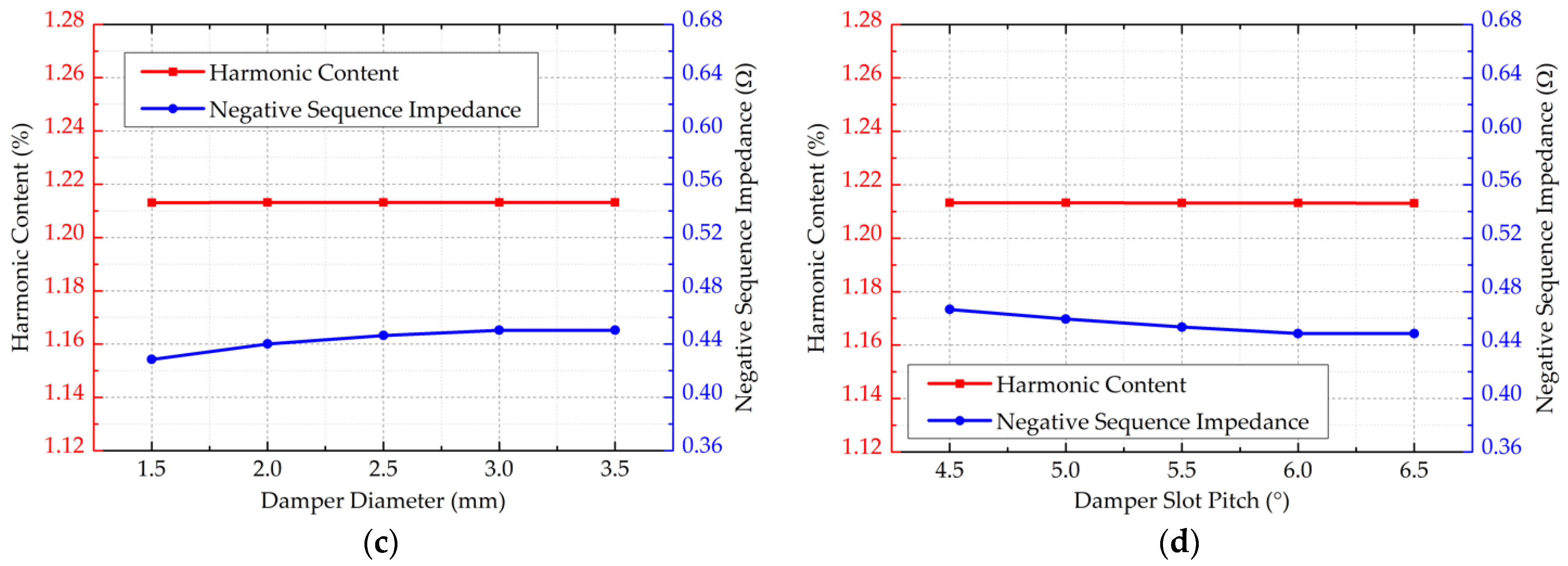
(d)
The influence of Dd on the negative sequence impedance is small. When Db increases, although the negative sequence resistance decreases, the leakage reactance of the damping winding increases, which leads to a larger negative sequence impedance.
(e)
The effect of SP on the negative sequence impedance is small.
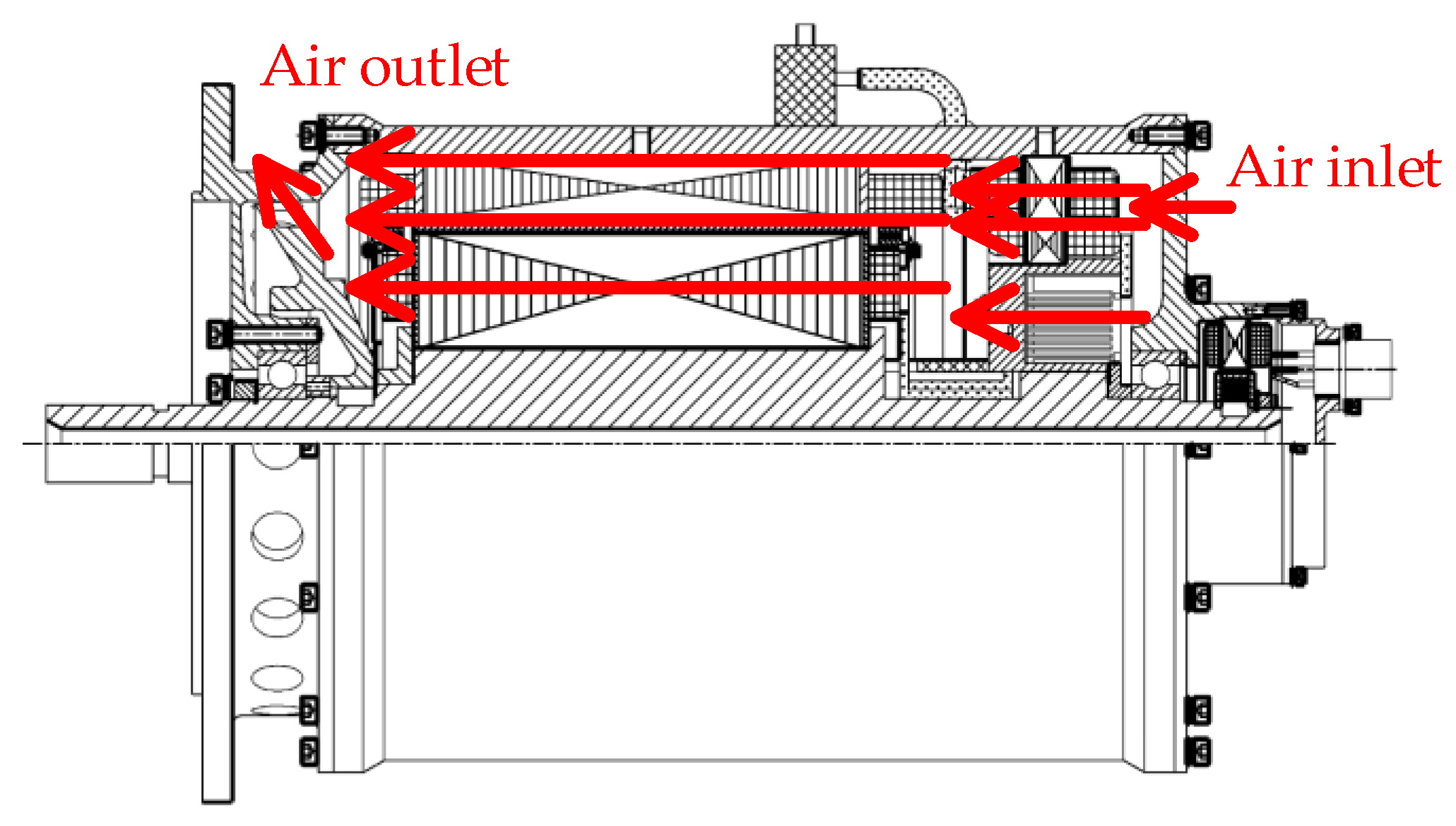
(3) The turns of armature winding
Figure 7 shows the effect of turns-in-series per phase of the armature winding Ns on the harmonic content and negative sequence impedance, while the airgap flux density keeps constant. It can be found that Ns have a significant effect on both performances, and both become significantly larger as Ns increase.
According to the previous analysis, in the electromagnetic design process of the MG, it is necessary to adjust the air gap shape according to the voltage harmonic content and to adjust the damping winding parameters according to the negative sequence impedance. If the two adjustments cannot meet the requirements, it is necessary to reduce the turns-in-series per phase, which means reducing the power density of the MG in exchange for the improvement of power quality.
According to the above analysis, in the VSVF systems, in order to design the main generator more reasonably, the design process should be divided into two parts, including the design of main dimensional parameters and the design of waveform performance. The proposed design method is shown in Figure 8.
After the design of the MG is completed, its excitation data can be calculated by the Finite Element Method (FEM) simulation software, the optimization design of the exciter can be started. The exciter is a rotating-armature synchronous generator, whose electromagnetic design process is similar to that of the MG, but the performance requirements are completely different. In order to achieve the linear current amplifier characteristics of the generator, the exciter needs to reduce its air gap length, increase the number of winding turns and reserve sufficient margin for current overshoot during transients.
The PMG is also a synchronous generator, but the excitation winding is replaced with permanent magnets, so the design approach will be somewhat different. Due to the characteristics of permanent magnets, the PMG cannot be demagnetized in a short circuit fault, so their armature windings should be designed to high impedance to reduce the short circuit currents.
The parameters of the BSG obtained from the final design are shown in Table 4. Since this BSG is a technology verification prototype, the generator cores use silicon steel instead of iron–cobalt–vanadium alloy.

3.2. Cooling Design

According to the parameters of the designed generator, the loss data are obtained by the FEM simulation [23,24] as shown in Table 5, the generator is operating under 180 °C winding temperature, 6795 rpm, two times overload, 0.75 power factor. Based on these loss data, the design of the cooling system can be carried out.
The BSG is axially ventilated and cooled, its internal air path is set up as shown in Figure 9, the red arrows indicate the direction of cooling air flow. The cooling airflow enters the BSG from the non-drive end cap, passes through the exciter and the rotating rectifier first, and then passes through the MG, and finally is pumped outside the drive end cap by the fan. The air paths of the exciter as well as the MG are 3-way parallel structure, passing through the stator, the air gap and the rotor, respectively. The fan is used for the ground testing.
In order to calculate the total ventilation resistance of the cooling circuit, it is necessary to simplify the flow-network structure and perform s eries/parallel equivalent calculations to obtain the total value. The calculation formula of ventilation resistance is [25]:
Z n = α n γ 2 g 1 S n 2
where αn is the friction coefficient, γ is the specific gravity of air, g is the gravity acceleration, Sn is the cross-sectional area of the air path.
The value of the friction coefficient αn is determined by the path structure. The air specific gravity γ can be calculated by the following equation:
γ = 0.0035 P H 273 + T H
where PH is the air pressure at a specific altitude and TH is the air temperature at a specific altitude.
It is known that the BSG’s working altitude is from 0 m to 13,000 m, and the ambient temperature is from −55 °C to 70 °C, so the air resistance of the generator can be obtained as shown in the Table 6
The ventilation resistance characteristic curve of the BSG can be calculated from the above table, as shown in Figure 10.
The active pressure generated by the airflow during forced ventilation is
H = γ 2 g v 2
where v is the flight speed. This equation shows that the forced-air cooling system provides a fixed source of air pressure, which is related to the flight altitude, the ambient temperature and the flight speed.
Take B787 as an example, the lowest equivalent airspeed of its RAT at 13,000 m altitude is 180 KEAS, which is about 92.5 m/s; the lowest equivalent airspeed at sea level is 120 KEAS, which is about 62 m/s, so the air pressure data of forced-air cooling system can be obtained as shown in Table 7.
According to the ventilation resistance and ventilation pressure, the flow rate can be calculated under different working conditions as shown in Table 8. From the table, it can be seen that the air flow generated by forced ventilation is not affected by the ambient temperature because the pressure and resistance are both proportional to γ, while the flow rate is exactly equal to the square root of pressure divided by resistance, so it is not affected by γ.
Based on the previous analysis, the airflow at sea level is the smallest, meanwhile the specific heat capacity of air is large and the heat dissipation ability of the airflow is better. Therefore, the winding temperature needs to be checked under high temperature conditions at high flight altitude.
The cooling flow rate obtained from Table 8 was input into MotorCAD software to calculate the winding temperature of the generator, and the results were obtained in Figure 11. The maximum temperature of the armature winding is 142.6 °C and the value of the excitation winding is 165.8 °C, both are under the pre-taken value of 180 °C and meet the operation requirements of the C-Class winding.

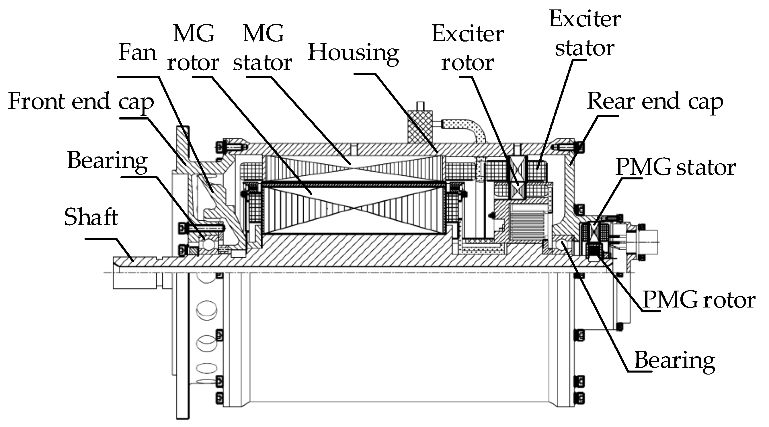
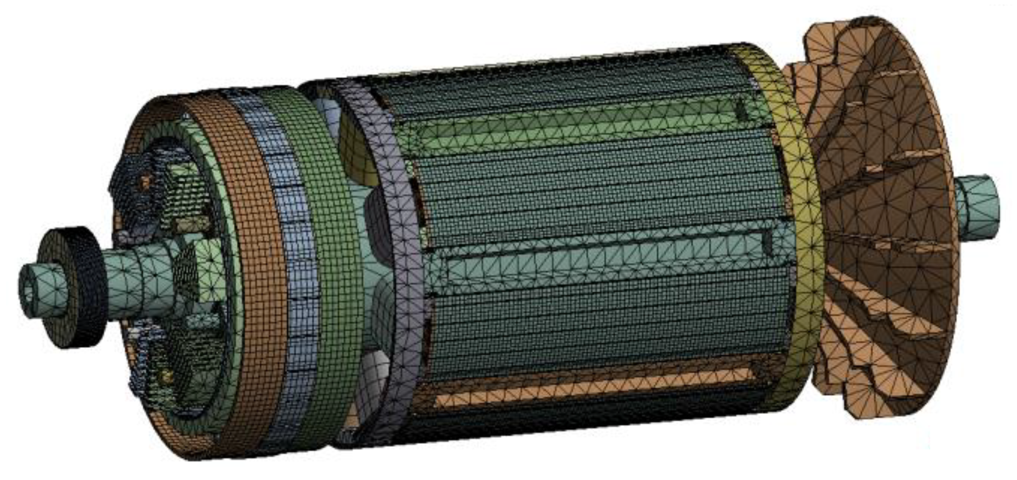
3.3. Structural Design
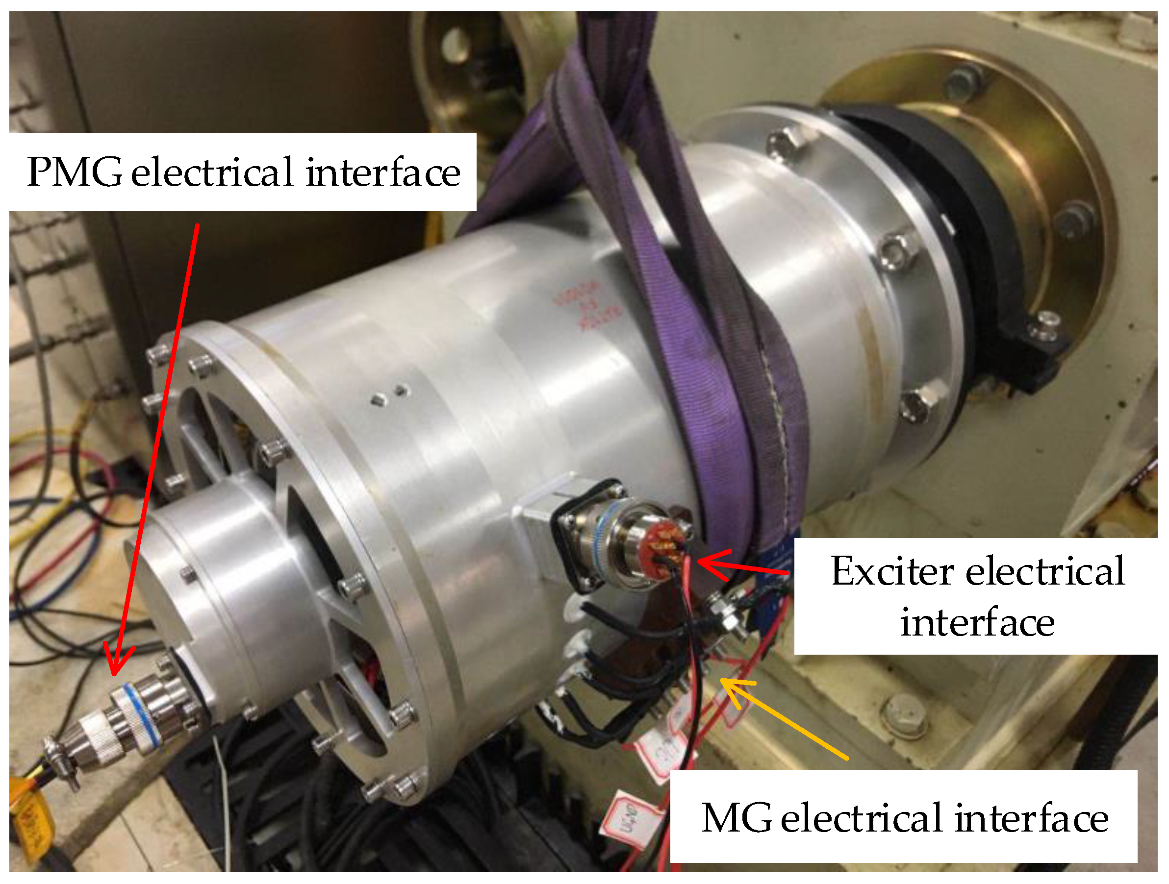
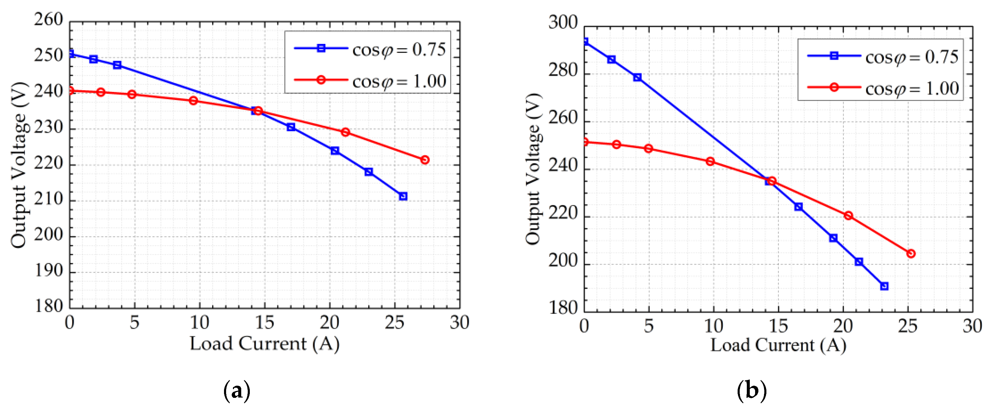
The structure of the BSG is shown in Figure 12, including the PMG stator/rotor assembly, exciter stator/rotor assembly, MG stator/rotor assembly, housing, front/rear end caps, bearings and drive shaft.
The rotor of a generator consists of four main parts: fan, MG rotor, exciter rotor and PMG rotor, as shown in Figure 13. The MG rotor includes the rotor core, excitation winding, damping winding, slot wedge and hoop ring, the exciter rotor includes the rotor core, armature winding, bracket, shield, rotating rectifier and heat sink and the PMG rotor includes the rotor core, permanent magnet and shield.
Variety of materials are used for the generator rotor, corresponding to different components, and their physical properties are shown in Table 9.
The rotor of the BSG has a complex structure and many materials, its stress cannot be simply calculated by the formula, but needs to be checked with the help of FEM simulation.
After inputting the rotor structure model and the corresponding material data into the simulation software, the obtained generator rotor mesh dissection model is shown in Figure 14.
The rotor speed is set to 10,000 rpm, the equivalent stress distribution of the BSG rotor is obtained in Figure 15. The result shows that, the maximum value of the rotor stress is 361.56 MPa, which is located at the main generator rotor hoop ring.
After the above simulation verification, the stresses on the generator rotor are less than the yield strength of the relevant materials, so the rotor structure meets the mechanical requirements.

4. Experiments

A variable frequency BSG is developed based on the previous design results, as shown in the Figure 16. The generator contains three electrical interfaces: the MG electrical interface, the exciter electrical interface and the PMG electrical interface, which correspond to the stator windings of each stage of the generator, and the exciter electrical interface is responsible for the outputs of J-type thermocouples buried inside the generator.
The architecture of the power generation system test platform is shown in the Figure 17, where MG_A, MG_B, MG_C and MG_N are the load voltage sampling signals, IF_+ and IF_− are the excitation windings of the exciter, TEMP1, TEMP2 and TEMP3 are the voltage signals of J-type thermocouples, PMG_A, PMG_B and PMG_C are the three phase armature windings of the PMG. The upper computer and the Generator Control Unit (GCU) are placed in an isolated room behind the wall to ensure the safety of the experimental personnel during the experimental operation. The generator is connected to the test-bed through an adapter plate and a shift sleeve, the output shaft speed of the test-bed can be controlled by the upper computer to drive the generator. The electrical interface of the MG is connected to the load bank, the voltage sampling line is connected to the GCU at the end of the load bank, and the electrical interfaces of the exciter and PMG are also connected to the GCU to realize the closed-loop control of the load voltages.
Due to the short cable during the experimental test, the effect of its voltage drop can be almost ignored, so the rated output voltage of the generator is set to 235 V instead of 230 V in the experiment. The no-load characteristic of the generator at 6795 rpm is shown in Figure 18. Figure 18 shows that the results between experiment and FEM simulation are very close, so the FEM simulation applied in Section 3 is reliable. The saturation coefficient of the generator can be calculated from the no-load characteristic data, and the result is 1.03.
The external characteristics of the generator mean the variation of generator output voltage with load current at a certain speed, a certain excitation current and a certain power factor. The external characteristics curves of the BSG obtained from the experiment are shown in Figure 19. According to the data in the figure, the voltage regulation rate of the generator connected to inductive load and resistive load are 6.8% and 2.4%, respectively, at 6795 rpm; when the speed is increased to 9615 rpm, the voltage regulation rates under these two load conditions rise to 24.9% and 7.0%, respectively. This shows that the external characteristics of the BSG are softer at higher frequency.
The steady-state test data of the generator are shown in Table 10. These data show that the generator can operate normally from 6795 rpm to 9615 rpm, no load to overload and inductive load to resistive load.
The harmonic data of the generator at different speeds and load conditions are shown in Table 11. Since the MG armature winding adopts 120° phase belt with 5/6 short pitch, which weakens the 3rd and 5th harmonic. As a result, the 7th harmonic is the highest content among all harmonics. MIL-STD-704F requires that the single harmonic content of the output voltage should not exceed 1.5% and the total harmonic content should not exceed 3.0%. From the data in Table 11, it can be seen that this designed BSG meets the requirement under full working condition.

5. Conclusions

This paper analyzes the performance requirements and operating conditions of the variable frequency BSGs, summarizes the influence of different operating conditions on the generator performances.
Based on the system characteristics and operating conditions, this paper proposes a corresponding design method that uses a multi-physical field design process including electromagnetic, fluid, temperature and stress fields.
In the electromagnetic design, this paper studies and analyzes the effects of generator air gap shape, damped winding structure and armature winding turns on generator harmonic content and negative sequence impedance, provides a reference basis for the optimal design of its power quality.
This paper analyzes the design of cooling duct characteristics such as air resistance and flow rate for the generator under forced-air cooling conditions, and calculates the MG winding temperature by temperature FEM simulation.
The overall structure of the generator is designed and the rotor stress is calculated to verify that the structural strength is enough to cope with the overspeed in the design requirements.
Finally, based on the previous analysis and design results, a prototype generator is manufactured and tested. The results show that the design method proposed in this paper can meet the requirements of the BSG under variable frequency operating conditions.

Author Contributions

Conceptualization, X.Z.; Data curation, Y.W. and Q.W.; Methodology, Y.W.; Project administration, H.W.; Software, W.L.; Writing original draft, Y.W. All authors have read and agreed to the published version of the manuscript.

Funding

This research was funded by the Funding of Jiangsu Innovation Program for Graduate Education, grant number KYCX17_0263.

Institutional Review Board Statement

Not applicable.

Informed Consent Statement

Not applicable.

Data Availability Statement

Not applicable.

Conflicts of Interest

The authors declare no conflict of interest.

References

  1. Wheeler, P.; Bozhko, S. The More Electric Aircraft: Technology and challenges. IEEE Electrif. Mag. 2014, 2, 6–12. [Google Scholar] [CrossRef]
  2. Sarlioglu, B.; Morris, C.T. More Electric Aircraft: Review, Challenges, and Opportunities for Commercial Transport Aircraft. IEEE Trans. Transp. Electrif. 2015, 1, 54–64. [Google Scholar] [CrossRef]
  3. Tom, L.; Khowja, M.; Vakil, G.; Gerada, C. Commercial Aircraft Electrification—Current State and Future Scope. Energies 2021, 14, 8381. [Google Scholar] [CrossRef]
  4. Madonna, V.; Giangrande, P.; Galea, M. Electrical Power Generation in Aircraft: Review, Challenges, and Opportunities. IEEE Trans. Transp. Electrif. 2018, 4, 646–659. [Google Scholar] [CrossRef]
  5. Burns, J.V. Constant Speed Generating Systems; SAE Technical Paper 771001; SAE: Warrendale, PA, USA, 1977. [Google Scholar] [CrossRef]
  6. Barzkar, A.; Ghassemi, M. Electric Power Systems in More and All Electric Aircraft: A Review. IEEE Access 2020, 8, 169314–169332. [Google Scholar] [CrossRef]
  7. Nøland, J.K.; Leandro, M.; Suul, J.A.; Molinas, M. High-Power Machines and Starter-Generator Topologies for More Electric Aircraft: A Technology Outlook. IEEE Access 2020, 8, 130104–130123. [Google Scholar] [CrossRef]
  8. Wang, Y.; Nuzzo, S.; Zhang, H.; Zhao, W.; Gerada, C.; Galea, M. Challenges and Opportunities for Wound Field Synchronous Generators in Future More Electric Aircraft. IEEE Trans. Transp. Electrif. 2020, 6, 1466–1477. [Google Scholar] [CrossRef]
  9. Pasquinelli, M.G.; Bolognesi, P.; Guiducci, A.; Nuzzo, S.; Galea, M. Design of a High-Speed Wound-Field Synchronous Generator for the More Electric Aircraft. In Proceedings of the 2021 IEEE Workshop on Electrical Machines Design, Control and Diagnosis (WEMDCD), Modena, Italy, 8–9 April 2021; pp. 64–69. [Google Scholar]
  10. Wang, Y.; Wang, H.; Liu, W.; Wang, Q. A Novel Fuzzy PI Control Method for Variable Frequency Brushless Synchronous Generators. Energies 2021, 14, 7950. [Google Scholar] [CrossRef]
  11. Zhao, X.; Wang, S.; Niu, S.; Fu, W.; Zhang, X. A Novel High-Order-Harmonic Winding Design Method for Vernier Reluctance Machine With DC Coils across Two Stator Teeth. IEEE Trans. Ind. Electron. 2022, 69, 7696–7707. [Google Scholar] [CrossRef]
  12. Zhao, X.; Niu, S.; Zhang, X.; Fu, W. Flux-Modulated Relieving-DC-Saturation Hybrid Reluctance Machine With Synthetic Slot-PM Excitation for Electric Vehicle In-Wheel Propulsion. IEEE Trans. Ind. Electron. 2021, 68, 6075–6086. [Google Scholar] [CrossRef]
  13. Camarano, T.; Wu, T.; Rodriguez, S.; Zumberge, J.; Wolff, M. Design and modeling of a five-phase aircraft synchronous generator with high power density. In Proceedings of the 2012 IEEE Energy Conversion Congress and Exposition (ECCE), Raleigh, NC, USA, 15–20 September 2012; pp. 1878–1885. [Google Scholar]
  14. Jordan, S. Multiphase Synchronous Generators for DC Aircraft Power Systems; The University of Manchester: Ann Arbor, MI, USA, 2013. [Google Scholar]
  15. Alnajjar, M.; Gerling, D. Six-phase electrically excited synchronous generator for More Electric Aircraft. In Proceedings of the 2016 International Symposium on Power Electronics, Electrical Drives, Automation and Motion (SPEEDAM), Capri, Italy, 22–24 June 2016; pp. 7–13. [Google Scholar]
  16. Zhang, X. Multiphase Synchronous Generator-Rectifier System for More-Electric Transport Applications; The University of Manchester: Ann Arbor, MI, USA, 2019. [Google Scholar]
  17. Iden, S.M.; Yost, K.; Spakovsky, M.V.; Allison, D.L. Conceptual Design Methods for New Aircraft Generators. In Proceedings of the 18th AIAA/ISSMO Multidisciplinary Analysis and Optimization Conference, Denver, CO, USA, 5–9 June 2017. [Google Scholar]
  18. Wang, Y.; Nuzzo, S.; Gerada, C.; Zhao, W.; Zhang, H.; Galea, M. 3D Lumped Parameter Thermal Network for Wound-Field Synchronous Generators. In Proceedings of the 2021 IEEE Workshop on Electrical Machines Design, Control and Diagnosis (WEMDCD), Modena, Italy, 8–9 April 2021; pp. 5–9. [Google Scholar]
  19. Nøland, J.K.; Nuzzo, S.; Tessarolo, A.; Alves, E.F. Excitation System Technologies for Wound-Field Synchronous Machines: Survey of Solutions and Evolving Trends. IEEE Access 2019, 7, 109699–109718. [Google Scholar] [CrossRef]
  20. Bazzo, T.d.M.; Kölzer, J.F.; Carlson, R.; Wurtz, F.; Gerbaud, L. Multiphysics Design Optimization of a Permanent Magnet Synchronous Generator. IEEE Trans. Ind. Electron. 2017, 64, 9815–9823. [Google Scholar] [CrossRef]
  21. Pyrhonen, J.; Jokinen, T.; Hrabovcova, V. Design of Rotating Electrical Machines (2); John Wiley & Sons: Hoboken, NJ, USA, 2013. [Google Scholar]
  22. Li, J.; Zhang, Z.; Lu, J.; Chen, C. Analysis and Design of Damper Winding of Salient-Pole Synchronous Generator for Negative-Sequence Reactance Reduction. In Proceedings of the 2018 21st International Conference on Electrical Machines and Systems (ICEMS), Jeju, Korea, 7–10 October 2018; pp. 543–548. [Google Scholar]
  23. Fratila, M.; Benabou, A.; Tounzi, A.; Dessoude, M. Iron Loss Calculation in a Synchronous Generator Using Finite Element Analysis. IEEE Trans. Energy Convers. 2017, 32, 640–648. [Google Scholar] [CrossRef]
  24. Wrobel, R.; Mellor, P.H.; Popescu, M.; Staton, D.A. Power Loss Analysis in Thermal Design of Permanent-Magnet Machines—A Review. IEEE Trans. Ind. Appl. 2016, 52, 1359–1368. [Google Scholar] [CrossRef] [Green Version]
  25. Traxler-Samek, G.; Zickermann, R.; Schwery, A. Cooling Airflow, A. Losses, and Temperatures in Large Air-Cooled Synchronous Machines. IEEE Trans. Ind. Electron. 2020, 57, 172–180. [Google Scholar] [CrossRef]
Figure 1. BSG system schematic.
Energies 15 02786 g001
Figure 2. The flow chart of the BSG design process.
Energies 15 02786 g002
Figure 3. JF-10D generator weight distribution diagram.
Energies 15 02786 g003
Figure 4. Schematic diagram of the conventional main generator electromagnetic design flow.
Energies 15 02786 g004
Figure 5. Harmonic content and negative sequence impedance variation curve with air gap size parameters: (a) Effect of armature slot opening; (b) Effect of air gap length; (c) Effect of polar arc coefficient.
Energies 15 02786 g005aEnergies 15 02786 g005b
Figure 6. Harmonic content and negative sequence impedance variation curve with damping winding parameters: (a) Effect of damper slot opening; (b) Effect of damper slot opening height; (c) Effect of damper diameter; (d) Effect of damper slot pitch.
Energies 15 02786 g006aEnergies 15 02786 g006b
Figure 7. Harmonic content and negative sequence impedance variation curve with armature winding turn.
Energies 15 02786 g007
Figure 8. Proposed design method.
Energies 15 02786 g008
Figure 9. Schematic diagram of generator cooling air path structure.
Energies 15 02786 g009
Figure 10. Ventilation resistance characteristics of the BSG.
Energies 15 02786 g010
Figure 11. Generator temperature distribution during forced air cooling: (a) The armature winding; (b) The excitation winding.
Energies 15 02786 g011
Figure 12. Generator structure diagram.
Energies 15 02786 g012
Figure 13. Generator rotor structure model.
Energies 15 02786 g013
Figure 14. Generator rotor mesh sectioning model.
Energies 15 02786 g014
Figure 15. The equivalent stress distribution of the generator rotor.
Energies 15 02786 g015
Figure 16. Prototype generator.
Energies 15 02786 g016
Figure 17. Schematic diagram of power generation system test platform.
Energies 15 02786 g017
Figure 18. No-load characteristic of the BSG.
Energies 15 02786 g018
Figure 19. External characteristics of the BSG: (a) External characteristics at 6795 rpm; (b) External characteristics at 9615 rpm.
Energies 15 02786 g019
Table 1. Typical wide-body passenger aircraft power system capacity data [4].
TypeTwin-Engine JetFour-Engine Jet
AircraftA330B777B787A350B747A380
First flight year199219942009201319882005
Rated voltage/V115115230230115115
Number of generators224444
Rated capacity/kVA11512025010090150
Generator typeIDGIDGVFGVFGIDGVFG
Table 2. IDG’s weight data comparison [5].
AircraftRated PowerCSD WeightIDG WeightCSD Weight Share
A-10A30/40 kVA20.9 kg34.5 kg69.7%
F-14A60/75 kVA31.3 kg51.7 kg60.5%
F-1540/50 kVA22.2 kg38.6 kg57.5%
F-1640 kVA22.2 kg37.6 kg59.0%
B74790 kVA41.7 kg62.6 kg66.6%
Table 3. Generator performance requirements.
No.Performance ItemsUnitPerformance Indicators
1Rated voltageVrms230/400
2Power ratingkVA10
3Rated frequencyHz453~641
4Power factor 0.75 (lag.) to 1.00
5Efficiency ≮80%
6Overload capacitykVA15 (last 5 min)
20 (last 5 s)
7Electricity quality MIL-STD-704F
8Weightkg≯40
9Sizemm≯600 × 600 × 600
10Rated speedrpm6795~9615
11Maximum overspeedrpm10,000 (last 5 min)
12Static suspension torqueN∙m≯100
13Cooling method Forced air cooling
Table 4. RAT10k generator-related parameters.
No.ParametersUnitMGExciterPMG
1Number of slots 603012
2Number of pole pairs 455
3Core lengthmm145129
4Stator outer diametermm18618670
5Stator inner diametermm150148.850
6Air gap lengthmm1.00.41.5
7Rotor inner diametermm6411034
8Pole arc coefficient 0.650.720.9
9Armature winding turns 4020180
10Armature winding strands 1132
11Armature winding sizemm2.8 × 1.8∅0.63∅0.45
12Excitation winding turns 1458-
13Excitation winding strands 13-
14Excitation winding sizemm6.3 × 1.4∅0.63-
15Damping winding diametermm3.0--
16Thickness of permanent magnetsmm--2
17Effective material weightkg20.61.970.33
Table 5. BSG loss data (unit: W).
Core
Loss
Copper LossRectifier
Loss
Armature
Winding
Excitation
Winding
Damper
Winding
MG280.11245.47506.6928.16-
Exciter12.62110.1967.24-4.0
Table 6. Ventilation resistance under different operating conditions (unit: kg∙s2/m6).
High Temperature
(70 °C)
Low Temperature
(−55 °C)
Sea level (0 m)1922.333025.51
High altitude (13,000 m)365.80574.83
Table 7. Pressure generation under different operating conditions (unit: kg/m2).
High Temperature
(70 °C)
Low Temperature
(−55 °C)
Sea level (0 m)202.64318.83
High altitude (13,000 m)74.01116.45
Table 8. Flow rates under different operating conditions (unit: m3/s).
High Temperature
(70 °C)
Low Temperature
(−55 °C)
Sea level (0 m)0.320.32
High altitude (13,000 m)0.450.45
Table 9. Physical properties of the rotor materials.
MaterialsDensity
/(kg/m3)
Young’s
Modulus
/GPa
Poisson’s
Ratio
Yield
Strength
/MPa
Application
Components
Pure copper8890117.70.35315Winding
Aluminum alloy2780680.33325Brackets
Electrical steel77502000.27425Iron core
Permanent magnets84001200.24510PMG rotor
Alloy steel77401190.321630Shaft
Carbon Steel78501980.30335Iron core
Titanium alloy44401100.34860Sheathing
Laminate220038.10.420Insulated
end plates
Table 10. Generator steady-state test data.
Rotor
Speed
/rpm
Load ConditionsExcitation
Voltage
/V
Excitation
Current
/A
Output
Voltage
/V
Output
Current
/A
6795No load3.12.98234.90
100% load, cos φ = 0.753.73.54235.014.3
200% load, cos φ = 0.754.44.18235.128.6
100% load, cos φ = 1.003.33.14235.014.4
200% load, cos φ = 1.003.73.46235.029.0
9615No load2.01.95235.10
100% load, cos φ = 0.752.62.44235.014.3
200% load, cos φ = 0.753.23.01235.028.6
100% load, cos φ = 1.002.22.08235.114.5
200% load, cos φ = 1.002.62.39235.029.0
Table 11. Harmonic data of the BSG under different load conditions.
Rotor Speed
/rpm
Load Conditions7th HarmonicTotal Harmonic
6795No load1.21%2.21%
50% load, cos φ = 0.751.19%1.88%
100% load, cos φ = 0.751.04%1.66%
150% load, cos φ = 0.750.99%1.43%
200% load, cos φ = 0.750.97%1.46%
50% load, cos φ = 1.001.00%1.70%
100% load, cos φ = 1.001.08%1.66%
150% load, cos φ = 1.000.94%1.48%
200% load, cos φ = 1.000.97%1.46%
7500No load1.17%1.99%
50% load, cos φ = 0.751.06%1.61%
100% load, cos φ = 0.751.04%1.47%
150% load, cos φ = 0.751.00%1.43%
200% load, cos φ = 0.750.97%1.46%
50% load, cos φ = 1.001.05%1.63%
100% load, cos φ = 1.001.03%1.54%
150% load, cos φ = 1.000.99%1.45%
200% load, cos φ = 1.001.00%1.60%
9615No load1.34%1.96%
50% load, cos φ = 0.751.38%1.92%
100% load, cos φ = 0.751.32%1.83%
150% load, cos φ = 0.751.26%1.92%
200% load, cos φ = 0.751.22%1.91%
50% load, cos φ = 1.001.30%1.91%
100% load, cos φ = 1.001.19%1.89%
150% load, cos φ = 1.001.14%1.84%
200% load, cos φ = 1.001.10%1.68%
Publisher’s Note: MDPI stays neutral with regard to jurisdictional claims in published maps and institutional affiliations.

