Article

Position-Based Impedance Control Design for a Hydraulically Actuated Series Elastic Actuator

Faculty of Engineering and Natural Sciences, Tampere University, 33720 Tampere, Finland
*
Author to whom correspondence should be addressed.
Energies 2022, 15(7), 2503; https://doi.org/10.3390/en15072503
Submission received: 7 March 2022 / Revised: 22 March 2022 / Accepted: 27 March 2022 / Published: 29 March 2022
(This article belongs to the Special Issue New Insights of Intelligent and Integrated Fluid Power Systems)

Abstract

:
Series elastic actuators (SEAs) have become a common actuation method in torque-controlled electric lightweight arm applications that physically interact with the environment in assembly tasks. Compared to traditional actuators, SEAs can provide high force fidelity, shock tolerance, and force sensing for interaction control. Considering inherent system dynamics and the variable stiffness of the fluid, the control design for hydraulic SEAs (HSEAs) that lead into fifth-order system is a challenging task. As a novelty, a full state feedback controller design for the developed fifth-order HSEA system is presented to serve as an inner-loop controller to handle highly nonlinear dynamics behavior. In addition, as an outer-loop impedance controller for HSEAs in heavy-duty applications, the position-based impedance controller is designed to handle control of the HSEA system during the contact motion. Experimental results with a one-degree-of-freedom real-size experimental setup with a payload of 200 kilos demonstrates the effectiveness of the proposed HSEA control methods both in the free-space motion and in a contact impedance motion.

1. Introduction

In the future, the rapid development of robotics will enable the collaboration of humans and robots in factories and in our houses. A fundamental capability for these robots is safe, smooth, and accurate control in uncertain environments. Unpredictable interactions between environments and robots cause challenges for stable position control design, because environmental dynamics affect closed-loop systems. Thus, force control is needed to handle uncertain environmental dynamics. Force control methods have been subject to research for many years.
Series elastic actuators (SEAs) are widely used in torque-controlled lightweight electric applications [1,2,3,4]. Compared to traditional actuators, a SEA provides high force fidelity, shock tolerance, and force sensing [5] by placing a spring between the power output shaft of the actuator and the environment. SEAs have been developed, for example, for electric humanoid robots [6], teleoperation [7], and walking robots [8]. In addition, the hydraulic SEA (HSEA) for lightweight arms is presented in [9,10,11]. Compared with electric SEAs, HSEAs provide higher power-to-weight ratios but lower speed ratios. However, most of these studies have focused on lightweight output force cases. In this research, as a novelty, we focus on studying the design control architecture for SEAs in heavy-duty manipulation. In addition, selection of the spring stiffness for the HSEA system in heavy-duty applications is considered.
Impedance control methods for torque-controlled SEAs have been actively researched [12,13,14,15]. As explained in [13], a cascade control structure is used to isolated slow outer-loop controller from nonlinear dynamics of the controlled system by using fast inner-loop control structure. A disturbance observer-based control for SEA has been presented [12]. In addition, control stability in different environments has been studied [14]. Control design for a linear electric actuator is presented in [16], where high motor voltage with a drivetrain is used to produce continuous actuator force.
In [15], a force-controllable HSEA is modeled as a second-order system that consists of an integrator (cylinder model) and a first-order delay (servo-valve model). Thus, the nonlinear dynamics of the fluid are neglected. Considering the inherent system dynamics and the variable stiffness of the fluid, HSEAs lead into a fifth-order model. As demonstrated in [17], full model-based control methods provide high control performance with heavy-duty hydraulic systems compared to other methods. In this study, we focus on analyzing a fifth-order model of an HSEA to design a full state feedback controller to handle the nonlinear dynamic behavior of hydraulics. The proposed state-feedback controller is used as an inner-loop controller to provide high control performance for the HSEA system. In [18,19,20], performance analyses and simulation results with HSEA for a heavy-duty load are given, however the experimental results are still missing. The experimental results with higher load mass are presented in [21]. However, considering the real-size heavy-duty manipulator, the used load mass is still low.
As presented in [22,23], the outer-loop controller can be implemented using a cylinder position error to describe the interaction force between the cylinder and the environment. In this study, as an novelty, we design the position-based impedance controller for the HSEA. The proposed impedance controller is used as an outer-level controller. Considering the fast dynamics of the spring and the slower dynamics of the hydraulics, a control architecture with a fast inner-loop controller and a slower outer-level controller is needed to handle control of the HSEA system. The experimental results are used to verify the control performance of the proposed control architecture for the HSEA system.
This paper is organized as follows. Section 2 introduces the linear modeling of the HSEA and the inner-loop state feedback controller. In Section 3, the outer-loop position-based impedance controller is presented. The experimental results with a one-degree-of-freedom (DOF) real-size experimental setup are given in Section 4. Finally, conclusions are given in Section 5.

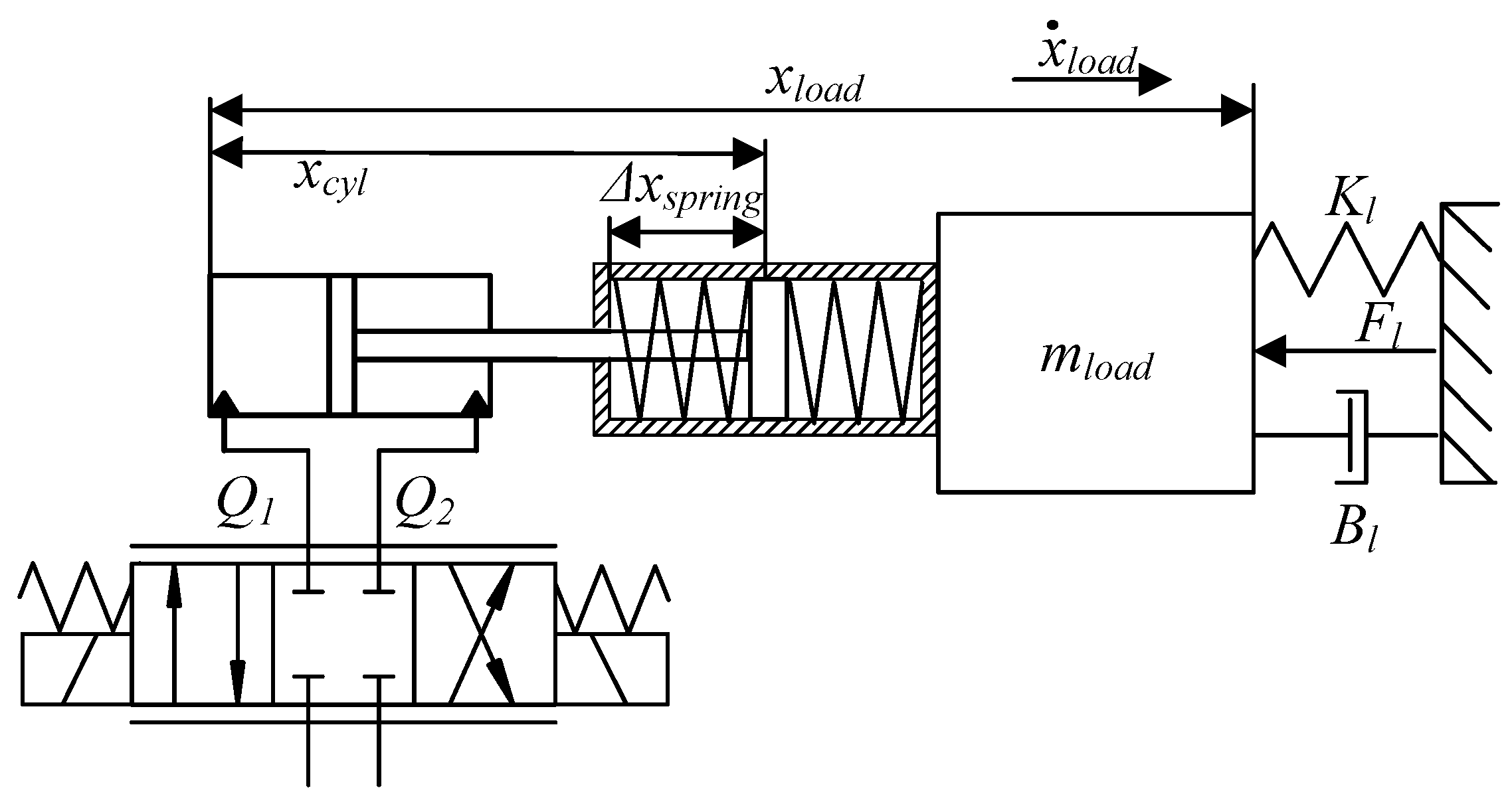
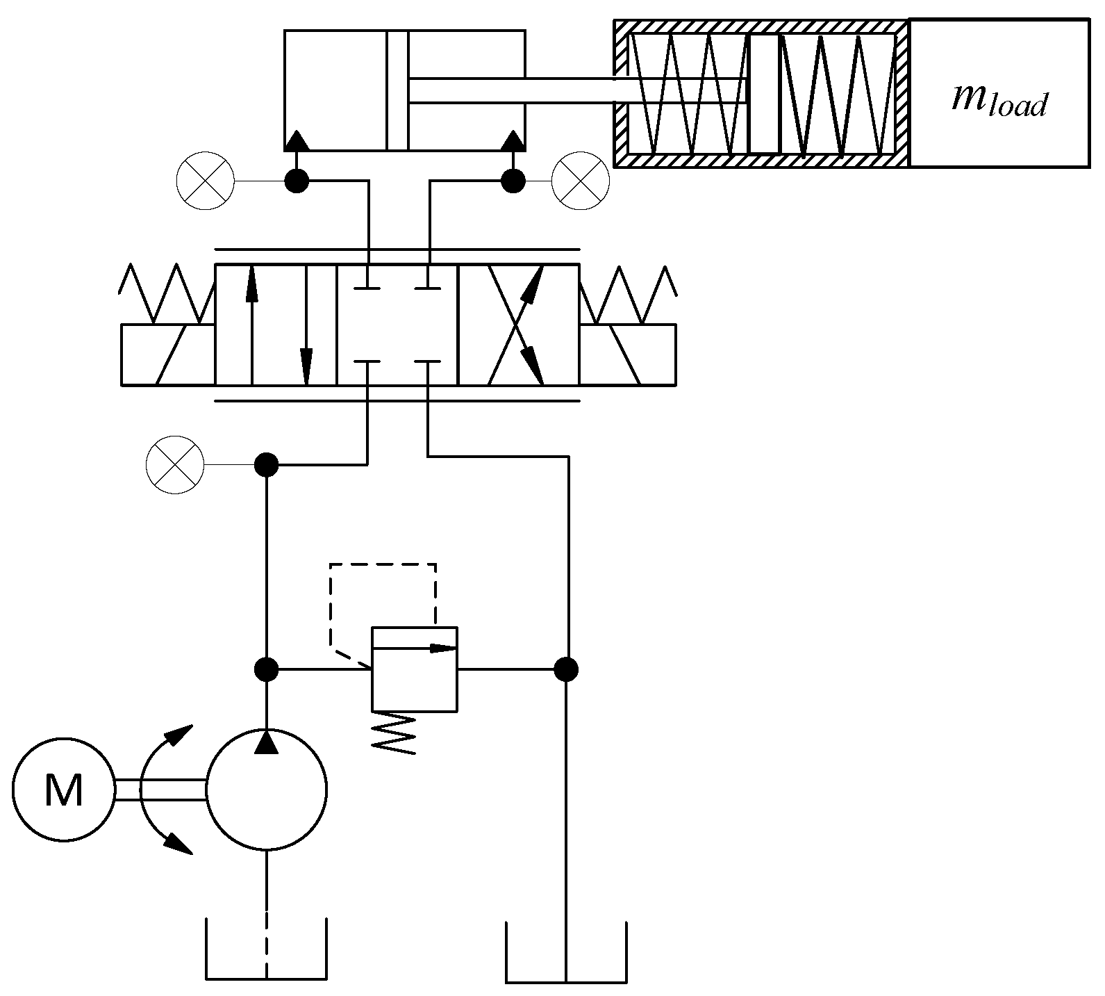
2. Modeling of the Hydraulic Series Elastic Actuator

SEAs use a spring in series with an actuator to decouple the actuator from the environment. As illustrated in Figure 1, the HSEA consists of a hydraulic cylinder with a mechanical spring and a hydraulic servo-valve. In Figure 1, the spring output force is symmetric in both directions to the symmetry of the spring stiffness. Therefore, the cylinder contact force can be estimated by measuring the spring compression. The hydraulic cylinder force can also be estimated via cylinder chamber pressures and cylinder areas. As Figure 1 shows, a 1-DOF HSEA is studied in a linear test case. Therefore, gravitational force does not affect the spring compression. In this study, spring compression, cylinder chamber pressures are measured, and cylinder position is measured. The supply pressure for the HSEA is 20 MPa.
In this study, the main focus is on designing a linear state feedback controller for the HSEA in Figure 1, to be used as an inner-loop controller for a outer-loop position-based impedance control. First, the fifth-order linear model for the HSEA is presented. Then, the state feedback controller for the system is defined. Finally, the selection of a spring for the HSEA is given.

2.1. State-Space Model for the HSEA

The linear model equations for the HSEA in Figure 1 can be derived by assuming that the hydraulic cylinder is symmetrical. Thus, the flow equations for a hydraulic servo-valve can be written as
Q 1 = A x ˙ c y l + C v p l + V 0 B e f f p ˙ 1
Q 2 = A x ˙ c y l + C v p l V 0 B e f f p ˙ 2
where A is the area of a symmetrical cylinder, B e f f is an effective bulk modulus, V 0 is half of the total volume of the hydraulic cylinder, C v is the total leakage coefficient of a piston, x ˙ c y l is the cylinder velocity, p 1 and p 2 are cylinder chamber pressures, p ˙ 1 and p ˙ 2 are the derivatives of cylinder pressures in both chambers, and p l = p 1 p 2 is the pressure difference in the cylinder.
The flow continuity Equations (1) and (2) can be linearized, by assuming that Q = Q 1 = Q 2 , as
Q = K q x v K c p l K q x v K c p l = x ˙ c y l A + C v p l + V 0 B e f f p ˙ 1 K q x v K c p l = x ˙ c y l A + C v p l V 0 B e f f p ˙ 2
Here, x v is the spool position of the hydraulic valve, K q is the servo-valve flow gain, and K c is the valve flow-pressure gain. In Equation (3), the servo-valve flow gain and valve flow pressure gain are used to linearize the flow-continuity equations. These gains can be defined by taking partial derivation of Equations (1) and (2):
K q = Q x v
K c = Q p l
Therefore, Equation (3) can be simplified as
p ˙ l = 2 A B e f f V 0 x ˙ c y l 2 K c e B e f f V 0 p l + 2 K q B e f f V 0 x v
where K c e = K c + C v is the total leakage coefficient in the cylinder.
Considering the HSEA in Figure 1, the dynamics equations for the system can be written as
m l x ¨ l o a d + B l x ˙ l o a d + ( K s + K l ) x l o a d K s x c y l + F l = 0
m c y l x ¨ c y l + B c y l x ˙ c y l + K s x c y l K s x l o a d A p l = 0
where m c y l is the mass of the piston, m l is the load mass, x l o a d is the load position, F l is the load contact force, B l and B c y l are the viscous damping coefficients of the load and the piston, K s is the spring stiffness, and K l is the spring stiffness of a load. In actual applications, the external load force and the damping of the environment are often absent. Therefore, coefficients K l and B l are neglected in this study.
Now, the state parameters for the HSEA can be defined by using Equations (3)–(8) as
x = [ x 1 x 2 x 3 x 4 x 5 ] = [ x l o a d x c y l x ˙ l o a d x ˙ c y l p l ]
Then, the state-space equations for the HSEA can be written as
x 1 = x 3 x 2 = x 4 x 3 = K s m l x 1 + K s m l x 2 x 4 = K s m c y l x 1 + K s m c y l x 2 B c y l m c y l x 4 + A m c y l x 5 x 5 = 2 B e f f A V 0 x 4 2 B e f f K c e V 0 x 5 + 2 B e f f K q V 0 u
where u is the control voltage to the hydraulic valve. In the hydraulic servo-valve, the spool position follows directly from the control voltage. Finally, Equation (10) can be rewritten as
A = 0 0 1 0 0 0 0 0 1 0 K s m l K s m l 0 0 0 K s m c y l K s m c y l 0 B c y l m c y l A m c y l 0 0 0 2 B e f f A V 0 2 B e f f K c e V 0
B = 0 0 0 0 2 B e f f K q V 0

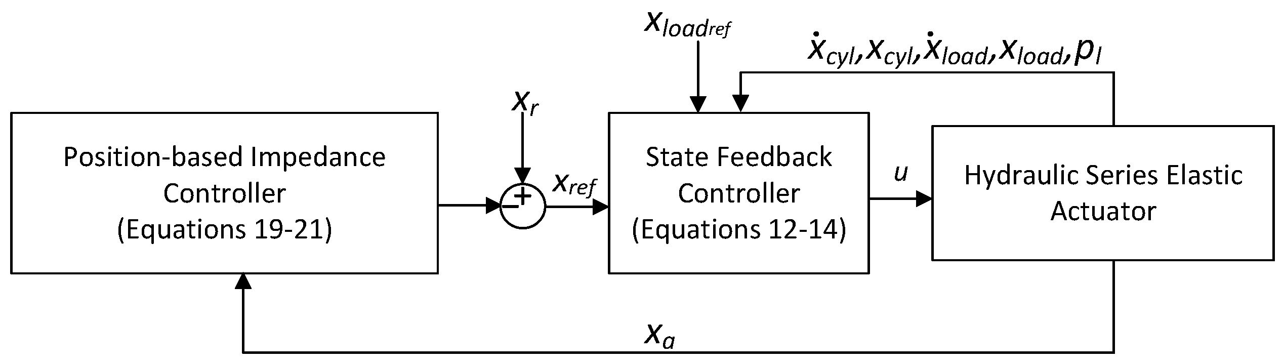
2.2. State Feedback Controller Design for the HSEA

According to Equations (10)–(12), the full state feedback controller for the HSEA can be presented based on the work in [24] as
u = K 1 ( x l o a d r e f x 1 ) K 2 ( x r e f x 2 ) + K 3 x 3 K 4 x 4 K 5 x 5
where the state feedback gains K 1 , K 2 , K 3 , K 4 , and K 5 are tuned such that the position error of the cylinder is minimized. In Equation (13), x l o a d r e f is desired position for load, which is provided as a reference trajectory to control system. Considering the fifth-order model for the HSEA in Equation (12), the proposed full-state feedback controller can be used to handle the dynamics of the HSEA system. The effectiveness of the proposed controller is verified by the experimental results.

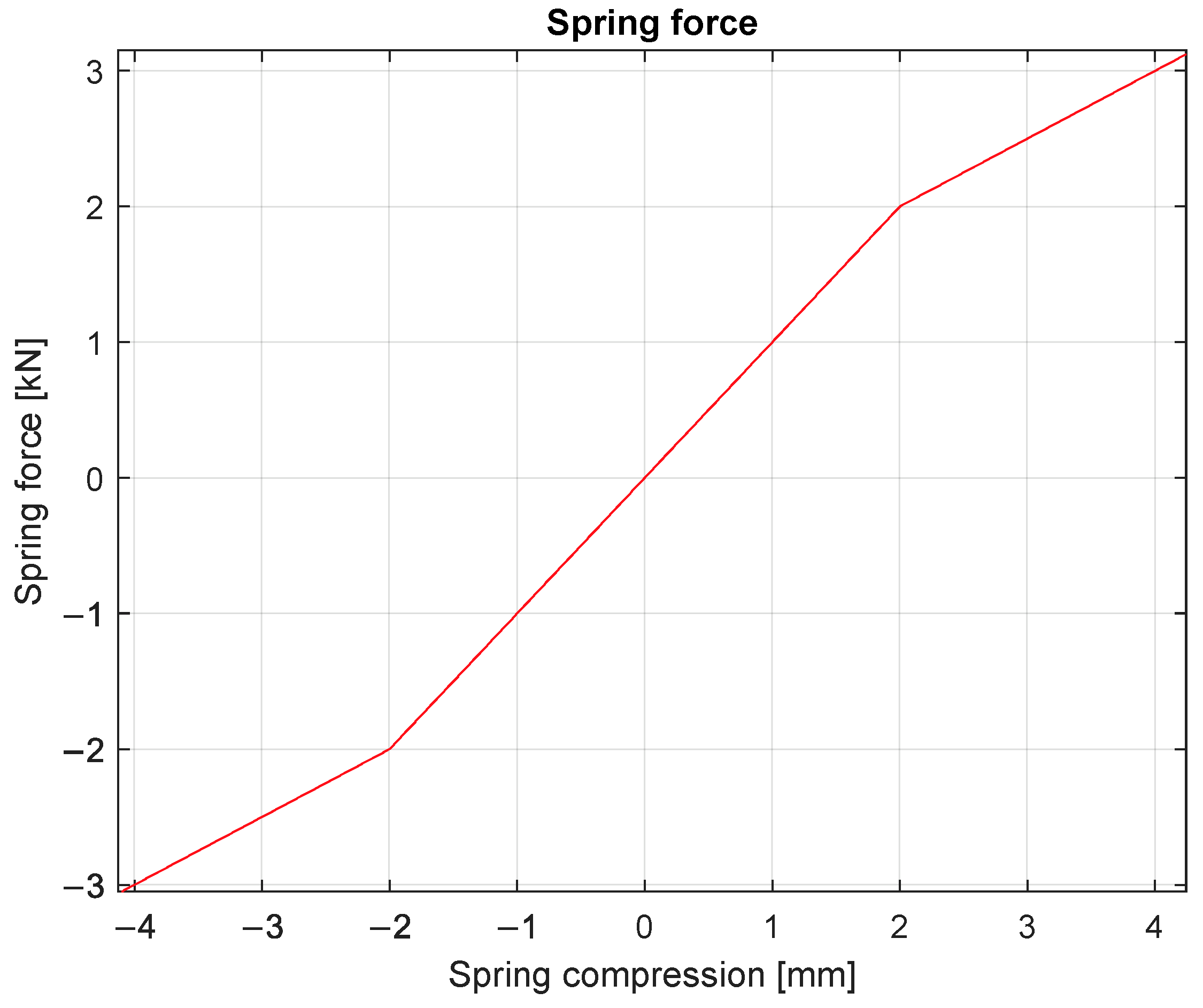
2.3. Stiffness and Natural Frequency of the HSEA

As Figure 1 illustrated, the HSEA consists of a normal spring connected in series to a hydraulic spring. By connecting elastic springs in a series, the effective stiffness reduces. Thus, the system’s equivalent stiffness can be presented as
1 K s y s = 1 K s + 1 K h y d
where K s y s is the system stiffness, K h y d is the hydraulic spring stiffness, and K s is the spring stiffness of normal. In Equation (14), the hydraulic stiffness can be defined by assuming that the pipes’ volumes are small compared to the cylinder chamber volume. The minimum hydraulic stiffness occurs when the cylinder piston is centered. Therefore, the stiffness can be calculated as
K h y d = 4 B e f f A 2 V t
The natural frequency of the HSEA can be presented by using Equations (14) and (15) as
ω n = K s y s m l
As reported in [5,8], increasing the equivalent spring stiffness of the SEA increases the force bandwidth. On the other hand, minimizing the non-linearities requires a low spring stiffness. Simultaneously, increasing spring stiffness also increases the system’s natural frequency. The purpose of the SEA is improving the contact-force control. Thus, the spring stiffness for the normal spring needs to be lower than the hydraulic stiffness. Considering heavy-duty manipulators with a low natural frequency (e.g., excavators and forwarders), the hydraulic resonance frequency is between 0.5 and 10 Hz. The selection of spring stiffness is a compromise for smooth response and force bandwidth.
The selected spring stiffness is illustrated in Figure 2. The selected spring stiffness is not linear due to the pre-tension length of the spring. The modeling parameters for the studied HSEA are presented in Table 1. Now, by substituting these parameters into Equations (14)–(16), we find that the value of the natural frequency is about 7.95 Hz.

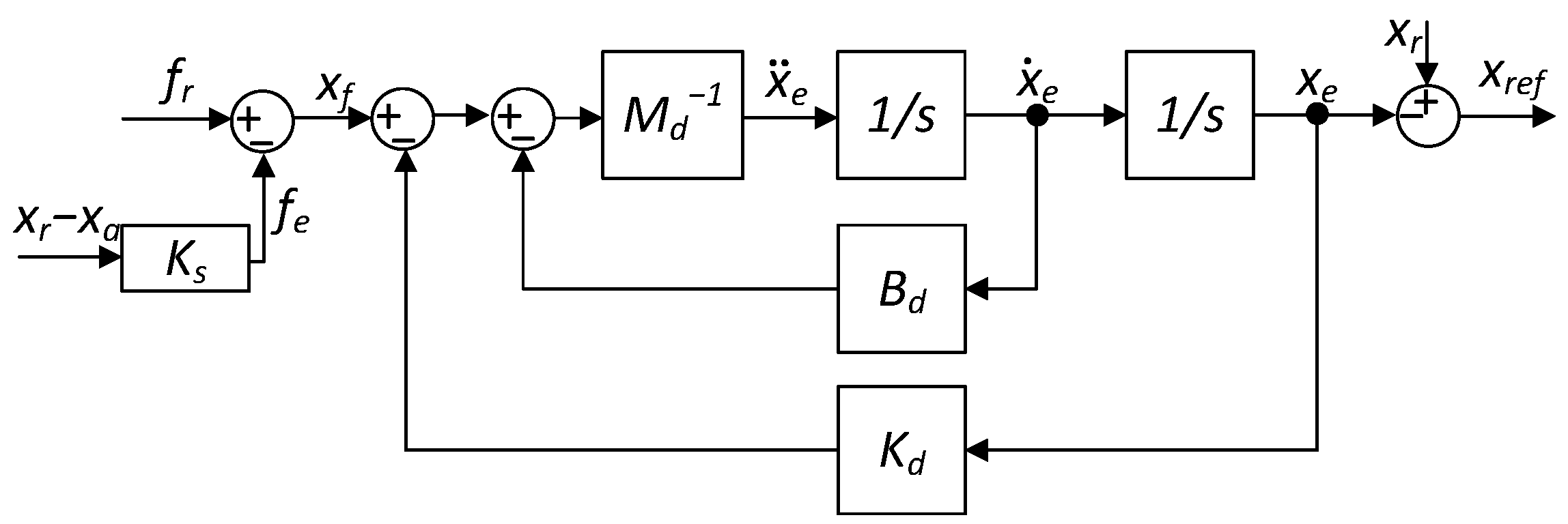
3. Position-Based Impedance Control Design

Hydraulic manipulators are used in many industrial tasks to move heavy loads. Their grip on different objects inevitably causes interaction with the environment. Here, high contact forces may stress a manipulator or an object’s mechanical structure. Therefore, impedance control design for these manipulators is needed. One method for implementing this for the HSEA is to use a position-based impedance controller using the cylinder position error to describe the cylinder contact force.
In Figure 1, the actual cylinder piston position is given by the cylinder piston position and the spring compression. Thus, the actual cylinder position can be calculated as
x a = x c y l + Δ x s p r i n g
where x c y l is a measured cylinder piston position and Δ x s p r i n g is a spring compression. Now, the cylinder contact force can be estimated by calculating the position difference between a desired cylinder position and a measured position as
f e = K s ( x r x a )
where K s is a spring stiffness, x r is a desired cylinder position, and f e is a contact force. The relation between a suitable position reference related to force error can be presented as
x f = f r f e
where f r is the desired contact force. In this study, f r is set to zero to minimize contact force.
The inverse dynamics control law with force measurement can be presented [22] as
x ¨ e = M d 1 ( B d x ˙ e + K d ( x e x f ) )
where M d , B d , and K d are the mass, damping, and stiffness matrices for the contact force dynamics, respectively, and x e is the contact compression. In Equation (20), the contact dynamics stiffness matrix is assumed to be same as the spring stiffness. Along the vertical direction, the contact dynamics can be presented as
M d = K d ω n 2
B d = ζ ( 2 K d M d )
where ω n is the natural frequency of the system and ζ is the defined damping factor.
Now, the position reference for an inner-loop controller can be written as
x r e f = x r x e
where x r is a desired load position, which is usually provided as an reference trajectory for the control system.
Finally, the proposed position-based impedance controller in Equations (18)–(20) can be presented with the block diagram in Figure 3. Now, the connection between the outer impedance controller and the inner state-feedback controller is shown in Figure 4. In Figure 4, the desired reference x r for a load position is generated with a point-to-point quintic reference trajectory. As Figure 4 demonstrates, in this study, we assume that all state variables for state-feedback controller can be measured.

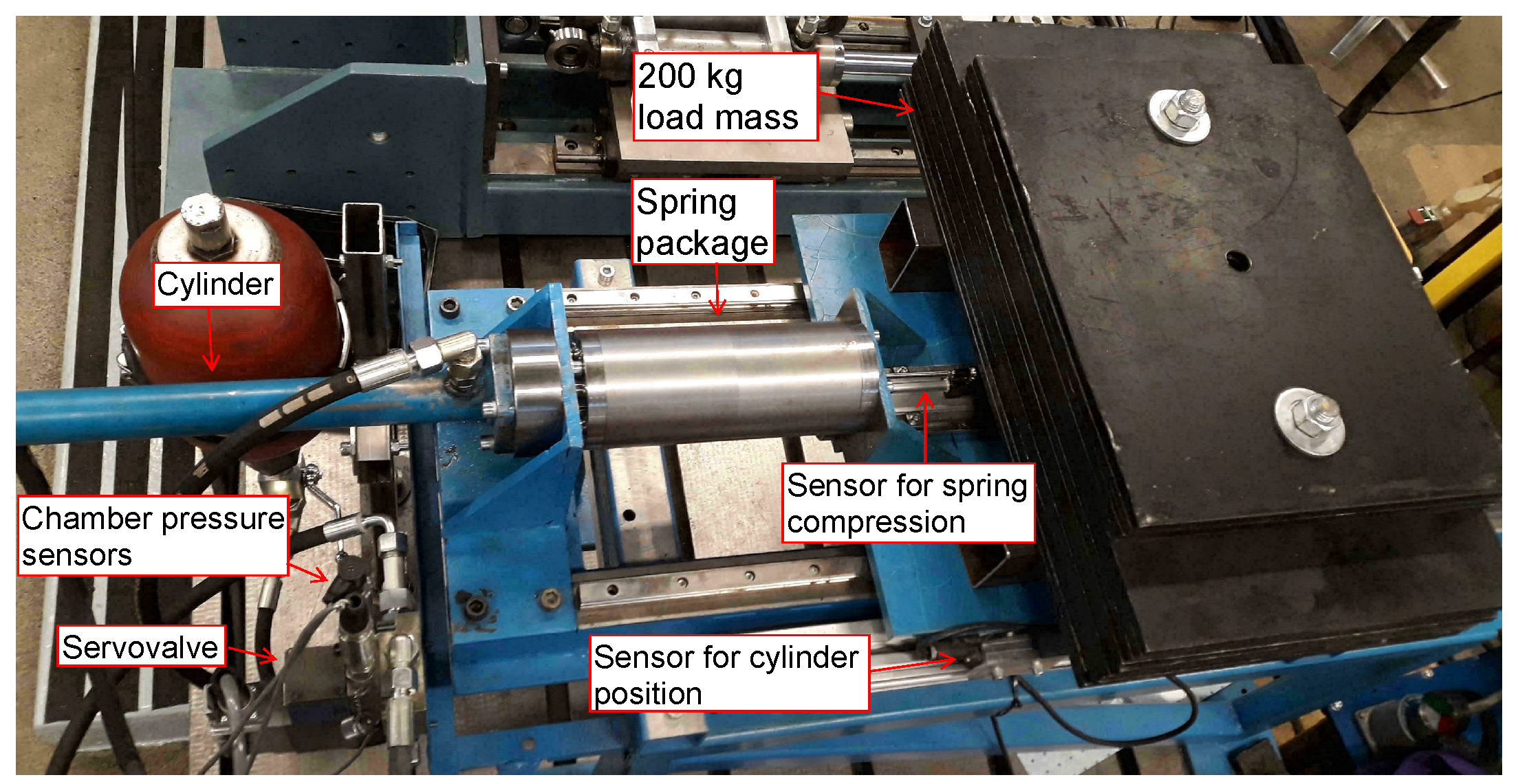
4. Experimental Results

The effectiveness of the proposed position-based impedance controller is verified by a full-scale 1-DOF experimental setup, which is presented in Figure 5. The experimental setup consists of the following hardware components:
  • Industrial PC Beckhoff CX2030 with a sampling rate of 1000 Hz
  • Hydraulic cylinder with the dimensions ϕ 32/18–400
  • Bosch Rexroth NG6 size servo solenoid valve (40 L/min at Δp = 3.5 MPa per notch)
  • Druck UNIK5000 pressure transmitter (range 25 MPa) for all pressures
  • MTS linear position sensor (range 0.015 m) for a spring compression
  • Heidenhain linear position sensor (range 0.54 m) for a cylinder position
  • Load mass 200 kg
  • Shell Tellus VG32 Hydraulic oil
In the experiments, the spring compression and cylinder position were measured using linear incremental position sensors. The hydraulic diagram for the experimental setup is presented in Figure 6. The supply pressure for the HSEA from the pump and the pressure relief were set to 20 MPa during the experiments.

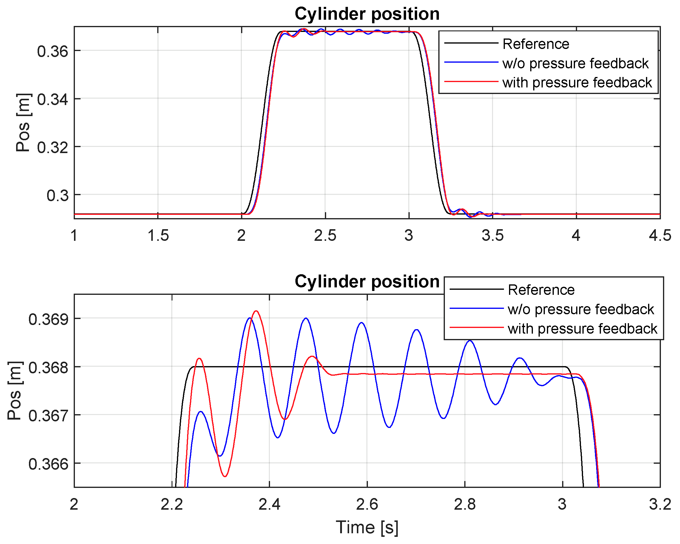
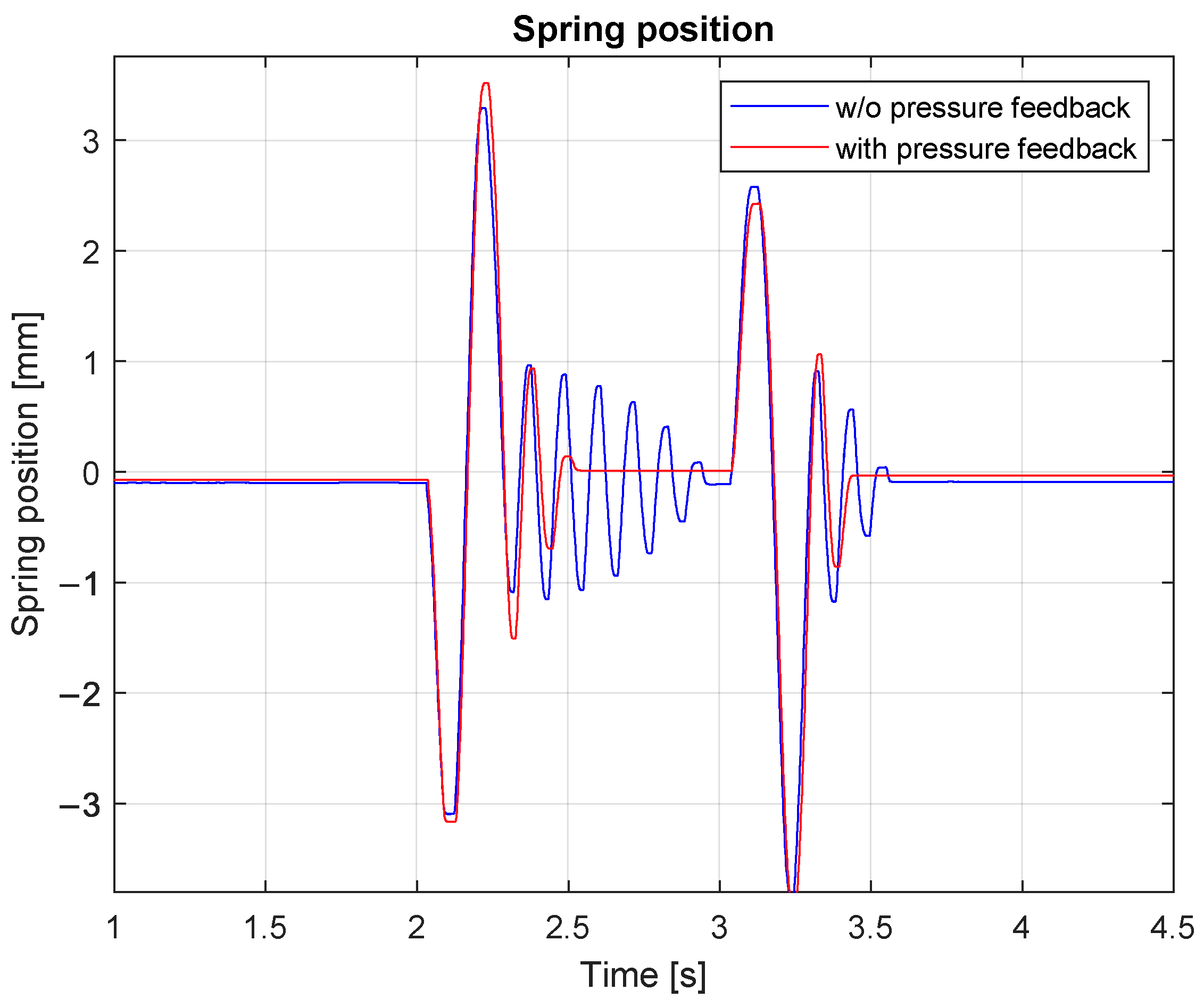
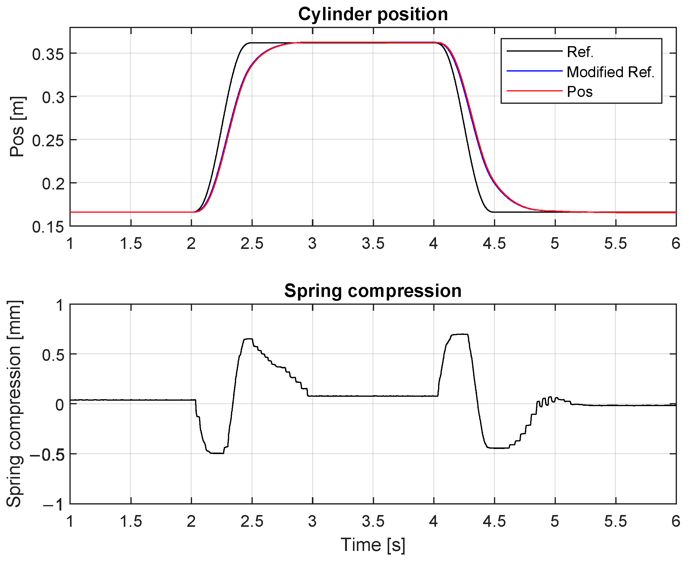
4.1. HSEA in a Free-Space Motion

First, the performance of the proposed controller was verified under free-space motion. Considering the HSEA system with heavy load, during a free-space motion, accelerations of the load could cause spring compression. In this case, we verify that the proposed controller can handle control of the HSEA system without contact motions and that proposed spring package can used to estimate the contact force.
In the HSEA, the system dynamics comprise slow system dynamics and fast spring dynamics simultaneously. Therefore, the fast inner-loop controller needs to handle the spring dynamics. In Figure 7, the HSEA was controlled using a step-like input for the cylinder position reference. As Figure 7 shows, the load pressure term in a state-feedback controller could be used to damp the oscillation of the spring. The corresponding spring compression is presented in Figure 8. As Figure 7 and Figure 8 show, the spring compression’s effects on the cylinder could be decreased using the proposed inner-loop controller. Considering the fast dynamics of the spring in Figure 8, the control results in Figure 7 verify that full-state feedback can be use to improve the control performance of the HSEA system. For this reason, a full model-based inner loop controller is needed to handle dynamics of the fifth-order HSEA system.
Figure 9 shows the results with the step-like position reference in free-space motion. The trajectory was designed so that valve control would be about 80% of its maximum. As Figure 9 shows, the proposed impedance controller affects the reference trajectory in a free-space motion due to spring compression. Even so, the system’s steady-state errors and compression were low, as demonstrated in Equation (14) which shows spring stiffness effect in relation to the total stiffness of the HSEA system. For this reason, the selection of the spring stiffness affect the system dynamics. As presented in Section 2.3, the spring selection should do according to the natural frequency of the system. Now, Figure 9 shows the selected spring stiffness thus selected achieves a high steady-state control performance when the total system stiffness is lower than that without the spring.
An SEA enables us to measure the cylinder force by using spring compression. In Figure 10, the cylinder force via spring stiffness (see Figure 2) and cylinder chamber pressures are presented when the impedance controller is not enabled. As Figure 10 shows, the spring force provides quite a smooth force measuring output. The cylinder force oscillates more during the transient motion. Moreover, cylinder friction and valve leakages affect the cylinder force. Considering, heavy-duty hydraulic systems, the cylinder force is typically estimated by using cylinder chamber pressures. Due to noisy pressure signals, it is typical that the estimated load force is noisy, which making force control of these kinds of systems difficult task. For these reason, measuring spring compression in HSEA systems allows contact force to be estimated without any force sensors.

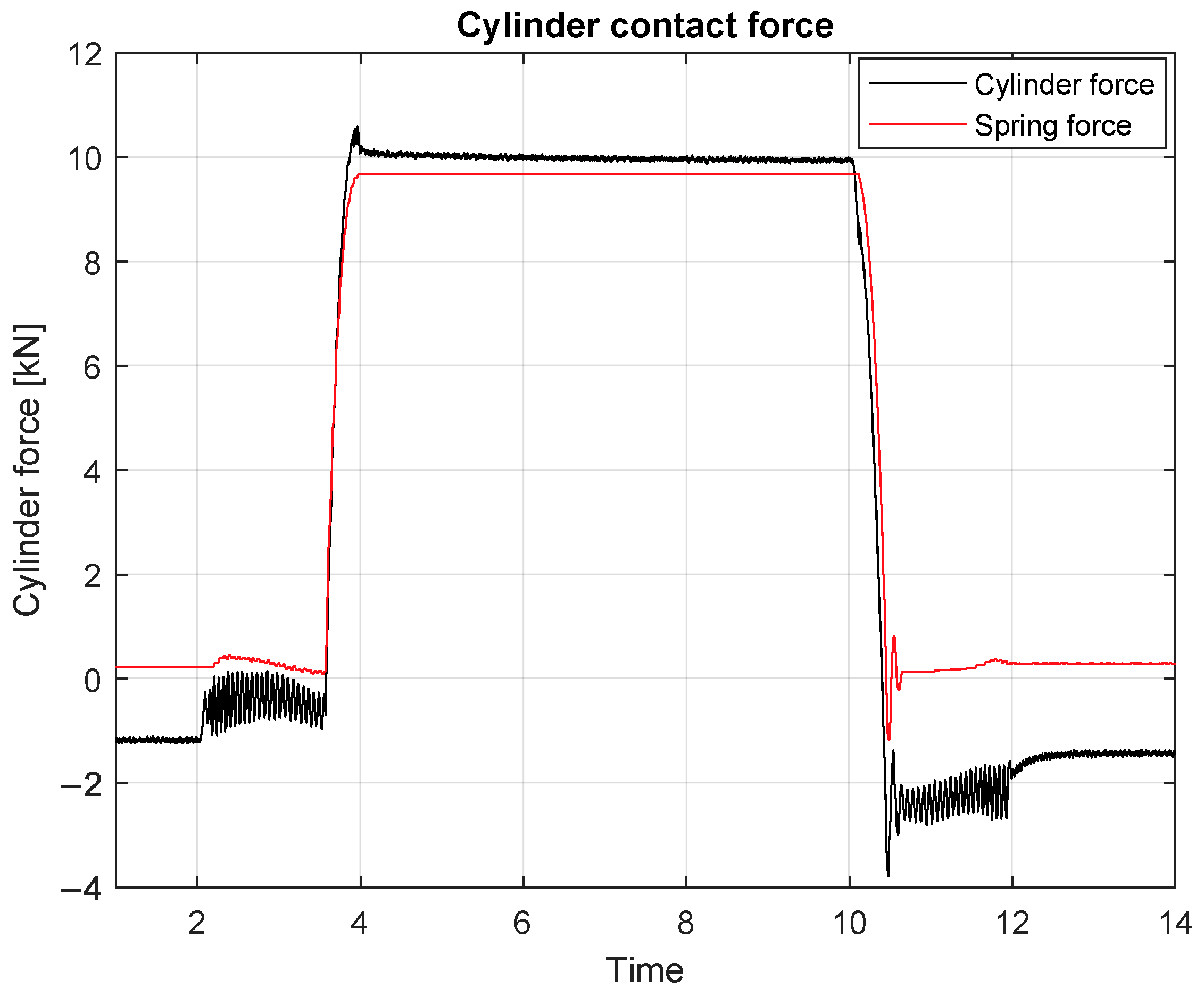
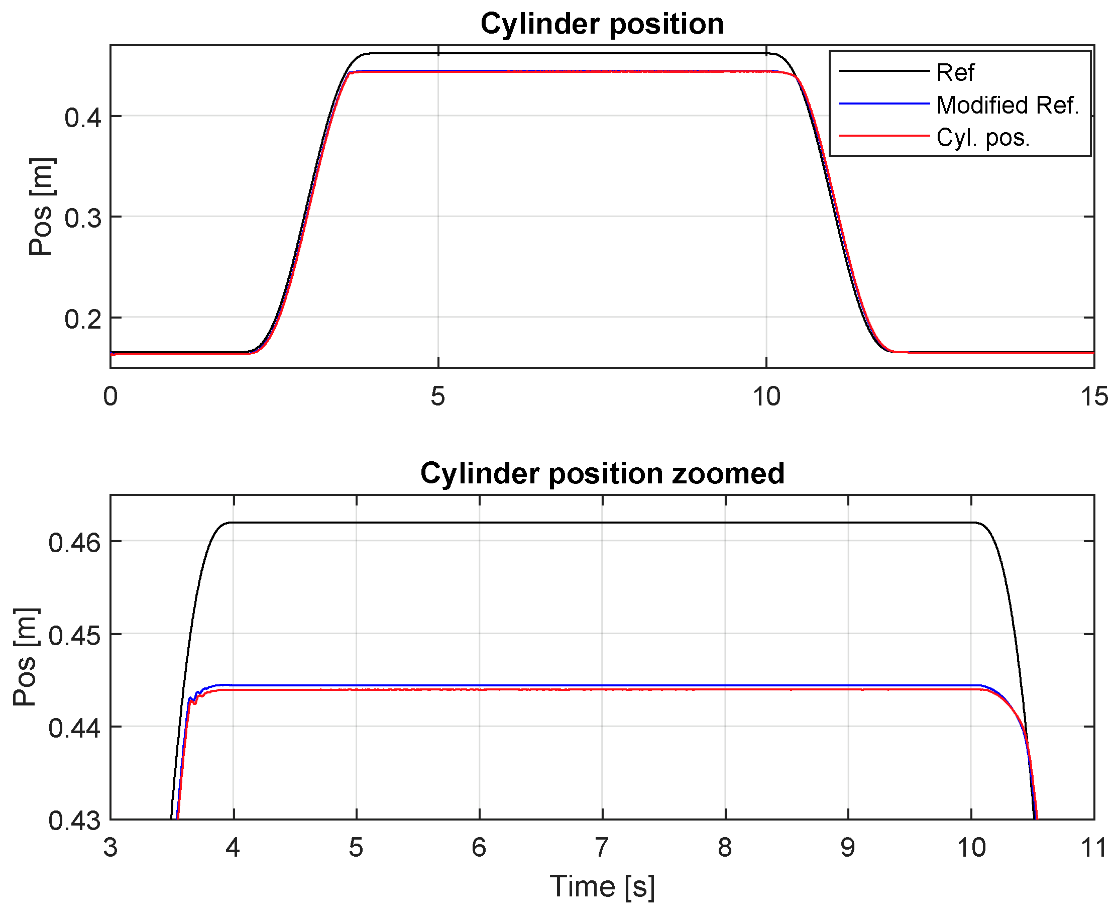
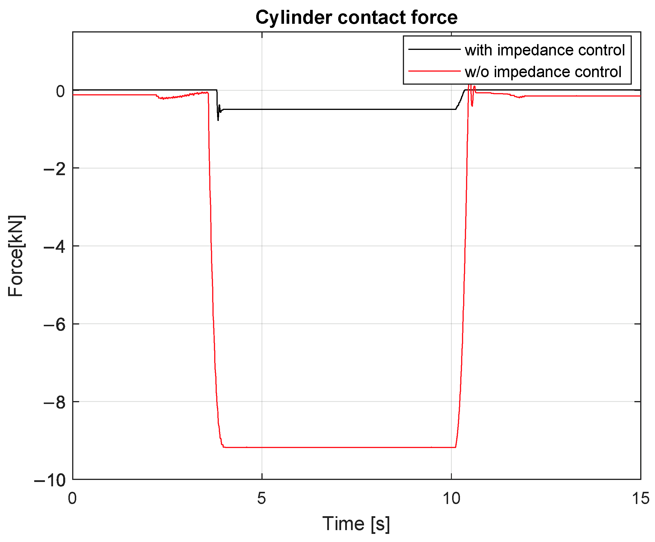
4.2. HSEA in a Contact Impedance Control Motion

The effectiveness of the proposed controller under contact impedance motion was verified by driving a cylinder against a rigid obstacle. Figure 11 displays a desired cylinder position reference, the position reference modified by impedance control (see Equation (23)), and the actual position during the impedance motion. The reference trajectory was designed so that the cylinder would be in contact with the environment for a period of ~7 s. As Figure 11 shows, the proposed controller could effectively compensate for the effect of the contact with the environment. The proposed controller’s effect on the cylinder’s contact force is presented in Figure 12 with the same reference as in Figure 11. As Figure 12 shows, the proposed controller could significantly decrease the cylinder contact force.
Finally, the effectiveness of the proposed controller is verified with various stiffness parameters in Equations (21) and (22). In Figure 13, the proposed control law in Equation (20) was tested with different contact force dynamics parameters, and it is shown that the proposed controller could also be used to compensate contact force effects in an environment with different contact stiffness. As the experimental results in Figure 13 demonstrate, the proposed HSEA system is robust against different environment stiffness.

5. Conclusions

This paper focuses on studying HSEAs for heavy-duty manipulation applications. As a novelty, the full state-feedback controller for the fifth-order HSEA system is presented. Second, the proposed state-feedback controller is combined with the position-based impedance control to handle HSEA system control during contact motion. The effectiveness of the proposed state-feedback controller is verified in free-space motion. As the experimental results show, the proposed full state-feedback controller can effectively handle the controlling of the fifth-order system. The experimental results also verify that the proposed position-based impedance control enables significantly decreasing the contact force of HSEA system during the contact motion. In general, the experimental results show that the proposed controller structure can efficiently handle control of a highly non-linear HSEA system with a heavy load in free-space and contact motions. In addition, the spring stiffness selection is presented in this paper and the experimental results verify that selected spring stiffness is working with heavy loads. These experimental results provide a baseline for our future studies, in which we intend to study the proposed HSEA with a position-based impedance controller will be studied with a real-size multi-DOF hydraulic manipulator. Moreover, the gravitational force effects on an HSEA will be studied.

Author Contributions

Conceptualization, P.M.; methodology, P.M.; software, P.M.; validation, P.M.; formal analysis, P.M.; investigation, P.M.; resources, P.M.; data curation, P.M.; writing—original draft preparation, P.M.; writing—review and editing, P.M.; visualization, P.M.; supervision, J.M.; project administration, J.M.; funding acquisition, J.M. All authors have read and agreed to the published version of the manuscript.

Funding

This research received no external funding.

Institutional Review Board Statement

Not Applicable.

Informed Consent Statement

Not Applicable.

Data Availability Statement

This study did not report any data. Further data can be provided upon email request to the corresponding author.

Conflicts of Interest

The authors declare no conflict of interest.

Nomenclature

SEASeries Elastic Actuator
HSEAHydraulic Series Elastic Actuator
DOFDegrees of Freedom
A Cylinder area (m2)
V 0 Half of the total cylinder volume (m3)
x c y l Cylinder length (m)
x ˙ c y l Cylinder velocity (m/s)
d c y l Cylinder diameter (m)
d p i s t o n Cylinder piston diameter (m)
m l Load mass (kg)
l c y l Cylinder stroke (m)
B e f f Cylinder bulk modulus (MPa)
B l Viscous damping coefficients of load (N/m/s)
x v Spool position of the hydraulic valve (m)
K q Servo-valve flow gain (m2/s)
K c Valve flow-pressure gain (m5/Ns)
K c e Total leakage coefficient of a cylinder m5/(Ns)
p 1 Cylinder A chamber pressure (MPa)
p 2 Cylinder B chamber pressure (MPa)
p l Cylinder chambers pressure difference (MPa)
F l Load contact force (N)
m c y l Cylinder mass (kg)
C v Total leakage coefficient of a piston m5/(Ns)
B c y l Viscous damping coefficients of piston (N/m/s)
Δ x s p r i n g Spring compression (m)
x l o a d Load position (m)
x l o a d r e f Desired position for load (m)
x ˙ l o a d Load velocity (m/s)
K s y s System total spring stiffness (N/m)
K h y d Hydraulic system spring stiffness (N/m)
K s Spring stiffness (N/m)
x f Relation between a suitable position reference related to force error
f r Desired contact force (N)
f e Contact force (N)
uValve control voltage (V)
M d Mass matrix
B d Damping matrix
K d Stiffness matrix
ω n Natural frequency of the system (rad/s)
ζ Damping factor

References

  1. Albu-Schäffer, A.; Ott, C.; Hirzinger, G. A unified passivity-based control framework for position, torque and impedance control of flexible joint robots. Int. J. Robot. Res. 2007, 26, 23–39. [Google Scholar] [CrossRef]
  2. Loughlin, C.; Albu-Schäffer, A.; Haddadin, S.; Ott, C.; Stemmer, A.; Wimböck, T.; Hirzinger, G. The DLR lightweight robot: Design and control concepts for robots in human environments. Ind. Robot. Int. J. 2007, 34, 376–385. [Google Scholar] [CrossRef] [Green Version]
  3. Albu-Schaffer, A.; Ott, C.; Frese, U.; Hirzinger, G. Cartesian impedance control of redundant robots: Recent results with the DLR-light-weight-arms. In Proceedings of the 2003 IEEE International Conference on Robotics and Automation (Cat. No. 03CH37422), Taipei, Taiwan, 14–19 September 2003; Volume 3, pp. 3704–3709. [Google Scholar] [CrossRef]
  4. Chen, T.; Casas, R.; Lum, P.S. An Elbow Exoskeleton for Upper Limb Rehabilitation with Series Elastic Actuator and Cable-Driven Differential. IEEE Trans. Robot. 2019, 35, 1464–1474. [Google Scholar] [CrossRef] [PubMed]
  5. Pratt, G.A.; Williamson, M.M. Series elastic actuators. In Proceedings of the 1995 IEEE/RSJ International Conference on Intelligent Robots and Systems, Human Robot Interaction and Cooperative Robots, Pittsburgh, PA, USA, 5–9 August 1995; Volume 1, pp. 399–406. [Google Scholar] [CrossRef] [Green Version]
  6. Lee, B.; Knabe, C.; Orekhov, V.; Hong, D. Design of a human-like range of motion hip joint for humanoid robots. In Proceedings of the ASME 2014 International Design Engineering Technical Conferences and Computers and Information in Engineering Conference, Buffalo, NY, USA, 17–20 August 2014. [Google Scholar] [CrossRef] [Green Version]
  7. Budolak, D.; Ben-Tzvi, P. Series elastic actuation for improved transparency in time delayed haptic teleoperation. Mechatronics 2019, 63, 102278. [Google Scholar] [CrossRef]
  8. Robinson, D.W.; Pratt, J.E.; Paluska, D.J.; Pratt, G.A. Series elastic actuator development for a biomimetic walking robot. In Proceedings of the 1999 IEEE/ASME International Conference on Advanced Intelligent Mechatronics (Cat. No. 99TH8399), Atlanta, GA, USA, 19–23 September 1999; pp. 561–568. [Google Scholar] [CrossRef]
  9. Pratt, J.; Krupp, B.; Morse, C. Series elastic actuators for high fidelity force control. Ind. Robot. Int. J. 2002, 29, 234–241. [Google Scholar] [CrossRef]
  10. Pratt, J.E.; Krupp, B.T. Series elastic actuators for legged robots. In Proceedings of the Unmanned Ground Vehicle Technology VI, International Society for Optics and Photonics, Orlando, FL, USA, 13–15 April 2014; Volume 5422, pp. 135–144. [Google Scholar] [CrossRef]
  11. Kaminaga, H.; Otsuki, S.; Nakamura, Y. Development of high-power and backdrivable linear electro-hydrostatic actuator. In Proceedings of the 2014 IEEE-RAS International Conference on Humanoid Robots, Atlanta, GA, USA, 18–20 November 2014; pp. 973–978. [Google Scholar] [CrossRef]
  12. Oh, S.; Kong, K. High-precision robust force control of a series elastic actuator. IEEE/ASME Trans. Mechatron. 2016, 22, 71–80. [Google Scholar] [CrossRef]
  13. Zhao, Y.; Paine, N.; Jorgensen, S.J.; Sentis, L. Impedance control and performance measure of series elastic actuators. IEEE Trans. Ind. Electron. 2017, 65, 2817–2827. [Google Scholar] [CrossRef]
  14. Calanca, A.; Fiorini, P. Understanding environment-adaptive force control of series elastic actuators. IEEE/ASME Trans. Mechatron. 2018, 23, 413–423. [Google Scholar] [CrossRef]
  15. Robinson, D.W.; Pratt, G.A. Force controllable hydro-elastic actuator. In Proceedings of the 2000 ICRA. Millennium Conference. IEEE International Conference on Robotics and Automation. Symposia Proceedings (Cat. No. 00CH37065), San Francisco, CA, USA, 24–28 April 2000; Volume 2, pp. 1321–1327. [Google Scholar] [CrossRef]
  16. Paine, N.; Oh, S.; Sentis, L. Design and control considerations for high-performance series elastic actuators. IEEE/ASME Trans. Mechatron. 2013, 19, 1080–1091. [Google Scholar] [CrossRef] [Green Version]
  17. Mattila, J.; Koivumäki, J.; Caldwell, D.G.; Semini, C. A survey on control of hydraulic robotic manipulators with projection to future trends. IEEE/ASME Trans. Mechatron. 2017, 22, 669–680. [Google Scholar] [CrossRef]
  18. Cao, X.; Aref, M.M.; Mattila, J. Design and Control of a Flexible Joint as a Hydraulic Series Elastic Actuator for Manipulation Applications. In Proceedings of the 2019 IEEE International Conference on Cybernetics and Intelligent Systems (CIS) and IEEE Conference on Robotics, Automation and Mechatronics (RAM), Bangkok, Thailand, 18–20 November 2019; pp. 553–558. [Google Scholar] [CrossRef]
  19. Zhong, H.; Li, X.; Gao, L.; Dong, H. Position Control of Hydraulic Series Elastic Actuator with Parameter Self-Optimization. In Proceedings of the 2019 IEEE 4th International Conference on Advanced Robotics and Mechatronics (ICARM), Toyonaka, Japan, 3–5 July 2019; pp. 42–46. [Google Scholar] [CrossRef]
  20. Zhong, H.; Li, X.; Gao, L. Adaptive Delay Compensation for Admittance Control of Hydraulic Series Elastic Actuator. In Proceedings of the 2020 IEEE 16th International Conference on Automation Science and Engineering (CASE), Hong Kong, China, 20–21 August 2020; pp. 384–389. [Google Scholar] [CrossRef]
  21. Zhong, H.; Li, X.; Gao, L.; Dong, H. Development of Admittance Control Method with Parameter Self-optimization for Hydraulic Series Elastic Actuator. Int. J. Control Autom. Syst. 2021, 19, 2357–2372. [Google Scholar] [CrossRef]
  22. Sciavicco, L.; Siciliano, B. Modelling and Control of Robot Manipulators; Springer Science & Business Media: London, UK, 2012. [Google Scholar] [CrossRef]
  23. Kaixin, S.; Cong, Z.; YueHua, C.; Jing, W.; Qing, W.; HongXu, M. Impedance control of hydraulic series elastic actuation. In Proceedings of the 2020 Chinese Automation Congress (CAC), Shanghai, China, 6–8 November 2020; pp. 2393–2398. [Google Scholar] [CrossRef]
  24. Dorf, R.C.; Bishop, R.H. Modern Control Systems; Pearson: Upper Saddle River, NJ, USA, 2011. [Google Scholar]
  25. Mustalahti, P.; Mattila, J. Impedance Control of Hydraulic Series Elastic Actuator with a Model-Based Control Design. In Proceedings of the 2020 IEEE/ASME International Conference on Advanced Intelligent Mechatronics (AIM), Boston, MA, USA, 6–9 July 2020; pp. 966–971. [Google Scholar] [CrossRef]
Figure 1. Schematic diagram of a HSEA.
Energies 15 02503 g001
Figure 2. Spring force as a function of spring compression. Adapted with permission from [25]. Copyright 2020 IEEE.
Energies 15 02503 g002
Figure 3. Block diagram for the position-based impedance controller.
Energies 15 02503 g003
Figure 4. Control system block diagram.
Energies 15 02503 g004
Figure 5. HSEA experimental setup.
Energies 15 02503 g005
Figure 6. Hydraulic diagram for the experimental setup.
Energies 15 02503 g006
Figure 7. Cylinder position under free-space motion.
Energies 15 02503 g007
Figure 8. Spring compression in a free-space motion.
Energies 15 02503 g008
Figure 9. Cylinder position and spring compression in a free-space motion.
Energies 15 02503 g009
Figure 10. Spring force and cylinder pressure in a contact.
Energies 15 02503 g010
Figure 11. Cylinder position under contact motion.
Energies 15 02503 g011
Figure 12. Spring compression with and without impedance control.
Energies 15 02503 g012
Figure 13. Spring compression with a different stiffness.
Energies 15 02503 g013
Table 1. Parameter values for the HSEA.
SymbolValue
d c y l 32 × 10 3 m
d p i s t o n 18 × 10 3 m
m l 200 kg
l c y l 0.4 m
B e f f 900 MPa
m c y l 2 kg
C v 1.16 × 10 12 m5/Ns
K q 6.7 × 10 4 m2/s
K c 2.5 × 10 −12 m5/Ns
Publisher’s Note: MDPI stays neutral with regard to jurisdictional claims in published maps and institutional affiliations.

