Abstract
Temporary internal water pressure (IWP) during a construction period fundamentally affects the structural performance of spiral case structures (SCSs) in pumped-storage power plants (PSPPs). However, its actual role is rarely studied. This study focuses on this issue considering the complex construction-to-operation process of SCSs. An ABAQUS-based complete simulation procedure (CSP) is used with contact non-linearity considered. The contact-closing ratio is introduced to quantitively describe the contact status, and different design philosophies for temporary IWP are compared. The results show that the temporary IWP should be no greater than 80% of the minimum static headwater to ensure an overall contact-closing status under normal operating conditions in this study. The findings reveal that the cracking risk of concrete is negatively correlated with temporary IWP, while high temporary IWP is not suggested. Moreover, the stay ring actually shares a certain part of the unbalanced hydraulic thrust, which cannot be ignored. The limitation of this study might mainly lie in the idealized linear-elastic description of concrete. The temporary IWP should be designed with overall consideration of the IWP under normal operating conditions, the IWP-jointly-resisting status and design demands.
1. Introduction
With ambitious commitments on net zero emissions made at the 26th Conference of the Parties (COP26), the transition to clean energy has accelerated worldwide, which accordingly triggers a boost in hydropower development [1,2]. Meanwhile, to make up for the limitations of clean energy, the pumped-storage power plant (PSPP) serves as a well-established technology in energy storage for its best cost-efficiency combination [3,4,5].
A PSPP operates by pumping and releasing water between a higher elevation reservoir and a lower one. During a low electrical consumption period, surplus electricity from the power grid is transformed to potential energy of water with PSPP. The demand for energy storage is, thus, achieved. When electrical consumption rises, PSPP works as a regular hydroelectric power plant (HPP) to feed electricity into the power grid. In general, PSPPs tend to use high-head, high-frequency and large-output pump turbine sets. Therefore, it is inevitable that the pump turbine set where energy transformation happens becomes a significant part of PSPP [6,7].
Moreover, with the development of engineering practices [8] and theory study [9], a design philosophy focusing on the safe and reliable operation of pump turbine set is proposed. The design philosophy clarifies the core position of the pump turbine set, thus introducing a new perspective in the design, construction and operation process of PSPPs for researchers and practitioners [10].
To provide steady and uniform water flow in the pump turbine, the spiral case structure (SCS), which is located at the end of the conduit and is the closest to the turbine, is of critical importance. The SCS normally consists of mass concrete with engineered reinforcement and a steel liner, which is often referred to as the steel spiral case (SSC). Based on the methods of embedment of SSC in concrete, there are generally three types of SCSs, which are the P-type SCS, M-type SCS and N-type SCS. The P-type SCS stands for the method that where SSC is embedded in concrete under temporarily water-pressurized condition, while the M-type SCS and N-type SCS are embedded under an unwatered condition. The difference between the M-type and N-type SCSs is that the N-type SCS is embedded in a natural state, while the M-type SCS has a compressible membrane covering the SSC [11].
In modern engineering practices, P-type SCSs are adopted in most PSPPs for its abundant engineering examples [12]. The standard construction process of P-type SCSs and an in-field scene of it are shown in Figure 1. The first-phase concrete and pedestal of the SSC are constructed previously to provide necessary support for the SSC. Then, the SSC is placed in position and sealed with the test head and test barrel. The test head is set at the inlet of the SSC, and the test barrel is set between the upper and lower stay rings. Meanwhile, the SSC is fixed to the concrete with tie rods around it to prevent the uplift of SSC during the construction of the second-phase concrete. Then, temporary internal water pressure (IWP) is specified in the SSC, and second-phase concrete is constructed with the SSC under pressurized condition. Finally, after the set of second-phase concrete, the temporary IWP is released, the sealing devices are removed and the construction of a P-type SCS is, thus, finished.
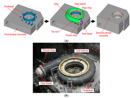
Figure 1.
P-type SCSs: (a) construction process; (b) scene of the temporary pressurization for the SSC.
The aim of the complex construction process of P-type SCSs is to produce an initial gap between the SSC and the concrete. Considering the poor tensile resistance of concrete, SSC is designed to resist a major part of IWP. Therefore, the existence of the initial gap makes it possible to divide the structural load between the SSC and the concrete, and it benefits maximizing the two construction materials’ strengths. Since temporary IWP is a direct determinant of the initial gap, it is easy to understand that temporary IWP has a strong influence on the load-bearing characteristics of SCS.
Focusing on structural bearing capacity, researchers have conducted plenty of instructive work on P-type SCSs, considering multiple factors including crack propagation and effect [13,14,15], application and the modification of the finite element method (FEM) [16,17,18,19,20] and dynamic characteristics [21,22]. Despite the important structural role of temporary IWP, unfortunately, a key problem with most previous studies is that they failed to focus on its effect during the entire construction-to-operation process. Correspondingly, it is the motivation and aim of this work to investigate the actual effect of temporary IWP.
However, the complex construction process of P-type SCSs brings about high numerical-reproducing difficulty for it. More importantly, physically modeling it is time consuming and costly. Therefore, with a validated complete simulation procedure (CSP) technique proposed by the authors [20], this study focuses on temporary IWP, aiming to figure out its actual role in the construction-to-operation process and its effect on the structural performance of SCS. This study will provide engineers and practitioners with fresh insight concerning the design of the temporary IWP for P-type SCSs.
2. Overview of P-Type SCSs
2.1. The IWP-Jointly-Resisting Status of P-Type SCSs
The initial design philosophy for P-type SCSs is mainly attributed to (a) the hydrostatic test required by the American design code of pressure vessels and (b) considering the temporary IWP as a deciding threshold for the SSC-concrete contact status.
Based on the threshold assumption, it is believed that (a) SSC expands during pressurization and shrinks after unwatering, thus producing an initial gap between the SSC and concrete; (b) when the operating IWP is specified to be lower than the temporary IWP, the SSC and the concrete are isolated by the initial gap, and the SSC resists the operating IWP independently; and (c) when the operating IWP reaches the temporary IWP, the initial gap closes perfectly, and the SSC and the concrete jointly resist IWP. This final status is normally referred to as the IWP-jointly-resisting status.
In others words, the gap between the SSC and the concrete is considered a barrier that prevents IWP being transmitted into the concrete too much. Therefore, temporary IWP plays an important role in breaking up the IWP bearing of an SCS, and it fundamentally decides the IWP-resisting percentages of the SSC and the concrete.
Unfortunately, field monitoring data and numerical studies have revealed that the IWP-jointly-resisting status of SCSs is not what engineers expected [23]. Researchers have observed the untimely and delayed gap-closing phenomenon, which has been reproduced in numerical analysis based on multiple different cases. This phenomenon reveals that the SSC has already come into contact with the concrete before the operating IWP reaches the temporary IWP, and the gap between the SSC and the concrete does not close completely, when the operating IWP exceeds the temporary IWP. This phenomenon indicates that the effect of the temporary IWP is never a simple threshold issue, and it is believed to be rooted in the complex construction routine of P-type SCSs [24,25,26,27,28].
2.2. The Design Philosophy for Temporary IWP
When it comes to the design of temporary IWP, engineers and practitioners from different countries and regions have different understandings. American engineers tend to design the temporary IWP to be greater than or equal to the maximum design pressure (MDP), as U.S. Army Corps of Engineers [29] suggested. In this condition, a major part of the operating IWP is believed to be resisted by the SSC itself.
In contrast, European and Chinese engineers have some concerns about the structural integrity of SCS. Consequently, they follow an IWP jointly resisting design philosophy where the SSC and the concrete jointly resist the operating IWP. Therefore, the temporary IWP is often specified as 60 to 80 percent of the minimum static headwater in Europe, and it is suggested to be specified as 60 to 80 percent of the maximum static headwater in Chinese design codes for hydropower houses [30].
Table 1 presents the globally adopted temporary IWPs of several typical PSPPs/HPPs. It is easy to realize that the temporary IWPs of all three Chinese PSPPs are around 75 percent of the minimum static headwater and around 70 percent of the maximum static headwater as well, which meets both Chinese and European design codes. Actually, in Chinese engineering practice, there is a general consensus that the temporary IWP should be specified as 50 percent of the MDP, and all three Chinese PSPPs in Table 1 were actually designed following this consensus. The Grand Coulee Third Power Plant was completed in 1975, and its temporary IWP was chosen to be slightly over the maximum static headwater. Tehri PSPP has a wide variation in water head, and its temporary IWP was chosen around 45 percent of the MDP.

Table 1.
The adopted temporary IWP of several typical PSPPs/HPPs worldwide.
The reason for the discrepancy in the design philosophy for temporary IWP is actually rather comprehensible. The major purpose of American design philosophy is to eliminate the cracking risk of concrete. Therefore, with the temporary IWP specified to be equal to MDP, the SSC is highly unlikely to ever come into contact with the concrete, and the concrete merely provides the necessary structural support for SSC. However, Chinese designers tend to maintain better structural integrity of the composite system, and certain contact pressure is expected between the SSC and the concrete. In this condition, with the proper design of the temporary IWP, the IWP-resisting percentage of the concrete is expected to be restrained at an acceptable level.
However, these assumptions above are mainly based on engineering practices, and the actual effect of temporary IWP is rarely studied. Contrary to traditional knowledge, the effect of the temporary IWP and its actual role can be rather complicated. Because of the untimely and delayed gap-closing phenomenon of the SSC-concrete contact, the current practice-based design philosophy for temporary IWP can be error prone and may result in more uncertainty concerning this issue.
To better illustrate the structure of this study, a flowchart is shown in Figure 2. This study focuses on the IWP-jointly-resisting status of the SCS under different temporary IWPs, and the effect of temporary IWP is assessed through several typical aspects of structural performance.
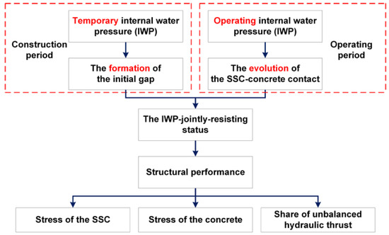
Figure 2.
Flowchart of this study.
3. Numerical Study
3.1. Project Profile of Meizhou PSPP
A P-type SCS of the Meizhou PSPP located in Guangdong province, China, is chosen as the object of the current numerical study. Meizhou PSPP has eight pump turbine sets, and each set has a capacity of 300 MW, totaling to a capacity of 2400 MW. The diameter of the inlet of the SSC is 2.5 m. The maximum and minimum liner thicknesses of the SSC are 62 mm and 24 mm, respectively. The MDP of the SSC is 6.86 MPa, which is equal to the bursting pressure of maximum headwater plus water hammer under load rejection condition. Under normal operating condition, the operating IWP lies between the maximum and minimum static headwater, which is 4.91 MPa and 4.58 MPa. Figure 3 shows the plain layout of the SSC.
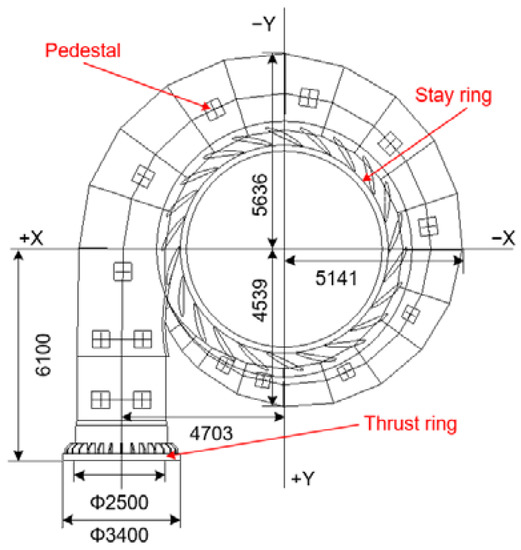
Figure 3.
Plain layout of the SSC.
3.2. FE Model and Material Parameters
The numerical study is based on the ABAQUS software. Figure 4 shows the FE model of the SCS, with part of the generator pedestal taken into consideration. The concrete, the thrust ring and the stay ring are modeled with C3D8 solid elements. The SSC, the test head, the internal steel liners of the generator pedestal and the draft tube and the fixed guide vanes of the stay ring are modeled with S4 shell elements. The tie rod is modeled with T3D2 truss elements. The consistent deformation of the SSC and the internal surface of the concrete during the construction process is simulated with CONN3D2 connector elements [20]. The model consists of 76,732 nodes and 116,383 elements. The typical element edge length is 0.1–0.75 m.
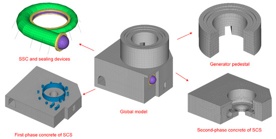
Figure 4.
FE model of the SCS.
Multiple sets of contact pairs are defined at the interfaces between the SSC and concrete structures. The classical coulomb friction model is adopted to simulate the interaction between the SSC and concrete structures. The friction coefficient is defined as 0.25 with overall consideration of the authors’ previous work, as well as the research of Rabbat and Russell [31], Baltay and Gjelsvik [32], Zhang [11], Hu [33] and Zhang [34].
The elastic modulus of the steel shells is taken as 206,000 MPa, the Poisson’s ratio is taken as 0.26 and the mass density is taken as 7850 kg/m3. The elastic modulus of the tie rod is taken as 206,000 MPa, the Poisson’s ratio is taken as 0.3, and the mass density is taken as 7850 kg/m3. The elastic modulus of concrete is taken as 30,000 MPa, the Poisson’s ratio as 0.167, and the mass density as 2500 kg/m3. Since the focus of this study is the temporary IWP and its effect, the concrete is described as linear-elastic, and the reinforced steel bar is neglected. Even though the FEA-predicted stress of the concrete is still informative and attention should be paid to the stress-concentration zone, where a higher risk of tensile cracking is indicated.
3.3. Loads and Boundary Conditions
To determine the effect of temporary IWP on structural performance, seven cases are considered with the temporary IWP ranging from 1.832 to 6.86 MPa. The temporary IWP of case 1 is specified to be equal to 40% of the minimum static headwater, which is even lower than the lower limit of European design philosophy. The aim of case 1 is to investigate the effect under extreme conditions. The temporary IWPs of cases 2–7 are chosen following different design philosophies. Table 2 presents the temporary IWPs of seven cases with brief illustrations.
Table 2.
Calculation cases.
First, the temporary IWP is specified in each case, respectively. Then, after the set of second-phase concrete and the release of temporary IWP, multiple static load steps are defined with the operating IWP from 0.343 to 6.86 MPa, simulating the entire pressurization and operating process of SSC. Considering the actual status of the structure, normal displacement constraints are applied to the bottom of the FE model.
3.4. Complete Simulation Procedure (CSP) and Its Validation
In this study, an ABAQUS-based complete simulation procedure (CSP) was adopted to simulate the complex construction-to-operation process of the SCS, aiming to investigate the effect of the temporary IWP during the entire procedure. The CSP has been put forward and validated in the authors’ previous work to solve the problems concerning complex SSC-concrete contact [20]. With proper adoption of the CONN3D2 connector elements and the function of model change, the construction routine of P-type SCSs can be well simulated and analyzed, thus making it possible to reproduce the evolution process of the SSC-concrete contact [35].
As is shown in Figure 5, CSP works in the following routine.
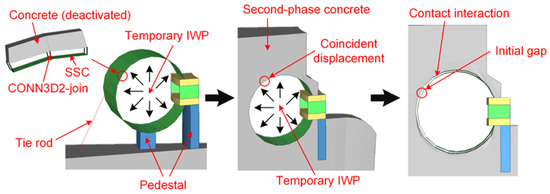
Figure 5.
The routine of the CSP (the initial gap between the concrete and the SSC has been exaggerated to better illustrate the procedure).
- (1)
- Deactivate second-phase concrete and specify temporary IWP in the SSC to simulate the pressurization of the SSC. With the existence of the connector elements, the inner surface of concrete expands with the SSC to maintain coincident displacement of the SSC and the concrete.
- (2)
- Activate second-phase concrete gradually to simulate its construction process.
- (3)
- After the set of second-phase concrete, deactivate the connector elements and activate the contact mechanism of the SSC and the concrete. Then, release the temporary IWP to simulate the formation of the initial gap between the SSC and the concrete.
- (4)
- Specify the operating IWP in the SSC step-by-step to simulate the operating condition of the SCS.
The reliability of CSP has been validated in multiple cases. In a 1/10 scale physical model test of a P-type SCS of the Pubugou HPP, the complex construction routine has been reproduced, and the results of the CSP agree well with the test at multiple key aspects, such as the gap and contact statuses, the stresses of steel materials, the displacement of generator pedestal and the cracks and damage values of concrete [20].
4. Results and Discussion
4.1. Initial Gap between the SSC and the Concrete
During the construction process, the initial gap between the SSC and the concrete comes into formation after the release of the temporary IWP. Under operating conditions, with the application of the operating IWP, the initial gap begins to close, and the SSC comes into contact with the concrete gradually. Accordingly, the initial gap should be a major factor that influences the SSC-concrete contact’s status, thus affecting the IWP-jointly-resisting status of SCS.
To better understand the relationship between the initial gap and the temporary IWP, five typical cross sections were taken for thorough comparison and analysis. As is shown in Figure 6, section 1 is at the inlet of the straight tube, and sections 2–5 are typical “C” cross sections of +X, −Y, −X and +Y coordinate axes, respectively. Considering the downstream narrowing of “C” cross sections, the structural analysis of SCS can be roughly considered as an axisymmetric problem, and the structural performance of each cross section is primarily influenced by spiral case’s radius and surrounding concrete’s size. Therefore, these chosen cross sections should well represent the overall situation [36].
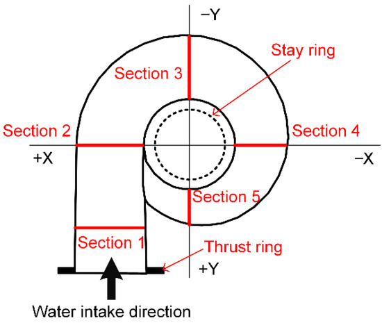
Figure 6.
Typical cross sections.
Figure 7 shows the calculated SSC-concrete initial gapping clearance at some representative points at five typical cross sections. An approximate linear relationship between the initial gapping clearance and the temporary IWP can be easily found in most curves, and it indicates that higher temporary IWPs directly lead to larger initial gaps. Moreover, significant unevenness in the distribution of the initial gap can be observed in all sections. In section 1, the gapping clearance at the left waist reaches 1.44 mm when the temporary IWP is chosen equal to the MDP at 6.86 MPa, while the gapping clearance at the right waist is only 0.09 mm at the same time. In sections 2–5, the gapping clearance at the left waist reaches 1.51 mm, 1.53 mm, 1.34 mm and 1.06 mm under the same condition above, respectively.
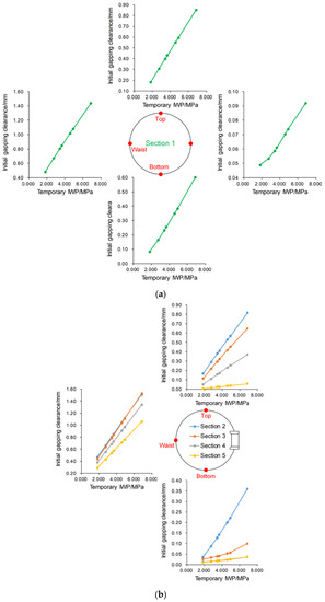
Figure 7.
Initial gapping clearance: (a) section 1; (b) sections 2–5.
As for the upper half of the SSC, the gapping clearance at the top of sections 1–5 reaches 0.85 mm, 0.82 mm, 0.65 mm, 0.37 mm and 0.06 mm with the temporary IWP at 6.86 MPa, respectively. Due to the gravity load of the structure, the initial gap tends to be closing at the lower half of the SSC, resulting in minimal gapping clearances at the bottom of all five cross sections.
This result may be explained by the irregular expansion mode of the SSC, as is shown in Figure 8. During pressurization, the stay ring remains fixed, while SSC expands radially under temporary IWP. Accordingly, the maximum initial gapping clearance always appears at the left waist of each cross section, and its value is obviously larger than that at the top and bottom.
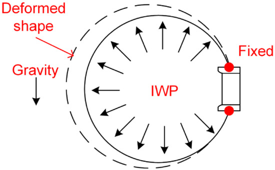
Figure 8.
Expansion mode of the SSC.
Another interesting aspect concerning the initial gapping clearance is that the value of the clearance decreases with the decrease in the radius of the cross section. Therefore, more attention should be paid to those cross sections with lager radii.
4.2. SSC-Concrete Contact Status
Under operating conditions, the SSC is specified with operating IWP, and the contact of the SSC and the concrete begins to close. In order to describe the contact-closing status briefly, the term contact-closing ratio is adopted in this study to quantitively describe the SSC-concrete contact’s status. The contact-closing ratio reveals the overall SSC-concrete contact status from a macro perspective. The contact-closing ratio is defined as follows:
where Sc is the contact-closing area obtained in the FE analysis; Sa is the entire contact area.
Figure 9 shows the evolution process of the contact-closing ratio of all seven cases. It is shown in the dotted curve that more than 13% of the SSC-concrete contact area remains open when the operating IWP reaches the temporary IWP, and the contact-closing ratio declines with the increase in temporary IWP.
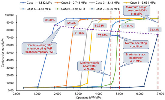
Figure 9.
The evolution process of contact-closing ratio.
The most striking result about case 7 is that only less than three-quarters of the SSC-concrete contact area is closed when the operating IWP reaches the temporary IWP, and Figure 10 shows the SSC-concrete contact status of it. Open status is mainly observed at the straight tube and the pedestal area of the SSC.
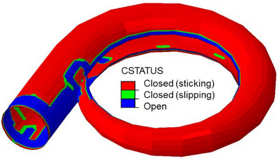
Figure 10.
SSC-concrete contact status of case 7 when the operating IWP reaches the temporary IWP.
Among all seven cases, cases 1–4 achieve an overall contact-closing status under normal operating condition. That is to say that, in this study, the temporary IWP should be no greater than 80% of the minimum static headwater to ensure the IWP-jointly-resisting status of the SSC and the concrete under normal operating condition.
In case 5, the contact-closing ratio reaches 78.67% at 4.58 MPa and increases to 91.07% at 4.91 MPa. While in case 6, the contact-closing ratio merely reaches 8.34% at 4.58 MPa, and reaches 78.00% at 4.91 MPa. In case 7, with the temporary IWP being chosen to be equal to MDP as 6.86 MPa, the SSC-concrete contact area basically remains open under normal operating conditions.
A marked observation to emerge from the results is that the SSC-concrete contact cannot restore the perfect contact-closing status even when the operating IWP is specified to be exactly equal to the temporary IWP. This should be attributed to the disaccord displacement of the SSC and the concrete.
In the design process, practitioners tend to design the structure under the assumed critical-loaded situation, which can be somewhat subjective. In this study, the SSC-concrete contact status varies greatly under different operating IWPs, and the assumed perfect contact-closing status never exists. It is erroneous to reckon that the temporary IWP can precisely offset part of the operating IWP, and the temporary IWP is never a strict threshold.
The operating IWP lies between the maximum and minimum static headwater under normal operating condition. Therefore, it’s significant to grasp the actual SSC-concrete contact status under normal operating condition.
When following European and Chinese design philosophies, an overall SSC-concrete contact closing status can be ensured under normal operating condition, and the structural integrity issue should not be a major concern. However, when following American design philosophy, the SSC-concrete contact is basically open under normal operating conditions. Even though this status is believed to benefit the stress condition of the concrete, it results in concern about the structural integrity and may cause structural vibration issues.
4.3. Stresses of the SSC and the Concrete
Figure 11 shows the circumferential stresses of the SSC and the concrete at some representative points at cross sections 1–3 (Figure 6) when the operating IWP is specified equal to the MDP (6.86 MPa). The dotted curves show the circumferential stresses of the SSC, and the solid curves show the circumferential stresses of the concrete.
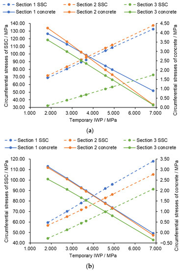
Figure 11.
Circumferential stresses of the SSC and the concrete at 6.86 MPa: (a) at the top; (b) at the waist.
In engineering practice, the SSC is designed to withstand the MDP independently with a conservative allowable stress intensity considered by reference to some design manuals or specifications [37,38]. While the current findings suggest that the concrete actually helps share part of the IWP, especially in the cases with lower temporary IWP. Therefore, the circumferential stress of the SSC is at a relatively low level, and the structural strength of the SSC should not be a major concern.
With the increase in temporary IWP, the circumferential stress of the concrete decreases, while the circumferential stress of SSC increases in an approximately linear pattern. When temporary IWP is specified to be equal to 40% of the minimum static headwater (1.832 MPa), the circumferential stress of concrete reaches 3.95 MPa, 4.25 MPa and 3.62 MPa at the top of sections 1–3. Since the characteristic value of the tensile strength of the concrete (C30-grade concrete in the Chinese grading system) is taken as 2.0 MPa in the CMWR design specification [39], the stress level of this case has already been far over the design code. When temporary IWP is specified to be equal to the MDP (6.86 MPa), the circumferential stress of concrete reaches 0.89 MPa, 0.15 MPa and 0.13 MPa at the top of sections 1–3, and no tensile stress is found at the waist of all cross sections.
Since this study mainly focuses on temporary IWP and its effect, the concrete is considered as linear-elastic. However, with the validated CSP, the results can well represent the IWP-jointly-resisting status, and the stress level of the concrete is quite informative.
A major idea of American design philosophy is to keep the stress of the concrete at a relatively low level, and it has been proven in this study. However, the results also reveal that the stress condition of the concrete under European and Chinese design philosophies is also acceptable, and the structural strength of the concrete can be ensured with the proper implantation of reinforced steel bars.
Moreover, the results also show that higher temporary IWP results in lower concrete stress, which indicates lower cracking risk of the concrete. This happens because higher temporary IWP results in lager initial gaps and tardier SSC-concrete contact closing, and the share of the IWP on the concrete is thus downgraded. However, considering the frequent start/stops needed for PSPPs and the relatively higher frequency of the pump turbine set, attention should be paid to the integrity and steady operation of the structure. Therefore, it is not necessary to specify the temporary IWPs equal to the MDP to avoid cracking risk, and the structure status under normal operating condition should be evaluated as well.
4.4. Share of Unbalanced Hydraulic Thrust
Apart from the issues mentioned above, the load-bearing characteristics of the unbalanced hydraulic thrust in SCS is also worth paying attention to. In China’s hydropower engineering practices, this issue has been observed in the feasibility study of M-type SCSs in the 700 MW class turbine unit [40,41]. However, it has long been neglected in P-type SCSs in PSPPs.
During the construction period of the SCS, the existence of the test head and other sealing devices makes the SSC a sealed pressure vessel. Therefore, the combined force of IWP in the SSC should be equal to zero. In operating period, after the removal of the sealing devices, the inlet of the SSC will be connected to an expansion joint or a penstock, and the former makes the inlet of the SSC a free-surface boundary. The SSC thus becomes an asymmetrical pressure vessel with an opening. Accordingly, the water flow in the SSC will generate an unbalanced hydraulic thrust in it. The value of the unbalanced hydraulic thrust is equal to the multiplication of the area of the inlet of the SSC and the operating IWP, and the direction of the thrust is downstream. Since the thrust forces the SSC to spin along the water flow, a thrust ring is normally set at the inlet of the SSC to help share that thrust and strengthen the connection of the SSC and the concrete.
As is shown in Figure 12, the unbalanced hydraulic thrust (F) is balanced with the test head in construction period, and it is shared jointly by the thrust ring (F1), the stay ring (F2) and the concrete (F3) in the operating period [40]. It is obvious that the share percentage of these three parts depends a lot on the IWP-jointly-resisting status.
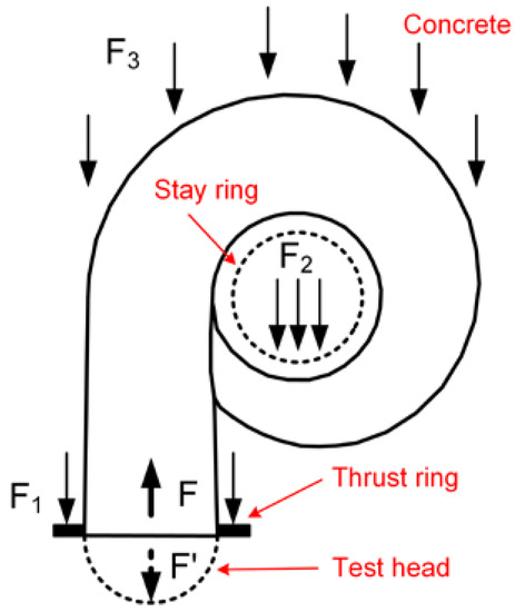
Figure 12.
Unbalanced hydraulic thrust.
Currently, the thrust ring is generally designed to share 100% of the unbalanced hydraulic thrust, and the stay ring is considered to be not involved in the share of the thrust [42]. This assumption simplifies the load-bearing characteristics of the unbalanced hydraulic thrust and is error-prone. Therefore, this subsection aims to study the effect of temporary IWP on the share of the unbalanced hydraulic thrust.
Figure 13 shows the share of unbalanced hydraulic thrust of the thrust ring, the stay ring and the concrete at 6.86 MPa. Under this condition, the value of unbalanced hydraulic thrust is 32.34 MN. It is shown that the share of unbalanced hydraulic thrust of the concrete declines with the increase in temporary IWP. Accordingly, the share of the thrust ring and the stay ring increases with the increase in temporary IWP. When the temporary IWP is specified equal to the MDP (6.86 MPa), the share of the thrust ring and the stay ring reaches 52.43% and 22.23%, respectively. The result proves the feasibility of the current design philosophy for the thrust ring.
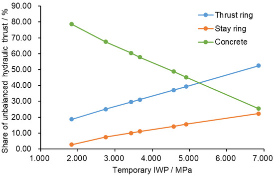
Figure 13.
Share of unbalanced hydraulic thrust at 6.86 MPa.
However, it is striking that the unbalanced thrust shared by the stay ring reaches 7.19 MN under this condition. That is to say that, contrary to common knowledge, the stay ring actually shares a certain part of the unbalanced hydraulic thrust, and it cannot be ignored. Accordingly, the reliability assessment of the connection between the stay ring and its supporting concrete is, thus, suggested for structural safety.
5. Conclusions
This study sets out to investigate the effect of temporary IWP on structural performance of SCS in PSPPs. It is crucial to note that the IWP-jointly-resisting status varies with different temporary IWP and operating IWP, and it fundamentally affects structural performance. The initial gap caused by the temporary IWP cannot be simply offset by the operating IWP, even when the operating IWP reaches the temporary IWP. In this study, the temporary IWP should be no greater than 80% of the minimum static headwater to ensure overall contact-closing under normal operating condition. It has been verified in this study that the stress condition of SSC should not be a major concern, and the circumferential stress of SSC increases with the increase in temporary IWP in an approximately linear pattern. The cracking risk of concrete is negatively correlated with temporary IWP, while it is not necessary to specify the temporary IWP equal to the MDP to avoid the risk. The share of unbalanced hydraulic thrust is found to be closely related to temporary IWP, and it cannot be ignored that the stay ring actually shares a certain part of it. The temporary IWP should be designed with an overall consideration of the IWP under normal operating conditions, the IWP-jointly-resisting status and design demands.
Moreover, with the exception for IWP, there are other factors that may affect the IWP-jointly-resisting status, including material deterioration, climatic conditions and vibration problems. A further study with more focus on the long-term performance of SCS affected by other factors is, therefore, suggested.
The limitation of this study might mainly lie in the idealized linear-elastic description of the concrete in FE analysis. Notwithstanding the limitation, the current study has made some profitable progress towards understanding the role of the temporary IWP, thus helping practitioners better fulfill their design demands.
Author Contributions
Formal analysis, X.G.; funding acquisition, H.W.; methodology, X.G. and D.F.; supervision, H.W. and D.F.; writing—original draft, X.G.; writing—review and editing, H.W. and D.F. All authors have read and agreed to the published version of the manuscript.
Funding
This research was funded by the National Natural Science Foundation of China, grant number 51679175.
Institutional Review Board Statement
Not applicable.
Informed Consent Statement
Not applicable.
Data Availability Statement
Not applicable.
Conflicts of Interest
The authors declare no conflict of interest.
References
- International Energy Agency. World Energy Outlook 2021; International Energy Agency: Paris, France, 2021; Available online: https://www.iea.org/topics/world-energy-outlook (accessed on 1 December 2021).
- International Hydropower Association. 2021 Hydropower Status Report, Sector Trends and Insights; International Hydropower Association: London, UK, 2021; Available online: https://www.hydropower.org/status-report (accessed on 1 December 2021).
- Frate, G.F.; Ferrari, L.; Desideri, U. Energy storage for grid-scale applications: Technology review and economic feasibility analysis. Renew. Energy 2021, 163, 1754–1772. [Google Scholar] [CrossRef]
- Sospiro, P.; Nibbi, L.; Liscio, M.C.; De Lucia, M. Cost–benefit analysis of pumped hydroelectricity storage investment in China. Energies 2021, 14, 8322. [Google Scholar] [CrossRef]
- Al-Addous, M.; Al Hmidan, S.; Jaradat, M.; Alasis, E.; Barbana, N. Potential and feasibility study of hybrid wind-hydroelectric power system with water-pumping storage: Jordan as a case study. Appl. Sci. 2020, 10, 3332. [Google Scholar] [CrossRef]
- Duan, L.; Wang, D.; Wang, G.; Han, C.; Zhang, W.; Liu, X.; Wang, C.; Che, Z.; Chen, C. Piecewise Causality Study between Power Load and Vibration in Hydro-Turbine Generator Unit for a Low-Carbon Era. Energies 2022, 15, 1207. [Google Scholar] [CrossRef]
- Wang, L.; Zhang, K.; Zhao, W. Nonlinear Modeling of Dynamic Characteristics of Pump-Turbine. Energies 2022, 15, 297. [Google Scholar] [CrossRef]
- Lu, J.; Hu, Q.; Gu, Z.; Zheng, K.; Meng, X.; Yi, Z. Rotor-Stator Interaction and Solutions of Pump-turbine in ZHANGHEWAN Pumped-storage Power Station. Hydropower Pumped Storage 2019, 5, 82–86. (In Chinese) [Google Scholar] [CrossRef]
- Donalek, P.J. Pumped Storage Hydro: Then and Now. IEEE Power Energy Mag. 2020, 18, 49–57. [Google Scholar] [CrossRef]
- Wu, H.; Gao, X.; Fu, D. Review and prospect in research and application of spiral case structure in hydropower plant. Shuili Xuebao/J. Hydraul. Eng. 2021, 52, 770–780. (In Chinese) [Google Scholar] [CrossRef]
- Zhang, Q.L.; Wu, H.G. Embedment of steel spiral cases in concrete: China’s experience. Renew. Sustain. Energy Rev. 2017, 72, 1271–1281. [Google Scholar] [CrossRef]
- Yuan, S.; Fang, Y.; Yuan, J.; Zhang, J. Review on vibration problems of power units in commissioned pumped storage projects in China. Shuili Fadian Xuebao/J. Hydroelectr. Eng. 2015, 34, 1–15. (In Chinese) [Google Scholar] [CrossRef]
- Wu, H.; Shen, Y.; Jiang, K. Structural research on embedment of a bare deflated spiral case. Wuhan Univ. J. Nat. Sci. 2007, 12, 311–316. [Google Scholar] [CrossRef]
- Tian, Z.; Zhang, Y.; Ma, Z.; Chen, J. Effect of concrete cracks on dynamic characteristics of powerhouse for giant-scale hydrostation. Trans. Tianjin Univ. 2008, 14, 307–312. [Google Scholar] [CrossRef]
- Wu, H.; Shen, Y.; Jiang, K.; Shi, J. Structural Analysis of the Embedded Spiral Case in the Three Gorges Hydropower Station. Pract. Period. Struct. Des. Constr. 2012, 17, 41–47. [Google Scholar] [CrossRef]
- Xu, X.; Li, M.; Ma, Z.; Zhang, H.; He, P. Simulation and analysis of the constant internal pressure spiral case with non-uniform gap. Shuili Fadian Xuebao/J. Hydroelectr. Eng. 2009, 28, 75–80. (In Chinese) [Google Scholar]
- Zhang, Q.; Wu, H.; Yang, H. Effect of modeling range on structural analysis for powerhouse of hydroelectric power plant by FEM. Trans. Tianjin Univ. 2009, 15, 388–392. [Google Scholar] [CrossRef]
- Guo, T.; Zhang, L.; Li, S. Influences of boundary conditions on the initial gap of preloading water-filled spiral case. Trans. Chin. Soc. Agric. Eng. 2020, 36, 40–47. (In Chinese) [Google Scholar] [CrossRef]
- Guo, T.; Zhang, L.; Li, S. Research on three-dimensional simulation algorithm of preloaded filling spiral case with non-uniform gap. Shuili Xuebao/J. Hydraul. Eng. 2015, 46, 1434–1443. (In Chinese) [Google Scholar] [CrossRef]
- Zhang, Z.; Wu, H.; Shi, C.; Zhang, Q.; Su, K.; Hu, L. Numerical modeling of preloaded filling spiral case structure. Lat. Am. J. Solids Struct. 2018, 15, 1–20. [Google Scholar] [CrossRef]
- Ma, Z.; Zhang, C. Static and dynamic damage analysis of mass concrete in hydropower house of Three Gorges Project. Trans. Tianjin Univ. 2010, 16, 433–440. [Google Scholar] [CrossRef]
- Wei, S.H.; Zhang, L.J. Vibration analysis of hydropower house based on fluid-structure coupling numerical method. Water Sci. Eng. 2010, 3, 75–84. [Google Scholar] [CrossRef]
- Cui, H.; Zhang, D.; Shi, B.; Peng, S. BOTDA based water-filling and preloading test of spiral case structure. Smart Struct. Syst. 2018, 21, 27–35. [Google Scholar] [CrossRef]
- Zhang, Q.L.; Hu, L.; Hu, C.; Wu, H.G. Low-cycle fatigue issue of steel spiral cases in pumped-storage power plants under China’s and US’s design philosophies: A comparative numerical case study. Int. J. Press. Vessel. Pip. 2019, 172, 134–144. [Google Scholar] [CrossRef]
- Zhang, Z. Force-Transferring Mechanism of Spiral Case and Characteristics of Flow-induced Vibration of Powerhouse in Hydropower Station. Ph.D. Thesis, Wuhan University, Wuhan, China, 2019. (In Chinese). [Google Scholar]
- Guo, T.; Zhang, L.; Wu, L. Advance in Research and Application of Preload Filling Spiral Case Structure in Hydroelectric Power Plant. J. Kunming Univ. Sci. Technol. Nat. Sci. 2015, 40, 70–78. (In Chinese) [Google Scholar] [CrossRef]
- Guo, T.; Zhang, L.; Zhou, J.; Bai, B.; Liu, X. Simulation of preloading water-filled spiral case structure with weak simulation algorithm. Procedia Eng. 2012, 31, 492–496. [Google Scholar] [CrossRef][Green Version]
- Xu, X.; Ma, Z.; Zhang, H. Simulation algorithm for spiral case structure in hydropower station. Water Sci. Eng. 2013, 6, 230–240. [Google Scholar] [CrossRef]
- U.S. Army Corps of Engineers. EM 1110-2-3001 Planning and Design of Hydroelectric Power Plant Structures; Department of the Army: Washington, DC, USA, 1995.
- China’s Ministry of Water Resources. SL 266-2014 Design Code for Hydropower House; China Water Power Press: Beijing, China, 2014. (In Chinese)
- Rabbat, B.G.; Russell, H.G. Friction Coefficient of Steel on Concrete or Grout. J. Struct. Eng. 1985, 111, 505–515. [Google Scholar] [CrossRef]
- Baltay, P.; Gjelsvik, A. Coefficient of Friction for Steel on Concrete at High Normal Stress. J. Mater. Civ. Eng. 1990, 2, 46–49. [Google Scholar] [CrossRef]
- Hu, L.; Zhang, Q.-L.; Shi, C.-Z.; Wu, H.-G. Hydraulic load-bearing mechanism in rib-strengthened steel bifurcation structures of hydroelectric power plants: Numerical simulation. Mech. Based Des. Struct. Mach. 2021, 49, 1–17. [Google Scholar] [CrossRef]
- Zhang, C.H.; Zhang, Y.L.; Ma, Z.Y. Damage analysis of reinforced concrete surrounding the spiral case under the action of repeated water pressure. Shuili Xuebao/J. Hydraul. Eng. 2008, 39, 1262–1266. (In Chinese) [Google Scholar] [CrossRef]
- ABAQUS. Abaqus Analysis User’s Manual; Abaqus 6.1; Dassault Systèmes Simulia Corp.: Providence, RI, USA, 2012. [Google Scholar]
- Zhang, Q.L.; Wu, H.G. Effect of compressible membrane’s nonlinear stress-strain behavior on spiral case structure. Struct. Eng. Mech. 2012, 42, 73–93. [Google Scholar] [CrossRef]
- American Society of Civil Engineers. ASCE Manuals and Reports on Engineering Practice No.79 Steel Penstocks, 2nd ed.; American Society of Civil Engineers: Reston, VA, USA, 2012. [Google Scholar]
- China’s Ministry of Water Resources. SL 281-2003 Design Specification for Steel Penstocks of Hydroelectric Stations; China Water Power Press: Beijing, China, 2003. (In Chinese)
- China’s Ministry of Water Resources. SL 191-2008 Design Code for Hydraulic Concrete Structures; China Water Power Press: Beijing, China, 2008. (In Chinese)
- Fu, D. Study on Structural Characteristics and Earthquake-Resistance of Powerhouse at Dam Toe Considering Powerhouse and Dam Interaction. Ph.D. Thesis, Wuhan University, Wuhan, China, 2015. (In Chinese). [Google Scholar]
- Fu, D.; Wu, H.; Hu, L.; Li, H. Study on transfer mechanism of stay ring forces of spiral case with cushion layer in hydropower station. J. Hydroelectr. Eng. 2014, 33, 196–201. (In Chinese) [Google Scholar]
- Wei, L. Design of Draft Tube of Huilong Pump Turbine. Power Syst. Eng. 2008, 24, 55–56. (In Chinese) [Google Scholar]
Publisher’s Note: MDPI stays neutral with regard to jurisdictional claims in published maps and institutional affiliations. |
© 2022 by the authors. Licensee MDPI, Basel, Switzerland. This article is an open access article distributed under the terms and conditions of the Creative Commons Attribution (CC BY) license (https://creativecommons.org/licenses/by/4.0/).