1. Introduction
The Internet of Energy (IoE) is the deployment of IoT technology within energy systems (including distributed power monitoring and measuring points, energy plant sensors, points of distribution) to increase the efficiency of the whole infrastructure while decreasing the energy waste [
1,
2]. A similar term to the IoE is the Energy Cloud, however Energy Cloud refers to a common integration platform for handling and processing data from all the applications related to energy management [
3,
4]. Such a platform will be in the cloud and, partially, in the edge, whereas the IoE refers to the use of one underlying communication network for connecting the devices of the energy-power distribution infrastructure, regardless of how (and where) the data are processed.
The IoE assumes a high number of sensors that send/receive Mobile Autonomous Reporting (MAR) exception reports (around 20 bytes/message with interarrival of around several days), Mobile Autonomous Reporting periodic reports (around 20–200 bytes/message with interarrival of once per two hours), Network originated reports (around 20–200 bytes/message with interarrival of once per two hours) and Software update/reconfiguration model (around 2 kbytes/update and two updates/year). IoE also assumes other kinds of applications, such as video surveillance, which requires high bitrates and many critical applications that need a short response time.
The success of IoE depends on many factors, including the increase in applications that can be used to control the power supply chain, the reduction in the costs of the sensors, especially the reduction in the costs of the network infrastructure, while keeping the requirements that IoE poses to the network, in addition to higher flexibility in the network, so that different scenarios may be considered.
From the point of view of sensors, IoT is moving ahead very fast with the appearance of many new applications, but also with the appearance of always cheaper solutions based on Software Defined Radio (SDR), which is an approach to the implementation of radio communications based on deploying typical radio modules (modulation, filtering, multiplex, etc.) as software, so that it is possible to avoid all the inconveniences of the hardware due to limitations of electronics. Commonly, SDR maintains only Digital-to-Analog and Analog-to-Digital converters and antennas as hardware. SDR makes feasible the relatively low-cost implementation of end devices even in advanced technology as 5G [
5], which fulfils one of the prerogatives of IoE over 5G.
From the point of view of the network, IoE poses strong requirements to the infrastructure, not only related to radio interface but also related to the deployment of the network. Since the energy systems are critical systems, the network developed for IoE should typically use separate radio resources. This means that in almost all countries, a separate frequency band is reserved for energy companies; however, this does not necessarily imply that the whole network infrastructure will be separate from a public network. While the radio network should be separate for IoE, the core network may be separate or may be common with public networks. The main criteria for selecting any of the options are costs, security assurance level of the core and management accountability (i.e., whether the energy company can manage the communication network, or it must rely on an external telco operator). As far as the radio network is concerned, there are several criteria that should be afforded to decide the radiocommunication technology to be used. The most important criteria are the needs of wide coverage, cost-saving (in both, money expenses and energy usage) and security assessment (including confidentiality, integrity, and availability) such as the implementation of Security Incident and Event Management (SIEM) and Security Orchestration, Automation and Response (SOAR) systems, as well as the implementation of continuous integration/continuous deployment (CI/CD) of the network elements (generally, the Network Functions) [
6].
In this paper, we focus on the requirements and potential solutions (implementations) of the underlying communication network that provides connectivity to IoE systems. This communication network will be deployed in all the physical infrastructures of the energy company. For example, with the radio resources (frequency) reserved for the energy companies, this will interconnect all sensors in a power plant but also will connect management hubs through the whole energy distribution infrastructure. All the hubs and points of presence may be connected by one common radio technology that uses a separate frequency. We analyse the advancements of the 5G radio technology and show that 5G is the most suitable communication technology for IoE, since it fulfils the requirements related to critical applications and massive data treatment. This is discussed in
Section 2. In
Section 3, we present an efficient and cost-saving implementation of the 5G based on Open RAN (Open Radio Access Network) concept. The reasoning for using Open RAN is that it will be possibly cheaper (thanks to increased concurrency) and more flexible for specific requirements that the IoE may pose. The biggest issue for deploying Open RAN in the IoE is the limitations of the Open RAN technology, especially in the use of beamforming technique since Open RAN has not yet implemented an effective coding scheme through the different Open RAN modules. Therefore, the research effort of this paper goes in the direction of solving the lack of beamforming deployment in Open RAN by introducing an adapted equalization algorithm. The model of the equalization and the results are presented in
Section 4. The results show the gaining of the proposed equalization algorithm in comparison to other algorithms. At last,
Section 5 concludes that by solving beamforming, Open RAN may be the solution for a cost-saving and efficient 5G technology for the IoE.
2. 5G as the Network of the IoE
IoE imposes several requirements on the underlying infrastructure that are related to the applications and services needed in the energy sector and their high standards in regard to privacy and security. In addition, critical Machine-to-Machine (M2M) services require a quick response from the network. Therefore, IoE needs a flexible, secure network with high capacity and wide radio coverage. The mobile networks fulfil some of those requirements, however, until the fifth generation of mobile networks (5G), they were not very flexible. The typical characteristics of the 5G make feasible its use as IoE underlying network. The high capacity 5G features are described below, together with the technologies adopted by 5G to achieve such a high capacity.
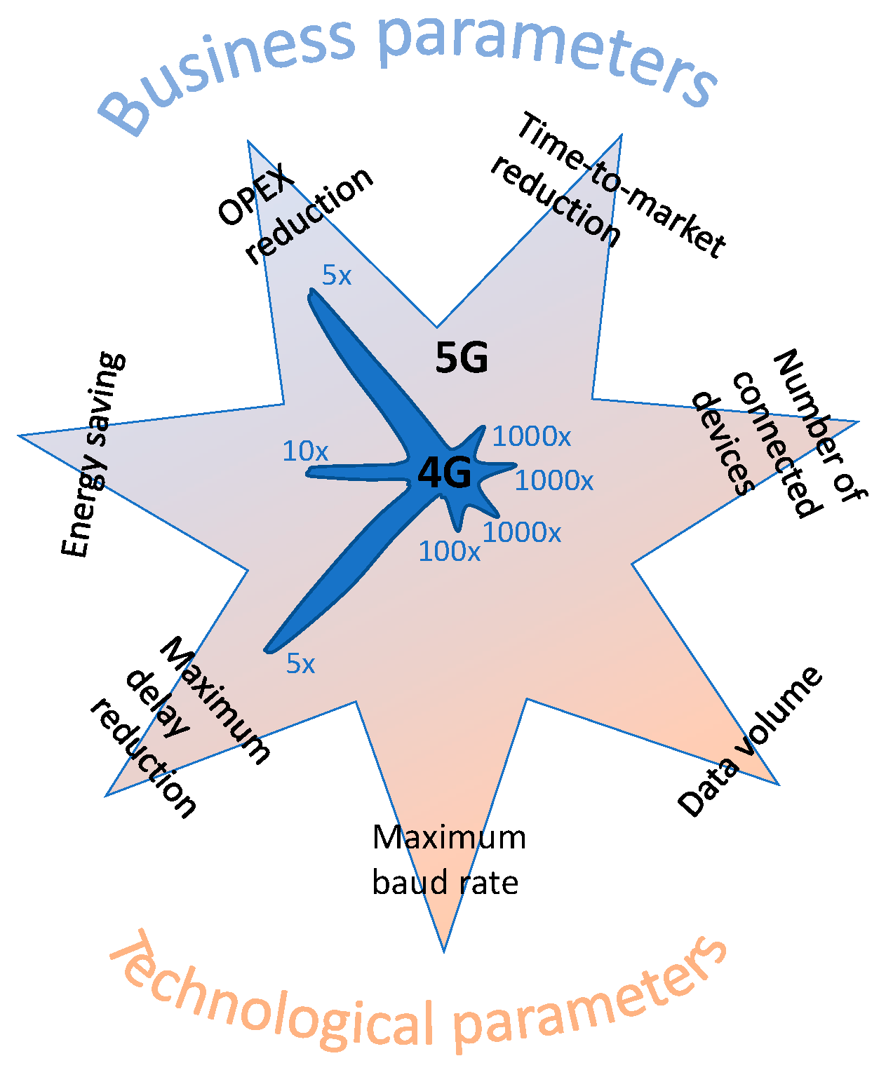
The requirements for 5G networks can be divided into business and technological requirements.
Figure 1 shows the requirements of 5G in comparison to 4G [
7].
Concretely, the requirements for the 5G network in comparison to the previous generation of mobile networks are:
1000-fold increase in the value of the data volume (≥10 Tb/s/km2),
100-fold increase in the value of the maximum baud rate (≥10 Gb/s),
1000-fold increase in the number of connected devices (≥1 M devices/km2),
10-fold (1/10)—decrease in energy consumption by the device, compared to 2010,
5-fold (1/5) reduction of the current delay value (≤1 ms for some applications),
5-fold decrease (1/5) in network operating costs—OPEX,
1000-fold reduction (1/1000) of the current time of service implementation (≤90 min).
These requirements can only be met if the network introduces many new mechanisms, not all of which are closely related to telecommunications (e.g., new solutions from energy suppliers that will significantly reduce energy consumption).
1000-fold increase in the value of the data volume (≥10 Tb/s/km2), and 100-fold increase in the value of the maximum baud rate (≥10 Gb/s):
The first two requirements are related to the much higher bitrate required in 5G networks compared to previous mobile networks. Higher bit rates can be achieved in radio access due to increased link capacity, higher bandwidth efficiency (b/s/Hz), and higher cell density. All three of these elements were provided for in 5G. The most immediate way to achieve a high bit rate is to increase the available bandwidth. 5G is planned to operate in a wider range of bands than 4G. Standards [
8,
9] specify the frequency ranges in which the New Radio (NR) is to operate. In general, two broad bands have been identified, denoted as FR1 (450 MHz to 6 GHz) and FR2 (24.25 GHz to 52.6 GHz). The first range describes 30 bands of operation (denominated from n1 to n86) operating in both frequency duplex (FDD) and time duplex (TDD) mode and unidirectional “downstream” (SDL) and “upstream” (SUL). In turn, the bands intended for use in the FR2 are 26,500 MHz–29,500 MHz, 24,250 MHz–27,500 MHz, and 37,000 MHz–40,000 MHz. These bands are intended for transmission in TDD mode. It should be noted that the FR2 range is millimetre waves, which have not been used in cellular systems so far (except in radio lines), and the use of which presents a great technological challenge. Millimetre-wave signal propagation often requires direct visibility of the antennas because buildings and vegetation significantly attenuate signals in these frequency ranges. It can be shown that the range in a densely urbanized environment is of the order of 150–200 m.
In line with these recommendations, three frequency bands are typically used for the new network:
(1) The 700 MHz band will be used to ensure trouble-free coverage over large areas. One of the subsystems that can expect benefits from the use of new, reserved bandwidth seems to be intelligent agriculture.
(2) The 3.4–3.8 GHz band will be the basic band used by most applications (typical applications taken over from 4G will be implemented in it). The standard provides for the application of the so-called carrier aggregation, whereby the individual channel bands are combined and made available to specific connections. This aggregation applies to both adjacent and non-adjacent channels on the frequency axis (ranges used for other purposes will be between the individual fragments of the band used).
(3) The 26 GHz band will be used in microcells. The range of the signal in this band is much smaller than in the case of the lower bands, which will require a large number of (micro) antennas to cover a given area. This band will be used in hotspot areas for enhanced Mobile Broadband (eMBB) and, in some cases, for Ultra-Reliable Low-Latency Communications (URLLC).
In addition to the bands mentioned, there is a clear tendency to reserve also other frequency ranges for specific applications. For example, the automotive industry is seeking to reserve the 5.9 GHz band for communication with vehicles. Additionally, energy supply operators reserve bands in lower frequency ranges in order to increase the coverage and availability of the operator-managed telecommunications network (including M2M communication). In this band, IoE will be developed based on 5G technologies while using the reserved licensed bandwidth in parallel with typical 5G access, as for example in private networks [
10].
An effective approach to increasing the bit rate is to improve spectral efficiency. This is achieved in 5G by introducing the concept of multi-antennas—massive Multiple-Input Multiple-Output (commonly known as the massive multi-antenna technique—massive MIMO), which allows the transmission and reception of multiple signals simultaneously on the same radio channel. Massive MIMO can significantly increase the capacity of a wireless system without the need to broaden the spectrum (some tests indicate up to a 50-fold increase in bit rate compared to a single input signal and a single antenna). The MIMO multi-antenna technique assumes a massive (more precisely, very large) number of antennas in the base station and several antennas in the subscriber’s devices. The massive MIMO technique is an extremely interesting field of research and since the first publications, it has already had many studies. This technique, thanks to the use of antenna arrays, allows for efficient three-dimensional shaping of radiation beams to many UE stations, simultaneously contributing to increasing the range, energy efficiency (through beamforming), and at the same time reducing the inter-user interference. Hardware implementations already include 256 × 256 (256 Uplink, 256 Downlink) antennas, and more, with larger dimensions, are planned for implementation. Massive MIMO can support multiple devices within one hotspot while maintaining high data rates.
At the same time, it should be emphasized that the use of massive MIMO transmission creates serious technological challenges due to the large size of antenna arrays, and, thus, high hardware complexity of the implementation of such matrices and large dimensions of digital signal processing algorithms that must be implemented in real-time. The energy requirements related to, e.g., the implementation of digital-to-analogue and analogue-to-digital converters and the use of a large number of amplifiers. Moreover, massive MIMO requires the resolution of important security issues due to the risks associated with disruptions [
11].
Other mechanisms that increase the efficiency of 5G systems include, among others, new methods of managing disruptions, such as the mechanisms based on radio access scheduling, as proposed by Woosek et al. in [
12]. Of course, any radio access schedule introduces an additional delay and can limit reliable communication with the low latency required. Therefore, the use of interference management mechanisms to control access to the medium to avoid inter-channel interference should exclude critical 5G usage scenarios, also in IoE.
Another, third way to increase the capacity (and transmission rate) is to increase the cell density, thanks to the installation of many microcells (and even picocells in a millimetre-wave band). By reducing the size of the cells, the number of users served in a given band is reduced, which allows for an increase in the capacity per user. The downside of this is the potential increase in interference, however, this problem is addressed by the control and selection of frequencies used at the cell boundary; neighbouring cells do not use the same bandwidth for users located near the cell boundary. Other disadvantages of microcells (or at least challenges) include frequent (potentially) switching connections (to ensure their continuity), the inability to provide MIMO techniques in such reduced areas, and the need to provide distributed access to radio in the cloud.
Another solution that allows handling the increased traffic exchanged inside the cell is to use direct transmission between devices (D2D—Device-to-Device), in particular concerning connections between terminals that are in close proximity to each other. This will allow the traffic load of the base station to be reduced, at least during the information exchange phase, after the connection is established. D2D is one of the options to improve coverage while reducing the needed power of the transmitted signal.
1000-fold increase in the number of connected devices (≥1 M devices/km2):
The number of devices that use connectivity offered by cellular networks has grown exponentially in recent years. The technological advances that caused this growth have been the development of mainly “narrowband” technologies. Until recently, IoT used other short-range (and medium) wireless technologies, such as Bluetooth, ZigBee, Wi-Fi, or LoRa, as it was not possible to use cellular networks, such as LTE/LTE-Advanced due to the relatively high price of calls in these networks. In the case of a narrowband service, the connection price drops sharply at the expense of increased latency. However, higher latency is accepted by most IoT applications. The project of a narrowband IoT network implemented within LTE, called NB-IoT, takes into account the unique M2M type communication for devices with low volume and low required data transfer speed (up to 200 kbps) and low mobility (it is assumed that IoT devices using NB-IoT are mostly stationary). The NB-IoT standard also provides connection switching, however, mobility management and IoT communication interruptions cause significant energy consumption.
The main advantage of NB-IoT is the considerable range compared to short-range wireless technologies, and the low cost and low power consumption compared to LTE. The advantages of NB-IoT in IoT connections also relate to the significant improvement in security. As is known, mobile networks guarantee secure communication based on shared keys (operator’s equipment and infrastructure) for authentication and authorization, and the communication is encrypted between the terminal and the base station. Moreover, such communication is more reliable because NB-IoT uses a licensed bandwidth, which limits the amount of interference.
In 5G networks, narrowband connectivity will be improved, particularly concerning energy-saving functions. Battery life in IoT devices will reach 20 years. Mechanisms such as sleep mode (the device is in a very low power state when it is not sending data) and discontinuous reception (the device can only receive data at certain times) will be enhanced in 5G (Release 17 is expected at the middle of 2022).
Another aspect of note is that massive Machine Type Communication (mMTC) may or may not be tightly linked to the 5G network; this will be ensured by improved public/subscribe platforms. The p/s concept is a solution implemented with a higher layer in the IoT architecture and is based on the subscription of IoT devices within a wider platform so that all communication with the device passes through the given platform. In this way, any other machine trying to obtain information from the device should connect to the platform and ask for information. The p/s technique solves the problem of the lack of addresses on the Internet (devices do not have public addresses), which somewhat inhibits the development of IPv6 (the main function of IPv6 is no longer needed). Web of Things (WoT) combines the management of smart devices and IoT data access and activation via web services. This solution uses popular protocols and well-known web patterns to build the Internet of Things that is interoperable, easy to program, and intuitive to use, e.g., [
13].
10-fold (1/10)—decrease in energy consumption by the device, compared to 2010:
In recent years, there have been many successes in the field of material technologies, allowing a reduction in energy consumption for all devices. This applies, inter alia, to new batteries with long life and renewable energy sources, which are also becoming more and more popular in telecommunications.
From a network communication perspective, there are also many other ways to reduce 5G power consumption [
14]. In addition to the narrowband technology which greatly reduces the power consumption of IoT devices as explained above, there are also other mechanisms introduced in 5G that are energy efficient.
One of the most important is the introduction of the beamforming technique, thanks to which the shaped radio signal is sent to strictly defined users. With beamforming, multiple antennas can also be used to direct signals to reduce physical areas, whereby the system performance is multiplied by being able to serve multiple users on the same band. Beamforming increases the number of users served on the same frequency, but it does not increase the efficiency itself. However, the main characteristic of beamforming is the reduction of the signal power needed in communication thanks to the punctual shape of the beam created by the antenna array. At the receiver side, the multiple antennas receiving the signal may increase the signal-to-noise ratio in comparison to a single antenna, so for a given level of noise, lower signal power is needed for the proper transmission of information. The beamforming technique is always implemented together with massive MIMO because the principle of operation is the same (multiple antennas) [
15].
Other mechanisms that reduce energy consumption in the network are related to transmission systems and channel access management. New transmission systems such as Multi-Carrier Filter-Bank (FBMC), Universal Filtered Multi-Carrier (UFMC), and Generalized Frequency-Division Multiplexing (GFDM) have been designed for 5G to reduce timing requirements; however, they are not sufficiently mature for being deployed in current 5G implementations. Synchronization usually requires extensive and therefore energy-consuming signalling procedures between the cell phone (or mobile device) and the antenna. By reducing the synchronization overhead, the mobile phone may be idle for a longer time. Additionally, access to the orthogonal channel, along with Orthogonal Frequency-Division Multiplexing (OFDM), crucial for LTE technology, introduces additional signalling, which reduces the battery life of mobile devices. Because of this, 5G has proposed (but not yet deployed) non-orthogonal channel access methods for uplink communication (from cell phone to antenna). Access to the non-orthogonal channel is however less efficient (less bandwidth efficient), which makes this type of access (non-orthogonal) not proposed for downlink communication. Non-Orthogonal Multiple Access (NOMA) consists of using the same time and frequency resources several times to make connections between base stations and properly selected terminals, which differ significantly in the power level of transmitted signals. This allows the effective application of signal compensation in receivers. So far, NOMA has not been standardized to be applied in 5G systems. Works on NOMA will be continued in the development of 6G systems. Other mechanisms, which are being investigated, are related to mobile network management and, concretely, with the introduction of machine learning mechanisms in 5G with heterogeneous access technologies [
16].
5-fold (1/5) reduction of the current delay value (≤ 1 ms for some applications):
Reducing the latency in network access was and is one of the most difficult parameters to achieve in a mobile network, and at the same time one of the most promising. Several new services are expected to take advantage of this important network feature to deliver mission-critical applications in the IoE. The network changes required to ensure an end-to-end delay of 1 ms are numerous. Transmission delay should be minimized, radio access should be faster with limited signalling overhead, applications should be served as close to users as possible and data pre-processing should be performed at the edge of the network instead of in a remote computing cloud, etc. However, one of the most important new technologies for reducing latency is Multi-access Edge Computing (MEC), a concept related to placing computing servers close to radio access points. The MEC technology thus extends the concept of cloud computing by transferring delay-sensitive application components from distant data centres to computing servers located at the edge of the network, i.e., in the environment of consumers and data generated by applications. MEC can also contribute to a revolution in network management.
5-fold decrease (1/5) in network operating costs—OPEX, and 1000-fold reduction (1/1000) of the current time of service implementation (≤90 min):
Both of the above requirements for 5G networks, even if they are not closely related to technology, have a large impact on its implementation. Both requirements are related to the fact that 5G is a business network, and in business, money and time are crucial. From a technological point of view, there are new developments that make 5G meet these two requirements. The most important things here are virtualization and software network solutions. Virtualization ensures the separation of services and applications, which in turn accelerates the implementation of new services on the network. Software solutions (implementing many network services independent of hardware requirements) significantly reduce costs and make the network easier and faster adapted to new services (high flexibility).
The Network Functions Virtualization (NFV) solution enables the creation of virtual networks in a software manner [
17,
18]. This solution uses distributed computing infrastructure (distributed data centres) to dynamically install such networks. Virtual networks are created based on previously prepared templates (blueprints), which contain a set of virtual network functions, their configuration data, as well as connections between them (network topology).
To fulfil the above requirements, the network needs to be very flexible and capable of handling different scenarios. In the case of the IoE, the potential scenarios are from energy plants, where a narrow-coverage but high-capacity network is needed until the wide network for sensor information, and in all scenarios, critical and non-critical applications should be possible. The 5G has adopted virtualization and almost full softwarization; thanks to that, the network operator may separate duplicates and manage the network functions dynamically. For example, in the case of an energy plant with a high amount of data to be processed in a short time, the operator could decide to dedicate some processor power near to the tower where the data are stored, or even it is possible to locate jointly to the Radio Access Network some network functions of the Core Network such as the User Plane Function, which is in charge of forwarding data messages. This way, the packets could be processed in a data centre located in the same energy plant. In order to dynamically commission and activate one function, the software (network function) is containerized in one instance (the hypervisor of a system-level virtualization platform is responsible for operating different instances developed on one common-to-all-instances Operating System to work simultaneously on a single server).
Even if the 5G has achieved high flexibility and high technical capacities, a specific implementation such as IoE could require specific functions to be executed in the network, and this may require the Network Equipment Supplier to deploy such energy sector-specific functions. For this scope, the operators could develop the network based on the Open RAN (Radio Access Network) approach. Open RAN consists of defining high (higher than 5G standardization) interfaces in the radio part of the network so that the elements can be separated and interconnected through well-defined interfaces. The scope of the Open RAN model is that smaller elements can be deployed separately, by different vendors. This increases the concurrence and flexibility (for example, one vendor could specialize in some functionalities for the energy sector). In the next section, we present Open RAN as one of the keys for the deployment of the network addressed to the implementation of IoE.
3. Open RAN for Flexible Development of 5G Networks
In the classical vision of the development of mobile networks, the individual RAN elements are practically always provided by one supplier because the interfaces between them are largely closed proprietary solutions. As a result, the selected supplier carries out orders (from Mobile Network Operator, MNO) for base stations for a given area, which is commonly known as a cluster. This situation is given by the limited standardization offered by 3GPP, which reduces the interoperability of multi-vendor elements of the network. Thus, operators identify obstacles to the development of new services due to the lack of flexible and agile development of their networks. In Open RAN networks, the flexibility is higher since more providers may develop concrete solutions requested by the customers of the network. Under the presented conditions, maintaining the so-called multi-vendor, although possible in some situations, is extremely difficult to maintain and manage.
Another aspect that prompts telecommunications operators to deal with Open RAN is the issue of the costs of building a 5G network. Disaggregation of the network (Open RAN) could reduce costs, since more actors could provide network equipment (especially in the case of software) and more innovation could develop better management [
19].
Flexibility and cost-saving are both crucial for the development of the IoE, therefore we think that Open RAN may be a way for developing IoE with 5G technology.
Open RAN architecture is based on new open interfaces (standardized mainly by O-RAN Alliance and its predecessors) which are added to the 3GPP-standardised F1 interface. 3GPP considers that Radio Access Network may be divided into two main components: Centralized Unit and Distributed Unit. 3GPP standardize the interface between the two units (F1 interface). The two units perform concrete radio functionalities: the ones that may be carried out far away from the antennas and are common to a number of antennas are performed by the Centralized Unit, whereas the functionalities that must be run close to the antenna are performed by the Distributed Unit.
The Centralized Unit runs: (1) the Radio Resource Control (RRC) protocol, which is in charge of broadcasting the system information, establishment and maintenance of the RRC connections (carrier aggregation, Dual Connectivity), managing security keys with the Core Network, configuring Signalling and Data Radio Bearers, managing handover and interRAT mobility, reporting User Equipment (UE) measurements, and transferring to the Core the NAS (Non-Access Stratum) messages; (2) the Service Data Adaptation Protocol (SDAP), which is responsible of handling QoS (Quality of Service) established by the Session Management Function in the Core, including Guaranteed and Non-guaranteed bit rates as well as negotiated or reflective QoS in the Uplink, executing the radio bearers configured by the RRC and the PDU sessions (each session requires one SDAP instance); (3) the Packet Data Convergence Protocol (PDCP), which performs the next functionalities: transfer of data including sequence numbering and handover control, TCP/IP header compression, ciphering/deciphering and data protection, discarding of Signalling Data Units, managing dual connectivity of Packet Data Units and selection of the Transparent, Acknowledged and Unacknowledged modes of the Radio Link Control [
20,
21,
22,
23].
The Distributed Unit runs: (1) Radio Link Control (RLC) protocol, which is in charge of handling transparent, acknowledged, or unacknowledged modes of transmission between the radio and the UE, i.e., how the packet transmission in the radio interface should be acknowledged including the transparent mode for synchronization and other system messages that pass directly to the antenna without further processing in the RLC. Message segmentation, packet sequence, and segment offset are also handled by this protocol; (2) the Medium Access Control (MAC) protocol, which is responsible for the functioning of the transport channels including multiplex/demultiplex, in-band monitoring, error acknowledgment, and error coding (HARQ mechanism), prioritization and random access procedures, including contention-based random access or contention-free random access; and (3) physical layer, which converts the information in electrical signal modulated by the sub-carrier [
21,
23,
24,
25].
In addition to F1, Open RAN architecture defines another interface on the side of the Distributed Unit. The 7-2x split variant separates the lower Physical Layer baseband processing and radio frequency front-end from the other functionalities of the Distributed Unit. Physical baseband and radio front-end are carried out in the so-called Open Radio Unit (O-RU), whereas the other functions are carried out in the Open Distributed Unit (O-DU). There are two categories of O-RU: A and B. In O-RU category A, the pre-coding tasks are not carried out in the O-RU and they are executed by the O-DU. In this case, pre-coding is separate from Cyclic-prefix control, Fourier conversion (Fast-Fourier Transform), and beamforming. The advantage, in this case, is that the O-RU is simpler, however, this option limits the reaction time of the beamforming mechanism. The O-RU category B includes also pre-coding, which allows selecting the parameters of the code together with the configuration of the beamforming. Both mechanisms, working together, allow the O-RU to adapt to the state of the radio interface.
The last element of the O-RAN architecture is related to the Operations and Management system (OAM). O-RAN defines the Service Management and Orchestration (SMO), which includes some more functions than the typical OAM. The new functionalities are the Fault, Configuration, Accounting, Performance and Security (FCAPS) in the RAN connected to the Network Functions, the Non-Real-Time RAN Intelligent Controller, and the management and Orchestration of the Cloud where the SMO is installed. Non-Real-Time RAN Intelligent Controller and Near-Real-Time RAN Intelligent Controller; both are directed to optimize the Radio Access Network working on Open RAN. The former implements operations (management of RAN) with intervals longer than 1 s, whereas the latter implements management with intervals between 10 ms and 1 s. Both of them are supposed to use advanced mechanisms and algorithms (such as Machine Learning) for improving the efficiency of RAN management [
26].
Even if most of the aspects of the Open RAN implementation are economic, there are some technical issues that should be solved for the integration of IoE applications. One of them is the use of beamforming in Open RAN, which is limited for critical applications. Taking into account that IoE may develop applications in critical energy plants, a valid solution of beamforming capable of transferring data from a large number of sensors should be required. This has not been solved yet in current Open RAN solutions and we propose in the next section a solution for the development of the beamforming in Open RAN.
4. Implementation of Beamforming in Open RAN Networks
Beamforming has been introduced with numerous benefits to overcome various communication challenges, such as enhancing the accuracy of radio connections, increasing throughput, increasing the number of parallel connections in a given cell area, and saving energy consumption during transmissions. In mmWave transmission, beamforming is particularly beneficial for enhancing the signal-to-noise-to interference ratios (SNIR) through direct targeting of user groups, mainly indoor coverage; moreover, beamforming technology is considered as one of the methods to revoke the interference between UEs singles in high-density environments. Such benefits have meant that the developers, testers, and antenna designers have had to face the cost of implementation, design complexity, and testing methods that should be carried out, in some cases, in an actual physical environment [
27].
The latency is one of the common challenges in the new applications of 5G with the current O-RAN structure, especially in the ultra-reliable low-latency communication (URLLC) scenarios, where many IoE applications may be positioned [
28]. The problem lies in defining whether the front-haul open interface (communicating the O-DU and O-RU) can meet stringent ultra-low latency applications, implying practically zero interferences in the interface.
We propose implementing beamforming using the channel information method combined with the zero-forcing algorithm to avoid interference challenges. The O-DU can carry out the progress scenario by estimating the channel information between O-RU and users and transferring this information as channel matrix information to O-RU, which the C-Plane carries. This method can be implemented based on Category B in Split option 7-2x, where the precoding is generated in O-RU.
4.1. Beamforming in Open RAN
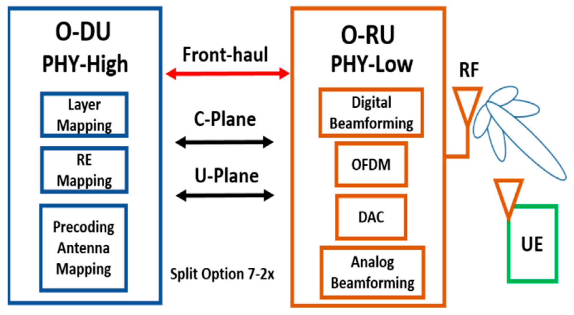
The Split 7-2x option introduces simplified communication interference within O-RAN units, especially in front-haul, where it supports all beamforming technologies (analogue, digital, or hybrid); analogue beamforming deployment modules and amplifies first the signal and then splits it among the antennas of the antenna array; digital beamforming deployment builds first the digital streams of each antenna of the array and then the signals are modulated and amplified and sent by the antennas; hybrid beamforming deployment is a combination of both with several digital streams that, after modulation and amplification, are sent to a number of antennas.
Figure 2 describes the block diagram of the standard beamforming solution in O-RAN, which is hybrid beamforming in the general form.
One of the challenges of Split Option 7-2x in the front-haul interface is the high bandwidth. We suggest using Category B to perform the precoding in O-RU and reduce the transported data from O-DU through the front-haul interface to overcome this challenge. This implementation will lead to inter-RU interferences in O-RU because each O-RU will determine beamforming matrices independently. Thus, it has been suggested to design the beamforming matrices in O-DU through the channel state information (CSI) and produce a precoding beam in O-RU. We propose using the zero-forcing (ZF) algorithm as a potentiality to reduce the interference in received signals while keeping the beamforming in one unit. Moreover, the cost of implantation and hardware complexity will be reduced [
28,
29,
30].
O-RAN suggests the following beamforming methods to achieve acceptable performance in beamforming:
Beamforming indexing method (predefined-beam beamforming). O-DU in this method sends information about the beamforming type to the O-RU based on BeamID, which will carry by the C-pane, and the O-RU reserves this information in a table of beam indexes. This table contains beam weights, frequency domain beam weights, time-domain beam weights, or hybrid beamforming; the BeamID is used as a pointer to a pre-defined beamforming weight vector. Hence, BeamID is only a weight vector value transferred between O-DU and O-RU to register which beam should be used.
Real-time weights method (weight-based dynamic beamforming). The O-DU in this method sends the beamforming weights generated in real-time to the O-RU to be allied with a specific user’s data. A beam index can be assigned (and used in subsequent messages) if the beamforming weights are stable for a period of time. This method has two implementation cases: weight-based dynamic (which are digital and analogue beamforming) and weight-based dynamic (which is hybrid beamforming); in the first case, the beamforming weights can be updated in real-time with the BeamID value allied with the weights. For the second case, two sub-cases are held: (1) both the time-domain and frequency-domain weights may be updated in real-time, and (2) the time-domain beams are fixed while the frequency-domain weights may be updated in real-time.
Beam attributes method (attribute-based dynamic beamforming). The disadvantage of the Real-time weights method requires additional processing capability in the O-RU for modifying transmission to the beam weights provided by the O-DU. Therefore, an adjustment to the previous method has been introduced to obtain the beam attributes method. The adjustment is that the O-RU generated the beamforming weights using a set of beam attributes signalled by the O-DU and carried (to the O-RU) by the C-plane. These attributes are beamwidth (narrow, wide), azimuth and elevation, sidelobe destruction, and beam weights determined by RU. The consequence of this adjustment is that hybrid beamforming is not supported. Due to the weights generated by O-RU, it will be either frequency-domain or time-domain but not hybrid.
Channel information method (channel-information-based beamforming). This method is based on digital beamforming. It is known that digital beamforming is a good solution for capacity and flexibility in the case of a high-traffic communication environment since it offers steerable beams. Each antenna has a dedicated RF signal and path and provides a high number of beams that can be transmuted dynamically with no change in the hardware. Thus, in this method, the O-RU generates beam weights based on the channel information from O-DU. The algorithms can synthesize a drive signal to obtain the maximum of any beam characteristics. However, implementing the precoding in RU will lead to inter-RU interferences in the O-RU. The zero-forcing algorithm (ZF) is one of the algorithms that can be implanted to overcome this interference issue in received signals.
O-RAN specifications have adjusted the front-haul interface by allowing the front-haul interface to carry spatial layers, which means fewer data and reduces the complex timing for O-RU and OCU/O-DU link compared to the 3GPP specifications.
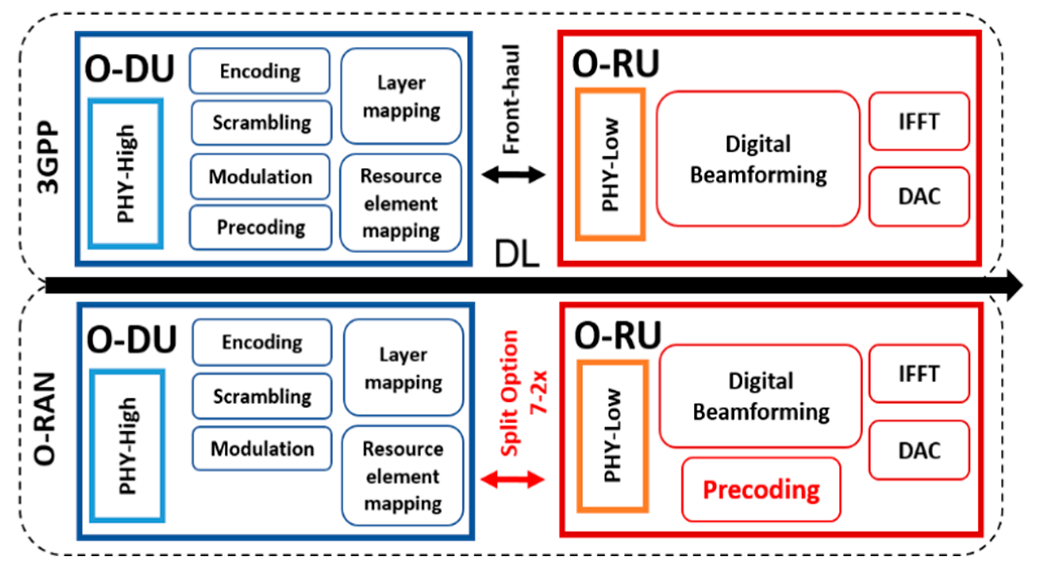
Figure 3 presents the digital beamforming diagram in O-RAN compared to 3GPP.
The comparison in
Figure 3 presents the difference in the implementation of digital beamforming between 3GPP and O-RAN (Category B), where the precoding has been transferred to O-RU. Therefore, this implementation will gain more reliability due to the low channel load in the data flow from O-DU to O-RU, where the link capacity requirement will be lower by reducing the data bit of scheduling and beamforming commands as its one of the main contents in C-plane data flow between the O-DU and O-RU, as shown in
Table 1.
There are two layers in C-Plane messages: the transport layer and application layer. Each layer includes different sections (there are more than eight sections in C-plane): the transport layer and the eCPRI (enhanced Common Public Radio Interface) header include corresponding entries implemented to indicate the message type. The application layer includes ordered fields for control and synchronization. Furthermore, within the application layer, some sections determine the characteristics of the U-plane. Each section carries specific parameters to O-RU individually. These parameters are managed by the management-Plane (M-Plane) and can specify the packet size of the C-plane based on the handled section from O-DU and O-RU.
C-plane section has multibit parameters with different numbers of bits. Some of these parameters define the beamforming method; for example, the weight-based dynamic beamforming method performs the beamforming within O-RU based on parameters carried by the C-plane and transported from O-DU over the front-haul, such as precoding beam weights, which are carried by the BeamID parameter and channel state information. This implementation carries more parameters, leading to a high signal cost due to the high number of bits in the C-plane packet. The channel state information beamforming method, the C-plane packet will carry fewer parameters and reduce the packet size by 40% by abandoning the BeamID parameter and producing precoding beam weights in O-RU based on parameters transported from O-DU such as UE identifier (ueId parameter) and channel state information (ciIsample and ciQsample parameters).
Additionally, the basic calculation formula that can explain and compare the results of reducing the transferred parameters is the channel capacity in the front-haul by using the celebrated Shannon formula:
where
is the channel bandwidth of the front-haul interface,
is the average signal power, and
is the average noise power.
Decreasing the transferred parameters leads to fewer resource blocks, which will raise the average output power of the signal. This concept is essential in the channel state information beamforming method to achieve a lower packet error rate and high latency to support and reduce the complexity of generating the beamforming weight in O-RU, which requires the high performance of CSI data. The outcome results of this concept can confirm that the channel state information beamforming method is acknowledged as a reliable option in high channel traffic to improve the latency and channel capacity by using less recourse blocks and enhancing the signal power compared to the other three beamforming methods mentioned above.
Performing the precoding in O-RU will increase the complexity of implementing in case of the high precoding stream number, resulting in inter-symbol interference in O-RU with non-desired users. To overcome these interference challenges, we suggest using zero-forcing beamforming. The next section explains how the zero-forcing method may be implemented.
4.2. Zero-Forcing Implementation
Zero-forcing beamforming is a method that is widely considered in massive MIMO systems [
11]. Zero-forcing encodes the signal sent to the air interface in such a way that the signals sent to different users are orthogonal. This reduces at the user’s side, the interferences created by the signals sent to other users. The most straightforward approach to zero-forcing implementation is to invert the channel through the pseudo-inverse, called ZF precoding; this technique allows transmitting and receiving data to desired users and nullifying the directions from the interference users. The performance of zero-forcing beamforming depends on the accuracy of received channel status information (CSI) of each user to manage the precoder and beamforming weight vector. This channel carries the signal properties such as propagation features from the transmitter to the receiver, scattering, fading, and power consumption with distance [
31,
32,
33].
For implementing zero-forcing, the BS sends a synchronization message applying the generated precoder
W in the O-RU (here where the beamforming has been applied), with size,
, so that the sampled transmitted signal is:
where
is the precoding matrix, and
is a transmitted symbol vector.
The received signal vector obtained by user
is given by
This signal should be received by the desired user without signals from interference users, where the channel vector for user is , denotes complex conjugate, and is the noise sample (additive white Gaussian noise with zero mean and variance ).
Theoretically the interference signal of user
that can be received by all users is given by:
The goal is nulling the interference signals, and to achieve this scenario we inserted Equation (2) into Equation (3); in general, a received signal is obtained given as in Equation (5).
From the transmit power constraint for user
which is
, we can calculate the interference caused by other users through the received SINR of the
-th user:
The ZF-BF precoding is closely related to the concept of generalized inverses in linear algebra, where each beam generated by the ZF-BF precoder is orthogonal to all the other user channel vectors. In the destination direction, we need to calculate the inverse of channel matrix
and, for this aim, we applied the well-known Moore–Penrose inverse generalization to obtain
and, recalling
denotes an
matrix whose columns are transmit beamforming vectors then the ZF precoding vectors can be expressed as in Equation (7).
where (.)
H denotes Hermitian transpose.
The ZF precoding condition of generating
precoder for user
is orthogonal to all the other users’ channel vectors
such that there is no interference from other users where
; the received SINR for the
k-th user is determined as follows:
4.3. System Model and Simulation Results
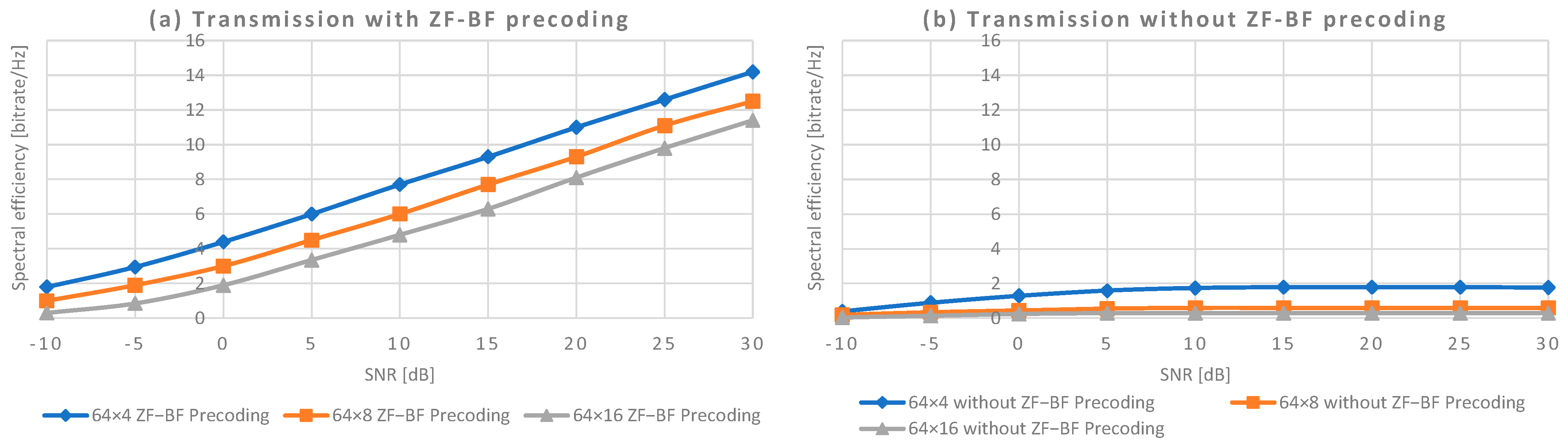
In O-RAN, zero-forcing may be used only in digital beamforming at the O-RU, however the augmented (in comparison to purpose-built 5G implementation) number of hardware operations due to the control of the open RAN interfaces increases the inaccuracies in orthogonality, which results in an increase in the noise of the channel. In order to simulate the benefits of zero-forcing in O-RAN implementation, we separate the component of the channel noise (including O-RU hardware impact) and the interference of the signal sent to other users. The interference will reduce the spectral efficiency (number of bits that may be transmitted per Herz of frequency bandwidth), which is a parameter of the capacity of the system to send information to the user’s mobile device.
In our simulations, we calculate the spectral efficiency for different values of Signal-to-Noise ratios (SNR), so that the channel noise is a parameter that may be estimated for the channel regardless of the use or not of the coding method. The fact that we use O-RAN instead of classical purpose-built 5G network implementation causes lower SNR, and this must be considered in our conclusions. In order to simulate the zero-forcing precoding in beamforming implementation (referred to as ZF BF precoding), we assume a downlink MIMO channel between a base station BS (Base Station) including Nt transmits antennas and K active mobile devices (users). The mobile device owns one antenna. Thus, there are downlink streams from BS to each one of the K mobile devices. The maximum number of users K that can be served simultaneously by the BS is equivalent to the number of RF chains at the BS, that is .
We assume the perfect information of the channel state (which is sent by the users to the BS through the Channel State Information message), so that the BS may send perfectly orthogonal signals to the users.
As far as the air interface is concerned, we assume a Rayleigh fading channel, which is a valid model in urban scenarios [
34]. The channel is frequency-flat (no frequency selectivity) and static (without Doppler effect). The Rayleigh fading model is set to each path independently with null standard deviation and an increasing value of Gaussian noise vector in the channel (SNR). For the channel simulation, Matlab comm.MIMOChannel function is used, which, on its part, makes use of comm.RayleighChannel function for the simulation of the Rayleigh channel.
In our Matlab simulations, we apply digital zero-forcing beamforming (ZF-BF) and compare it with two reference models: the first one is without interferences (one single mobile device or user) and zero-forcing beamforming, the second reference is a transmission with interferences (number of mobile devices higher than one) and without zero-forcing beamforming. Our implementation assumed a variable number of transmitting antennas and a variable number of users (mobile devices) that communicated through the MIMO channel.
The ZF-BF allows receiving a separate received signal at each user, which reduces the total power of the noise and, as a result, increases the signal-to-noise-to-interference ratio (SNIR). This method minimizes the inter-symbol interference (ISI) components in the output (making the ISI zero in a theoretical noise-free cause interference). This means that higher values of SNR (lower noise) should result in better response of the system in the case of zero-forcing precoding. In our results, we assume a SNR range from −10 to 30 dB.
We use Matlab to simulate signal quality by determining the throughput for the k-th user and assuming a downlink massive MIMO system with various transmit antennas and active mobile users; each user has one RF chain. The throughput divided by the bandwidth is the spectral efficiency presented in the following figures.
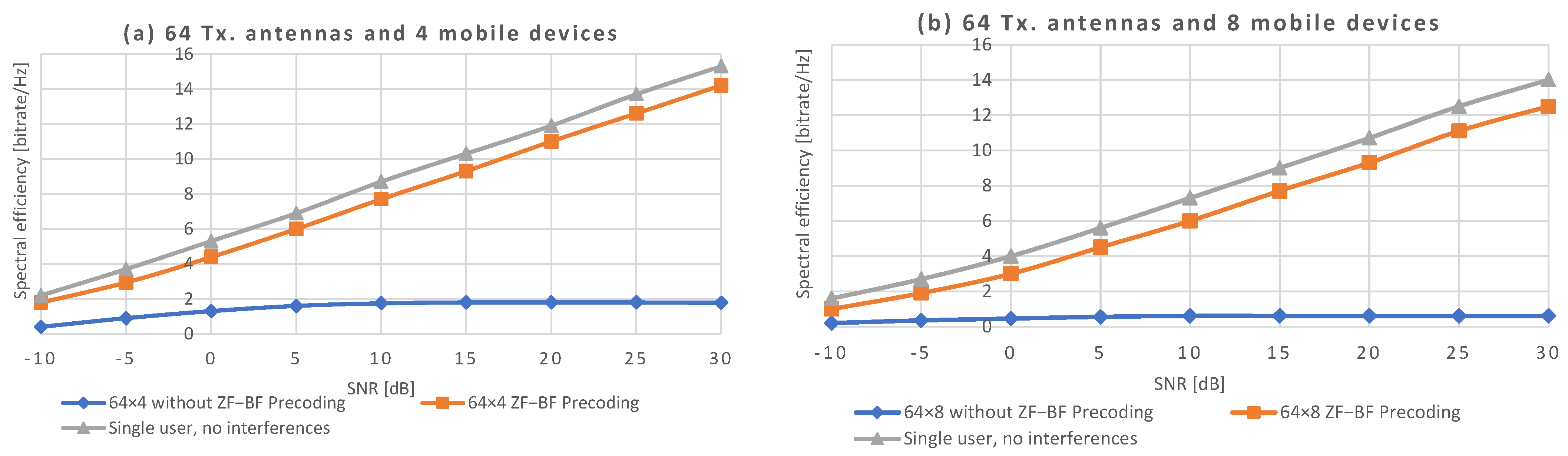
Figure 4 shows the impact of precoding in a noisy channel with multiple antennas and multiple paths. As we can see, regardless of the number of users, beamforming transmission without precoding achieves very low values of spectral efficiency, even when few mobile devices are connected. Really, the apparition of any kind of interference (even one more user in the cell) makes the transmission unfeasible, unless some kind of coding is used. The introduction of ZF-BF can obtain a performance adjacent to the single-user scenario, reducing the interference in the multi-user environment.
In
Figure 4a,b, we may observe that the increase in the number of users from 4 to 8 means causes a falling of the spectral efficiency of around 2 bps/Hz, irrespectively if the system implements zero-forcing coding or not. The next figure aims to better understand the effect of the number of users in the system.
Figure 5 shows the impact of the number of users that provoke interferences.
Figure 5a shows the spectral efficiency when ZF-BF precoding is installed. We may see that, by increasing twice the number of mobile devices in the cell, the efficiency falls around 2 bps/Hz. In other words, when the number of users is doubled, the system needs around 5 dB more SNR to achieve the same spectral efficiency (see, for example, the value of 8 bps/Hz that requires 10, 15 and 20 dB for 4, 8 and 16 users, respectively). For SNR equal to 30 dB, we may observe a slight difference, however we think that this is an effect of the short duration of the simulations.
Figure 5b shows a decrease in the efficiency between 4 and 8 users; however, after that, the increase in the number of users does not have a practical impact on the efficiency. The reason is that the spectral efficiency is then bounded by the white noise, and not by the interferences. In any case, we need to highlight that such values of spectral efficiency make the transmission unfeasible, or at least highly inefficient.
Let us remark that in our simulations, the number of antennas has a null impact on the results, under the condition that this (the number of antennas) is enough for serving the number of mobile devices in the covered area. In radio transmission, the number of Tx antennas has an impact in the SNR of the transmission, so that more antennas may allow a higher bitrate. However, upon a certain signal power, the increase in antennas does not increase the bitrate. This point is known as the bandwidth limit area and means that the bandwidth is the limit of the bitrate, i.e., the efficiency is maximum. The way to increase bitrate in that case is to increase the number of Rx antennas, so that we have more complex MIMO system.
In our simulations, this effect is not demonstrable since we do not have full MIMO transmission, but more a multi-path transmission (the antennas send signal to specific user). As a conclusion, the reduction of spectral efficiency is due to the increase in mobile devices covered by the antenna. In the case of a high number of mobile devices (high interference), we suggest applying minimum mean square error (MMSE). MMSE reduces the interference by reflecting the noise.
The MMSE is more accurate than zero-forcing and serves a wide range of channel state conditions (different
SNR). In the case of MMSE, Equation (7) may be re-written as in Equation (9). Let us remark that we do not assume orthogonality in Equation (9).
The MMSE matrix is simply the inverse of the channel matrix (H−1).
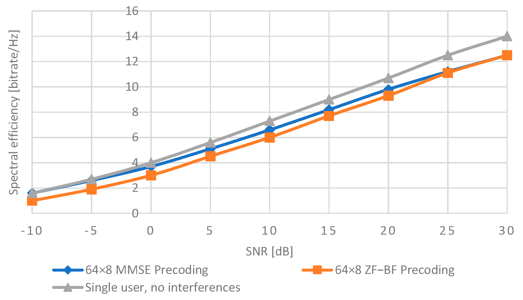
Figure 6 shows the differences of the spectral efficiency when we provide MMSE algorithm instead of ZF-BF.
The results show that MMSE performance is higher than the zero-forcing algorithm in case of low SNR, whereas, for high values of SNR, the difference between zero-forcing and MMSE clearly disappears. This is because Equation (9) approximates to Equation (7) when SNR is very high. From the practical point of view, this means that in scenarios where the antenna may reach high power transmission, MMSE is not necessary (which may reduce system complexity). In the case of O-RAN, the implementation of the O-RU hardware implies that the SNR is reduced. In that case, the use of MMSE is recommendable, even when this introduces more complexity in the transmission system.
Our results show that precoding (both ZF-BF and MMSE-BF) may obtain a high reduction of interferences in the channel interface, so that high bitrate and low latency requirements are reachable. This is also achieved thanks to the implementation of precoding in the O-RU, jointly to the digital beamforming, so that the data transported in the front-haul are minimized.


 ,
, 


