Article

A Type-2 Fuzzy Controller to Enable the EFR Service from a Battery Energy Storage System

by
Sergio Cantillo-Luna
1,
Ricardo Moreno-Chuquen
1,*,
Francisco Gonzalez-Longatt
2,* and
Harold R. Chamorro
3
1
Faculty of Engineering, Universidad Autónoma de Occidente, Cali 760030, Colombia
2
Department of Electrical Engineering, Information Technology and Cybernetics, University of South-Eastern Norway, 3918 Porsgrunn, Norway
3
Department of Electrical Engineering, KTH, Royal Institute of Technology, 114 28 Stockholm, Sweden
*
Authors to whom correspondence should be addressed.
Energies 2022, 15(7), 2389; https://doi.org/10.3390/en15072389
Submission received: 3 February 2022 / Revised: 1 March 2022 / Accepted: 21 March 2022 / Published: 24 March 2022
(This article belongs to the Special Issue Energy Storage for Grid Integration of Renewable Energy)

Abstract

:
The increased use of distributed energy resources, especially electrical energy storage systems (EESS), has led to greater flexibility and complexity in power grids, which has led to new challenges in the operation of these systems, with particular emphasis on frequency regulation. To this end, the transmission system operator in Great Britain has designed a control scheme known as Enhanced Frequency Response (EFR) that is especially attractive for its implementation in EESS. This paper proposes a Type-2 fuzzy control system that enables the provision of EFR service from a battery energy storage system in order to improve the state-of-charge (SoC) management while providing EFR service from operating scenarios during working and off-duty days. The performance of the proposed controller is compared with a conventional FLC and PID controllers with similar features. The results showed that in all scenarios, but especially under large frequency deviations, the proposed controller presents a better SoC management in comparison without neglecting the EFR service provision.

1. Introduction

In recent years, the widespread use of distributed energy resources (DER) such as self-generation, distributed generation, and demand response together with advances in electric energy storage systems have facilitated the integration of demand-side resources into the grid. This process has gradually led to greater flexibility, but at the same time it has generated new challenges in the power system operation, which has increased the demand for frequency regulation due to imbalances between power supply and demand (i.e., generation surplus produces higher frequency and demand surplus produces lower frequency) [1,2,3].
Therefore, more severe and long-lasting frequency deviation effects are expected, as well as the reduction of system inertia due to the replacement of conventional plants by renewable and distributed generators [4,5]. However, the incursion of different electric energy storage systems (EESS) is shown as an operational asset for faster frequency response than the current primary response controls. These assets contribute to an adequate frequency control under this new flexible grid paradigm, and therefore allows a greater integration of different energy resources distributed and decentralised resources.
Accordingly, regions such as Great Britain (through its TSO, the National Grid plc, NG), which is responsible for regulating system frequency, have developed a service to improve frequency management by keeping it as close as possible to 50 Hz under normal operating conditions using the fast response capability of EESS (less than 1.0 s after registering a frequency deviation) allowing for state-of-charge (SoC) management between service windows, which was not possible in the existing frequency response services (i.e., first, secondary and high-frequency). This service is known as Enhanced Frequency Response (EFR) [6].
Therefore, dealing with intermittent renewable resources requires new approaches for frequency regulation. The EESS could provide fast regulation but at the same time the charging and discharging should be considered in order to satisfy operational battery conditions, for instance, in [7] the authors propose an algorithm to do peak shaving using a formulation based on minimising of the SoC cost and the load cost. Another perspective has been addressed in [8], where the authors examine the operation of a grid-connected lithium-ion battery from a a battery lifetime perspective considering the cycling of re-establishing SoC and gaining insights to consider for operation. A development of experiments with a LiFePO4 battery are performed in [9] with real data for an transmission operator obtaining evidence about the trade-off between expected charging and discharging cycles and the frequency control. Furthermore, some recent articles have already oriented these energy assets to provide frequency response such as batteries [10,11], flywheels [12], multi-energy storage systems [13], Gorostiza 2020, and electric vehicles [14], where they provide an overview but focus on how to provide frequency control in power system applications.
The modelling for energy storage systems is a relevant topic today given the integration and the provision of auxiliary services. The modelling of storage systems for electricity markets have been studied in different papers [15,16]. Others authors have addressed the modelling of storage in microgrids [17,18]. However, the SoC management is considered in terms of economic operation without including a stability study about frequency control.
On the other hand, fuzzy logic inference considering uncertainty among its membership functions (or Type-2 MFs) has been recently implemented in different research areas such as energy management (i.e., EESS, electric vehicles, power systems) [19,20,21,22], nonlinear systems control [23,24,25], electric load forecasting [26,27], among others related areas, due to its better uncertainty and variability handling compared with other control techniques [28].
In this paper, we propose a type 2 FLC-based control system to enable EFR service to the power grid through a battery energy storage system (BESS) dynamic model considering the management of its state-of-charge, and the different real operating conditions (i.e., the system frequency time series during working and off-days). This controller will be compared to a conventional fuzzy logic controller under these criteria to assess its performance.
This paper contains three additional sections. In Section 2, the model for battery energy storage system is presented for a generic lithium-ion battery, then the frequency controller is developed based on frequency deviation and power response and the logic controller for the SOC using a novel fuzzy type-2. In Section 3, we present results and the appropriate discussion about the performance of the type-2 fuzzy controller to enable the EFR services including various operational scenarios compared with a conventional FLC and a PID controller. Finally, Section 4 presents some concluding remarks.

2. Materials and Methods

The scope of this article deals with the development of a Type-2 fuzzy logic controller (T2-FLC), in order to enable the enhanced frequency response from a electric energy storage system (in this case, a lithium-ion battery) considering frequency deviation and SoC management. A description of the most essential features of this approach are given below.

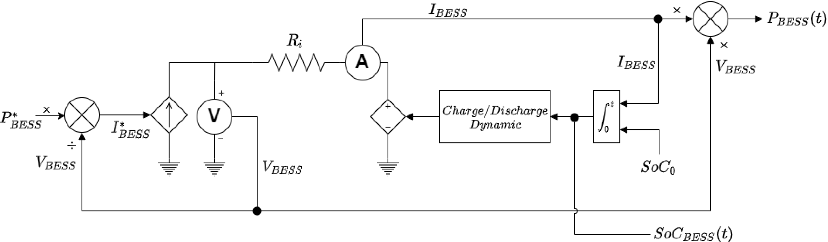
2.1. Battery Energy Storage System Modelling

A generic model of a lithium-ion (Li-ion) battery model with similar charge and discharge dynamics is used in this paper. The battery voltage without load E B E S S * and its state of charge S o C are modelled as a functions of the battery current I B E S S as presented in Equations (1) and (2) [13,14,29].
E B E S S * = E B E S S 0 + K E S o C B E S S ( t ) + α e β 0 t I B E S S ( t ) d t
S o C B E S S = S o C 0 1 Q B E S S 0 t I B E S S ( t ) d t
where E B E S S 0 represents the open-circuit voltage (V) in the battery, α is the exponential zone amplitude of the battery (V), Q B E S S is the battery capacity ( A h ), K E is the polarisation voltage, and β is the inverse of the exponential zone time constant ( A h ).
It is important to highlight that for this BESS model, thermal or ageing effects that affect the performance of this type of batteries have not been considered [30]. On the other hand, a block in series to this model is incorporated to represent the power conversion delay as a protection measure to unreal operating conditions (e.g., current flows when the BESS state of charge is zero) [14]. The equivalent circuit and related blocks are shown in Figure 1 [13,29].

2.2. Enhanced Frequency Response (EFR)

The frequency controller implemented in this paper, is based on the EFR service implemented by the TSO of GB (i.e., National Grid). This service dynamically delivers a change of active power proportional to changes in system frequency. This mechanism has been explicitly designed for energy storage systems, due to its fast response to frequency deviations (i.e., 1.0 s from the event). Likewise, this service includes an area dedicated exclusively to the state-of-charge management [13,31].
Moreover, this service presents three zones according to the magnitude of the deviation in the system frequency as presented in Table 1. For frequency deviations at or below the frequency threshold denoted by V (i.e., frequency below the desired value), the EESS must follow a single power reference, proportional to the frequency and cannot manage its state-of-charge. When the frequency deviation is at or above the frequency threshold denoted by Y (i.e., frequency above the desired value), the EESS must also follow a single power reference, proportional to the frequency. As in the previous region, there is also no state-of-charge management.
Finally, when the frequency deviation lies within the region between V and Y, the EESS response must lie within the envelope formed by these points. Within that region, the EESS can manage its state of charge by changing the control reference parameter ρ between −1 and 1. So, the output power reference of the EESS in terms of ρ can be expressed as show in Equation (3) [29].
P E E S S * = 0.5 P u p ( ρ + 1 ) 0.5 P l o ( 1 ρ )
where P u p and P l o are functions of the sampled instantaneous frequency value describing the upper and lower services envelopes (see Table 1), and P E E S S * is the normalised output power reference of the EESS. This equation describes the different scenarios in the previous described zones as a function of injecting or absorbing power according to the frequency deviation in the power grid instead of using a power derivative over time like the conventional EFR (i.e., when 0 < ρ 1 the ESS injects power to the network reducing its load state, while if 1 ρ < 0 the opposite action occurs).
On the other hand, it is essential to highlight that this service presents two modes according to the dead-band amplitude (i.e., the region between W and X points in Table 1) for the proportional power response range outside this region: the wideband (WB) with Δ f = ± 0.05 Hz, and the narrowband (NB) with Δ f = ± 0.015 Hz. The EFR service is considered WB for the development of the following sections of this paper. The details of the specific points defining the EFR service envelopes -based on [32]- for both mode settings are shown in Table 1.
One of the most important metrics for determining EFR quality of service and payment as defined by the NG is known as the service performance measure (SPM). This metric is calculated on a second by second basis as the ratio between the EFR power reference to EESS asset and the service envelopes (i.e., the SPM will be 100% if during the whole operation time, EESS operation is between the area delimited by service envelopes, otherwise a penalty corresponding to a proportional payment reduction is received for over or under-producing).

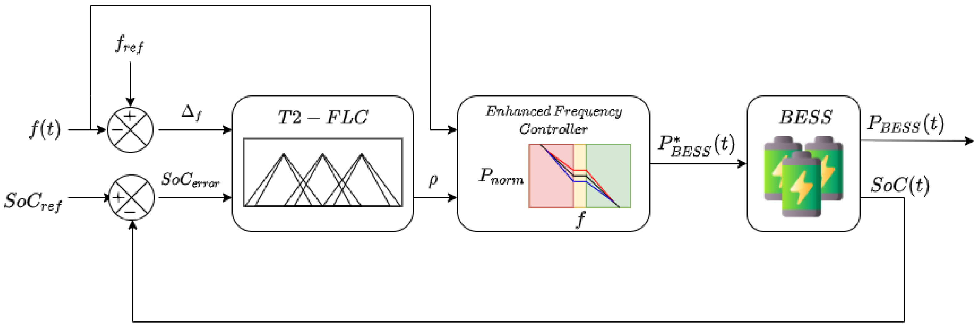
2.3. State of Charge Management: Type-2 Fuzzy Logic Controller (T2-FLC)

As previously mentioned, the EFR service provides an ideal profile and two service envelopes (upper and lower according to the frequency deviation of the system). In the area bounded by these envelopes (or pre-fault), it is possible to perform state-of-load management of assets with finite capacity such as the different types of ESS. On the other hand, outside this region (i.e., post-fault) there is no possibility to perform SoC management since the priority is to serve the grid requirements. Therefore, this paper proposes a controller that activates the EFR service from a battery energy storage system (BESS).
This controller is designed to manage the state of charge of the BESS system, while ensuring the EFR service is supplied. For this case, a Type-2 fuzzy logic controller (T2-FLC) is presented. This control technique was chosen for the ease of incorporating the operating rules based on expert knowledge in an intuitive way as required (in this case, the conditions for injecting or absorbing power from the battery system) and its implementation in systems where obtaining it in an analytical form presents great difficulty. On the other hand, by adding uncertainty to the operation of the controller, the occurrence of adverse phenomena associated with variability, as in the case of system frequency and real time SoC measurement, can be mitigated.
It is important to highlight that one of the most essential features of EFR service is the state of charge management of the energy storage asset (i.e., choosing how many and when to absorb/deliver energy to the power grid considering frequency deviation) as long as its output is within the operating envelopes of the service. The ideal value to maintain in the ESS SoC would be 50% [33]. However, this set-point also can depend on the asset owners interest.
Considering this context, the proposed controller presents two inputs associated with the frequency deviation Δ f , and the battery state-of-charge error S o C e r r o r obtained by deducting the setpoint and the measured value in the BESS (i.e., if S o C e r r o r < 0 , more stored energy than required. If S o C e r r o r > 0 , more delivered energy than required), and a single output corresponding to the power reference ( ρ ), which in this case is normalised between 1 and −1 and responds to the EFR control dynamics described in Equation (3). This equation applies the technical operating parameters of the EFR service (see Table 1), simplifying the requirements and reducing the response time of the controller compared to its full version (requires derivative calculations). The schematic of the proposed controller is shown in Figure 2.
For the proposed controller design, the fuzzy logic controller presented in [29] has been used as an initial approach, where expert knowledge of the operation and EFR service has been incorporated, as well as the logical aspect of the whole process behaviour, all this worked under Methodology presented in [34]. Starting from this framework, the different modifications (i.e., the definition of uncertainty footprint and scaling) have been made for the development of the T2-FLC. Due to the close similarity between the conventional FLC and the proposed Type-2 FLC processes, the inference processes with slight differences are carried out as follows:
  • Fuzzification: The system frequency deviation and the BESS state of charge error are the numerical inputs. Those variables are transformed into linguistic variables associated with membership functions (MFs). In this particular case, triangular MFs are selected since they are intuitive and straightforward to design and modify according to requirements.
    For this case, the membership functions representing the “zero deviation” (Z) are narrower than the other MFs only for both inputs. On the other hand, the “Positive” (P) and “Large Positive” (LP) variables require different control actions, but a higher amplitude can be chosen with adequate results for this application. The same is true for the “Negative” (N) and “Large Negative” (LN) MFs. It is important to highlight that these linguistic variables were given to all inputs and outputs to keep a coherent framework.
    Unlike conventional FLC, fuzzification of these variables requires primary (or conventional) and secondary variables to create the footprint of uncertainty (FOU) needed to add variability and robustness to these Type-2 MFs. For this case, the two secondary variables present the same degree of membership (or scale) of the primary ones, but with a 30% reduction of their area (base).
  • Inference: In this process, the MFs from the previous step are combined with a rule base from the process expert knowledge as presented in Table 2 in order to produce a conclusion. It is important to highlight that for this paper, a Mamdani type fuzzy inference system was used. Therefore, this conclusion corresponds to a fuzzy output (according to each controller, i.e., standard fuzzy output for the conventional FLC and type 2 for the proposed T2-FLC) that requires defuzzification.
    This stage is exactly the same for both conventional and type-2 fuzzy logic controllers, due to both using the same rule base. However, the inference output of the controllers requires a different defuzzification process.
  • Defuzzification: Finally, at this stage the inference output is transformed back into a numerical output using the related membership functions (with similar ranges, shapes and slopes), which in this case corresponds to the control reference ρ . As in the case of fuzzification, the output variable also requires primary and secondary MFs for the required FOU (same degree and type of membership of the primary variables, but also with a 30% area reduction). Moreover, in order to adapt to any dynamic system, Type-2 FLCs feature a type reducer (for this case, a Centroid type-reduction [35]) at this stage to deliver conventional outputs.

3. Results and Discussion

The performance of the proposed Type-2 FLC controller to enable the EFR service of a BESS compared with conventional FLC and PID (as a classical approach) controllers, considering minimising the state-of-charge error while keeping the SPM metric as high as possible, is presented and discussed in this section. Therefore, two scenarios are evaluated, with time series of GB system frequency data from July 2021 at one-second resolution, in order to consider the frequency deviation data to manage the BESS absorbing/delivering behaviour. The PID controller used operates directly on the state-of-charge and meets the transfer function presented in Equation (4).
P I D ( s ) = k p + k i s + k p · N f 1 + N f s
where k p , k i , and k d denote the proportional, integral and derivative gain coefficients, respectively, and N f indicates the filter coefficient. The PID parameters used in for this comparison are the following: k p = 2.5 , k i = 1 × 10 5 , k d = 1 , and N f = 1 .
All simulations were completed by a computer (PC) running Windows® with an Intel® Xeon W-3235 processor @3.3 GHz with 16.00 GB RAM, using MATLAB® R2021a (9.10.0.1602886) [36] under Simulink framework. This equipment was provided by the Digital Energy Systems and Lab (or DIgEnSys-Lab), the real-time hardware-in-the-loop laboratory that includes cutting-edge facilities for real-time simulation for research related to solutions to key challenges related to carbon-neutral energy systems, where Prof. F.G-L’s research group is located.

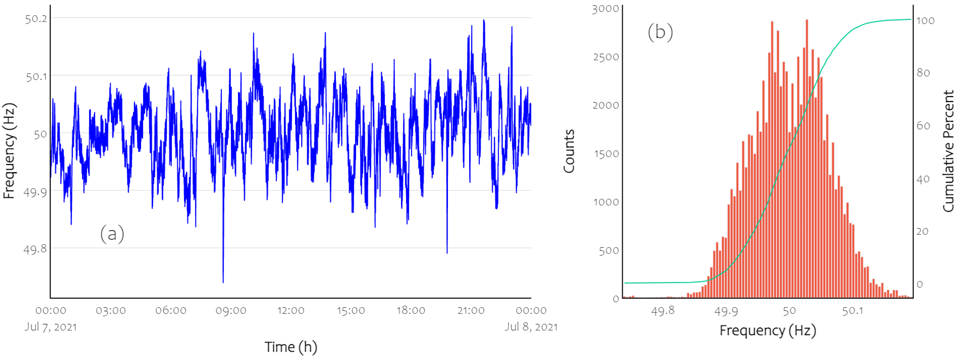
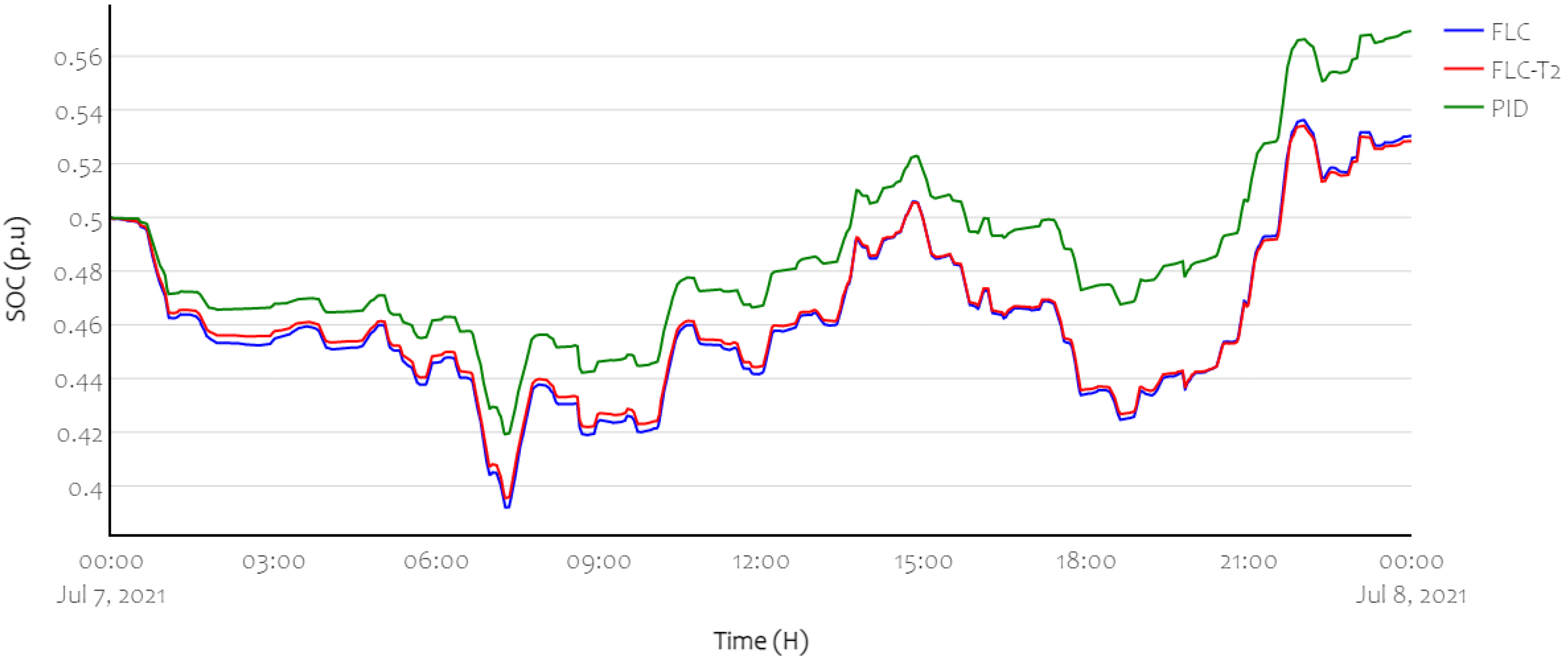
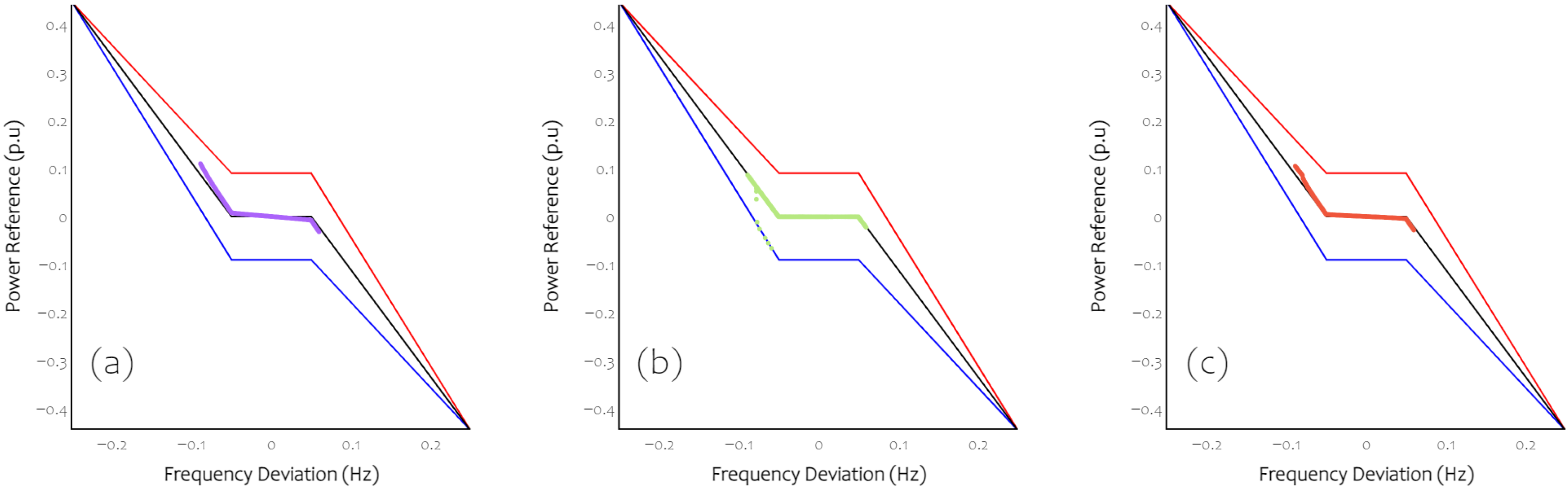
3.1. Scenario 1: Frequency Deviation on Working Days

This scenario refers to the operation of the BESS delivering the EFR service to the power grid under real operating conditions (i.e., system frequency data) during working days, where the energy load is higher than weekends. Figure 3a shows a time-domain plot of a 24-h sample of the NG frequency data corresponding to 7 July 2021, which is used to test the FLC-based controllers to enable the EFR service. Figure 3b shows the histogram and cumulative distribution function (CDF) of frequency time series. It can be seen that the frequency remains inside the operational range (±0.2 Hz) during the 99.93% time considered (i.e., there are time periods where the frequency deviation is greater than allowed by the EFR service).
On the other hand, it is evident the frequency is below nominal 51.26% of the time. This means that during a large part of the analysis time, the battery energy storage system will have to deliver more energy than it will be able to absorb, which is consistent with the scenario conditions. Therefore, the SoC of the BESS has decreased by 10% at its point of highest discharge and grown by 3.5% on average at its point of maximum BESS charge relative to its initial value for both controllers. However, for all cases, the final state of charge was slightly above the initial value (56.9, 53.6 and 52.2% for PID Controller, T2-FLC and FLC, respectively). This behaviour is also described by the histogram distribution.
It can also be seen that during the operation time, all the proposed controllers displayed similar behaviour with the exception of the extreme points of consumption or absorption (i.e., highest frequency deviations), where there is a more smoothed behaviour (i.e., consumption/absorption ratio) by the type-2 FL controller where it tries to maintain the state of charge as close as possible to the desired value, as shown in Figure 4. This performance also indicates that this T2-FLC controller is delivering less energy to the grid (4.01 MWh versus 4.29 MWh injected by the system with conventional FLC, and −9.14 MWh injected by the system with PID controller).
This Figure also shows that in the case of the PID controller, there is a power absorption trend in this case. This can be evidenced in the maximum deviation point for the BESS discharge, where the SoC level is not as low as in the fuzzy logic based controllers. However, in the total energy it is evident that there is no better management of these resources as in T2-FLC.
Additionally, to verify the correct operation of the EFR service by the controllers, the reference signal ρ is plotted (scatter) against the frequency deviation value (nominal versus actual value) during the 24 h of operation. This plot was made together with the envelopes of the EFR wideband service for each controller as shown in Figure 5. In this case, it can be seen that the reference signal points for all controllers are all within the service envelope, thus achieving an SPM of 100%, but they are not exactly in the service reference, since in this case these controllers are managing the BESS state-of-charge.

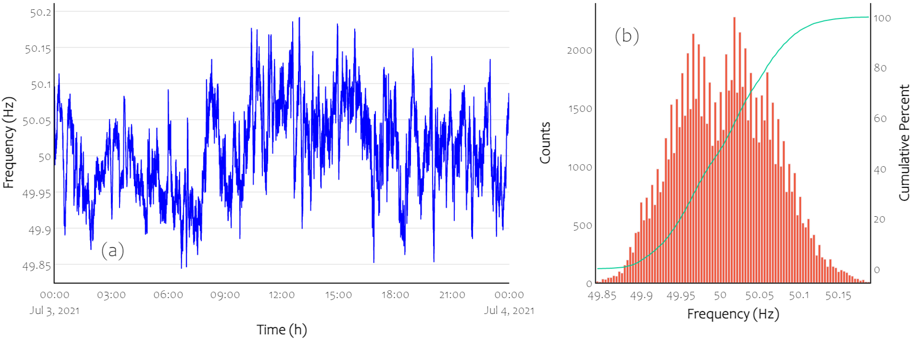
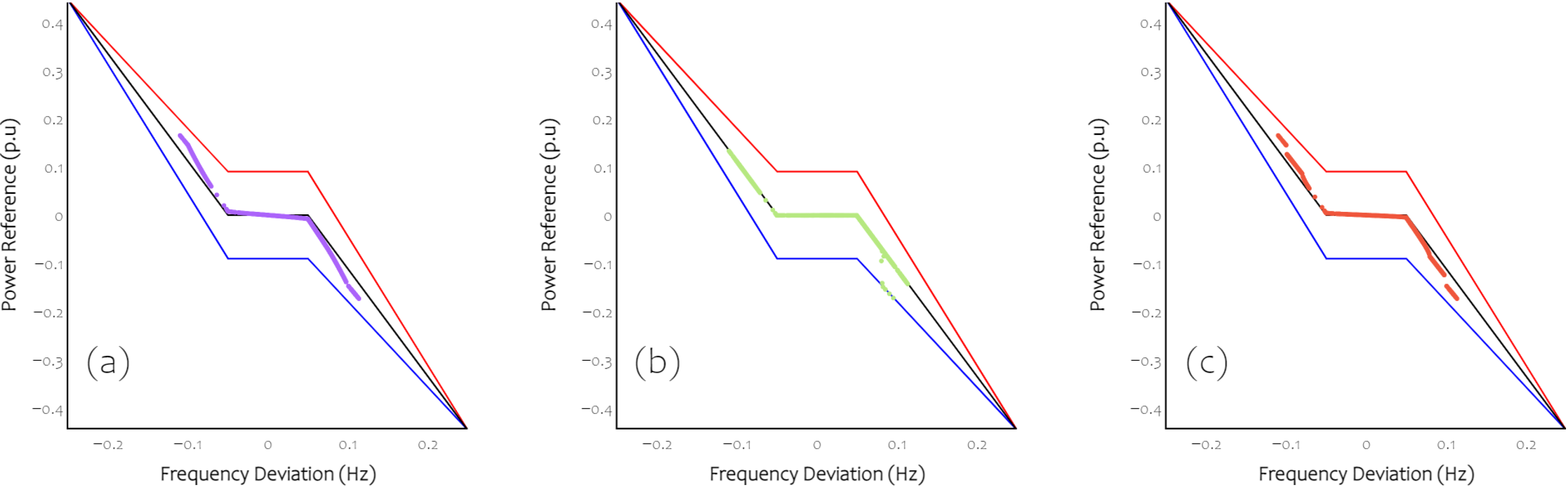
3.2. Scenario 2: Frequency Deviation on Weekend

In this scenario, it refers to the operation of the BESS providing EFR service to the power grid under real operating conditions (i.e., system frequency data) but unlike the previous scenario, this occurs during an off-duty day, where the power demand is comparatively lower. Figure 6a shows a time-domain plot of a 24-h sample of the NG frequency data corresponding to 3 July 2021, which is used to test the FLC-based controllers to enable the EFR service. Figure 6b shows the histogram and cumulative distribution function (CDF) of the related frequency time series. It can be seen that the frequency remains inside the operational range (±0.2 Hz) during all time considered unlike the previous scenario.
Moreover, it is evident the frequency is below nominal 47.66% of the time. This means that during a large part of the analysis time, the battery energy storage system will have to absorb more energy than it will be able to deliver. Therefore, the SoC of the BESS has decreased by 15% at its point of highest discharge and grown by 18% on average at its point of maximum BESS charge relative to its initial value for both controllers. However, for both cases, the final state-of-charge was slightly above the initial values (70.1, 67.1 and 68.5% for PID, T2-FLC, and FLC, respectively).
Again, it can be seen that during the operation time that although all controllers present similar behaviours, in this case when the BESS discharge reaches its maximum point, the type 2 FLC controller presents a smoother behaviour since it tries to maintain the state of charge as close as possible to the desired value (35% versus 33.8% and 38.0% of the conventional FLC and PID, respectively), as shown in Figure 7. This behaviour again indicates that this controller delivers less total energy to the grid (24.95 MW versus 25.35 MW and 27.64 MW delivered by the system with the conventional FLC and the PID controller, respectively).
To verify the correct operation of the EFR service by the controllers, the reference signal is plotted (dispersion) against the frequency deviation value (nominal versus actual value) during 24-h operation. This plot was made together with the envelopes of the EFR broadband service for each controller as shown in Figure 8. In this case, it can be seen that the reference signal points for both controllers are all within the service envelope, thus achieving an SPM of 100%, but they are not exactly in the service reference, since in this case all proposed controllers are again managing the BESS SoC.
However, unlike the previous scenario there is a smaller dispersion of the different power references, given the significant reduction in energy demand during a day off compared to a working day, so that for both controllers this scenario can be less demanding and therefore make SoC management more meaningful.
Overall, the results presented in the two scenarios have shown that although both controllers share similar components (i.e., rule base and membership function shapes), the introduction of uncertainty components in the controller (i.e., Type-2 functions) significantly modify the system behaviour, especially when there are large frequency deviations, prioritising to maintain the SoC as close as possible to the reference value (i.e., 50%) without losing efficiency in providing the EFR service (all controllers with 100%) as shown by indicators summarised in Table 3, where S O C 0 and S O C F represent the BESS SoC at the instant when the EFR service is started and at the end of the time series, respectively, S O C R e f represents the BESS SoC reference set by the operator and managed by the proposed fuzzy logic based controllers.
For both scenarios, it can be seen that the final SoC of the system with the type-2 FLC is closer to the desired one, thanks to the smoothing of the control reference applied to the EFR controller. This same feature also evidences a slight reduction in the energy injected to the grid, which is also a desired circumstance in operational terms. On the other hand, in relation to the EFR service provision to the grid, none of the controllers used in this paper had issues with power references outside the service envelopes (i.e., 100% SPM for both). Therefore, there was no penalty.

4. Conclusions

This paper presents the development of a controller based on fuzzy logic with uncertainty (or Type 2 FLC), which facilitates BESS to provide wideband EFR service while being able to manage the state of charge of such assets as long as it is within the service envelopes by restricting the control signal. Likewise, this controller can mitigate real-time state of charge measurement errors (or uncertainty), so its performance will not be significantly affected compared to other types of controllers (e.g., PID, conventional FLC, among other approaches), since it is necessary to accurately estimate the EESS SoC in real time, which is difficult to achieve.
The proposed controller has improved the ability of the BESS to manage its state-of-charge without decreasing its quality, a key element for assets with finite power delivery capabilities for profit (higher remuneration for better SPM values, which in this case was 100% in all proposed scenarios and controllers). This was accomplished by constraining the EFR control signal through the expert knowledge required in this type of controller, so that the output power of the BESS was kept within the limits of the EFR service envelopes.
On the other hand, it is important to emphasize that the control developed does not depend on the specific features of the EESS. This means that it can be applied to other energy storage technologies (e.g., flywheel, ultra-capacitor) and sizes. In this way, future work could explore the effects of the controller in relation to different events such as cyclic ageing of the BESS, the state-of-charge measurement uncertainty, other EFR services profiles, among others, as well as different modifications to improve the controller performance (e.g., types of membership functions, footprint of uncertainty width, among others).

Author Contributions

Conceptualisation, R.M.-C.; Methodology, S.C.-L., F.G.-L. and R.M.-C.; Software, S.C.-L.; Validation, S.C.-L., F.G.-L. and R.M.-C.; Formal analysis, S.C.-L.; investigation, S.C.-L., R.M.-C. and F.G.-L.; Data curation, S.C.-L.; writing—original draft preparation, S.C.-L., R.M.-C., H.R.C. and F.G.-L.; Writing—review and editing, S.C.-L., R.M.-C., H.R.C. and F.G.-L.; Visualisation, S.C.-L.; Supervision, R.M.-C., F.G.-L. and H.R.C.; Funding acquisition, F.G.-L. All authors have read and agreed to the published version of the manuscript.

Funding

This research received no external funding.

Institutional Review Board Statement

Not applicable.

Informed Consent Statement

Not applicable.

Acknowledgments

The authors would like to thank the support of the Universidad Autónoma de Occidente in Cali, Colombia.

Conflicts of Interest

The authors declare no conflict of interest.

Abbreviations

The following abbreviations are used in this manuscript:
FLCFuzzy Logic Controller
GBGreat Britain
EESSElectric Energy Storage System
EFREnhanced Frequency Response
FOUFootprint of Uncertainty
NGNational Grid plc
NBNarrow band service for frequency response
SoCState of Charge
SPMService Performance Measure
TSOTransmission System Operator
T2-FLCType-2 Fuzzy Logic Controller
WBWide band service for frequency response

References

  1. An, H.; Yang, J.; Yang, W.; Cheng, Y.; Peng, Y. An Improved Frequency Dead Zone with Feed-Forward Control for Hydropower Units: Performance Evaluation of Primary Frequency Control. Energies 2019, 12, 1497. [Google Scholar] [CrossRef] [Green Version]
  2. Greenwood, D.; Lim, K.; Patsios, C.; Lyons, P.; Lim, Y.; Taylor, P. Frequency response services designed for energy storage. Appl. Energy 2017, 203, 115–127. [Google Scholar] [CrossRef]
  3. Weedy, B.M.; Cory, B.J.; Jenkins, N.; Ekanayake, J.B.; Strbac, G. Electric power systems; John Wiley & Sons: Hoboken, NJ, USA, 2012. [Google Scholar]
  4. Ashton, P.M.; Saunders, C.S.; Taylor, G.A.; Carter, A.M.; Bradley, M.E. Inertia estimation of the GB power system using synchrophasor measurements. IEEE Trans. Power Syst. 2014, 30, 701–709. [Google Scholar]
  5. Ulbig, A.; Borsche, T.S.; Andersson, G. Impact of low rotational inertia on power system stability and operation. IFAC Proc. Vol. 2014, 47, 7290–7297. [Google Scholar]
  6. National Grid ESO. Enhanced Frequency Response. 2022. Available online: https://www.nationalgrid.com/uk/electricity/balancingservices/frequency-response-services/enhanced-frequency-response-efr?overview (accessed on 13 January 2022).
  7. Reihani, E.; Sepasi, S.; Roose, L.R.; Matsuura, M. Energy management at the distribution grid using a Battery Energy Storage System (BESS). Int. J. Electr. Power Energy Syst. 2016, 77, 337–344. [Google Scholar]
  8. Stroe, D.I.; Knap, V.; Swierczynski, M.; Stroe, A.I.; Teodorescu, R. Operation of a Grid-Connected Lithium-Ion Battery Energy Storage System for Primary Frequency Regulation: A Battery Lifetime Perspective. IEEE Trans. Ind. Appl. 2017, 53, 430–438. [Google Scholar] [CrossRef]
  9. Gatta, F.M.; Geri, A.; Lamedica, R.; Lauria, S.; Maccioni, M.; Palone, F.; Rebolini, M.; Ruvio, A. Application of a LiFePO4 Battery Energy Storage System to Primary Frequency Control: Simulations and Experimental Results. Energies 2016, 9, 887. [Google Scholar] [CrossRef] [Green Version]
  10. Stroe, D.I.; Knap, V.; Swierczynski, M.; Stroe, A.I.; Teodorescu, R. Suggested operation of grid-connected lithium-ion battery energy storage system for primary frequency regulation: Lifetime perspective. In Proceedings of the 2015 IEEE Energy Conversion Congress and Exposition (ECCE), Montreal, QC, Canada, 20–24 September 2015; pp. 1105–1111. [Google Scholar]
  11. Sánchez, F.; Gonzalez-Longatt, F.; Rodríguez, A.; Rueda, J.L. Dynamic data-driven SoC control of BESS for provision of fast frequency response services. In Proceedings of the 2019 IEEE Power &Energy Society General Meeting (PESGM), Atlanta, GA, USA, 4–8 August 2019; pp. 1–5. [Google Scholar]
  12. Zhang, F.; Tokombayev, M.; Song, Y.; Gross, G. Effective flywheel energy storage (FES) offer strategies for frequency regulation service provision. In Proceedings of the 2014 Power Systems Computation Conference, Wroclaw, Poland, 18–22 August 2014; pp. 1–7. [Google Scholar]
  13. Sanchez, F.; Cayenne, J.; Gonzalez-Longatt, F.; Rueda, J.L. Controller to enable the enhanced frequency response services from a multi-electrical energy storage system. IET Gener. Transm. Distrib. 2019, 13, 258–265. [Google Scholar]
  14. Sami, S.S.; Cheng, M.; Wu, J. Modelling and control of multi-type grid-scale energy storage for power system frequency response. In Proceedings of the 2016 IEEE 8th International Power Electronics and Motion Control Conference (IPEMC-ECCE Asia), Hefei, China, 22–26 May 2016; pp. 269–273. [Google Scholar]
  15. Pozo, D.; Contreras, J.; Sauma, E.E. Unit commitment with ideal and generic energy storage units. IEEE Trans. Power Syst. 2014, 29, 2974–2984. [Google Scholar]
  16. Mohamed, F.A.; Koivo, H.N. System modelling and online optimal management of microgrid with battery storage. In Proceedings of the 6th International Conference on Renewable Energies and Power Quality (ICREPQ’07), Seville, Spain, 29–30 March 2007; pp. 26–28. [Google Scholar]
  17. Jamaica-Obregón, J.; Moreno-Chuquen, R.; Florez-Cediel, O.D. Optimal operation of grid-connected microgrids with photovoltaic generation and storage. Int. Rev. Electr. Eng. (IREE) 2021, 16, 50–59. [Google Scholar]
  18. Gil-González, W.; Montoya, O.D.; Grisales-Noreña, L.F.; Cruz-Peragón, F.; Alcalá, G. Economic dispatch of renewable generators and BESS in DC microgrids using second-order cone optimization. Energies 2020, 13, 1703. [Google Scholar]
  19. Martinez, J.S.; John, R.I.; Hissel, D.; Péra, M.C. A survey-based type-2 fuzzy logic system for energy management in hybrid electrical vehicles. Inf. Sci. 2012, 190, 192–207. [Google Scholar]
  20. Nechadi, E.; Harmas, M.; Hamzaoui, A.; Essounbouli, N. Type-2 fuzzy based adaptive synergetic power system control. Electr. Power Syst. Res. 2012, 88, 9–15. [Google Scholar]
  21. Solano Martínez, J.; Mulot, J.; Harel, F.; Hissel, D.; Péra, M.C.; John, R.I.; Amiet, M. Experimental validation of a type-2 fuzzy logic controller for energy management in hybrid electrical vehicles. Eng. Appl. Artif. Intell. 2013, 26, 1772–1779. [Google Scholar] [CrossRef]
  22. Moghadam, H.; Mohammadzadeh, A.; Vafaie, R.; Tavoosi, J.; Khooban, M. A type-2 fuzzy control for active/reactive power control and energy storage management. Trans. Inst. Meas. Control. 2021, 44, 1014–1028. [Google Scholar] [CrossRef]
  23. Lin, T.C. Observer-based robust adaptive interval type-2 fuzzy tracking control of multivariable nonlinear systems. Eng. Appl. Artif. Intell. 2010, 23, 386–399. [Google Scholar]
  24. Al-Khazraji, A.; Essounbouli, N.; Hamzaoui, A.; Nollet, F.; Zaytoon, J. Type-2 fuzzy sliding mode control without reaching phase for nonlinear system. Eng. Appl. Artif. Intell. 2011, 24, 23–38. [Google Scholar]
  25. Deivanayagampillai, N. A Review on Type-2 Fuzzy Controller on Control System. J. Adv. Res. Dyn. Control. Syst. 2018, 10, 430–435. [Google Scholar]
  26. Lou, C.W.; Dong, M.C. Modeling data uncertainty on electric load forecasting based on Type-2 fuzzy logic set theory. Eng. Appl. Artif. Intell. 2012, 25, 1567–1576. [Google Scholar]
  27. Oztaysi, B.; Onar, S.Ç.; Bolturk, E.; Kahraman, C. Fuzzy Forecasting Methods for Energy Planning. In Studies in Systems, Decision and Control; Springer International Publishing: Berlin/Heidelberg, Germany, 2018; pp. 65–81. [Google Scholar] [CrossRef]
  28. Guo, N.; Fang, Y.; Tian, Z.; Cao, S. Research on SOC fuzzy weighted algorithm based on GA-BP neural network and ampere integral method. J. Eng. 2019, 2019, 576–580. [Google Scholar]
  29. Gorostiza, F.S.; Gonzalez-Longatt, F.M. Deep reinforcement learning-based controller for SOC management of multi-electrical energy storage system. IEEE Trans. Smart Grid 2020, 11, 5039–5050. [Google Scholar] [CrossRef]
  30. Luo, X.; Wang, J.; Dooner, M.; Clarke, J. Overview of current development in electrical energy storage technologies and the application potential in power system operation. Appl. Energy 2015, 137, 511–536. [Google Scholar]
  31. Cooke, A.; Strickland, D.; Forkasiewicz, K. Energy storage for enhanced frequency response services. In Proceedings of the 2017 52nd International Universities Power Engineering Conference (UPEC), Heraklion, Greece, 28–31 August 2017; pp. 1–6. [Google Scholar] [CrossRef]
  32. Cao, X.; Zhao, N. A cooperative management strategy for battery energy storage system providing Enhanced Frequency Response. Energy Rep. 2022, 8, 120–128. [Google Scholar]
  33. Knap, V.; Chaudhary, S.K.; Stroe, D.I.; Swierczynski, M.; Craciun, B.I.; Teodorescu, R. Sizing of an energy storage system for grid inertial response and primary frequency reserve. IEEE Trans. Power Syst. 2015, 31, 3447–3456. [Google Scholar]
  34. Braae, M.; Rutherford, D. Selection of parameters for a fuzzy logic controller. Fuzzy Sets Syst. 1979, 2, 185–199. [Google Scholar]
  35. Karnik, N.N.; Mendel, J.M. Centroid of a type-2 fuzzy set. Inf. Sci. 2001, 132, 195–220. [Google Scholar]
  36. The Mathworks, Inc. Natick, Massachusetts. MATLAB version 9.10.0.1602886 (R2021a). 2021. Available online: https://www.mathworks.com (accessed on 17 January 2022).
Figure 1. Equivalent model of a BESS. Where P B E S S * and I B E S S * denote the power reference and and its related current incoming to the BESS. On the other hand, R i is the internal resistant of BESS, S o C 0 and S o C B E S S refers to previous and current BESS state-of-charge, respectively. Finally, V B E S S and I B E S S indicate the voltage and current measured on the BESS.
Energies 15 02389 g001
Figure 2. Proposed Type-2 FLC to enable EFR services from BESS.
Energies 15 02389 g002
Figure 3. (a) Time series data of 24-h GB working day system frequency signal used for testing. (b) Histogram of frequency signal.
Energies 15 02389 g003
Figure 4. Comparison of BESS state-of-charge with the EFR controller on a working day managed by conventional FLC (blue), PID controller (green), and Type-2 FLC (red).
Energies 15 02389 g004
Figure 5. Controller performance on working days of (a) conventional FLC, (b) PID controller, and (c) Type-2 FLC.
Energies 15 02389 g005
Figure 6. (a) Time series data of 24-h of GB weekend system frequency signal used for testing. (b) Histogram of frequency signal.
Energies 15 02389 g006
Figure 7. Comparison of BESS state-of-charge with the EFR controller on a weekend day managed by conventional FLC (blue), PID controller (green), and Type-2 FLC (red).
Energies 15 02389 g007
Figure 8. Controller performance of (a) Conventional FLC, (b) PID controller, and (c) Type-2 FLC.
Energies 15 02389 g008
Table 1. EFR reference values for both the WB and NB service.
AreaPointWideband (WB)Narrowband (NB)
Frequency
Deviation
Δ f (Hz)
Response
Power
P EESS * (p.u.)
Frequency
Deviation
Δ f (Hz)
Response
Power
P EESS * (p.u.)
Max delivery
(Low Frequency)
U−0.500+1.0000−0.500+1.0000
Post-FaultV−0.250+0.444444−0.250+0.484536
DeadbandW−0.050+0.09−0.015+0.09
X+0.050−0.09+0.015−0.09
Pre-FaultY+0.250−0.444444+0.250−0.484536
Max delivery
(High Frequency)
Z+0.500−1.0000+0.500−1.0000
Table 2. Rule base of the FLC controller to determine the power reference considering the linguistic variables of frequency deviation and state-of-charge error.
Frequency Deviation, Δ f
LNNZPLP
LNLPLPPPP
SoC errorNLPPPPP
S o C e ZZZZZZ
PNNNNLN
LPNNNLNLN
Table 3. Summary results of all proposed scenarios.
ScenarioIndicatorPIDFLCT2-FLC
Working day S o C 0 0.50.50.5
S o C r e f 0.50.50.5
S o C F 0.5690.5360.522
E (MWh)−9.45−4.29−4.01
S P M (%)100100100
Weekend S o C 0 0.50.50.5
S o C r e f 0.50.50.5
S o C F 0.7010.6850.671
E (MWh)−27.64−25.35−24.95
S P M (%)100100100
Publisher’s Note: MDPI stays neutral with regard to jurisdictional claims in published maps and institutional affiliations.

