Article

Correlations and Numerical Modeling of Stacked Woven Wire-Mesh Porous Media for Heat Exchange Applications

1
Department of Mechanical Engineering, National Institute of Technology Karnataka, Surathkal, Mangalore 575025, India
2
Mechanical Engineering Department, Faculty of Engineering, Shizuoka University, 3-5-1 Johoku, Naka-ku, Hamamatsu-shi 432-8561, Japan
*
Authors to whom correspondence should be addressed.
Energies 2022, 15(7), 2371; https://doi.org/10.3390/en15072371
Submission received: 13 February 2022 / Revised: 18 March 2022 / Accepted: 21 March 2022 / Published: 24 March 2022
(This article belongs to the Special Issue Advances of Heat Transfer in Porous Media)

Abstract

:
Metal foams have gained attention due to their heat transfer augmenting capabilities. In the literature, correlations describing relations among their morphological characteristics have successfully been established and well discussed. However, collective expressions that categorize stacked wire mesh based on their morphology and thermo-hydraulic expressions required for numerical modeling are less explored in the literature. In the present study, cross relations among the morphological characteristics of stacked wire-mesh were arrived at based on mesh-size, wire diameter and stacking type, which are essential for describing the medium and determining key input parameters required for numerical modeling. Furthermore, correlation for specific surface area, a vital parameter that plays a major role in interstitial heat transfer, is provided. With the arrived correlations, properties of stacked wire-mesh samples of orderly varied mesh-size and porosity are obtained for various stacking scenarios, and corresponding thermo-hydraulic parameters appearing in the governing equations are evaluated. A vertical channel housing the categorized wire-mesh porous media is numerically modeled to analyze thermal and flow characteristics of such a medium. The proposed correlations can be used in confidence to evaluate thermo-hydraulic parameters appearing in governing equations in order to numerically model various samples of stacked wire-mesh types of porous media in a variety of heat transfer applications.

1. Introduction

Metal based porous media have been extensively researched for their ability to enhance heat transfer that benefits the function of many heat exchanging devices. Numerical modeling methodology, developed in order to mimic thermal and flow phenomena through such media has been a reason for abundant research on a variety of heat exchanging applications. In regard to the same, metal foams have been widely analyzed for their thermo-hydraulic behavior [1]. Some of the major applications include compact heat exchangers [2], fuel cells [3], thermal storage [4], geothermal applications [5], solar receivers [6], and heat sinks [7]. In a previous study [8] using the method of porous modeling, such metal foams have been analyzed for their varying behavior in maximizing heat transfer and minimizing flow resistance based on their structural aspects (porosity and pore density). Key thermo-hydraulic parameters such as the specific surface area and the interstitial heat transfer coefficient of the sample highly depend on the combination of porosity and pore density of the considered samples. However, in a porous medium such as metal foams, it is highly difficult to obtain the desired porosity and pore density combinations, as changing cell size and maintaining a desired fiber diameter in order to achieve a sample of desired porosity is not easy. However, porous media formed by stacking of woven wire mesh screens make it possible to achieve the desired porosity and specific surface area by obtaining screens of the desired pore density (dependent on mesh/cell size) and fiber diameter with most ease.
Stacked woven wire-mesh has been known to aid the thermo-hydraulic performance in many prominent engineering applications and has been used as the conventional heat transfer medium in regenerators of Stirling engines [9]. Recently, Zhao et al. [10] reviewed forced convection in porous structures emphasizing expressions describing morphological characteristics such as porosity, fiber diameter, pore diameter and surface area density and correlations depicting thermo-hydraulic behaviors of porous media of various types such as metal foam, lattice frame, packed bed and woven wire-mesh. The scarcity of comprehensive expressions (cross relations) for describing the morphological characteristics of woven wire-mesh types of porous media can be observed compared to the widely discussed and established cross relations for other kinds of porous media (especially open-celled type of porous media). Elaborate reviews of metallic woven wire structures can be found in [11], emphasizing mechanical, topological and thermal properties of various types of woven-wire porous structures.
Among the plethora of existing and possible metallic woven wire-mesh structures, textile-core, a multi-layered woven wire mesh proposed by Sypeck and Wadley [12], where the porous block of woven wire-mesh is formed by node to node (inline) stacking of the weaved wire mesh screens has received attention as variations in cell size, porosity, pore density can easily be achieved. Tian et al. [13] experimentally investigated heat transfer and flow resistance in textile-core woven wire-mesh porous structures. The study demonstrated the effect of porosity and cell topology on flow resistance. Heat transfer was attributed to surface area density, porosity and solid conductivity. The study highlighted that, at a given flow rate, surface area density that depends on pore density and porosity in turn depends on fiber diameter and cell size plays a major role in heat transfer augmentation. However, the thermo-hydraulic behavior of such porous samples of orderly varying pore density and porosity combinations was not addressed in the study.
Stacking of the woven wire-mesh screen can be accomplished in two major ways: aligned (inline), where there is node-to-node arrangement of the screens, and misaligned (staggered type), where there is misalignment in stacking that accommodates more void spaces with wire material. Costa et al. investigated pressure drop [14] and heat transfer [15] in stacked woven wire structures as an application to Stirling engine regenerators. Exact three dimensional geometries were modelled that considered aligned and misaligned stacking [14], and parallel and cross stacking [15]. Flow through the wire-mesh porous block was accomplished numerically and respective correlations for the pressure drop and Nusselt number were obtained in the study. Since the study involved exact geometry simulations, discussion related to parameters that are essential for obtaining heat transfer and flow models of such porous media was not emphasized, without which numerical modeling cannot be accomplished. Bussiere et al. [16] made an experimental analysis on flow resistance in stacked woven wire-mesh used in electrical safety. This study emphasized assessment of the drag coefficient and pressure drop of woven wire-mesh screens and their stacked arrangement in order to increase the efficiency of circuit breakers.
As a result of well-established and well-debated correlations pertaining to metal foams that provide expressions for describing/categorizing their thermo-hydraulic and morphological parameters, enormous numerical investigations [17,18,19] have been performed on porous media of metal foam type to evaluate and/or obtain optimum performance of metal foams involving thermal exchange phenomena. However, expressions for evaluating thermo-hydraulic and morphological parameters of wire-mesh type porous media have not been well established or debated in the open literature. Without this knowledge, it becomes difficult to perform a comprehensive numerical study using porous media modeling methodologies, considering that this type of porous media is subjected to variation in its morphological properties and stacking manner. Armour and Cannon [20] elaborately studied flow through woven wire-mesh layers of five various weave patterns. Expressions for screen thickness, specific area, porosity and pore diameter were provided for the considered woven wire-mesh screen layers. However, it has to be noted that these expressions are exclusive to single mesh screen layers and not for porous media formed from the stacks of wire-mesh screens, which is the conventional way of incorporating them in heat exchange applications.
In a recent study, Garg et al. [21] performed a numerical study of regenerators for Stirling cryocoolers using porous media modeling techniques to simulate flow and heat transfer through a stack of stainless steel wire-mesh screens. The part containing the stack of wire-mesh screens was modelled as a porous medium. The porosity, interstitial area density (specific area) and interstitial heat transfer coefficient were determined based on expressions following the works of [22] for porosity and [23] for the other two parameters. However, proper justifications for the use of expressions to obtain the mentioned parameters are not provided by the authors in the study and relevant discussion pertaining to the suitability of the used expressions are missing in the open literature. Recently [24] made a numerical analysis of the thermo-hydraulic behavior in woven wire mesh screens. They used expressions provided by [20] to describe the specific surface area and porosity of the mesh screens. Correlations for heat transfer and pressure drop were provided in this study; however, they were restricted to single mesh screen layers of various porosities and specific surface areas. Wang et al. [25] recently obtained an analytical model for the friction factor as an exclusive function of pore structure and quantified pressure drop using the wire mesh’s morphological parameters. The study also defined the mesh screen’s properties, such as porosity and specific surface area, using expressions provided by [20].
Of relevance to the current study, Xu et al. [26] made an effort to provide expressions for porosity and specific surface area of textile-core type stacked wire mesh porous media for heat exchange applications. However, the study simplified the expression by assuming the curved wires woven over the shute wires to be straight. Through this assumption, the authors were able to arrive at a simple expression to calculate the mentioned parameters. However, the possibility of incurring large errors with an increased number of screens in the stack or with increased fiber diameters of the screen wires is inevitable. Zhao et al. [27] provided new expressions to calculate these parameters by considering the stacking manner, fiber diameter, compactness factor, etc.; however, the complexity of the expressions and difficulty in appropriately obtaining the compactness factor defined in the study was high. All these factors make necessary simple and comprehensive expressions that can describe/classify such types of porous media with the help of information on only a few easily available parameters such as mesh-size/pore-density and fiber (wire) diameter that can differentiate a given stacked woven wire-mesh type of porous medium corresponding to various stacking scenarios. Kurian et al. [28] conducted an experimental study on the thermodynamic performance of brass woven wire-mesh of textile-core type that was observed to be misaligned in stacking in a vertical channel. This study showed that the overall performance factor could be achieved at wire-mesh porous samples of higher porosity; though the analysis was made for wire-mesh porous samples of three different porosities, no discussion relevant to pore density that affects interstitial area density was considered in the study. Similar analysis was performed in another study by the same authors [29], but for a stainless steel wire-mesh porous block. Kotresha and Gnanasekaran [30] made a numerical analysis by considering porous media modeling techniques for investigating fluid flow and heat transfer through stacked wire-mesh porous media. However, for modeling, expressions provided by [13,26] were used to obtain the specific surface area (one of the parameters that highly affects heat transfer) of a wire-mesh stack with the same characteristics as in [28]. Though the study successfully demonstrated modeling techniques for the stacked wire-mesh type of porous media, it did not emphasize the suitability of the used expressions.
It is quite evident that the discussion related to expressions required for modeling of the stacked wire-mesh type of porous medium is limited in the open literature, but it plays a major role in providing authenticity to the flow and heat transfer characteristics obtained from numerical studies carried out for this type of porous medium. In the present study, expressions that describe morphological characteristics of stacked woven wire-mesh types of porous media are arrived at that can categorize various samples of this type of porous medium by various characteristics such as porosity and specific surface area as a result of variation in parameters such as fiber diameter of the woven wires, pore-density/mesh-size and type of stacking. Furthermore, with the use of the obtained expressions, the categorized stacked wire-mesh porous samples of orderly varying porosity and mesh size are investigated for their performance in enhancing heat transfer in a vertical channel subjected to constant heat flux and laminar air flow. The flowchart of the present work methodology is shown in Figure 1.

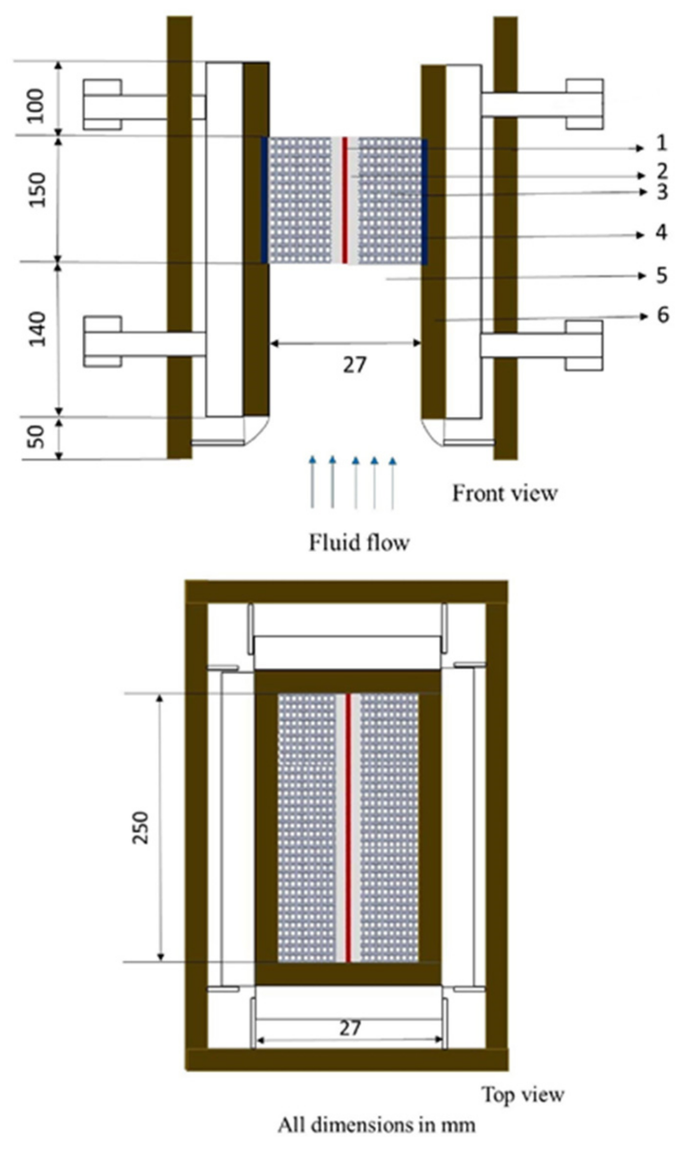
2. Problem Statement

With knowledge of the significance of morphological parameters of porous media in the numerical modeling of flow and heat transfer, cross relations for evaluating morphological parameters such as porosity, specific surface area of stacked brass wire-mesh porous media are arrived at for various stacking types with the help of easily available information such as fiber diameter (df) and pitch (dp) of the woven mesh screen. Generalized expressions for screen spacing (h) for the closely packed scenario under various stacking scenarios are obtained and identified. With the aid of the arrived expressions, such stacked wire-mesh samples are categorized based on orderly varying porosity and pore- density/mesh-size combinations, and the respective heat transfer and flow influencing parameters are evaluated, thereby allowing the numerical modeling of the categorized porous samples for analyzing their thermal performance.
With the aid of the arrived expressions, stacked wire-mesh samples of 0.8, 0.85, 0.9 and 0.95 porosity each with pore densities 5, 10, 15, 20, 30, 40 and 45 PPI (of woven wire-mesh screens) are categorized under three different stacking scenarios, namely, staggered, inline type-a and inline type-b. Such categorized porous samples are evaluated for thermal performance in a vertical channel subjected to a constant heat input of 20 W under laminar flow achieved with 0.25 m/s air velocity under steady state conditions. The thermal phenomena identified by the wall heat transfer coefficient are analyzed for the categorized wire-mesh porous samples. Temperature information is numerically obtained; the excess temperature of the vertical plate is calculated using Equation (2) and is then used to compute the wall heat transfer coefficient using Equation (1).
The heat transfer coefficient is given by:
h w a l l = Q A T w
where,
T w = T T a v g

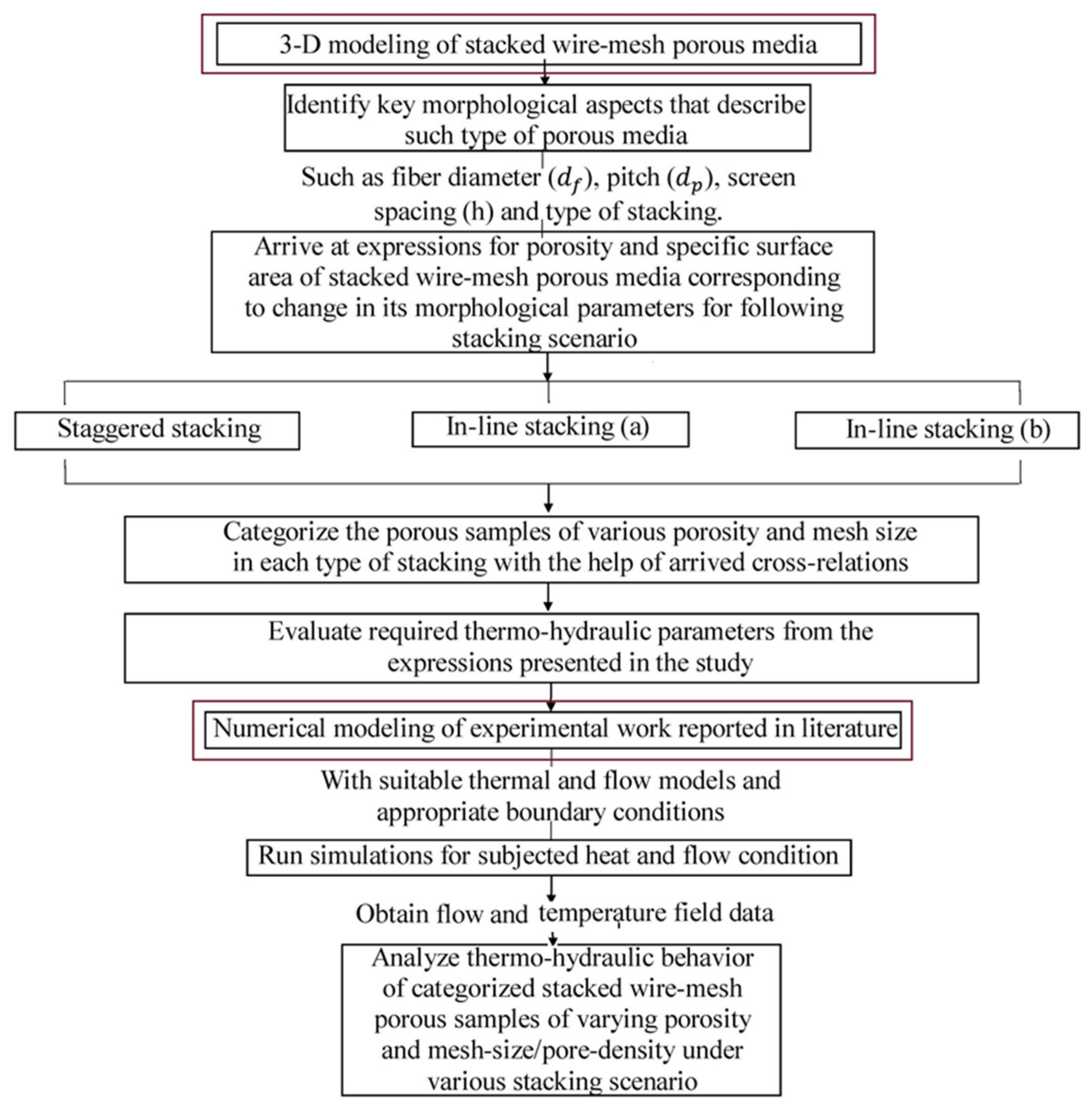
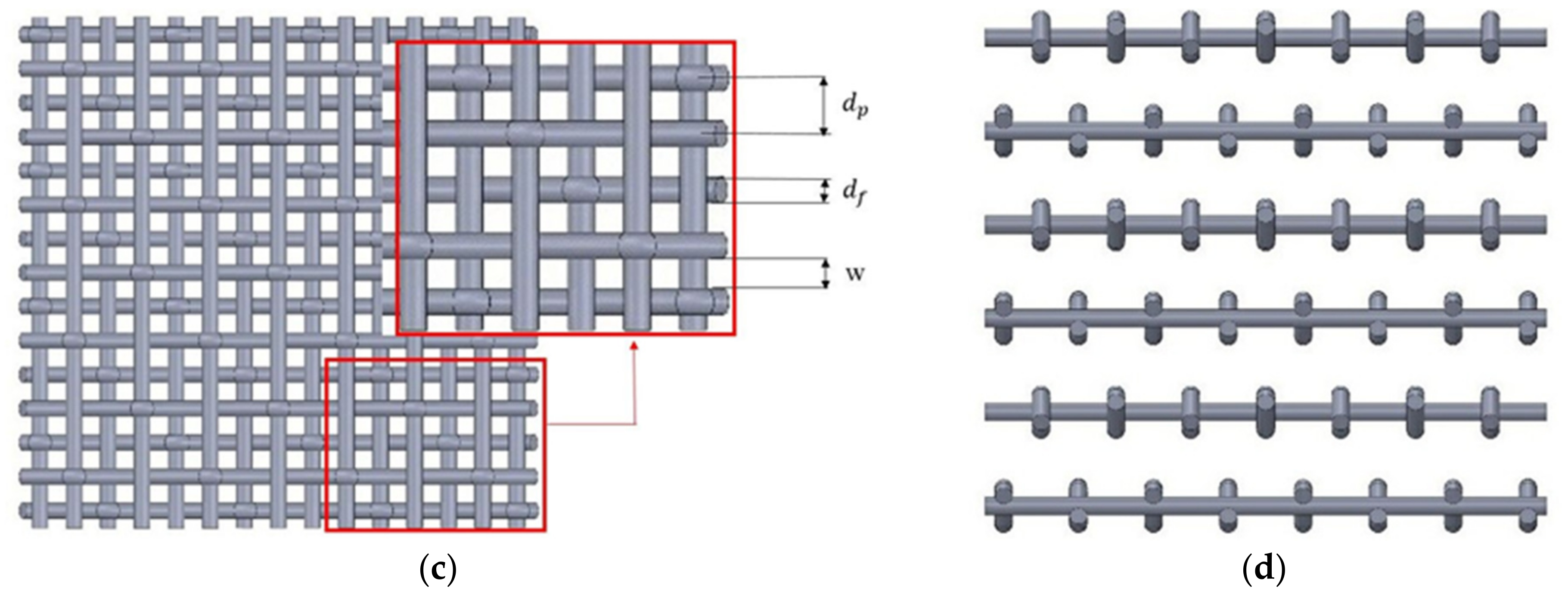
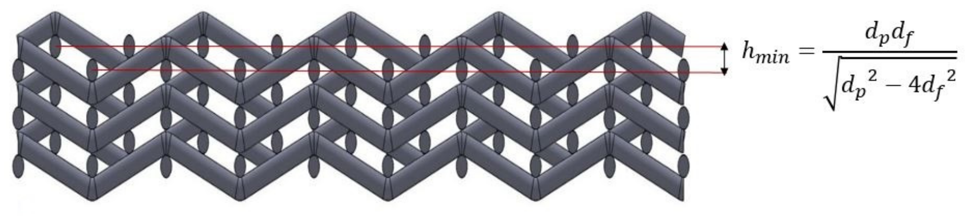
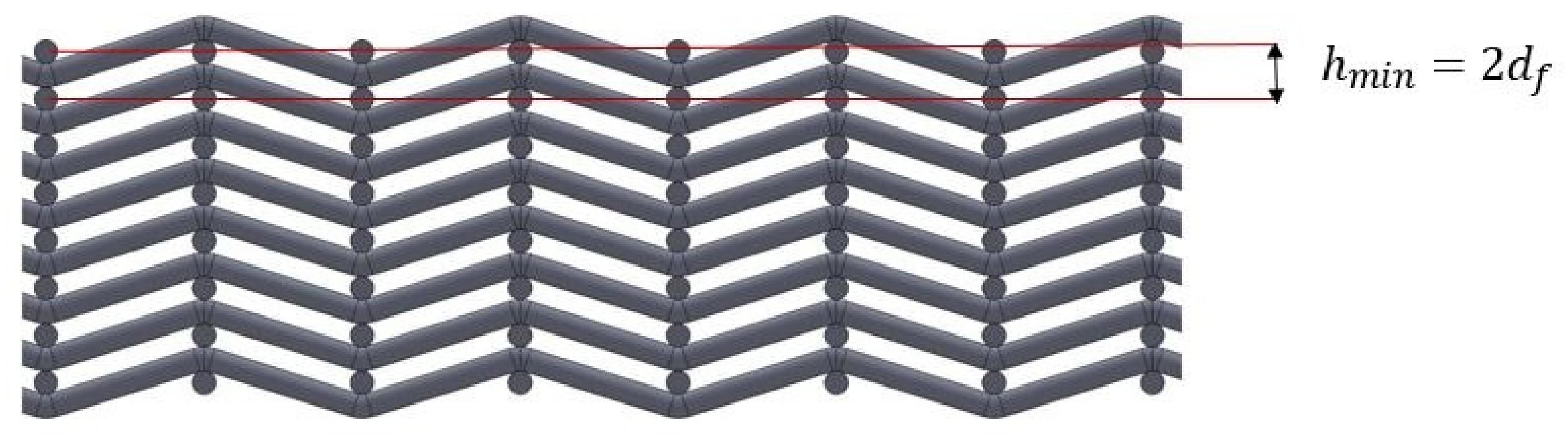
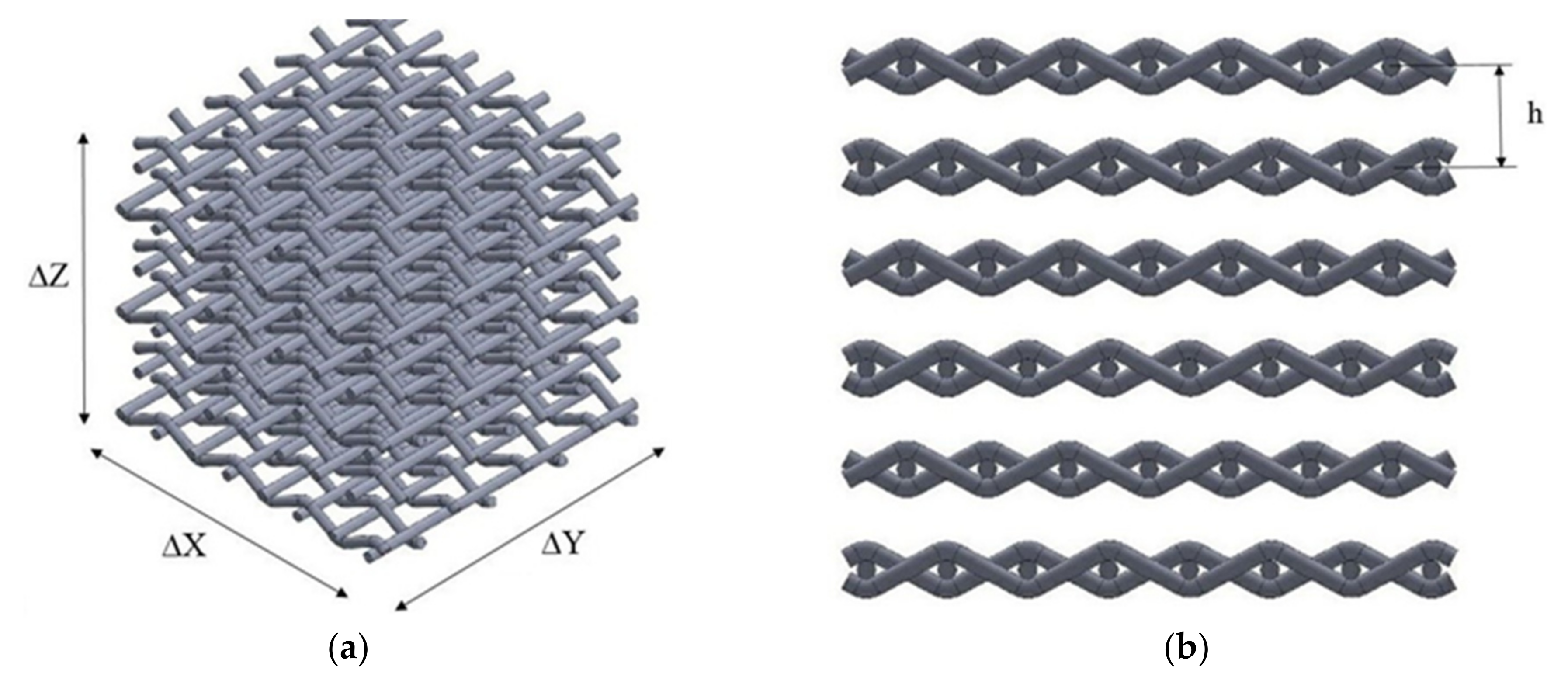
3. Modeling and Arriving at Expressions for Stacked Woven Wire-Mesh Porous Samples

A cube of size ∆X × ∆ × ∆ is adopted within which the whole fluid saturated woven wire-mesh samples are geometrically modelled. The straight cylindrical wires are drawn in the Y direction and the curved woven wires are woven in the X direction along the length of the straight cylindrical wires. Woven wire mesh screens thus obtained are arranged in the Z direction to obtain a block of stacked woven wire mesh screens forming a fluid (empty spaces) saturated wire-mesh porous medium. Various views of the obtained geometry of the considering wire-mesh blocks are shown in Figure 2a–d. The front view of wire mesh layers of staggered, inline type-a and inline type-b stacking under the closely packed scenario are shown in Figure 3, Figure 4 and Figure 5.

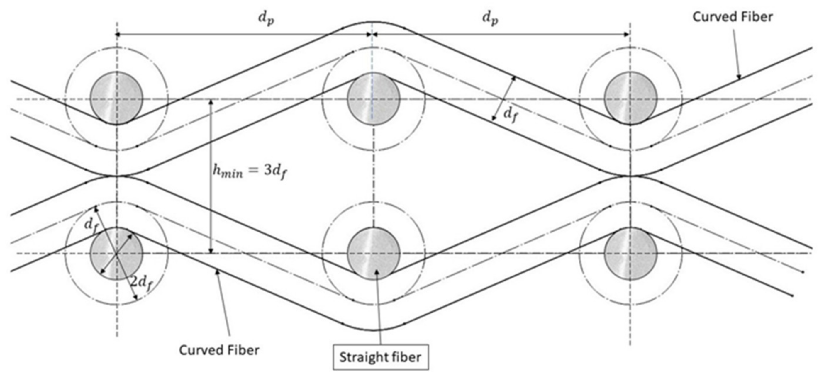
3.1. Determination of Interstitial Area Density or Specific Area

By definition [31], the interstitial area density or specific area (asf) is determined as follows:
a s f = T o t a l   s u r f a c e   a r e a   o f   w i r e m e s h a l   v o l u m e   o f   t h e   w h o l e   b l o c k   e n t i r e   f l u i d   s a t u r a t e d   w i r e m e s h   b l o c k
where, the dimension of the cube comprising fluid saturated woven wire-mesh porous media is represented as, ∆X × ∆ × ∆.
Referring to Figure 2a, the number of woven wire-mesh screens (n) can be expressed as shown in Equation (4), where ‘h’ is the distance between two consecutive mesh layers measured from center to center of straight running,
n = Z h
It can be observed from Figure 2a that each layer of the wire-mesh block is formed by weaving cylindrical wires onto those cylindrical wires passing straight in the perpendicular direction. Therefore, the total surface area of the wires forming each layer of the wire-mesh block can be put in the following form.
The total surface area of each mesh layer (a1) is the sum of the product of (a) the area of straight running cylindrical wire (as) and the total number of straight running cylindrical wires (Ns) and (b) the area of the weaving cylindrical wire (aw) and the total number of weaving cylindrical wires (Nw), which can be expressed as:
a 1 = a s × N s + a w × N w
Observing Equations (4) and (5), the total area of the solid cylindrical wires forming the whole mesh block (Asm) can be expressed as:
A s m = a s × N s + a w × N w × Z h
Now, the parameters appearing in Equation (6) can individually be expressed as follows:
N s = X d p
N w = Y d p
a s = π d f Y + π 2 d f 2
a w = π d f L + π 2 d f 2
The parameter ‘L’ appearing in Equation (10) is the length of the weaving wire, where its value can be expressed from observing Figure 6a,b as:
L = O D × n u m b e r   o f   p o r e s   a s   t h e r e   e x i s t s   a   c u r v e   O D   i n   e v e r y   p o r e
OD: as shown in Figure 6b.
The expression for the number of pores can be approximated as
N p = N s = X d p
In Equation (11), in order to find the expression for length ‘L’, the expression for ‘OD’ is derived and multiplied by the number of pores. For that, observing Figure 6a, angle AO’B can be expressed as:
C o s θ = O A O B = 2 d f d p
θ = c o s 1 2 d f d p
Therefore, angle
A O O = π 2 θ
Length of arc
O A = d f π 2 θ
Considering A O B ,
A B 2 = O B 2 A O 2
Therefore,
A B = d p 2 4 d f 2
However, the length OD = OA + AB + BC + CD, but OA = CD, which yields,
O D = 2 O A + A B
Therefore the above equation for the length ‘OD’ can be rewritten, from expressions for ‘OA’ and ‘AB’ as given in Equations (16) and (18) as,
O D = 2 d f π 2 θ + d p 2 4 d f 2
Inserting expression for θ as given in Equation (14), we get,
O D = π d f 2 d f c o s 1 2 d f d p + 2 d p 2 4 d f 2
From Equations (12) and (21) length of each woven wire can be obtained as,
L = X d p π d f 2 d f c o s 1 2 d f d p + 2 d p 2 4 d f 2
Therefore, the obtained expression for ‘L’ can be used in Equation (10). Now, the expression for total area of solid cylindrical wires both straight passing as well as weaving ones as expressed in Equation (6), can be rewritten by referring to Equations (4) and (8)–(10) as
A s m = π d f Y + π 2 d f 2 X d p + π d f X d p π d f 2 d f c o s 1 2 d f d p + 2 d p 2 4 d f 2 + π 2 d f 2 Y d p Z h
Interstitial area density or specific surface area is expressed as,
a s f = A s m X Y Z
Therefore, from Equation (23), the expression for ‘asf’ (for a woven-mesh block of spacing “h”) can be deduced by simplification as
a s f = A s m X Y Z = π d f h d p 1 + d f d p π 2 C o s 1 2 d f d p + 1 2 d f d p 2 + d f 2 1 Δ X + 1 Δ Y
Since term d f 2 1 Δ X + 1 Δ Y yields are of very negligible value, the above expressions can be simplified by neglecting this term as
α s f = π d f h d p 1 + d f d p π 2 C o s 1 2 d f d p + 1 2 d f d p 2
By taking d f d p = k , the above equation can be rewritten as
α s f = π k h 1 + k π 2 k C o s 1 2 k + 1 4 k 2
Stacking of the wire-mesh layers can be made in three different ways that include staggered stacking as shown in Figure 3, inline type-a as shown in Figure 4 and inline type-b as shown in Figure 5. For the closely packed scenario, the value of ‘hmin’ varies with type of stacking. For the staggered type, it is difficult to be interpreted by mere observation and the same is expressed mathematically in the following way. The upper layer of the woven mesh screen rests on the lower layer as shown in Figure 7. It can be observed in Figure 7 that the length of ‘OC’ is the minimum spacing ‘hmin’ for the closely packed wire-mesh block scenario for staggered type of stacking. The expression for ‘hmin’ with reference to the Figure 7 can be obtained as follows:
Let O C = A C = h m i n ; thenb, we know that from A O B
c o s = 2 d f d p
In addition, from O B C ,
s i n = d f h m i n
From the trigonometric relation c o s 2 + s i n 2 = 1 ,   the above equations can be written as
4 d f 2 d p 2 + d f 2 h m i n 2 = 1
h m i n = d p d f d p 2 4 d f 2
Hence, for the closely packed woven wire-mesh scenario for the staggered stacking type, the expression for h m i n as given in Equation (31) can be used in Equation (25) for obtaining the corresponding value of the specific surface area. A detailed sketch of the inline type-a and type-b stacking scenarios is shown in Figure 8 and Figure 9 following which expressions h m i n = 2 d f and h m i n = 3 d f can be used in Equation (25) for obtaining the specific surface area of the wire-mesh porous medium of inline type-a and inline type-b stacking, respectively.

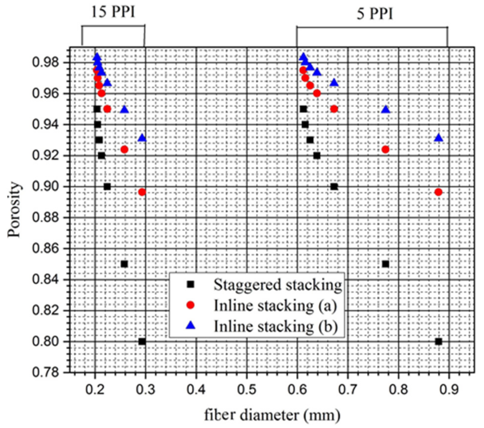
3.2. Cross-Relations between Porosity, Fiber Diameter and Pore Width

Cross-relationships between morphological characteristic of wire-mesh layers such as fiber diameter and pore width and characteristics of stacked wire-mesh porous structures such as porosity would serve a great purpose by making it easier to avail information on unknown parameters that are difficult to evaluate (for instance, porosity and specific surface area that depend on several other parameters such as stacking manner, fiber diameter and pitch) with information on easily distinguishable parameters. The procedure for arriving at such cross-relations is mentioned below.
The volume of the solid woven mesh layer can be written analogously to Equation (5) as
v 1 = ( v s × N s ) + v w × N w
The total volume of the solid cylindrical wires (both woven as well as straight running) forming the mesh block can therefore be written as
V s m = n ( v s × N s + v w × N w )
The volume of a single straight running cylindrical wire can be expressed as
v s = π d f 2 Y 4
Similarly, the volume of the weaving cylindrical wire can be expressed as
v w = π d f 2 L 4
Porosity is defined as [31]:
P o r o s i t y = T o t a l   v o l u m e   o f   t h e   v o i d   s p a c e   f l u i d   r e g i o n   T o t a l   v o l u m e   o f   t h e   w h o l e   b l o c k   c o m p r i s i n g   o f   t h e   f l u i d   s a t u r a t e d   p o r o u s   m e d i u m  
which in this case can be written as
ε = V V s m V
1 ε = V s m V
where, ‘V’ is total volume of the whole fluid saturated porous mesh block expressed as ΔXΔY ΔZ.
From, Equations (4), (22) and (33)–(35), Vsm/V can be expressed as,
V s m V = π d f 2 4 h d p 1 + 1 d p π d f 2 d f C o s 1 2 d f d p + d p 2 4 d f 2
Comparing Equations (38) and (39), the expression for porosity for a woven wire-mesh block with spacing ‘h’ between the mesh layers can be written as
ε = 1 π d f 2 4 h d p 1 + 1 d p π d f 2 d f C o s 1 2 d f d p + d p 2 4 d f 2
For closely packed woven wire-mesh blocks of staggered type, the expression for porosity can be obtained by incorporating the expression for ‘hmin’ given in Equation (31) in Equation (40) as
ε s t a g g e r e d = 1 π d f d p 2 4 d f 2 4 d p 2 1 + 1 d p π d f 2 d f C o s 1 2 d f d p + d p 2 4 d f 2
Taking
d f d p = k
Equation (41) can be rewritten as
ε s t a g g e r e d = 1 k π 4 1 4 k 2   1 + k π 2 k C o s 1 2 k + 1 4 k 2
valid for 0 k 0.5 .
For the closely packed woven wire-mesh blocks of inline type-a and inline type-b stacking scenarios, the expression for porosity can be obtained by incorporating expression for ‘hmin’ equal to 2df in Equation (40), which for inline stacking of type-a becomes
ε I n l i n e t y p e a = 1 π d f 2 4 2 d f d p 1 + 1 d p π d f 2 d f C o s 1 2 d f d p + d p 2 4 d f 2
ε I n l i n e t y p e a = 1 π d f 8 d p 1 + π d f d p 2 d f d p C o s 1 2 d f d p + 1 2 d f d p 2
ε I n l i n e t y p e a = 1 k π 8   1 + k π 2 k C o s 1 2 k + 1 4 k 2
Similarly, for the stacking of inline type-b, the incorporating expression for ‘hmin’ equal to 3df generalized expression for porosity becomes
ε I n l i n e t y p e b = 1 π d f 2 4 3 d f d p 1 + 1 d p π d f 2 d f C o s 1 2 d f d p + d p 2 4 d f 2
ε I n l i n e t y p e b = 1 π d f 12 d p 1 + π d f d p 2 d f d p C o s 1 2 d f d p + 1 2 d f d p 2
ε I n l i n e t y p e b = 1 k π 12   1 + k π 2 k C o s 1 2 k + 1 4 k 2
For various values of ‘k’ in the range of 0 k 0.5 , fitting a polynomial curve with R 2 value 0.99866, 0.99963 and 0.99933 for staggered, inline type-a and inline type-b stacking scenarios and considering 501 data points obtained from the above equation provides a compact equation expressing the porosity of woven wire-mesh for the mentioned stacking types as a function of only two morphological properties (fiber diameter and pore-density/mesh-size) of the wire-mesh, which can be obtained as
ε s t a g g e r e d = 1.01051 1.87112 k + 1.60829 k 2
ε I n l i n e t y p e a = 0.99358 0.63809 k 0.68232 k 2
ε s t a g g e r e d = 0.99572 0.42539 k + 0.45488 k 2

3.3. Interstitial Heat Transfer and Flow Resistance Coefficients

In modeling any type of porous media with the LTNE approach, as can be seen in Equation (61), information on interstitial heat transfer coefficient hsf is crucial in solving the energy equation. An effort to identify suitable correlations for the interstitial heat transfer coefficient can be witnessed in a study by Kotresha and Gnanasekaran [30]; the study was focused on determining the interstitial heat transfer coefficient based on correlations that were available in the literature for the packed- bed scenario [32], cross-flow through cylinders [33] and for the situation with metal foam. The study showed that the thermal phenomenon assessed (the wall heat transfer co-efficient of vertical channel) was relatively in good argument with experimental data when the interstitial heat transfer coefficient as provided by Calmidi and Mahajan [34] was used in numerical modeling. The suitability of the correlation was upheld on relative deviation of the thermal phenomenon expressed based on results obtained when the interstitial heat transfer coefficient was evaluated with respective to the correlation considered. However, in a recent study, Garg et al. [21] successfully modeled a regenerator with the wire-mesh porous modeling method by using the interstitial heat transfer coefficient obtained from relation provided by [23]. In the present study, the same relation provided by [9] as given in Equation (53) is used to the evaluate interstitial heat transfer coefficient and the thermal phenomenon expressed through numerical modeling using this relation is compared with that of experimental data in order to emphasize the suitability of this correlation. Figure 10 shows the comparison of the thermal phenomenon characterized by wall heat transfer co-efficient of the vertical channel of present numerical work to that of experimental work of Kurian et al. [28]. Good agreement in the thermal phenomenon can be witnessed here as a result of the incorporation of the interstitial heat transfer co-efficient evaluated from the relation provided by [23] to solve the energy equation. Thus, for further analysis, evaluation of the interstitial heat transfer co-efficient is carried out based on the relation provided by [23], as emphasized by [21].
The inertial and viscous resistance co-coefficients are another set of important parameters that are vital in modeling wire-mesh porous media using the Darcy-Forchheimer model. For the steady state case, Xiao et al. [9] provided the expressions for calculating these parameters by referring to friction factor expressions provided by Tanaka et al. [35] and the modified-Ergun equation provided by Gedeon and Wood [36]. The obtained relations were compared with the pressure drop as described by the Darcy-Forchheimer law and expressions for the viscous and inertial resistance coefficients were provided as given in Equations (54) and (55) respectively. It can be observed that these flow parameters are functions of both porosity as well as fiber diameter and rightly predicts flow resistance in the considered wire-mesh type of porous medium. Hence, these expressions are used for evaluating viscous and inertial resistance coefficients required for modeling the flow phenomenon in the considered wire-mesh porous media.
h s f = λ f 1 + 0.99 R e d h P r 0.66 ε 1.79 d h
1 K = 134 2 ε d h 2
C = 5.44 ε 2 d h R e d h 0.188

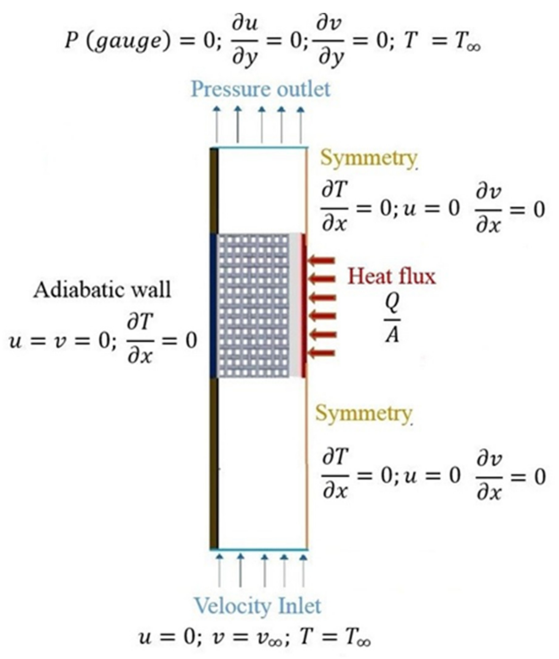
4. Numerical Simulation, Boundary Conditions, Computational Scheme and Governing Equations

For this purpose, the experimental set-up of Kurian et al. [28] to investigate stacked wire-mesh porous media is numerically modelled using commercial ANSYS FLUENT software. The sketch of the experimental set up used by Kurian et al. [28] is shown in Figure 11. However, for numerical modeling, due to the symmetric nature of the experimental domain, only one of the symmetric portions is considered for numerical modeling with the help of the symmetry boundary conditions. A sketch of the numerical domain of the present study with boundary conditions is shown in Figure 12.
Appropriate boundary conditions are incorporated in the present numerical domain as shown in Figure 12. Channel walls are given by adiabatic boundary conditions with no slip conditions established at the fluid-wall interface. Continuity in energy and momentum is considered at dissimilar contact regions among solid, fluid and porous zone interfaces. The velocity inlet boundary condition at inlet and pressure outlet boundary condition at outlet are specified. The heat flux boundary condition is specified in the heater region.
Momentum and continuity equations are solved in a coupled fashion by employing a pressure based coupled algorithm (COUPLED scheme) available in ANSYS FLUENT [37]. A second order upwind scheme is used for spatial discretization. As it is known, using the upwind discretization scheme, the values at upstream are used to compute the value on the faces of the cell and then used to evaluate the value at the center of the cell. The first order upwind scheme uses one point at the upstream to compute the values at cell faces and cell center whereas, the second order uses two points at the upstream for computation. Though the first order upwind scheme is most commonly used as it is easier to converge in complex domains, the second order upwind scheme is more accurate than the first order scheme; however, this could present difficulty in convergence in complex problems. Since the present study involves a less complicated 2D flow and heat transfer domain, the second order upwind scheme is used to provide more accurate results (in comparison with the first order upwind scheme) with no difficulty in convergence. Gradients are obtained through the Green-Gauss node-based method. To help ease the convergence, implicit relaxation with the pseudo-transient method is implemented. Convergence criteria are set to 10−5 for momentum and continuity equations and for the energy equation, it is set to 10−10 for higher accuracy. The outcome of the mesh independence study is shown in Table 1. A mesh with 56,700 cells resulted in the least percentage deviation in pressure drop and excess temperature values. Therefore, further numerical simulations are carried out by adopting the developed numerical domain with 56,700 cells.
The governing equations solved to obtain flow and heat transfer parameters in the wire-mesh-free region are given by Equations (56)–(58).
Continuity equation:
ρ f u i x i = 0
Momentum equation:
ρ f u i u j x j = p x j + x j μ f u i x j + u j x i
Energy equation for fluid:
ρ f C p f u j T x j = x j ( λ f T f x j )
In the aluminum plate region, λs(∇2T) = 0 is solved for heat transfer through conduction to take place. Furthermore, the governing equations pertaining to the wire-mesh-filled region are given in Equations (59)–(62). Flow and heat transfer influencing parameters of stacked wire-mesh porous media such as porosity, specific surface area, thermal conductivity, etc. can be observed to be well considered in the governing equations. The source term in the momentum equation given in Equation (60) can be seen to incorporate terms representing viscous and inertial effects fluid experiences while passing through the considered wire-mesh porous medium.
Continuity equation:
ρ f ε u i x i = 0
Momentum equation:
ρ f u i u j x j = ε p x j     x j μ f u i x i + u j x j ε ( μ e f f K u i + ρ f C u u i )
LTNE equation for fluid,
ε   ρ f C p f u j T x j = λ f e ε x j ( T f x j ) + h s f a s f ( T s T f )
for solid,
λ s e 1 ε x j ( T s x j ) = h s f a s f ( T s T f )
where
λ f e = λ f .   ε   and   λ s e = λ s   .   1 ε

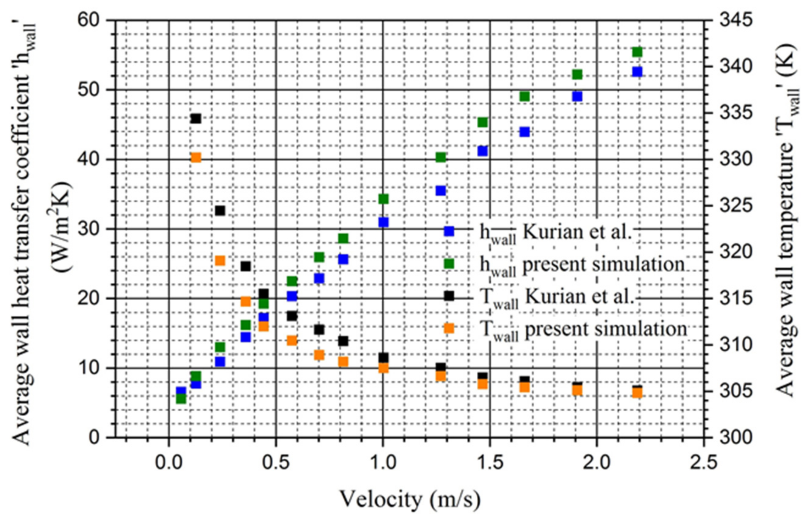
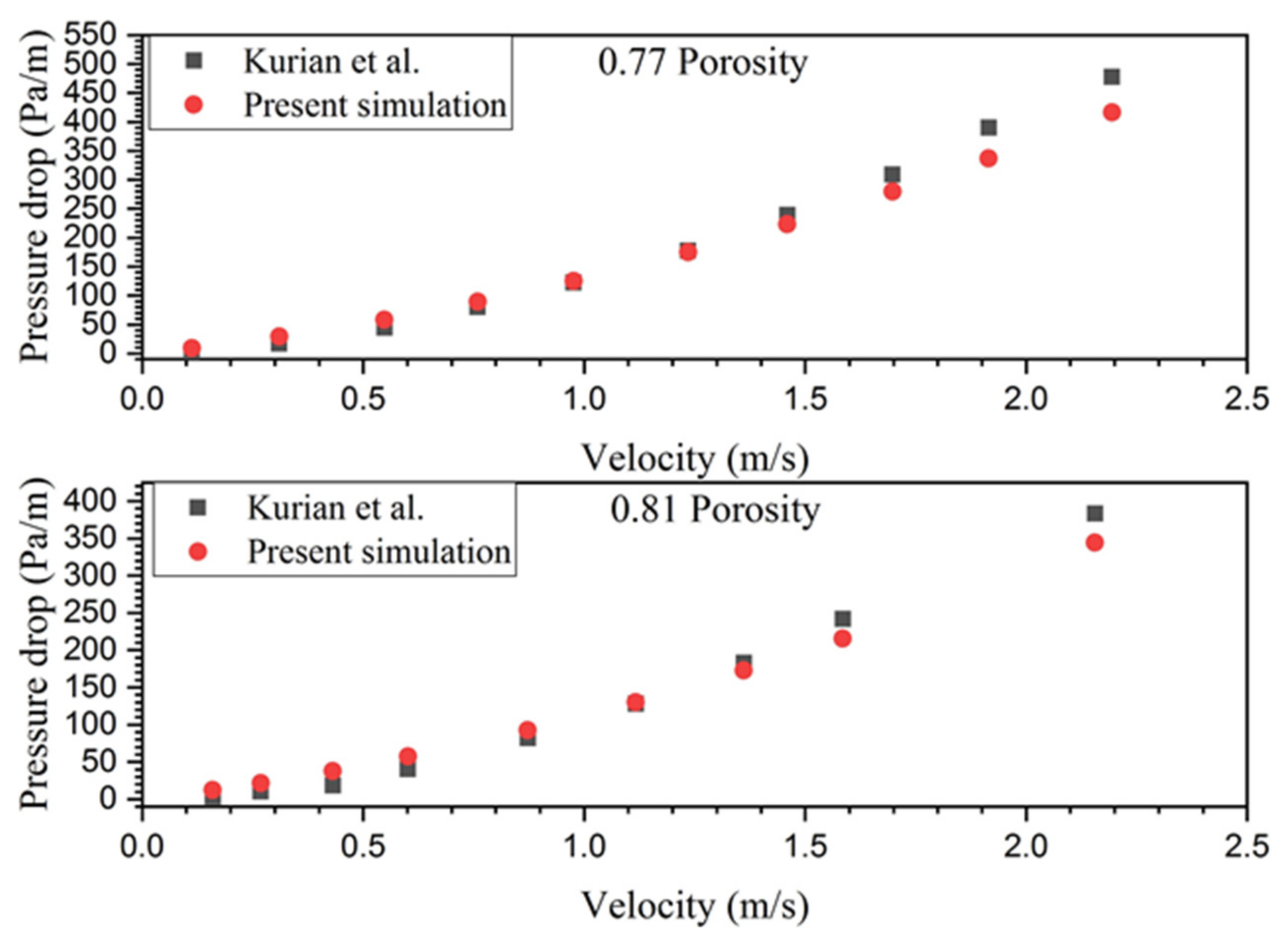
Validation of the Numerical Solution

The simulated results from the modeled numerical domain are compared with that of experimental data of Kurian et al. [28] for validation of the followed modeling methodology. From Figure 10, a good agreement between the average wall heat transfer coefficient and average wall temperature obtained through present numerical simulation and experimental results reported in the literature can be observed. An average difference of 4.2 W/m2 K with a maximum and minimum difference of 5.13 W/m2 K and 0.973 W/m2 K, respectively, is observed between wall heat transfer coefficients. In terms of deviation between experimentally measured temperature and numerically simulated temperature data, an average percentage deviation of less than 0.79 percent is observed, with highest and lowest deviations of 1.65 percent and 0.09 percent, respectively. This demonstrates the correctness and suitability of the followed methodology in order to mimic heat transfer in the considered type of porous medium. In terms of flow phenomenon, variation of experimentally measured and numerically obtained pressure drop with velocity is shown in Figure 13. A good agreement between present numerically obtained data and experimentally reported data is observed with 6 percent and 8 percent average percentage deviations for the 0.71 and 0.81 porosity wire-mesh stack, respectively. Thus, the followed methodology for mimicking flow and heat transfer numerically can be seen to be appropriate for further analysis.

5. Results and Discussion

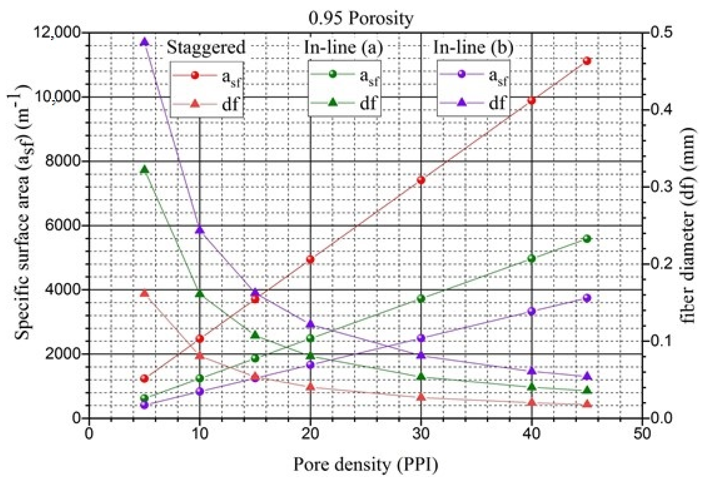
5.1. Interpretation of Results from the Expressions Arrived

The expressions arrived at in the present study that enable the obtaining of vital morphological properties that play a key role in the thermo-hydraulic performance of stacked woven wire-mesh porous media are interpreted in this section. The present study provides cross relations between important parameters such as pore density/mesh size of the wire-mesh screen (mesh per inch/PPI) used in stacking, fiber diameter (df) of the wires used to weave the mesh screen, porosity and specific surface area of the stacked wire-mesh blocks corresponding to the three various kinds of stacking such as staggered, inline type-a and inline type-b. It can be noted that from the expressions provided in the present study, porosity and specific surface area, which play a prominent role in momentum and energy equations, can be evaluated with the knowledge of only fiber diameter (df) and pitch (dp) of wire-mesh screens used for various stacking conditions. Thus, porous media of various characteristics that can be obtained by changing the fiber diameter and pitch of the woven screens for various stacking conditions can easily be studied using porous media formulation in a variety of applications in order to arrive at the optimum thermo-hydraulic behavior of such types of porous media.
The variation of porosity of the stacked wire-mesh porous blocks with respect to change in fiber diameter for various type of stacking and pore-density/mesh size is shown in Figure 14; for better visual observation, the variation of porosity and fiber diameter of only 15 PPI and 5 PPI randomly chosen mesh-size samples. However, the respective changes for other pore densities are also observed to follow a similar trend. It can be observed that for any type of stacking of wire-mesh screens of given mesh size (PPI/mesh per inch), porosity decreases with increase in fiber diameter as expected. The magnitude of variation in porosity with change in fiber diameter is relatively high for staggered stacking, followed by inline stacking type-a and type-b. For a given fiber diameter, a stacked block of high porosity can be achieved with inline stacking type-a, followed by inline stacking type-b and staggered stacking. In addition, it can be observed that with increase in fiber diameter, a fixed porosity can be achieved by decreasing the mesh size (MPI) or pore density (PPI). The present study enables numerical study of various stacked wire-mesh porous samples subjected to change in its morphological parameters and stacking condition by providing information on the hydro-dynamic parameters of corresponding stacked wire-mesh porous samples.
The variation of specific surface area of stacked wire-mesh porous media for various stacking conditions is shown in Figure 15; the variations are discussed by depicting randomly chosen 0.95 porosity foam samples. However, the variations show a similar trend for any other porosity case. It can be observed that for a given porosity, specific surface area increases with increase in mesh size or pore density of the stacked screens for all type of stacking; however, it is dominated by the staggered type of stacking, followed by inline type-a and type-b kinds of stacking. In addition, it has to be noted that a fixed porosity can be achieved for the considered different kinds of stacking with a compromise in the fiber diameter of weaved wires. Staggered type of stacking provides the required porosity for a given mesh size (PPI/MPI) at lesser fiber diameter compared to inline stacking of type-b and type-a scenarios for same porosity at a given mesh size or pore density condition.

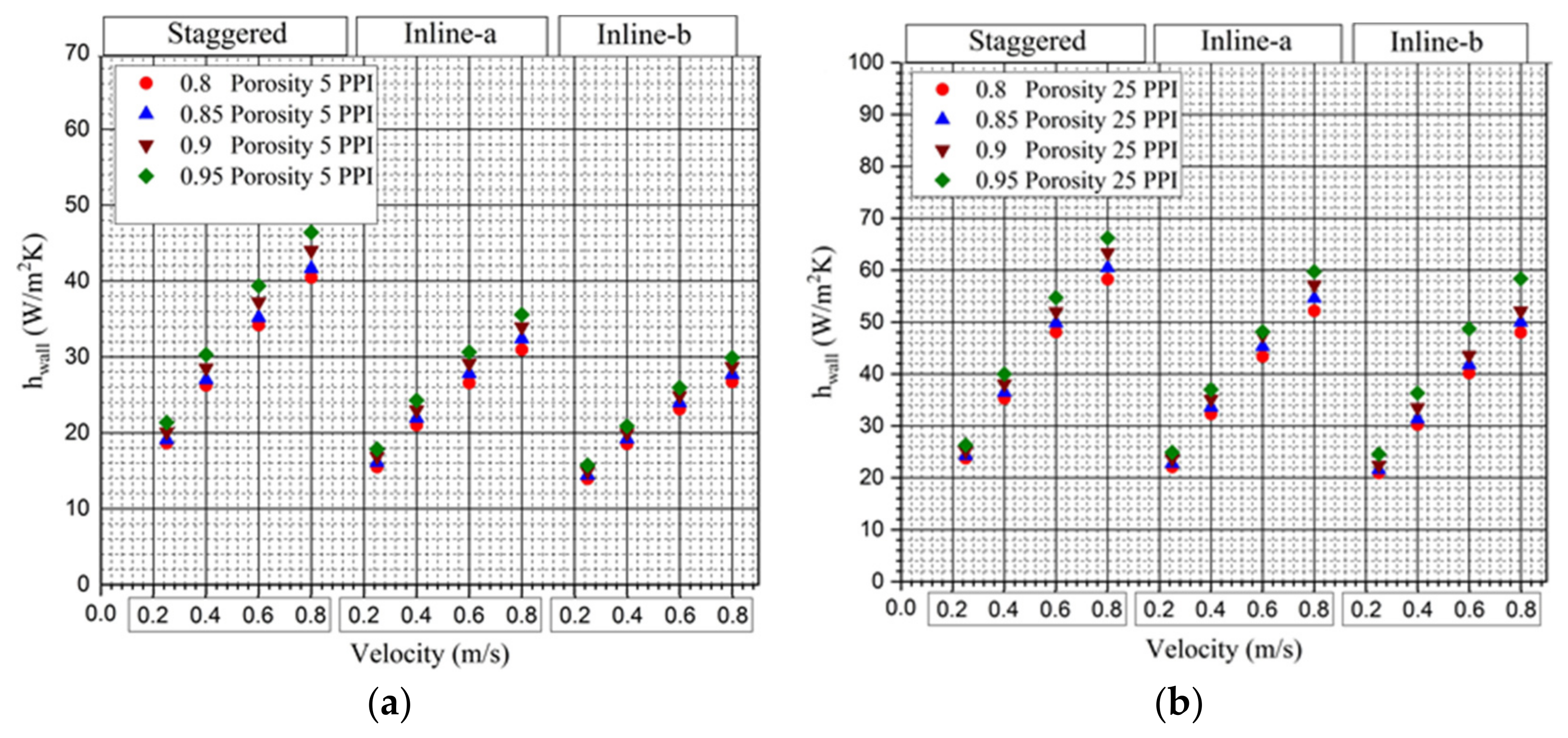
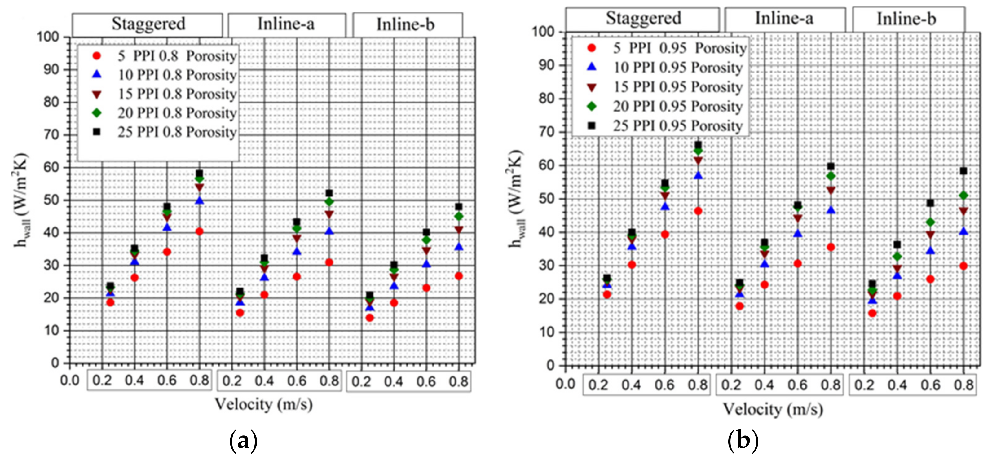
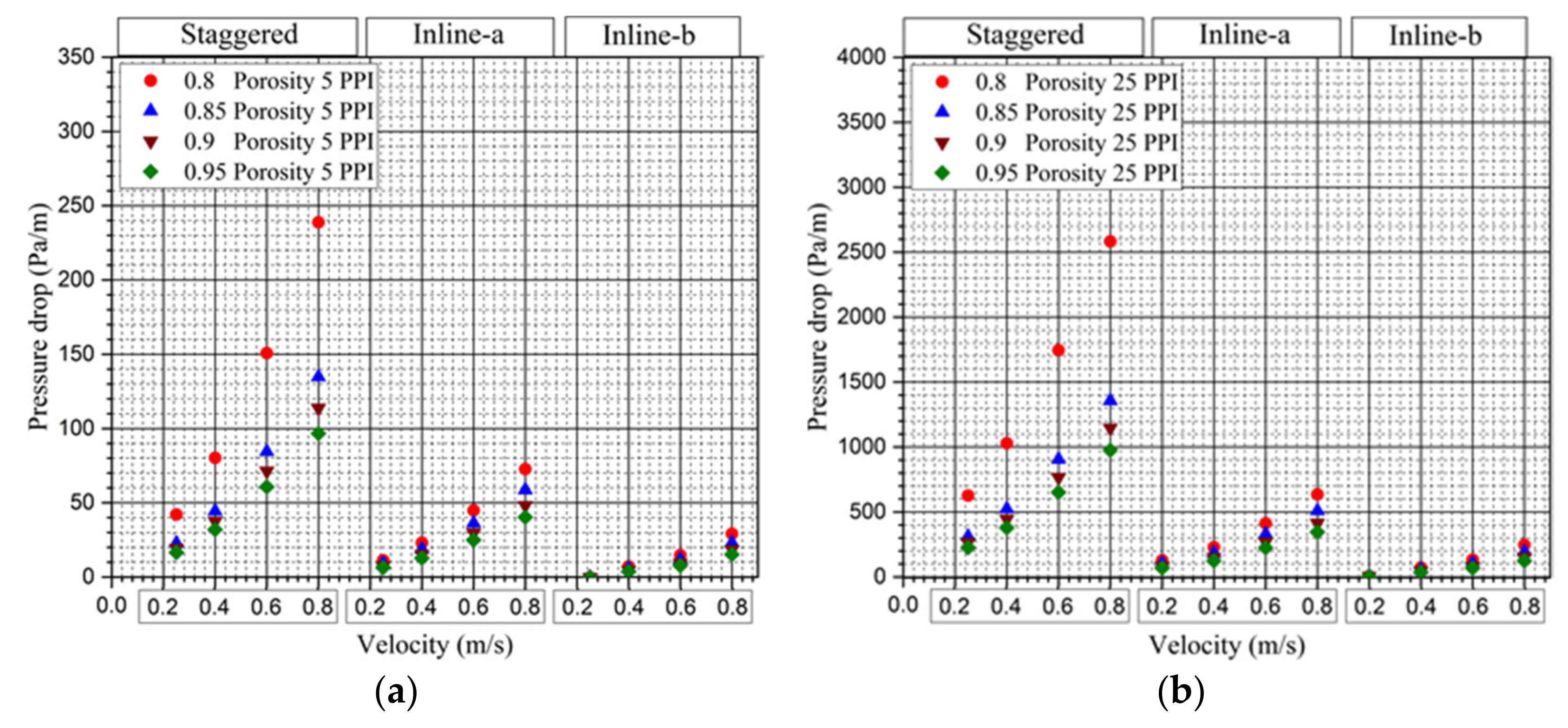
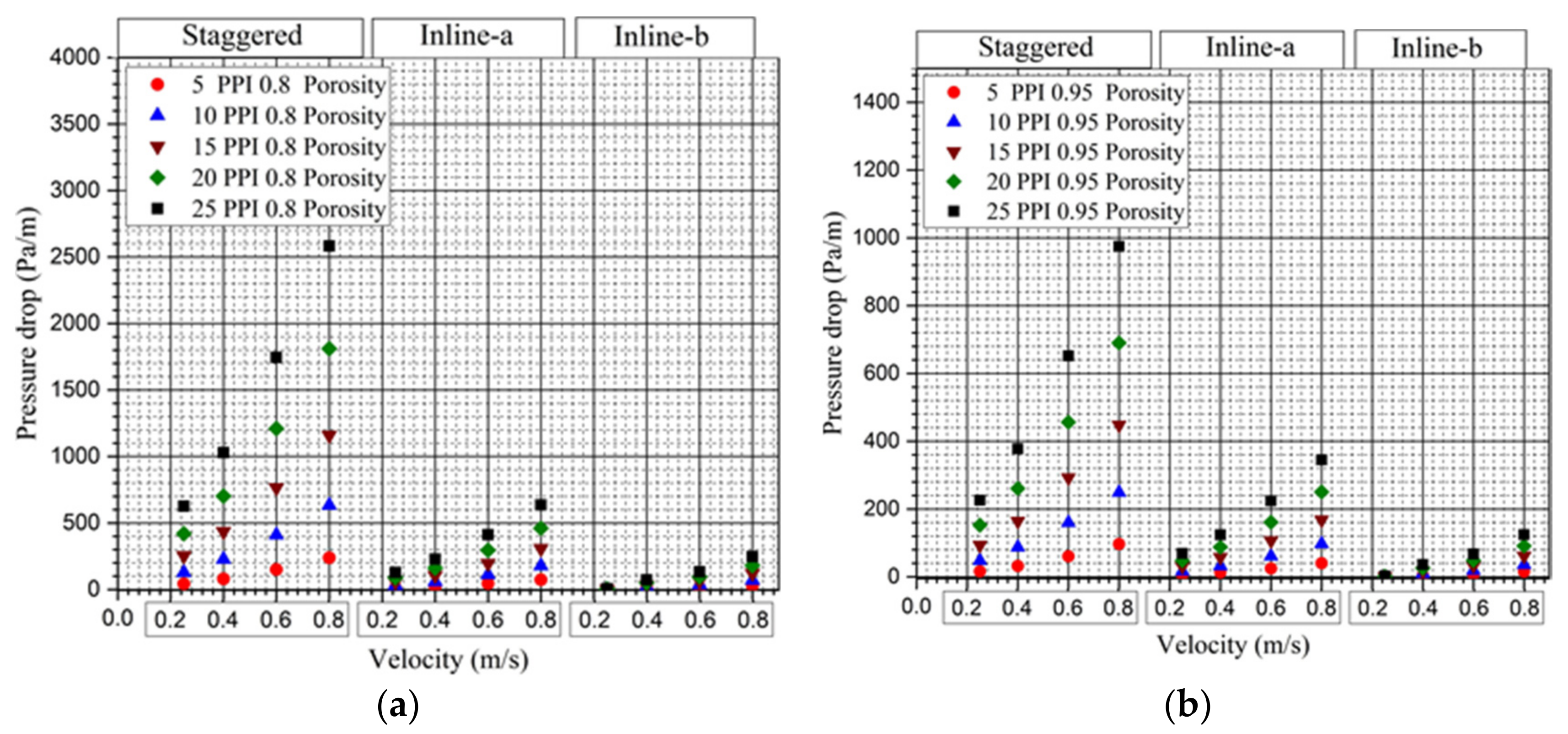
5.2. Thermo-Hydraulic Analysis

As explained in Section 2, with the aid of the arrived expressions, stacks of woven wire-mesh samples of orderly varying porosity (0.8, 0.85, 0.9 and 0.95) for each stack of woven wire-mesh screens of 5, 10, 15, 20, and 25 PPI pore-densities/mesh-sizes were obtained. It can be noted that for a given pore density of wire-mesh screens, stacks of various porosity can be achieved by changing the fiber diameter of the wires that form the mesh screens. For the categorized stacks of woven wire mesh screens, specific area (asf) and porosity (s) are evaluated based on expressions arrived at in the present study as given by Equations (27) and (50)–(52) for considered stacking scenarios. The vertical channel numerical domain as described in Section 2 is modelled with these categorized stacked wire-mesh porous samples. With the subjected heat flux and flow velocities, the thermal performance of the categorized porous samples (based on changes in mesh-size/pore-density and porosity) is shown in Figure 16a and Figure 17b (Figure 18 and Figure 19) in terms of wall heat transfer coefficients for all stacking scenarios. The variation of this thermal phenomenon is demonstrated with the variation in porosity for a constant pore-density/mesh-size (PPI/MPI), as shown in Figure 16a (for 5 PPI/MPI) and Figure 16b (for 25 PPI/MPI). Similarly, variation of the same phenomenon with change in pore-density/mesh-size for a constant porosity can be seen in Figure 17a (for 0.8 porosity) and 17b (for 0.95 porosity). It can be observed that the wall heat transfer co-efficient increases with increase in both pore density as well as porosity. However, for a stack of given porosity, heat transfer greatly increases with pore density compared to the increase of the same parameter with an increase in porosity for a stack of given pore density. In LTNE modeling, the total heat transfer is accounted for by heat transfer due to fluid (this increases with porosity) and interstitial heat transfer (this increases with increase in the product asf × hsf) [8]. As a result, for a given pore density, the wall heat transfer coefficient increases with porosity due to enhanced availability of fluid to carry the subjected heat. Enhanced heat transfer is also witnessed with increase in pore density for a stack of given porosity, as a result of increased interstitial heat transfer (contributed by the product asf × hsf). The variation in the wall heat transfer coefficient is observed to be similar, corresponding to changes in porosity and mesh size for all types of stacking. However, for the same porosity and mesh size conditions, the relative deviation of the wall heat transfer of wire-mesh porous media formed by various stacking types is observed to show significant variation. This is mainly due to the increased specific surface area of staggered type for a given porosity, enabling higher heat transfer, followed by inline type-a and inline type-b, which have relatively lesser specific surface area for a given mesh-size/pore-density and porosity condition. As a result, interstitial heat transfer is increased for the staggered type compared to wire-mesh porous samples formed as a result of inline stacking of type-a and type-b conditions. In Figure 16a,b, the thermal performance is depicted for varying porosity condition for 5 PPI/MPI and 25 PPI/MPI mesh-size/pore-density situation only. However, the relative trend is observed to be the same for other 10 PPI/MPI and 15 PPI/MPI mesh-size/pore- densities of the considered wire mesh porous samples of various stacking scenarios. Similarly, in Figure 17a,b, though the variation of the thermal phenomenon is shown with reference to only 0.8 and 0.95 porosity samples, the relative deviation for other porosity conditions such as 0.85 and 0.9 porosity is observed to follow a similar trend. This implies that domination of heat transfer follows a similar trend for any other porosity and pore-density/mesh-size combinations for the considered different stacking scenarios, agreeing well with the explained reasons.
Flow resistance, characterized by the pressure drop phenomenon in the considered wire-mesh type of porous medium corresponding to mesh size and porosity of samples under various stacking scenarios, is shown in Figure 18a and Figure 19b. Variation of this phenomenon for wire mesh samples of various stacking conditions under varying porosities at constant mesh-size/pore-density is shown in Figure 18a,b. Similarly, variation of pressure drop for wire mesh samples of various stacking types under varying pore-densities/mesh-sizes at a constant porosity is depicted in Figure 19a,b. It can be observed that, for a given stacking scenario, the pressure drop decreases with increase in porosity for a given mesh size, as shown in Figure 18a,b. This is due to increased permeability of the fluid through the wire mesh structures with an increase in porosity. However, for a given porosity with an increase in mesh size, the pressure drop can be observed to be increasing due to increased obstruction to the flow with an increase in mesh-size/pore-density, as shown in Figure 19a,b. In terms of the stacking scenario, staggered stacking that offers low permeability to the fluid flow shows an increased pressure drop for a given porosity and mesh size, followed by inline stacking type-a and type-b. In addition, an increase in pressure drop is observed to be relatively more significant at higher mesh size than at lower mesh sizes. Though variation of flow resistance, characterized by the pressure drop for various stacking scenarios with changes in porosity is shown with reference to only 5 PPI/MPI pore-densities/mesh-sizes, the relative deviation is also observed to follow similar trends for 10 and 15 PPI/MPI wire-mesh samples. The argument is the same with reference to deviations of pressure drop with respect to change in pore-density/mesh-size. That is, though these deviations are shown with reference to only 0.8 and 0.85 porosity samples, the relative deviation is also observed to follow a similar trend for other 0.85 and 0.9 porosity wire-mesh samples, agreeing well with the given reasons. Unlike heat transfer at higher mesh sizes, a relative increase in pressure drop is observed to be higher for the staggered stacking type compared to the other two types of stacking. In the present study, it is also observed that with variation in stacking scenario, the variation in flow phenomena is larger compared to the variation in heat transfer. It is quite evident from this study that heat transfer enhancement with change in porosity and mesh size for various stacking types of wire-mesh porous media is accompanied by individually varying flow resistance phenomena; hence, optimum selection of such types of porous media with respect to mesh size, porosity and stacking types has to be the prime aspect for achieving their desired thermo-hydraulic performance in any heat exchange applications.

6. Conclusions

In the present work, a set of cross-relations that can describe/classify a given stacked wire-mesh porous medium is arrived at based on the mesh-size, fiber (wire) diameter and type of stacking involved. Expressions presented from this study enable evaluation of heat transfer and flow influencing morphological properties such as porosity and specific surface area that are unique to wire-mesh porous types of given mesh-size/pore-density, fiber diameter and stacking condition. Such thermo-hydraulic properties of stacked woven wire-mesh samples of orderly varying mesh-size/pore density and porosity are categorized corresponding to each type of various stacking scenario, namely staggered, inline type-a and type-b. The mentioned key parameters that highly influence thermo-hydraulic performance of the categorized porous medium are evaluated using the expressions provided in the present study and are incorporated in momentum equations (Darcy-Forchheimer model) and energy equations (LTNE model) for evaluation of the thermal and hydraulic performance of this type of porous media in a vertical channel subjected to constant heat flux and flow conditions. Heat transfer, characterized by a wall heat transfer coefficient, is observed to increase with porosity as well as mesh-size/pore-density for stacked wire mesh of all stacking types. However, due to the relative increase in specific surface area for a given porosity and mesh size, the wall heat transfer coefficient is observed to be dominant in the staggered type followed by inline stacking of type-a and type-b. In terms of flow resistance characterized by pressure drop, the staggered type of stacking showed the highest pressure drop for a given porosity and mesh size condition due to highly restricted flow path as a result of high compactness in stacking of the wire-mesh screens in this type of stacking, followed by inline type-a and type-b stacking scenarios. In addition, for any given type of stacking, it is observed that the pressure drop increases with increase in mesh-size/pore-density for a given porosity scenario due to increased flow obstruction and contrarily, with increase in porosity for a given mesh size, the pressure drop is observed to be decreasing as a result of reduced flow obstruction. Required changes in porosity and specific surface area that highly influence flow and heat transfer through porous media can be achieved with most ease in stacked wire-mesh type of porous media compared to other types of porous media such as metal foams. The expressions arrived at in the present study are intended to be useful in numerical modeling of flow and heat transfer through such types of porous media of various morphological characteristics such as porosity and mesh size in a variety of applications.

Author Contributions

Conceptualization, T.G. and G.N.; methodology, T.G., K.E.S.S., G.N. and M.M.; software, T.G., D.H. and G.N.; validation, T.G., D.H. and G.N.; formal analysis, T.G., K.E.S.S. and G.N.; investigation, T.G., G.N. and M.M.; resources, T.G. and G.N.; data curation, T.G. and D.H.; writing—original draft preparation, T.G.; writing—review and editing, T.G., K.E.S.S., D.H., G.N. and M.M.; visualization, T.G.; supervision, G.N. and M.M.; project administration, T.G. and G.N.; funding acquisition, G.N. All authors have read and agreed to the published version of the manuscript.

Funding

This research was funded by SERB, grant number EEQ/2018/000322.

Acknowledgments

Science and Engineering Research Board (SERB), DST No: EEQ/2018/000322, India, supported and funded this work.

Conflicts of Interest

The authors declare no conflict of interest. The funders had no role in the design of the study; in the collection, analyses, or interpretation of data; in the writing of the manuscript, or in the decision to publish the results.

Nomenclature

ASurface area of Aluminum plate (m2)
AsmTotal area of the solid mesh in the whole porous block
a1Area of total solid fibers constituting an individual mesh layer
asArea of straight running wire fiber (m2)
awArea of weaving wire fiber (m2)
asfArea density (m−1)
CInertial resistance coefficient (m−1)
CpSpecific heat (J/kgK)
dpPore diameter (m)
dfFiber diameter (m)
dhHydraulic diameter
hwallWall heat transfer coefficient (W/m2 K)
hsfInterstitial heat transfer coefficient (W/m2 K)
hSpacing (distance) between individual mesh layers.
HminMinimum possible distance measured from centre to centre of straight running fibres of consecutive mesh layers for closely packed condition
KPermeability (m2)
1/KViscous resistance coefficient (inverse of permeability)
kDimensionless ratio (df/dp)
NuNusselt number
MPIMesh per inch
NsNumber of straight running wire fibers
NwNumber of weaving wire fibers
PPressure (N/m2)
PrPrandtl number of fluid
QHeat input (W)
RedhReynolds number based on hydraulic diameter
TTemperature (K)
TAmbient temperature (K)
wPore width
Greek symbols
εPorosity
ωpore density
λThermal conductivity (W/mK)
μDynamic viscosity (N-s/m2)
vKinematic viscosity (m2/s)
ρDensity (kg/m3)
Subscript
fFluid
feFluid effective
sSolid
seSolid effective

References

  1. Donmus, S.; Mobedi, M.; Kuwahara, F. Double-layer metal foams for further heat transfer enhancement in a channel: An analytical study. Energies 2021, 14, 672. [Google Scholar] [CrossRef]
  2. Hossain, M.S.; Shabani, B. Experimental study on con fi ned metal foam fl ow passage as compact heat exchanger surface. Int. Commun. Heat Mass Transf. 2018, 98, 286–296. [Google Scholar] [CrossRef]
  3. Boyd, B.; Hooman, K. Air-cooled micro-porous heat exchangers for thermal management of fuel cells. Int. Commun. Heat Mass Transf. 2012, 39, 363–367. [Google Scholar] [CrossRef]
  4. Qureshi, Z.A.; Al-Omari, S.A.B.; Elnajjar, E.; Al-Ketan, O.; Al-Rub, R.A. Using triply periodic minimal surfaces (TPMS)-based metal foams structures as skeleton for metal-foam-PCM composites for thermal energy storage and energy management applications. Int. Commun. Heat Mass Transf. 2021, 124, 105265. [Google Scholar] [CrossRef]
  5. Odabaee, M.; Hooman, K. Application of metal foams in air-cooled condensers for geothermal power plants: An optimization study. Int. Commun. Heat Mass Transf. 2011, 38, 838–843. [Google Scholar] [CrossRef]
  6. Wang, F.; Guan, Z.; Tan, J.; Ma, L.; Yan, Z.; Tan, H. Transient thermal performance response characteristics of porous-medium receiver heated by multi-dish concentrator. Int. Commun. Heat Mass Transf. 2016, 75, 36–41. [Google Scholar] [CrossRef]
  7. Lotfizadeh, H.; Mehrizi, A.A.; Motlagh, M.S.; Rezazadeh, S. Thermal performance of an innovative heat sink using metallic foams and aluminum nanoparticles-Experimental study. Int. Commun. Heat Mass Transf. 2015, 66, 226–232. [Google Scholar] [CrossRef]
  8. Trilok, G.; Gnanasekaran, N. Numerical study on maximizing heat transfer and minimizing flow resistance behavior of metal foams owing to their structural properties. Int. J. Therm. Sci. 2021, 159, 106617. [Google Scholar] [CrossRef]
  9. Xiao, G.; Peng, H.; Fan, H.; Sultan, U.; Ni, M. Characteristics of steady and oscillating flows through regenerator. Int. J. Heat Mass Transf. 2017, 108, 309–321. [Google Scholar] [CrossRef]
  10. Zhao, J.; Sun, M.; Zhang, L.; Hu, C.; Tang, D.; Ynag, L.; Song, Y. Forced Convection Heat Transfer in Porous Structure: Effect of Morphology on Pressure Drop and Heat Transfer Coefficient. J. Therm. Sci. 2021, 30, 363–393. [Google Scholar]
  11. Kang, K.J. Wire-woven cellular metals: The present and future. Prog. Mater. Sci. 2015, 69, 213–307. [Google Scholar] [CrossRef]
  12. Sypeck, D.J.; Introduction, I. Multifunctional microtruss laminates: Textile synthesis and properties. J. Mater. Res. 2001, 16, 890–897. [Google Scholar]
  13. Tian, J.; Lu, T.J.; Hodson, H.P.; Queheillalt, D.T.; Wadley, H.N.G. Cross flow heat exchange of textile cellular metal core sandwich panels. Int. J. Heat Mass Transf. 2007, 50, 2521–2536. [Google Scholar] [CrossRef]
  14. Costa, S.C.; Barrutia, H.; Esnaola, J.A.; Tutar, M. Numerical study of the pressure drop phenomena in wound woven wire matrix of a Stirling regenerator. Energy Convers. Manag. 2013, 67, 57–65. [Google Scholar] [CrossRef]
  15. Costa, S.C.; Barrutia, H.; Esnaola, J.A.; Tutar, M. Numerical study of the heat transfer in wound woven wire matrix of a Stirling regenerator. Energy Convers. Manag. 2014, 79, 255–264. [Google Scholar] [CrossRef]
  16. Bussière, W.; Rochette, D.; Clain, S.; André, P.; Renard, J.B. Pressure drop measurements for woven metal mesh screens used in electrical safety switchgears. Int. J. Heat Fluid Flow 2017, 65, 60–72. [Google Scholar] [CrossRef]
  17. Jadhav, P.H.; Trilok, G.; Gnanasekaran, N.; Mobedi, M. Performance score based multi-objective optimization for thermal design of partially filled high porosity metal foam pipes under forced convection. Int. J. Heat Mass Transf. 2022, 182, 121911. [Google Scholar] [CrossRef]
  18. Trilok, G.; Kumar, K.K.; Gnanasekaran, N.; Mobedi, M. Numerical assessment of thermal characteristics of metal foams of orderly varied pore density and porosity under different convection regimes. Int. J. Therm. Sci. 2022, 172, 107288. [Google Scholar] [CrossRef]
  19. Trilok, G.; Gnanasekaran, N.; Mobedi, M. Various Trade-Off Scenarios in Thermo-Hydrodynamic Performance of Metal Foams Due to Variations in Their Thickness and Structural Conditions. Energies 2021, 14, 8343. [Google Scholar] [CrossRef]
  20. Armour, J.C. Fluid Through Woven Screens. AIChE J. 1968, 14, 415–420. [Google Scholar]
  21. Garg, S.K.; Premachandran, B.; Singh, M. Numerical study of the regenerator for a miniature Stirling cryocooler using the local thermal equilibrium (LTE) and the local thermal nonequilibrium (LTNE) models. Therm. Sci. Eng. Prog. 2019, 11, 150–161. [Google Scholar] [CrossRef]
  22. Nam, K.; Jeong, S. Novel flow analysis of regenerator under oscillating flow with pulsating pressure. Cryogenics (Guildf). 2005, 45, 368–379. [Google Scholar] [CrossRef]
  23. Geodeon, D. Baseline Stirling Modeling; Gedeon Associates: Athens, OH, USA, 1999. [Google Scholar]
  24. Iwaniszyn, M.; Sindera, K.; Gancarczyk, A.; Korpy, M.; Roman, J.J.; Ko, A.; Jod, J. Experimental and CFD investigation of heat transfer and flow resistance in woven wire gauzes. Chem. Eng. Process.—Process. Intensif. 2021, 163, 108364. [Google Scholar] [CrossRef]
  25. Wang, Y.; Yang, G.; Huang, Y.; Huang, Y.; Zhuan, R.; Wu, J. Analytical model of flow-through-screen pressure drop for metal wire screens considering the effects of pore structures. Chem. Eng. Sci. 2021, 229, 116037. [Google Scholar] [CrossRef]
  26. Xu, J.; Tian, J.; Lu, T.J.; Hodson, H.P. On the thermal performance of wire-screen meshes as heat exchanger material. Int. J. Heat Mass Transf. 2007, 50, 1141–1154. [Google Scholar] [CrossRef]
  27. Zhao, Z.; Peles, Y.; Jensen, M.K. Properties of plain weave metallic wire mesh screens. Int. J. Heat Mass Transf. 2013, 57, 690–697. [Google Scholar] [CrossRef]
  28. Kurian, R.; Balaji, C.; Venkateshan, S.P. Experimental investigation of convective heat transfer in a vertical channel with brass wire mesh blocks. Int. J. Therm. Sci. 2016, 99, 170–179. [Google Scholar] [CrossRef]
  29. Kurian, R.; Balaji, C.; Venkateshan, S.P. An experimental study on hydrodynamic and thermal performance of stainless steel wire mesh blocks in a vertical channel. Exp. Therm. Fluid Sci. 2017, 86, 248–256. [Google Scholar] [CrossRef]
  30. Kotresha, B.; Gnanasekaran, N. Determination of interfacial heat transfer coefficient for the flow assisted mixed convection through brass wire mesh. Int. J. Therm. Sci. 2019, 138, 98–108. [Google Scholar] [CrossRef]
  31. Kaviany, M. Principles of Heat Transfer in Porous Media; Springer: New York, NY, USA, 1995. [Google Scholar]
  32. Wakao, N.; Kaguei, S.; Funazkri, T. Effect of fluid dispersion coefficients on particle-to-fluid heat transfer coefficients in packed beds: Correlation of nusselt numbers. Chem. Eng. Sci. 1979, 34, 325–336. [Google Scholar]
  33. Zukauskas, A. Convective Heat Transfer in Cross Flow. Handbook of Single-Phase Convective Heat Transfer; John Wiley &Sons: Hoboken, NJ, USA, 1987. [Google Scholar]
  34. Calmidi, V.V.; Mahajan, R.L. Forced convection in high porosity metal foams. J. Heat Transfer 2000, 122, 557–565. [Google Scholar] [CrossRef]
  35. Tanaka, M.; Yamashita, I.; Chisaka, F. Flow and heat transfer characteristics of the stirling engine regenerator in an oscillating flow. JSME Int. J. 1990, 33, 283–289. [Google Scholar]
  36. Gedeon, D.; Wood, J.G. Oscillating-Flow Regenerator Test Rig: Hardware and Theory with Derived Correlations for Screens and Felts; National Aeronautics and Space Administration: Washington, DC, USA, 1996. [Google Scholar]
  37. A F.U. Guide; Version 12; Ansys Inc.: Canonsburg, PA, USA, 2009.
Figure 1. Chart describing the flow of the present work.
Energies 15 02371 g001
Figure 2. Corresponding to woven wire-mesh geometry with spacing between screens: (a) Isometric view. (b) top view. (c) front view and (d) side view.
Energies 15 02371 g002aEnergies 15 02371 g002b
Figure 3. Front view of staggered stacking for closely packed scenario (with hmin spacing).
Energies 15 02371 g003
Figure 4. Front view of inline stacking type-a for closely packed scenario (with hmin spacing).
Energies 15 02371 g004
Figure 5. Front view of inline stacking type-b for closely packed scenario (with hmin spacing).
Energies 15 02371 g005
Figure 6. (a) Sketch of single cylindrical wire woven over straight cylindrical wires. (b) Description of parameters involving in expressing lengths of each woven cylindrical wire.
Energies 15 02371 g006
Figure 7. Description of parameters for closely packed wire-mesh layers in staggered type of stacking.
Energies 15 02371 g007
Figure 8. Description of parameters for closely packed wire-mesh layers in stacking of inline type-a.
Energies 15 02371 g008
Figure 9. Description of parameters for closely packed wire-mesh layers in stacking of inline type-b.
Energies 15 02371 g009
Figure 10. Comparison of wall heat transfer coefficient obtained from present numerical work to that of experimental work of [28].
Energies 15 02371 g010
Figure 11. Sketch of experimental domain used by Kurian et al. [28]: (1) heater, (2) aluminum plate, (3) stacked wire-mesh porous media, (4) insulating material, (5) channel passage and (6) channel wall.
Energies 15 02371 g011
Figure 12. Sketch of numerical domain adopted in the current study.
Energies 15 02371 g012
Figure 13. Comparison of pressure drop of present simulations with that of experimental work reported in literature.
Energies 15 02371 g013
Figure 14. Variation of porosity with respect to change in fiber diameter for various stacking of wire-mesh screens of given pore density or mesh size (pores per inch/mesh per inch).
Energies 15 02371 g014
Figure 15. Variation of specific surface area of stacked wire-mesh porous media comprising of wire-mesh screens of various mesh size or pore density (pores per inch/mesh per inch).
Energies 15 02371 g015
Figure 16. (a) Variation of average wall heat transfer coefficient for 5 PPI (pore- density/mesh-size) wire mesh samples of different porosity for all three stacking scenarios. (b) Variation of average wall heat transfer coefficient for 25 PPI (pore-density/mesh-size) wire mesh samples of different porosity for all three stacking scenarios.
Energies 15 02371 g016
Figure 17. (a) Variation of average wall heat transfer coefficient for 0.8 porosity wire mesh samples of different pore-density/mesh-size for all three stacking scenarios. (b) Variation of average wall heat transfer coefficient for 0.95 porosity wire mesh samples of different pore-density/mesh-size for all three stacking scenarios.
Energies 15 02371 g017
Figure 18. (a) Variation of pressure drop for 5 PPI (pore-density/mesh-size) wire mesh samples of different porosity for all three stacking scenarios. (b) Variation of pressure drop for 25 PPI (pore-density/mesh-size) wire mesh samples of different porosity for all three stacking scenarios.
Energies 15 02371 g018
Figure 19. (a) Variation of pressure drop for 0.8 porosity wire mesh samples of different pore-density/mesh-size for all three stacking scenarios. (b) Variation of pressure drop for 0.95 porosity wire mesh samples of different pore-density/mesh-size for all three stacking scenarios.
Energies 15 02371 g019
Table 1. Grid independence study.
S. No.No. of ElementsPressure Drop
ΔP, N/m2
Temperature Difference
ΔT °C
Deviations
ΔP, %ΔT, %
126,130209.752.301.10
256,70019.599.690.210.43
388,40019.559.65Baseline
Publisher’s Note: MDPI stays neutral with regard to jurisdictional claims in published maps and institutional affiliations.

