1. Introduction
The dynamics of cavitation bubbles have been studied extensively over the past century because erosion is induced by bubbles when they collapse on a ship propeller [
1], or in a hydraulic pump or turbine [
2]. It has been shown that four distinct phenomena occur during the collapse of a cavitation bubble.
- (1)
Rebound bubbles arise when the bubble bounces off the enclosed gas [
3].
- (2)
Shock waves are emitted during intense compression of the bubble [
4,
5,
6].
- (3)
Microjets are formed during an asymmetric collapse [
7,
8].
- (4)
A significant temperature increase occurs inside the bubble, leading to the emission of light (luminescence) [
9,
10], and to chemical reactions within the enclosed gas [
11,
12].
The interest in cavitation bubbles has expanded beyond issues of erosion. The peculiar phenomena which arise from the collapse are now being harnessed for beneficial purposes, such as medical treatment [
13], water disinfection [
14], food processing [
15], microfluidic actuation [
16], and microchip cleaning [
17]. Improving the energy convergence at the collapse is necessary for these applications. However, successful use of the bubbles for new applications requires a deep understanding of the mechanisms involved and their interdependence [
18,
19].
In this paper, we focus on formation of shock waves at the collapse of a laser induced bubble. First, we describe the experiment, which uses a pulsed laser to generate bubbles in water and a high-speed camera to visualize the bubble dynamics. Because of the fast and transient nature of the shockwaves, accurate and repeatable triggering of the camera is challenging. Therefore, we developed a sub-microsecond synchronization procedure, based on the deflection of a laser beam technique that the intensity of laser backlight increases due to a decrease in the shadow area of a shrinking bubble. We set the exposure time to 5 ns, which further enhances the image quality. We used this setup to explore the collapse of a quasi-spherical bubble, an elongated bubble, and a toroidal bubble. The results are analyzed and compared to previous experimental and numerical investigations.
2. Experimental Setup
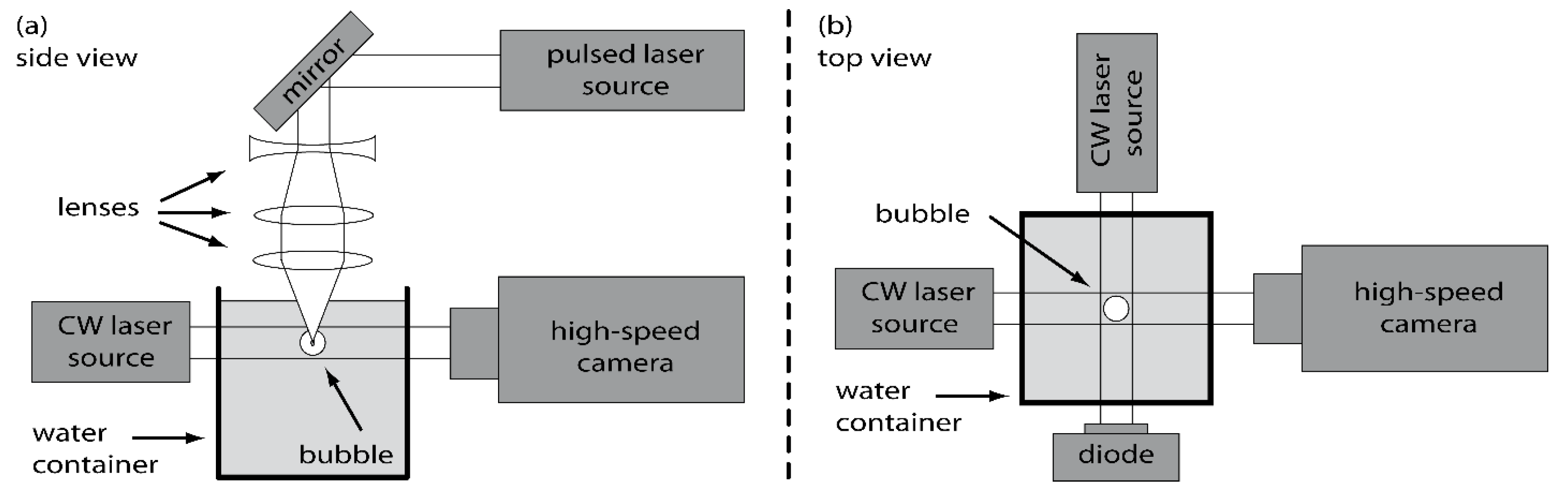
The cavitation bubble is generated by focusing a high-energy laser pulse into water (see
Figure 1a). The laser source is a Q-switched Nd:YAG laser (Saga, B.M. industries) generating pulses of 7 ns duration, and 10 mm diameter, at a wavelength of 1064 nm, and a maximum energy of 2300 mJ/pulse. The laser pulse is expanded by one diverging lens (focal length f = −50), and one converging lens (f = +100), before being focused by another converging lens (f = +20) into a cubic water container with sides measuring 50 mm.
The bubble is observed with a high-speed camera (Ultra Neo, NAC), capable of capturing 12 successive images at a maximum rate of 200 million frames per second, each photo having a resolution of 1082 × 974 pixels. The exposure time for each photo can be reduced to a minimum of 5 ns. A microscope zoom lens (VH-Z50L, Keyence, Osaka City, Japan) is mounted on the camera in order to magnify the image by up to 500 times. This lens has a long working distance of 85 mm among different magnifications which allows it to observe a small 1.22 × 0.90 mm area in a container. The lens mount adapters of Keyence-mount to C-mount and C-mount to F-mount were used for connecting between the camera and the lens. A continuous wave laser source of 1 W at maximum and 1.5 mm in diameter (SDL-532-1000TL, Shanghai Dream Lasers) is used to illuminate the bubble from the back (see
Figure 1). The short exposure time of 5 ns and the collimated beam provided by the continuous wave laser with an averaged light intensity of 0.56 W/mm
2 at 532 nm allow the shock waves to be visible on the high-speed video. The spatial resolution of the photo is 1.1 µm/pixel so that the shock wave thickness of 7.5 µm (7 pixels) can be clearly imaged. The videos presented in this paper are taken at 5 or 10 million frames per second, with a magnification of 300 times.
A second continuous wave laser and a photodiode are used to monitor the dynamics of the bubble through optical beam deflection. The laser beam passes through the location of the generation of the bubble, and ends on the photodiode, as shown in
Figure 1b. When the bubble is generated, its interface deflects the light of the laser, which reduces the light reaching the photodiode. The optical beam deflection technique has been previously used to investigate the dynamics of a cavitation bubble [
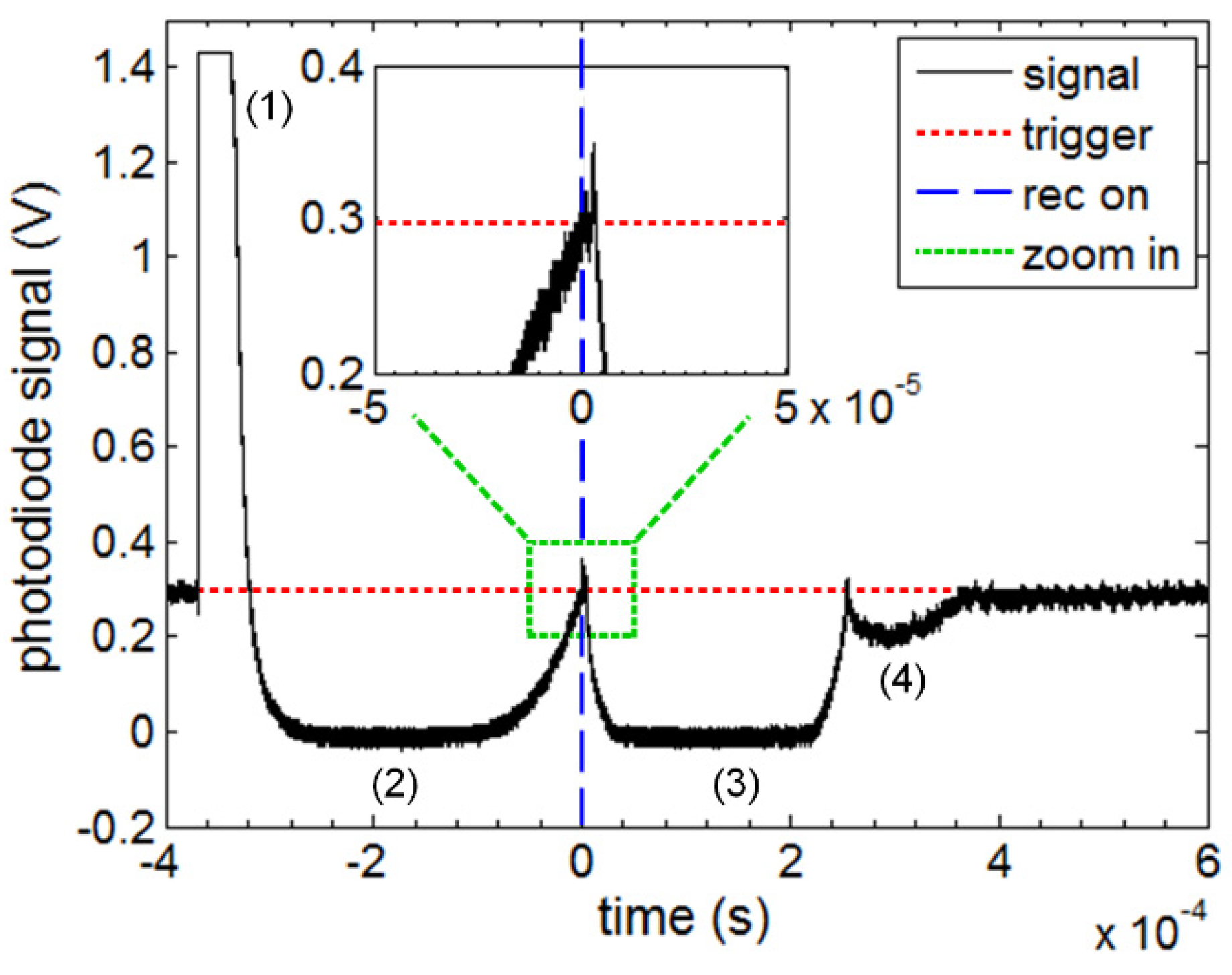
20]. A typical photodiode signal from our experiment is shown in
Figure 2. At the generation of the bubble, a large peak is visible on the signal. This is caused by the intense light emitted by the pulsed laser required for the generation of the bubble. The main bubble (2) and two successive rebounds, (3) and (4), are observed on the signal. The maximum radius of the bubbles can be estimated from the period of oscillation using the Rayleigh–Plesset equation [
21]. The maximum bubble radius as a function of the collapse time, which is equal to half of the bubble oscillation time, for a spherical collapse is given by
where
Rmax is the bubble maximum radius,
tcoll is the collapse time,
P∞ is the pressure in the liquid, and
ρ is the liquid density. In
Figure 2, the maximum radius of the bubble, the first rebound, and the second rebound are 2.0, 1.4, and 0.6 mm, respectively. The size of the bubble and its rebounds is large enough to cover the surface of the photodiode (1 × 1 mm
2).
The signal recorded by the photodiode drops to 0 when this happens, as is visible for (2) and (3) in
Figure 2. Note that the radius of the second rebound (4) is larger than the surface of the photodiode, although the signal does not decrease to 0. It is likely that the bubble moved out of the laser beam axis during the oscillations, allowing light to reach the photodiode.
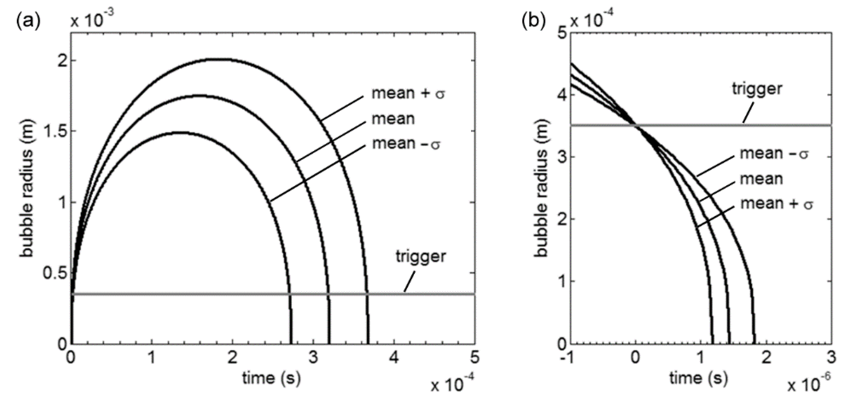
A reliable synchronization system is necessary in order to record the generation of shock waves at the very last stage of the collapse. The average lifetime of the bubbles generated with our setup is 320 µs, and the standard deviation σ is 47 µs. This standard deviation is large compared with the characteristic time scale of the shock formation (<<1 µs), and the duration of one video (from 0.1 to 1.1 µs). If the commencement of the high-speed video is synchronized to the bubble generation with a fixed delay equal to the average lifetime, the probability to observe the shock formation on the videos is less than 1.2%.
To improve the probability of visualizing the shock formation, the optical beam deflection technique can be used to trigger the start of the high-speed videos. The trigger signal to the camera was generated by measuring the photodiode signal with an oscilloscope (LeCroy, WaveSurfer 104MXs) and using the oscilloscope’s trigger function which works when a certain value was exceeded.
Figure 3 shows the radius as a function of time for three bubbles, corresponding to the average, the average + σ, and the average-σ. If the three curves are synchronized at the bubble generation, the time interval where the collapse can occur is 94 µs (within the standard deviation). However, if the curves are synchronized at a given radius of 20% or the average maximum bubble radius (0.35 mm), the time interval where the collapse can occur is 0.7 µs. The time interval is two orders of magnitude smaller, and the probability of observing the shock formation on the videos at 1 million frames per second is 100%. Note that, in practice, the noise on the photodiode signal reduces the accuracy of the synchronization. However, the improvement is still considerably significant.
3. Results
The high-speed images reveal that the bubbles generated with our methodology are not perfectly spherical. The refraction, induced by the change of medium—from air to water, and by the use of a lens—can cause multiple breakdown sites and the generation of a slightly elongated bubble. Although the bubble seems spherical during most of the growth and the collapse, the asymmetry is significant at the last stage of collapse. The asymmetry causes one side of the bubble to reach the center of the bubble first, giving the bubble a toroidal shape at the final stage of collapse. The liquid flowing through the center of the torus is called the microjet. The dynamics of the microjet are strongly dependent on the asymmetry; it may be caused by the shape of the bubble [
22], an existing pressure gradient [
7], or a boundary near the bubble [
23]. Note that when multiple breakdowns occur, two bubbles might coalesce, or grow and collapse attached to each other, which will affect the dynamics of the collapse of the bubbles.
The bubbles we observed are classified into three groups, depending on the features of the collapse: (a) quasi-spherical bubbles, (b) elongated bubbles, and (c) toroidal bubbles. The formation of the shock waves for each case is presented in the following sections.
3.1. Type-A: Quasi-Spherical Bubbles
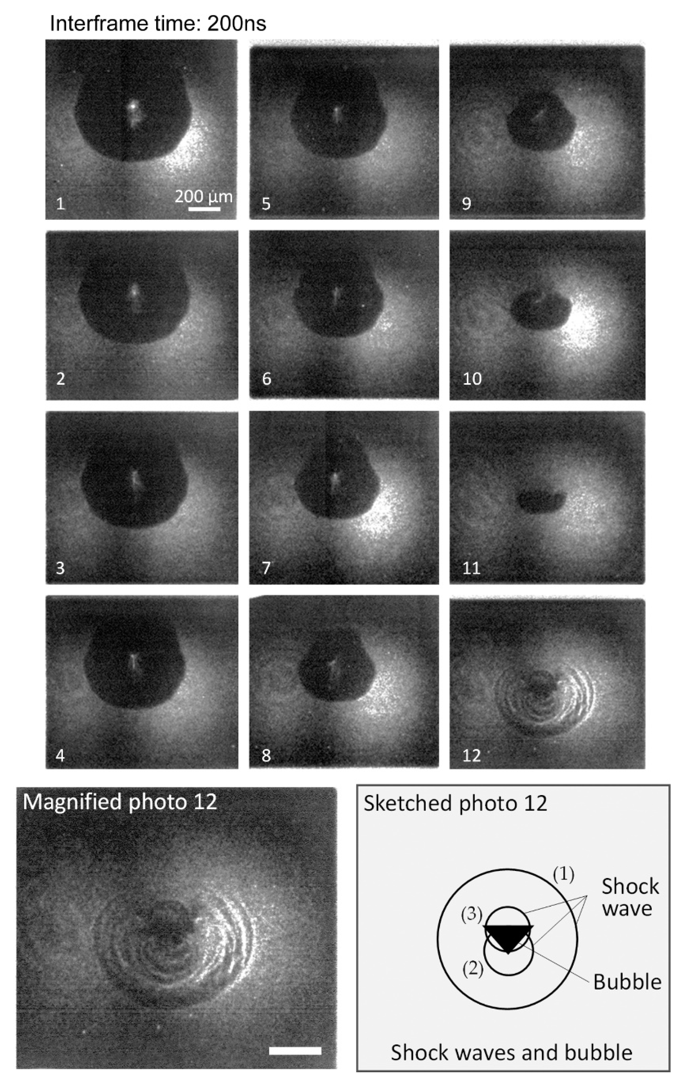
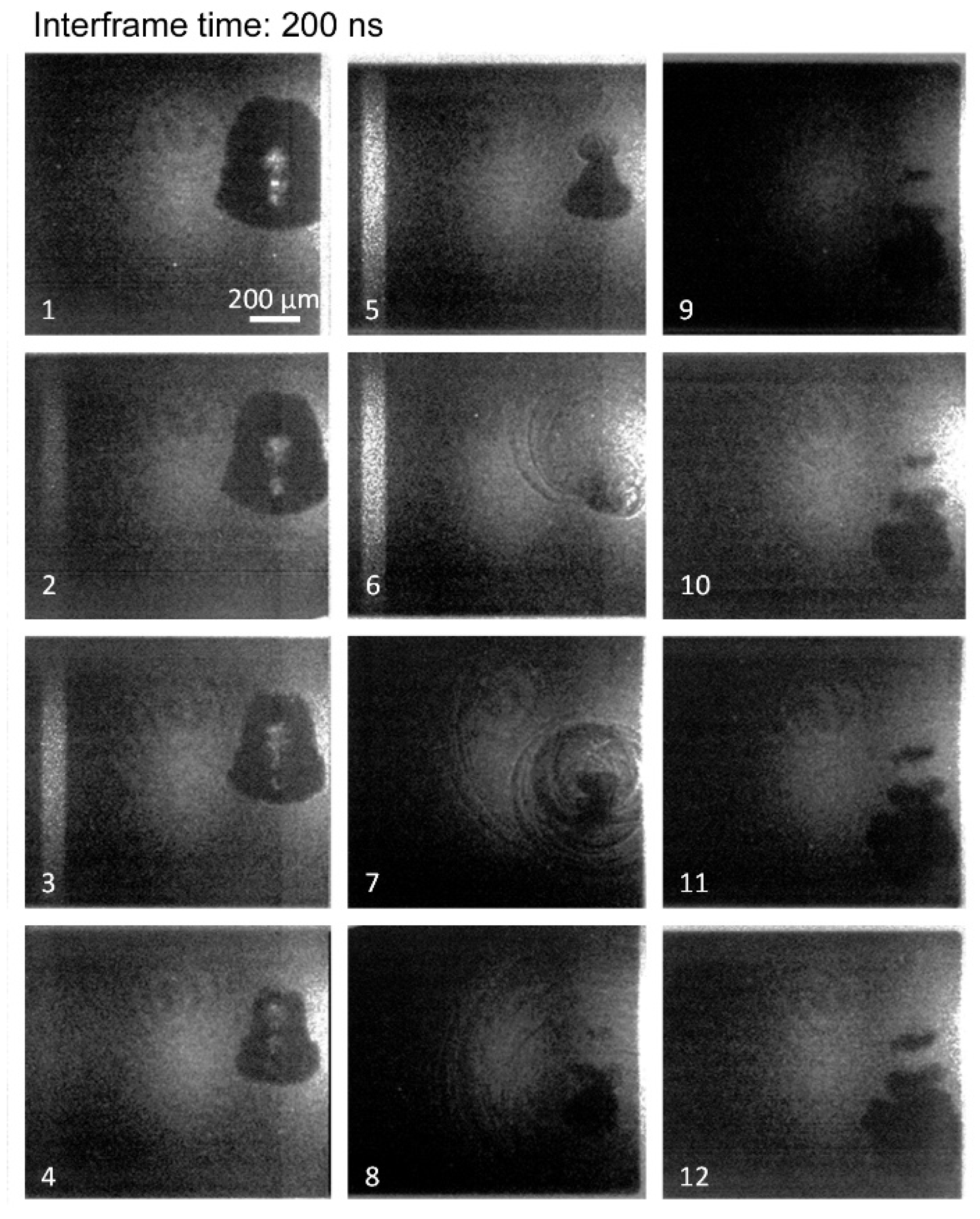
The collapse of a quasi-spherical bubble is presented on
Figure 4. The images are taken with a frame rate of 5 million frames per second and an exposure time of 5 ns. The collapse is not perfectly spherical. The bubble flattens during the last stage of the collapse, which suggests the formation of a microjet. In photo 11, the width of the bubble is twice its height. At the last stage of the collapse shown in the photo 12 and magnified photo 12, the bubble shrinks to a width of 200 µm and a height of 80 µm. It reveals that several shock waves are generated and three featured shock waves can be extracted as shown in the sketched photo 12 (bottom-right). One shock wave (1) is visible around the bubble, while two shock waves closer to the bubble, (2) and (3), are formed above and below the bubble.
This observation suggests that shock waves are formed at different locations on the bubble and at different instances of the final stage of the collapse.
The formation of these multiple shock waves may be explained as follows. When the microjet forming from the top of the bubble hits the diametrically opposed bubble interface, a water hammer shock wave is generated at the location of the impact, corresponding to (1) on the sketched photo 12 of
Figure 4 bottom-right. Meanwhile, the toroidal bubble still shrinks. When the toroidal bubble reaches its minimum volume, a compression shockwave is emitted, which is visible as (2) and (3). The distance between the shock (1) and (2) is 90 µm. Assuming that the shocks travel at the velocity of the sound (≈1500 m/s), the delay between the formation of these two shocks is 60 ns.
3.2. Type-B: Elongated Bubbles
Multiple breakdown sites can occur when the laser pulse is not focused on one small volume of the liquid. This phenomenon is more likely to occur at a higher laser intensities, as the volume where the energy density of the pulse exceeds the water breakdown limit is larger. The breakdown can occur before the focusing point. Multiple breakdowns can lead to the formation of two or more bubbles either coalescing or attached to each other during the whole growth and collapse process, resulting in one elongated bubble. The question of the coalescence of the generated bubbles is beyond the scope of this paper. However, the results presented here reveal interesting findings on that matter.
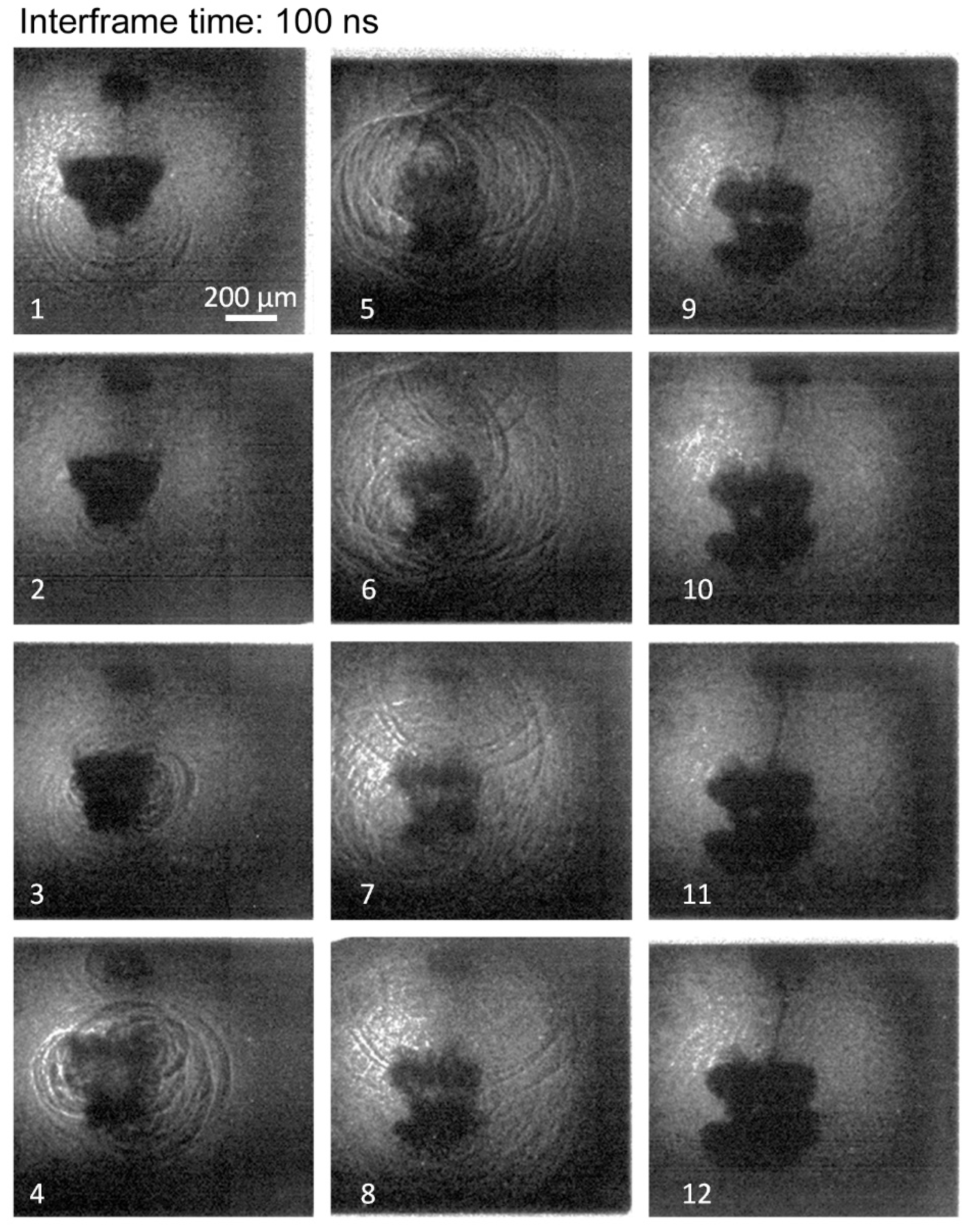
A typical example is shown in
Figure 5, recorded at 5 million frames per second. The bubble is vertically elongated during the collapse (photos 1 to 4). The collapse is not symmetric, as the upper half of the bubble collapses before the lower half. A first shock wave is emitted from the upper half of the bubble (photo 5), a second is emitted 200 ns later (photo 6), when the lower half of the bubble collapses. It is as if the upper and lower half of the bubble behaved independently, each collapsing at different instants. In this case, the water hammer shock wave is not clearly distinguished from the compression shock waves. Therefore, it can be assumed that, although a microjet may form, the water hammer shock is either absorbed by the lower half of the bubble, hidden by the lower half of the bubble, or the microjet does not hit the bubble interface with enough velocity to generate a visible shock. The collapse of the lower half of the bubble (photo 7) features several distinct shock waves (dark circles on the photo). The origin of each of the shock waves is difficult to determine in this configuration, because the influence of the rebounding upper half of the bubble is not clear. However, we can still observe one shock wave encircling several shock waves (photo 7), which is similar to what was observed for a quasi-spherical bubble.
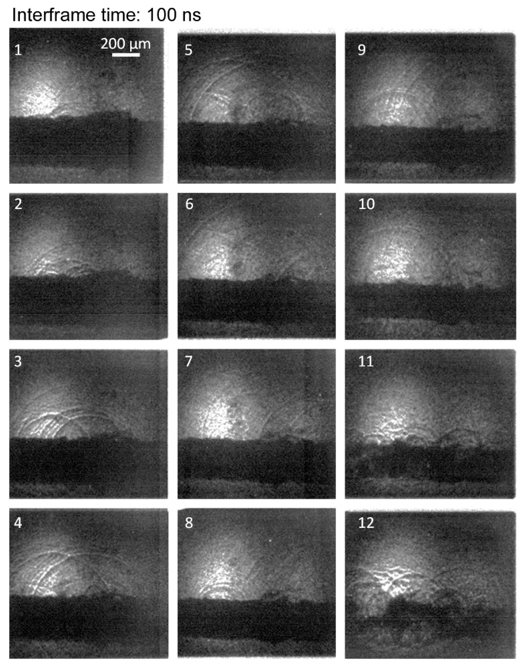
Figure 6 presents an example of an elongated bubble collapse recorded at 10 million frames per second. A shock wave, assumed to have formed at the bottom of the bubble, is visible in photo 1. A smaller bubble above the main bubble, probably formed because of the multiple laser breakdown sites, can also be noted. The main bubble shrinks, and shock waves are generated from the middle of the right side of the bubble in photo 3. In photo 4, shock waves are generated from several locations on the bubbles. The bubble is cut in two, an upper torus, and a lower torus. Both tori grow, while the shock waves travel away from the bubble, creating a complex pattern visible in photos 4 to 7. The small bubble above the main bubble collapses and releases shock waves in photo 4, adding to the shock wave pattern. The two main tori and the smaller bubble continue to grow larger and darker in the following photos, while the shock waves leave the field of view.
3.3. Type-C: Toroidal Bubble
On several of the high-speed videos, the bubble takes the shape of one wide torus at the point of collapse. The mechanisms leading to such a large torus are not clear because the videos only exhibit the last stage of the collapse. We assume that this occurs when the energy of the laser pulse is higher than usual, due to laser output energy fluctuations, leading to a larger asymmetric bubble. Nevertheless, the observations reveal valuable information about the formation of shock waves at the collapse.
The high-speed videos showed that multiple shock waves are formed during the collapse of these large toroidal bubbles. However, the cause of the formation of multiple shock waves differs from the two cases presented before, i.e., no water hammer shock waves have been observed.
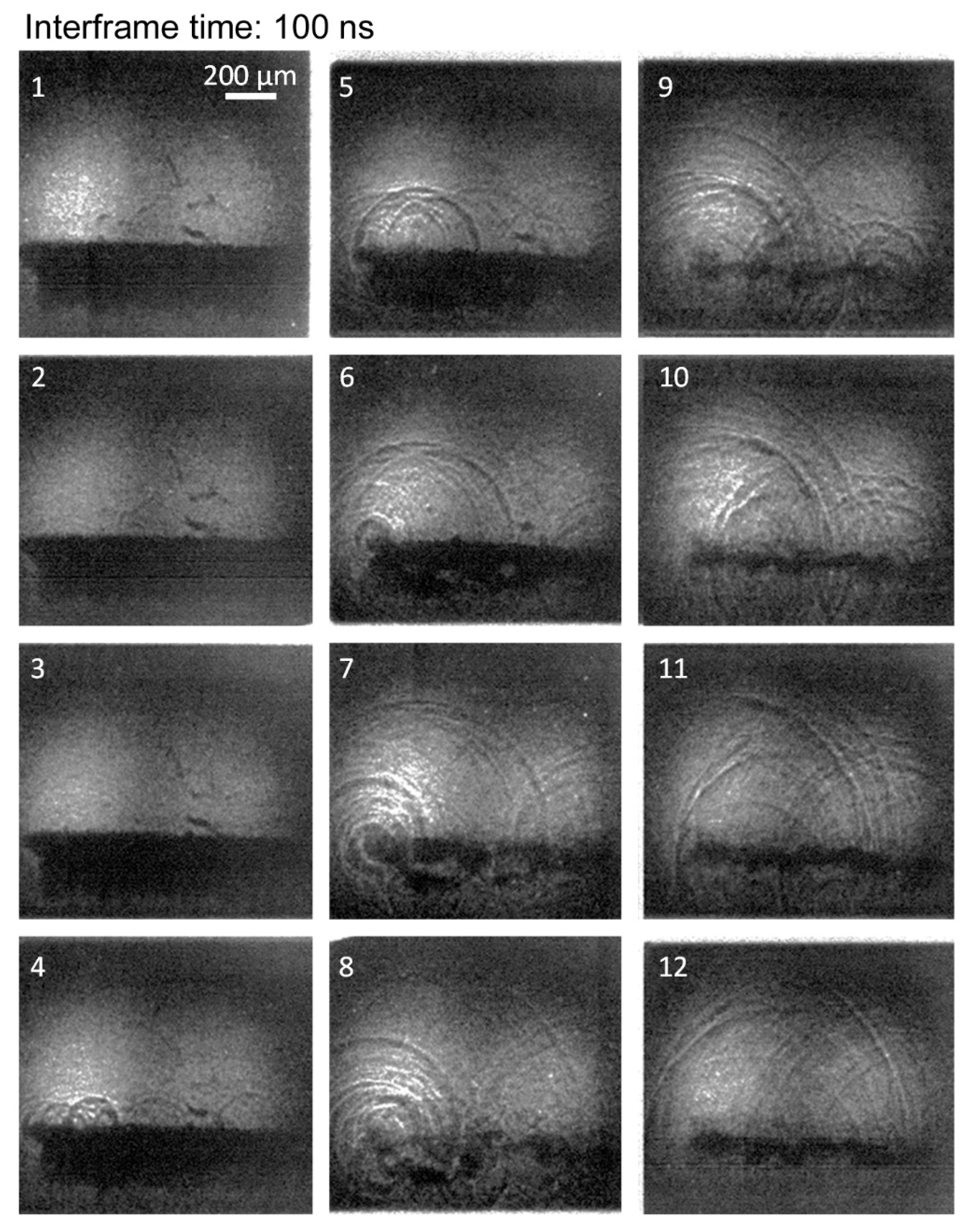
Figure 7 shows that several shock waves form at different times along the whole torus. The first shock waves are formed in photo 1. New shock waves are continuously forming until photo 12, a duration of 1.1 µs. Therefore, the number of shock waves and the interval of time during which the shocks are generated is larger than in the case of a quasi-spherical bubble.
Figure 8 reveals particularly interesting information about how the multiple shock waves are generated during the collapse process. The video also exhibits the formation of multiple shock waves at the collapse of a large toroidal bubble. Shock waves are generated at several locations along the torus between photo 4 and photo 9, i.e., over 500 ns. However, the bubble minimum volume is reached between photo 8 and photo 9. This indicates that all the shock waves form during the compression of the bubble, shortly before the minimum volume is reached. We also observe, in photos 8 and 9, that the toroidal bubble breaks into several distinct smaller bubbles at the very final stage of the collapse. We can thus assume that the multiple shock waves are formed because the torus collapses asynchronously—i.e., some parts before others—creating multiple shock fronts rather than two well defined fronts (water hammer and compression), as observed for quasi-spherical bubbles.
4. Discussion
The phenomena observed in the case of a quasi-spherical bubble are similar to those of the collapse of a bubble near, but not touching, a solid surface (i.e., for a standoff parameter
γ =
d/Rmax > 1, where
d is the distance between the bubble center and the wall, and
Rmax the bubble maximum radius). In our experiment, the bubble is deformed in one direction because of the initial shape of the plasma generating the bubble. In the case of the bubble close to a solid surface, the presence of the surface deforms the bubble in the normal direction. Both deformations lead to the formation of a microjet and multiple shock waves. The formation of a water hammer shock wave followed by the compression shock wave has already been observed experimentally [
4,
5] and confirmed numerically [
24,
25] in the case of bubbles near a solid surface. The use of a microscope lens in our setup improves the spatial resolution. We can observe that the shock fronts are not as sharp as expected. Several fronts seem to follow each other (successive dark and clear lines over small distances on the photos) originating from the same location. This particular multi-front structure suggests that the shock waves are not released as one sharp single front, but that several pressure peaks form from one small area of the bubble. These multiple fronts could be due to waves or instabilities at the bubble interface, where—even within a local area on the bubble interface—several shocks might be formed. Multiple fronts are not observed with numerical studies due to implementation of a smooth interface, leading to a local single shock front. They may not be observed experimentally if the spatial resolution is insufficiently large. The formation of the two distinct shockwaves has also been reported in the case of a bubble near a free surface, with shadow graphic images of the shockwaves, and the corresponding front light images revealing the dynamics of the microjet within the bubble [
26]. The multiple fronts are visible at the collapse of the toroidal part of the bubble.
The observation of elongated bubbles revealed a sequential collapse of the bubbles: one side of the bubble collapses and releases a shock wave before the other side of the bubble. The single bubble bounces back and splits into two rebound bubbles. The behavior of the elongated bubbles suggests that, at the last stage of the collapse, the gas inside the bubble does not behave as one homogeneous body. The supersonic velocities of the interface allow one part of the bubble to collapse independently of the rest of the bubble. The local collapses lead to the formation of separated rebound bubbles. An alternative hypothesis explaining the behavior of the elongated bubble suggests that these bubbles are formed by two or more bubbles attached to each other. The bubbles would not coalesce, and the thin interface between the bubbles would not be visible at the magnification used here. One bubble would collapse slightly before the other because the sizes, and consequently the lifetimes, of each bubble are different. At the collapse, the bubbles separate because of the large velocity difference at the interface.
The collapse of the toroidal bubbles observed here is reminiscent of the collapse of a laser-induced bubble on the surface of a solid boundary. In the case of a bubble collapsing on a solid surface, the bubble starts with a hemispherical shape. The bubble interface furthest from the surface moves towards the inside of the bubble, creating a torus with a large diameter, which then collapses on the solid surface. It has been observed that, in this case, the toroidal bubble also breaks into several smaller bubbles at the final stage of the collapse [
27]. The cause of the breaking of the bubble is the instability of the toroidal shape. The collapse of such bubbles on the solid surface is reported to be particularly erosive [
28]. It is assumed that the ‘splashing’ at the collapse of numerous small bubbles increases the interval of time during which a very high pressure is applied to the surface. The high-speed videos presented in this paper show that the formation of shock waves lasts at least twice as long as that of a quasi-spherical bubble collapse. We can observe formation of multiple shock waves by multiple small bubbles. Therefore, our results confirm the assumptions made for the explanation of ‘splashing’ erosion.


