Abstract
Real-time Simulation (RTS) is one of the effective means via which to study device level or system level dynamics, such as power converter online testing, evaluation, and control, and power system stability analysis. The RTS -enabled design-chain offers a time -effective, low-cost, and fail-safe development process. As the penetration of renewable energy is becoming higher, the demand in hybrid system real-time simulation becomes imperative, where fast-dynamic device level power converters and slow -dynamic large -scale power systems are simulated at the same time. This paper introduces a novel hybrid real-time simulation architecture based on the central processing unit (CPU) and the field-programmable gate array (FPGA). Compared with the off-the-shelf power system real-time simulation system, it offers both wide time scale simulation and high accuracy. The multi-time scale model can perform electromechanical electromagnetic transient hybrid simulation, which can be applied to the research of power systems penetrated with power converters. In the proposed simulation platform, the communication delay is introduced when different RTS platforms exchange real-time data. The communication delay should be considered in the stability analysis of the grid-connected inverters in a weak grid environment. Based on the virtual impedance characteristic formed by the control loop with and without communication delay, the impedance characteristics are analyzed and inter-simulator delay impacts are revealed in this paper. Theoretical analysis indicates that the communication delay, contrary to expectation, can improve the virtual impedance characteristics of the system. With the same hardware simulation parameters, the grid-converter system is verified on both the Typhoon system alone and the Typhoon-dSPACE-SpaceR hybrid simulation platform. The THD value of grid current in a weak grid environment that works in the Typhoon system is 4.98%, and 2.38% in the Typhoon-dSPACE-SpaceR hybrid simulation platform. This study eventually reveals the fact that the inter-simulation delay creates the illusion that the control system built in the novel hybrid real-time simulation is more stable under weak grid conditions.
1. Introduction
Nowadays, energy demand and environmental problems are becoming more and more compelling. This gives tremendous momentum in renewable energy technology development. With the increasing penetration of renewable energy, the power quality of renewable power generation has received extensive attention, which brings about higher requirements for accurate power regulation and faults diagnosis capabilities [1]. grid-tie inverters are the main equipment used to connect distributed generation systems with the conventional utility grid [2,3]. Therefore, in order to accurately control output power, it is necessary to improve the efficiency of renewable energy grid-connected devices and the quality of grid-connected currents.
Real-time simulation is an important tool used to study power electronics and power systems, which enables graphical modeling, efficient emulation, and friendly parameter tuning. Through RTS -based debugging and observation, researchers can quickly and intuitively obtain the electromagnetic transient behavior characteristics of power electronic equipment and power systems under steady-state and transients, which is helpful in expediting control algorithms and protection strategy verification [4,5,6]. Off-the-shelf real-time simulation of power systems is mostly based on high-performance computers or computer clusters, where the computing unit mostly consists of CPU clusters. With the expansion of microgrid and the penetration of power electronic equipment in the power system, the computation power of CPUs does not match the requirements of the high-frequency switching action in power electronic simulation [7,8]. Compared with a CPU, field-programmable gate array (FPGA) has strong computing power and low communication delay. It has been extensively used in power electronic real-time simulation and has attracted more and more attention [9,10,11].
Presently, commercial and research real-time simulator computation cores include the following implementations. The first category is CPU -based; The featured commercial simulators include RT-LAB [12] and HYPERSIM [13] developed by OPAL-RT company, ARENE [14] developed by EDF (Electricite De France), NETOMAC developed by Siemens, and ADPSS developed by China Electric Power Research Institute. The other category is FPGA based; The benchmark product developed by Typhoon Inc. and MIT belongs to this category and is widely used in switching converter real-time simulation.
It can be observed from Table 1 that real-time simulators with CPU as the only computing unit offers a flexible, nonlinear solving capability and easy coding. While the switching power converter is connected to the power grid, it will inject high -frequency voltage/current perturbation to the power system, and will bring a huge computational burden to the CPU -based platform. FPGA can fill the gap of real-time simulation in such scenarios. The CPU-FPGA hybrid real-time simulator combines the advantages of the two, and it also induces the communication delay into the model. Therefore, it is urgent to launch a hybrid real-time simulator based on CPU and FPGA in the market, and to evaluate the difference between the performance of the simulation model and the real plant.

Table 1.
Evaluation of different hardware architectures.
The research on hybrid simulation technology of power systems started more than 40 years ago. The first hybrid simulation technology was NETOMAC, developed in Germany by Siemens in the 1970s [15]. Parallel algorithms are of great significance for accurate real-time simulation of a large-scale power system. Therefore, network segmentation methods of various computer cluster parallel algorithms have been produced. In [16], cluster parallel technology is used to analyze the sensitivity of the transient process, and the Jacobian matrix obtained from the simultaneous iterative solution of differential equations by Newton method is used to reduce the simulation calculation time; Ref. [17] uses the time division method to assign different time points or time steps to different computers for calculation at the same time; Ref. [18] uses the conjugate gradient iterative method to solve the linear equation in parallel, and the operation effect is good; Ref. [19] uses the Newton GMRES method to carry out parallel computing on heterogeneous computers with strong expansibility, and uses adaptive variable order prediction and multi-step coordination method to improve the efficiency of parallel computing. The research team, led by Snider and Kevin from Hong Kong Polytechnic University, researched hybrid simulation technology and realized the docking of SVC electromagnetic transient simulation program with conventional electromechanical transient simulation programs in [20]. Ref. [21] proposes a parallel interface data interaction protocol. In [22,23,24], the problems of parallel computing and real-time in a hybrid simulation are analyzed. Ref. [25] focuses on the hardware-in-the-loop (HIL) real-time simulation system of variable speed hydro-electric plants (VS-HEP), and a hydraulic modeling method using mathematical optimization programs to analyze and obtain the hydraulic static model is introduced. Ref. [26] introduces the latest developments of RTDS Technologies Inc., including the growth of high-performance processing space and the research of high-end processors in embedded design. For large-scale power system simulation, Ref. [27] introduces a hybrid real-time simulation tool combining real-time simulators and transient stability programs. The simulation results are similar to those of a large-scale real-time simulator, which verifies its feasibility. Ref. [28] introduces the latest improvement of an open-source real-time simulator DPsim, which can combine the characteristics of traditional vector and electromagnetic transient simulations.
Inspired by the above idea, a hybrid real-time simulator architecture is proposed in this paper, which combines the CPU-based and FPGA-based simulators. In the simulation system, the communication delay is introduced when different RTS platforms exchange real-time data. The communication delay cannot be ignored on the simulator during the stability analysis of the grid-connected inverters in a weak grid environment. The authors have investigated a grid-connected inverter control that uses grid voltage feedforward and PLL control method in this simulation platform, and verified the negative effects of the communication delay on the stability of the system [29].
In this paper, the impedance characteristics of a grid-tie inverter will be investigated in a proposed hybrid real-time simulation platform. Both theoretical and experimental investigations will be carried out to evaluate the impact of the inter-simulator delay to the control design of the inverter. Potential design pitfalls when using a hybrid simulation platform will also be revealed.
2. The Real-Time Simulation Configuration
The study of power electronics penetrated power systems demands mixed small time step switching systems and large complex electric networks simulations, thus it is often necessary to use multi-core CPU or FPGA hardware with strong computing power for calculations. The simulation scale and computing power of the real-time simulation system depend on the amount of hardware resources of the simulator. In this section, a mixed simulation platform is proposed.
2.1. Platform Framework
The CPU-based RTS system SPACER, a real-time simulation system with enhanced computation power, is shown in Figure 1. The platform can directly load the mathematical model of the dynamic system established in MATLAB/SIMULINK for simulation, control, and testing. Each RTS has up to 12 CPU cores, realizing multi-task parallel processing. Meanwhile, the target machine has an integrated PCI-E expansion Bus for expanding multiple I/O expansion boxes.
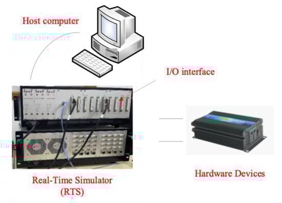
Figure 1.
SPACER real time simulator.
Another RTS system is based on FPGA with a dedicated model library; this system is called Typhoon (a Hardware-In-Loop system for power electronics), as shown in Figure 2. It offers a complete set of solutions for engineering projects, such as power electronics system design, verification, real-time simulation, and testing.
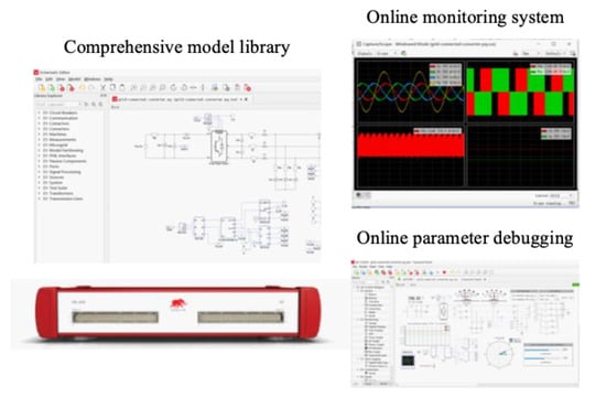
Figure 2.
Typhoon HIL402.
Table 2 shows the specifications of SPACER and Typhoon. As demonstrated, the SPACER only uses the CPU as the computing unit, and, thus, large time scale power grid models can be built into this simulator. Power electronics simulation models are built in the Typhoon HIL. The dSPACE RTS is a real-time development and testing platform of control systems, which is seamlessly connected with MATLAB/Simulink. The architecture of the proposed simulator is shown in Figure 3.
Table 2.
Performance Parameters of Real-Time Simulator.
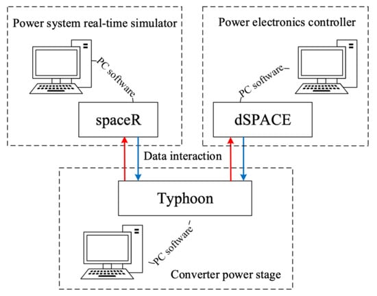
Figure 3.
Platform framework.
2.2. Data Interaction between the Platform
In the proposed simulator, there are two data interaction modes: the ethernet data communication and the I/O port communication, as shown in Table 2.
- (1)
- Ethernet data communication
Ethernet is a baseband LAN technology. Its maximum data transmission rate is 1GBIT/s, which cannot support sustainable network data transmission. Its communication protocols include TCP and UDP, and their characteristics are shown in Table 3.
Table 3.
Specification comparison between TCP and UDP.
In this study, the TCP protocol is adopted when testing the data communication function. The single simulator data transmission test results are shown in Figure 4, where the data are transmitted without omission. The results show that the data cannot be well transmitted between two simulators (SPACER and Typhoon HIL). The primary reason for this can be that the simulators are produced by different manufacturers with protocols that differ from the TCP protocol, thus, the performance and reliability of the real-time simulator is significantly reduced.
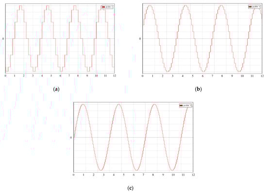
Figure 4.
Data acceptance waveforms at different time intervals. (a) Time interval is 250 ms; (b) Time interval is 10 ms; (c) Time interval is 2 ms.
- (2)
- I/O port data communication
Analog port communication is much simpler. As shown in Table 2, both Typhoon HIL and SPACER have 16 analog output ports and 16 analog input ports, and have the same analog signal transmission range of −10~10 V. Since the signal resolution is 16 bits, the theoretical error can be calculated. As can be seen in the experimental verification result shown in Figure 5, the actual signal error is about 0.1%, no data are missing, the waveform is not distorted, and it can meet the engineering requirements. However, the analog port communication will bring about a new type of communication delay at the microsecond level.
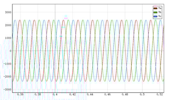
Figure 5.
Data waveform obtained by analog port communication.
After the above comparison of the data error caused by two different data interaction modes, analog port communication is applied in this paper for experiments, and a series of theoretical research and experiments are carried out to verify the impact of communication delay.
3. Influence of Communication Delay in Weak Grid
3.1. Modeling of Grid-Connected Inverters
This proposal focused on the analysis of a three-phase LCL-typed grid-connected inverter, as shown in Figure 6. the control system of a grid-connected inverter usually adopts grid voltage feedforward [30,31,32] to enhance the dynamic response performance of the grid-connected inverter under the situation of grid voltage disturbance, and to suppress the grid current harmonics caused by grid voltage harmonics. The phase-locked loop (PLL) is applied to obtain the real-time grid voltage phase. Here, the LCL filter includes the converter side filter inductance L1, filter capacitor C, and the grid side filter inductance L2. Udc is the DC-link voltage. Upcc is the PCC voltage, which is the synchronous reference voltage of the PLL. Based on this structure, a weak grid can be denoted by the Thevenin equivalent circuit, where an ideal voltage source Ug is connected in series with the grid impedance Lg. Grid current Ig is under close-loop control, and the current reference is directly given by idqref. The capacitor-current-feedback for active damping is applied to suppress the LCL filter resonance peak, where Kc is the feedback coefficient of capacitive current.
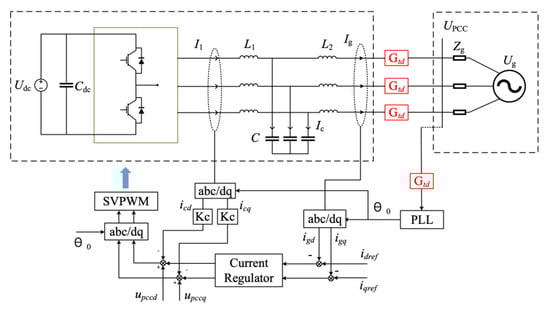
Figure 6.
The topology structure of the LCL grid-connected inverter.
Figure 7 shows a typical control structure of grid current feedback. Upcc can be replaced by . According to the mason transformation rule, Figure 7a can be transformed into Figure 7b through a series of equivalent transformations and simplifications. The detailed transformation process is presented in Appendix A. The open-loop transfer function of the system can be calculated as Equation (1):
where, Gc(s) is the inductor current controller, also known as the proportional-integral (PI) controller, which can be expressed as:
where Kp and Ki is proportional gain and the integral gain respectively.
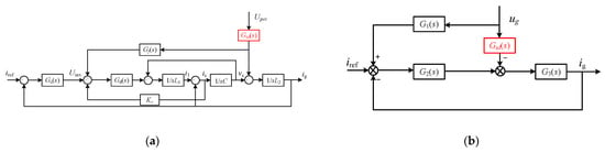
Figure 7.
Block diagram of the LCL-typed grid-connected inverter. (a) Control block; (b) Simplified control block.
Gd(s) is the controller delay, and Gtd(s) is the communication delay caused by real-time data interaction between the simulators. They can be expressed as [10]:
Overall, 1.5Ts is total delay time caused by sampling and calculation process of PWM while Ttd is data interaction time on the platform.
3.2. Virtual Impedance Characteristic of Control Loop with Communication Delay
3.2.1. Virtual Impedance Characteristic of Capacitive Current Feedback Control
As shown in Figure A1b of Appendix A, capacitive current feedback control forms a virtual equivalent impedance Zeqc in parallel with the filter capacitive C. It can be formulated as:
where Reqc0 is the virtual equivalent resistance of capacitive current feedback without digital control delay, as
When there is a digital control delay, the Zeqc can be expressed as the virtual equivalent resistance Reqc and reactance Xeqc in parallel.
3.2.2. Virtual Impedance Characteristic of Grid Voltage Feedforward Control
The actual voltage feedforward is the Upcc, which contains the ideal grid voltage ug and capacitance voltage uc, and can be calculated as follows,
Notably, as shown in Figure 6, the novel simulator platform proposed in this paper causes a communication delay Gtd. Thus, it can be found that the capacitor voltage part of the feedforward quantity in Figure 8a is equivalent to forming an equivalent virtual impedance Zeqv in parallel with the output filter capacitor as follows,
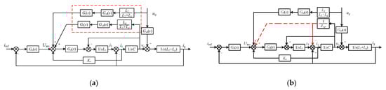
Figure 8.
Equivalent virtual impedance of grid voltage feedforward control scheme. (a) Before simplification; (b) After simplification.
In which, Xeqv0 is the equivalent virtual reactance formed by grid voltage feedforward control when there is no digital control delay and the communication delay, and its calculation result can be expressed as,
When there is a delay of digital control and transmission line, Zeqv can be expressed as a virtual equivalent resistance Reqv and a virtual equivalent reactance Xeqv in parallel, and can be respectively calculated as follows,
It can be seen from the above expression that Zeqv is affected by the grid inductance Lg. Under the condition of a strong power grid, Zeqv tends to be infinity, thus, the impact on system stability caused by Zeqv can be ignored. However, under the condition of a weak current grid, Zeqv is a finite value, and the impact cannot be ignored. Therefore, this research method is only suitable for weak power grid conditions.
3.2.3. Virtual Impedance Characteristic of Control Loop
Based on the analysis above, the virtual impedance characteristics of capacitive current feedback and grid voltage feedforward are all affected by the digital control delay, however only the virtual impedance characteristics of grid voltage feedforward are affected by the communication delay. For further analysis, the effects of digital control delay and communication delay on the virtual impedance characteristics will be studied separately.
Assuming that the communication delay can be ignored, the virtual impedances of grid voltage feedforward and capacitive current feedback are:
Therefore, the equivalent virtual impedance Zeq0 without digital control delay can be expressed as:
From Equation (16), the equivalent virtual impedance is determined not only by resistance Reqc0, but also by reactance Xeqv0. The Xeqv0 is capacitive reactance, which has a low-frequency offset effect on the system resonant frequency and is related to grid impedance Lg and coefficient of grid voltage feedforward Gf.
Then, the equivalent virtual impedance Zeq with digital control delay can be expressed as an equivalent resistance Req and an equivalent reactance Xeq in parallel, calculated as follows,
By taking the communication delay in consideration, the virtual impedances of grid voltage feedforward and capacitive current feedback are:
Thus, the equivalent virtual impedance Zeq can be expressed as an equivalent resistance Req in parallel with an equivalent reactance Xeq as,
The frequency response of Zeq and Zeqtd is shown in Figure 9, where fs is the sampling frequency. The frequency characteristics of equivalent resistance and reactance are affected by grid impedance Lg, grid voltage feedforward coefficient Gf, capacitor current feedback coefficient Kc, digital control delay 1.5Ts and communication delay Ttd.
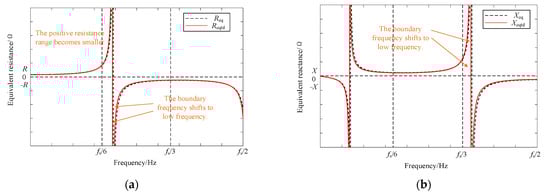
Figure 9.
Frequency characteristics of virtual equivalent impedance. (a) Frequency characteristics of equivalent resistance Req and Reqtd; (b) Frequency characteristics of equivalent reactance Xeq and Xeqtd.
The communication delay on the frequency characteristics of equivalent resistance and reactance will be illustrated as follows. It can be seen from the frequency response results (Figure 9) that after introducing communication delay, the boundary frequency and amplitude of equivalent resistance and reactance change. The boundary frequency of Xeqtd is shifted to low frequency by 25 Hz; The positive resistance range of Reqtd becomes smaller, which can render the system unstable.
It can be concluded that the communication delay has an impact on the system stability whilst the impact caused by the grid impedance is strong. Meanwhile, it can be seen from Figure 10 that the weaker the power grid, the larger the damping range of the equivalent virtual resistance of the control loop, and the resonant damping effect of the control loop can be effectively improved.
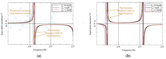
Figure 10.
Frequency characteristics of virtual equivalent impedance under different grid impedance. (a) Frequency characteristics of equivalent resistance Reqtd; (b) Frequency characteristics of equivalent reactance Xeqtd.
4. Simulation and Experimental Verification
To verify the feasibility of the virtual impedance characteristic analysis above, the simulation models, as shown in Figure 4, are built into the proposed hybrid real-time simulation system. Meanwhile, the switching frequency of the inverter is 10 kHz. A filter with a cut-off frequency of 500 Hz is selected. Based on the design equation as in (25), the filter inductance and capacitance are selected to be 8 mH and 10 uF, respectively.
The main parameters are shown in Table 4.
Table 4.
Specifications of the Grid-tie Inverters.
The simulation results of communication delay are shown in Figure 11. The model established in Typhoon HIL obtains the power grid current waveform under both strong grid and weak grid conditions. As can be observed in Figure 11, when the grid impedance becomes larger, the grid current waveform worsens.
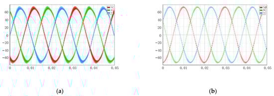
Figure 11.
Waveforms of grid current iga under different grid impedance. (a) Lg = 1 mH; (b) Lg = 0 mH.
To compare the quality of the grid-connected current, Figure 12 shows the harmonic distortion rate of the grid-connected current. The fast Fourier transform (FFT) value with Lg = 1 mH is 4.98% and with Lg = 0 mH is 3.27%; here, the former is obviously larger than the latter.
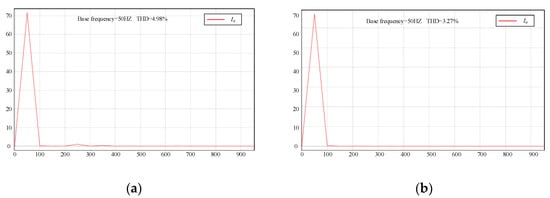
Figure 12.
FFT analysis of grid current iga under different grid impedance. (a) Lg = 1 mH; (b) Lg = 0 mH.
In order to compare these results with the simulation results in Typhoon HIL, where only control delay Td persists, the model is re-implemented in the proposed hybrid real-time simulator. The platform is shown in Figure 13. The power grid model is built by SPACER, while Typhoon HIL provides the inverter model. the simulation results of the inductor current waveform with and without grid impedance are shown in Figure 14a and Figure 14b, respectively. The FFT value with Lg = 1 mH is 2.36%, and with Lg = 0 mH is 6.94%, as shown in Figure 15a and Figure 15b, respectively. Here, the former is obviously smaller than the latter. The result is completely opposite to the previous results obtained on a single simulator, as shown in Figure 12.
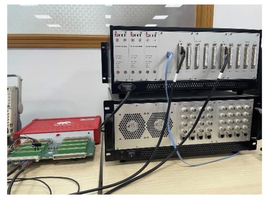
Figure 13.
Experimental platform.
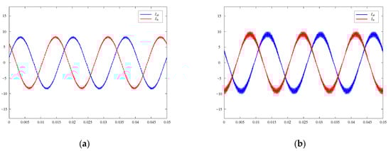
Figure 14.
Waveforms of grid current ig on the novel hybrid real-time simulator. (a) Lg = 1 mH; (b) Lg = 0 mH.
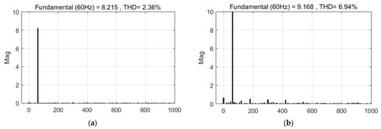
Figure 15.
FFT analysis of grid current ig on the novel hybrid real-time simulator. (a) Lg = 1 mH; (b) Lg = 0 mH.
Therefore, the above theory can be successfully verified by comparing the simulation results on different platforms. The influence of communication delay between platforms cannot be ignored, and the model of the hybrid real-time simulator under a weak grid can improve the power grid current waveform. the weaker the power grid, the smaller the current waveform harmonic, and the greater the quality of the waveform.
5. Conclusions
A hybrid real-time simulation platform is proposed in this paper, combining the computation engines of CPU and FPGA, which solves the challenges of co-existing simulation time scale and simulation accuracy. The communication delay of the hybrid real-time simulator impacts the system design. Through theoretical analysis and experimental verification, it is revealed that, in the real-time simulation environment, the communication delay will, surprisingly, improve the stability of grid-connected inverters connected to a weak grid. Therefore, designers who works with hybrid simulators without a synchronized system timing/clock can pay attention to this illusive phenomenon and take corresponding measures to ensure seamless design transition from RTS to physical plants.
Author Contributions
Conceptualization, H.G. and W.J.; methodology, S.P.; software, S.P.; validation, S.P. and M.L.; formal analysis, S.P.; investigation, S.P. and M.L.; resources, H.G. and W.J.; data curation, S.P.; writing—original draft preparation, S.P.; writing—review and editing, M.L. and J.W.; visualization, S.P.; supervision, H.G. and W.J.; project administration, H.G. and W.J.; funding acquisition, H.G. and W.J. All authors have read and agreed to the published version of the manuscript.
Funding
This research was funded by Yangzhou city-Yangzhou University Joint Fund grant number YZ2020169.
Institutional Review Board Statement
Not applicable.
Informed Consent Statement
Not applicable.
Data Availability Statement
Not applicable.
Conflicts of Interest
The authors declare no conflict of interest.
Appendix A
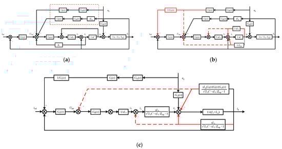
Figure A1.
Detailed simplified process of mathematical model. (a) Simplify process I; (b) Simplify process II; (c) Simplify process III.
References
- Zhang, Y.; Zhou, Q.; Zhao, L.; Ma, Y.; Lv, Q.; Gao, P. Dynamic Reactive Power Configuration of High Penetration Renewable Energy Grid Based on Transient Stability Probability Assessment. In Proceedings of the 2020 IEEE 4th Conference on Energy Internet and Energy System Integration (EI2), Wuhan, China, 30 October–1 November 2020; pp. 3801–3805. [Google Scholar]
- He, J.; Liu, P.; Duan, S. Stability Analysis of Multi-paralleled Grid-connected Inverters with Different Controllers in Weak Grid Condition. In Proceedings of the IECON 2020 The 46th Annual Conference of the IEEE Industrial Electronics Society, Singapore, 18–21 October 2020; pp. 2350–2355. [Google Scholar]
- Okada, N.; Fukushima, K.; Sano, K. A Method to Consider Voltage Distortion Caused by Interaction Grid-Connected Inverter and Distribution System. In Proceedings of the 2020 23rd International Conference on Electrical Machines and Systems (ICEMS), Hamamatsu, Japan, 24–27 November 2020; pp. 630–635. [Google Scholar]
- D’Agostino, F.; Kaza, D.; Martelli, M.; Schiapparelli, G.-P.; Silvestro, F.; Soldano, C. Development of a Multiphysics Real-Time Simulator for Model-Based Design of a DC Shipboard Microgrid. Energies 2020, 13, 3580. [Google Scholar] [CrossRef]
- Summers, A.; Johnson, J.; Darbali-Zamora, R.; Hansen, C.; Anandan, J.; Showalter, C. A Comparison of DER Voltage Regulation Technologies Using Real-Time Simulations. Energies 2020, 13, 3562. [Google Scholar] [CrossRef]
- Sodin, D.; Ilievska, R.; Čampa, A.; Smolnikar, M.; Rudez, U. Proving a Concept of Flexible Under-Frequency Load Shedding with Hardware-in-the-Loop Testing. Energies 2020, 13, 3607. [Google Scholar] [CrossRef]
- Saad, H.; Ould-Bachir, T.; Mahseredjian, J.; Dufour, C.; Dennetière, S.; Nguefeu, S. Real-Time Simulation of MMCs Using CPU and FPGA. IEEE Trans. Power Electron. 2015, 30, 259–267. [Google Scholar] [CrossRef]
- Matar, M.; Iravani, R. FPGA Implementation of the Power Electronic Converter Model for Real-Time Simulation of Electromagnetic Transients. IEEE Trans. Power Deliv. 2010, 25, 852–860. [Google Scholar] [CrossRef]
- Vijay, A.S.; Doolla, S.; Chandorkar, M.C. Real-time testing approaches for microgrids. J. Emerg. Sel. Top. Power Electron. 2017, 5, 1356–1376. [Google Scholar] [CrossRef]
- Faruque, M.D.O.; Strasser, T.; Lauss, G.; Jalili-Marandi, V.; Forsyth, P.; Dufour, C.; Dinavahi, V.; Monti, A.; Kotsampopoulos, P.; Martinez, J.A.; et al. Real-time simulation technologies for power systems design, testing, and analysis. IEEE Power Energy Technol. Syst. J. 2015, 2, 63–73. [Google Scholar] [CrossRef]
- Guillaud, X.; Faruque, M.O.; Teninge, A.; Hariri, A.H.; Vanfretti, L.; Paolone, M.; Dinavahi, V.; Mitra, P.; Lauss, G.; Dufour, C.; et al. Applications of real-time simulation technologies in power and energy systems. IEEE Power Energy Technol. Syst. J. 2015, 2, 103–115. [Google Scholar] [CrossRef] [Green Version]
- McLaren, P.G.; Kuffel, R.; Wierckx, R.; Giesbrecht, J.; Arendt, L. A real time digital simulator for testing relays. IEEE Trans. Power Deliv. 1992, 7, 207–213. [Google Scholar] [CrossRef]
- Kumar, A.; Bahjaoui, A.; Musunuri, S.K.; Rout, B. Design and Tuning of Multi-Band Based Power System Stabilizer and Implementation in HYPERSIM. In Proceedings of the 2019 20th International Conference on Intelligent System Application to Power Systems (ISAP), New Delhi, India, 11 April 2019; pp. 1–6. [Google Scholar]
- Devaux, O.; Levacher, L.; Huet, O. An advanced and powerful real-time digital transient network analyzer. IEEE Trans. Power Deliv. 1998, 13, 421–426. [Google Scholar] [CrossRef]
- Bélanger, J.; Snider, L.A.; Paquin, J. A Modern and Open Real-Time Digital Simulator of Contemporary Power Systems. In Proceedings of the International Conference on Power Systems Transients (IPST 2009), Kyoto, Japan, 10 October 2009. [Google Scholar]
- Kulicke, B. NETOMAC Digital program for simulating electromechanical and electromagnetic transient phenomena in AC systems. Elektrizitätswirtschaft Heft. 1979, 78, 18–23. [Google Scholar]
- Wang, X.; Bao, C.; Ruan, X.; Li, W.; Pan, D. Design considerations of digitally controlled LCL-filtered inverter with capacitor current feedback active damping. IEEE J. Emerg. Sel. Top. Power Electron. 2014, 2, 972–984. [Google Scholar] [CrossRef]
- Hou, G.; Vittal, V. Cluster Computing-Based Trajectory Sensitivity Analysis Application to the WECC System. IEEE Trans. Power Syst. 2012, 27, 502–509. [Google Scholar] [CrossRef]
- Li, Z.; Donde, V.D.; Tournier, J.; Yang, F. On limitations of traditional multi-core and potential of many-core processing architectures for sparse linear solvers used in large-scale power system applications. In Proceedings of the 2011 IEEE Power and Energy Society General Meeting, Detroit, MI, USA, 24–28 July 2011; pp. 1–8. [Google Scholar]
- Chen, Y.; Shen, C.; Wang, J. Distributed Transient Stability Simulation of Power Systems Based on a Jacobian-Free Newton-GMRES Method. IEEE Trans. Power Syst. 2009, 24, 146–156. [Google Scholar] [CrossRef]
- Su, H.; Chan, K.K.W.; Snider, L.A. Interfacing an electromagnetic SVC model into the transient stability simulation. In Proceedings of the International Conference on Power System Technology, Kunming, China, 13–17 October 2002; Volume 3, pp. 1568–1572. [Google Scholar]
- Su, H.; Chan, K.W.; Snider, L.A.; Chung, T.S. A parallel implementation of electromagnetic electromechanical hybrid simulation protocol. In Proceedings of the 2004 IEEE International Conference on Electric Utility Deregulation, Restructuring and Power Technologies, Hong Kong, China, 5–8 April 2004; Volume 1, pp. 151–155. [Google Scholar]
- Chan, K.K.W.; Snider, L.A. Development of a hybrid real-time fully digital simulator for the study and control of large power systems. In Proceedings of the 2000 International Conference on Advances in Power System Control, Operation and Management, APSCOM-00, Hong Kong, China, 30 October–1 November 2000; Volume 2, pp. 527–531. [Google Scholar]
- Guo, B.; Mohamed, A.; Bacha, S.; Alamir, M.; Boudinet, C.; Pouget, J. Reduced-Scale Models of Variable Speed Hydro-Electric Plants for Power Hardware-in-the-Loop Real-Time Simulations. Energies 2020, 13, 5764. [Google Scholar] [CrossRef]
- Sidwall, K.; Forsyth, P. Advancements in Real-Time Simulation for the Validation of Grid Modernization Technologies. Energies 2020, 13, 4036. [Google Scholar] [CrossRef]
- Song, J.; Hur, K.; Lee, J.; Lee, H.; Lee, J.; Jung, S.; Shin, J.; Kim, H. Hardware-in-the-Loop Simulation Using Real-Time Hybrid-Simulator for Dynamic Performance Test of Power Electronics Equipment in Large Power System. Energies 2020, 13, 3955. [Google Scholar] [CrossRef]
- Mirz, M.; Dinkelbach, J.; Monti, A. DPsim—Advancements in Power Electronics Modelling Using Shifted Frequency Analysis and in Real-Time Simulation Capability by Parallelization. Energies 2020, 13, 3879. [Google Scholar] [CrossRef]
- Wong, S.M.; Sze, K.M.; Snider, L.A.; Chan, K.W.; Larose, C. Overcoming the difficulties associated with interfacing different simulation programs. In Proceedings of the 2003 Sixth International Conference on Advances in Power System Control, Operation and Management ASDCOM 2003, Hong Kong, China, 11–14 November 2003; pp. 403–408. [Google Scholar]
- Pan, S.; Jiang, W.; Geng, H.; Wang, J.; Li, M. Evaluation of the Delay Effect in a Novel Hybrid Real-Time Simulation Platform. In Proceedings of the 2021 IEEE 1st International Power Electronics and Application Symposium (PEAS), Shanghai, China, 13–15 November 2021; pp. 1–6. [Google Scholar]
- Chan, K.K.W.; Snider, L.A. Electromagnetic electromechanical hybrid real-time digital simulator for the study and control of large power systems, PowerCon 2000. In Proceedings of the 2000 International Conference on Power System Technology, Perth, WA, Australia, 4–7 December 2000; Volume 2, pp. 783–788. [Google Scholar]
- Xu, J.; Qian, Q.; Xie, S.; Zhang, B. Grid-voltage feedforward based control for grid-connected LCL-filtered inverter with high robustness and low grid current distortion in weak grid. In Proceedings of the 2016 IEEE Applied Power Electronics Conference and Exposition (APEC), Long Beach, CA, USA, 20–24 March 2016; pp. 1919–1925. [Google Scholar]
- Hu, Y.; Xu, J.; Qian, H.; Bian, S.; Xie, S. Robustness and Harmonics Suppression of Grid-Connected Inverters with Different Grid Voltage Feedforward Compensations in Weak Grid. In Proceedings of the 2020 IEEE 29th International Symposium on Industrial Electronics (ISIE), Delft, The Netherlands, 17–19 June 2020; pp. 779–784. [Google Scholar]
Publisher’s Note: MDPI stays neutral with regard to jurisdictional claims in published maps and institutional affiliations. |
© 2022 by the authors. Licensee MDPI, Basel, Switzerland. This article is an open access article distributed under the terms and conditions of the Creative Commons Attribution (CC BY) license (https://creativecommons.org/licenses/by/4.0/).