Abstract
Baking ovens are necessary to be installed in a paint shop of assembly automotive manufacturers for drying the paint of automotive bodies (i.e., in the coating process). In this process, a large amount of heat is provided by burning the natural gas in the gas burner. Practically, the design of the heat confinement in the oven is often poor, which results in considerable heat losses (i.e., waste heat) which are released during the drying process and significantly raise the temperature of a working environment thereby lowering the thermal comfort of the factory staff. To address this issue and limit the waste heat transfer to the surroundings, the application of a waste heat recovery system of a specific design employing the organic Rankine cycle (ORC) may be a viable alternative solution. A combined design of such a system utilizing an evaporator and thermal energy storage (TES) device in a simple ORC layout will be discussed in this article. The obtained simulation result was computed using MATLAB coupled with thermophysical properties libraries, i.e., CoolProp. The obtained results indicate that the sustainability of the studied system scheme appears to be favorably implemented in the selected paint shop and may benefit to lower the temperature of the working area, improve the thermal comfort of factory staff and at the same time produce electricity since some car/automotive manufacturers likely run the production for over 20 hours per day.
1. Introduction
The global economy is currently facing issues related to increased consumption and costs of energy, materials and fuels which is especially affecting many energy-intensive industries. Therefore, measures aimed at increasing the energy efficiency of industry are nowadays of great importance. One of the possible ways to reduce the energy intensity of the different industrial processes is the use of waste energy. Among different waste energy sources which are released in the industry, waste heat sources are particularly promising for recovery. The waste heat is relatively easy to use and can be converted into other forms of energy (such as electricity, cold, or process heat) [1,2,3]. For this purpose, various machines and energy devices (for example recuperators or organic Rankine cycle (ORC) systems) can be applied [4,5]. Waste heat is usually released from hot surfaces of machines and equipment, or it is accumulated and carried by mediums that have high internal energy and are not used and waste heat is therefore dissipated into the surroundings and lost. Waste heat sources are specific due to their irregular release (which is mainly caused by the periodicity of industrial processes) and floating output and thermal characteristics.
One of the big industries such as the automotive factory is nowadays facing ongoing challenges aimed at improvement of the sustainability of the manufacturing process and limiting the negative impact on the environment. In article [6], the authors described policy insights, thermal management practices, and strategies for low-carbon manufacturing. Another study [7] reported on the energy structure of conventional automotive manufacturing facilities with the breakdown of the total energy usage for each production step. It was reported that a press, body, paint, final assembly, and other processes (i.e., the process from the suppliers and vendors) contribute to 12%, 10%, 36%, 10%, and 32% of the total energy consumption, respectively [7]. It can be seen that the paint shop consumes significant quantities of energy and is the main energy consumer in the production process.
Several methods have been conducted to reduce the energy consumption in the automotive paint shop including waste heat recovery and advanced system integration. In paper [8], the authors reported on the possibility of waste heat recovery in an automotive factory’s paint shop (e.g., oven) combined with concentrated solar power (CSP). Another article [9] discussed the method of waste heat recovery in the paint shop (e.g., oven and regenerative thermal oxidizer (RTO)) combined with a solar Fresnel collector, which was installed as a pilot system in Germany. In these cases, the combined technology was used to ensure that heat and electricity will be generated continuously throughout the process. An experimental study of waste heat recovery from oven exhaust gas was conducted in the paint shop of Iran Khodro automotive industry [10], with the promising result playing a significant role in lowering pollution costs.
In study [11], the innovative RTO waste heat recovery technology used in a Taiwanese automotive factory was described. Another study of RTO waste heat recovery to pre-heat boiler feed water was performed in the analysis [12], with the results only prospering the industry and lowering operational costs. It has been discovered that the amount of waste heat that is released by the automotive manufacturing process varies depending on the process. Another study [13] proposed a method for recovering waste heat from a paint shop’s air preparation room by utilizing a large volume of air.
Many waste heat recovery techniques have been proposed in the above-discussed references for the automotive paint shop. Nevertheless, during the real operation, it appears that the baking oven’s heat confinement design is still insufficient. As a result, certain heat flows categorized as heat losses (being a typical waste heat) significantly heats the air in the working space, making it uncomfortable for factory staff to work. To address this issue, a few factories may consider installing chillers to cool down the working space. However, this solution will lead to an increase in the paint shop’s energy consumption as large power will be needed to drive the chillers. Waste heat recovery may appear to be a good option not only to reduce waste heat release to surrounding working space but also to reduce power usage. Therefore, installing a combined technology (e.g., thermal energy storage device coupled with thermodynamic power system) may be promising as an alternative idea enabling the possibility of recovering released waste heat.
This study aims to describe a novel approach and preliminary analysis in the power generation utilizing waste heat released from a paint shop. The investigation focused on the recovery of waste heat in the baking oven process. Due to the positive features of ORC based power system that can be applied in various temperature ranges, this study used ORC technology combined with a thermal energy storage device (TES) in the further analysis. A few working fluids, which are applicable to the ORC system considered in investigated waste heat recovery process, were selected in the analysis. The investigation results were obtained using computer modeling and simulation which were proceeded using the thermal properties of selected working fluids.
The rest of this paper is organized as follows. The next part introduces the body coating process at a paint shop—automotive production, as well as elements impacting waste heat recovery. Furthermore, the characteristic of innovative body coating is also described in this section. Section 3 introduces the proposed ORC with TES systems, modeling procedure to demonstrate, and study the potential of waste heat recovery in the paint shop. Section 4 addresses the discussion of the obtained modeling results. In the end, the remarks are addressed to conclude this study.
2. Waste Heat Emissions at Paint Shop during Automotive Manufacturing Process
2.1. General Description of the Automotive Manufacturing Process
A long and complex supply chain is involved in the automotive manufacturing process, which includes raw materials, manufactured parts, components, subsystems, and others. Figure 1 illustrates the typical flow of this supply chain which is composed of five major operations: pressing/stamping, welding, painting, assembling, and checking the quality of final products.
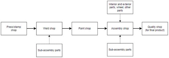
Figure 1.
A general automotive manufacturing process.
The first phase in the automotive production process (referring to Figure 1) is pressing or stamping, which involves shaping and trimming the metal sheet with a pressing machine equipped with precise dies to make the required single part. These technique procedures desired pieces such as doors, fenders, chassis, pillars, aprons, hood, roof, etc. Piercing to produce holes in the pieces and bending to bend the appropriate section is also part of the procedure [14]. To create these parts, the dimensions and thickness of the metal sheet are customized based on the design, quality, safety, and cost considerations.
When the parts are ready, the procedure is followed by welding. The pieces are combined in this welding technique to form the body-in-white (BIW). The term BIW refers to the joining of the frame of an automotive body [14,15]. Special welding jigs are used to assist in the process of holding the component, maintaining process precision and accuracy, and balancing the parts. To produce a high-quality product, the approach may utilize methods such as welding or hemming.
The next step is to paint the BIW. In general, the technique comprises electrodeposition and base-top-clear coating to resist corrosion and provide a pleasant look. According to a literature study [16], some manufacturers may apply a technique such as a sealer in the paint shop. Section 2.2. describes this process in detail.
The next stage is to assemble all of the parts (not only from the main process but also from the vendors and suppliers) into BIW, including the wheel, interior and exterior parts, engines, and sub-assembly parts (e.g., door parts, etc.). This process is also difficult since it concerns logistics, working space, workability, takt time, safety, etc. Following this step, the final stage, a quality check is required to ensure that the finished products perform properly and look good before they are released to the market. This final quality check is the manufacturer’s last inspection. In the practical aspect, the quality checks are also performed in every process before delivering to the next phase; this method is carried out to eliminate defects created by each stage; this word refers to built-in quality.
2.2. Waste Heat Emissions in the Process of a Paint Shop
The painting operation, which is one of the essential stages in the automotive manufacturing process, provides a pleasing look and gives the body-in-white (BIW) and other parts an attractive appearance and appeal, as well as protection against weather and corrosion. In this operation, several complicated processes occur one by one, starting with cleaning (after the welding process) and ending with quality inspections (before transferring the body to the assembly shop) [16].
The painting process in the automotive industry encompasses numerous factors, including both physical and chemical processes. Figure 2 illustrates the general serial process in the paint shop. Pretreatment, cathodic electrodeposition, sealer (applied by only a few manufacturers in this stage), coating, and quality control are the primary processes in this shop [7,16].
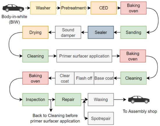
Figure 2.
The steps of a process in the automotive paint shop, adapted from [16].
In the first step, a washer is used to clean the BIW from dirt, residual welding process and to degrease the oil used in the pressing/stamping and welding phases [17]. The next step is pretreatment, which is required for corrosion protection and offers the best adhesion for electrodeposition coatings [16]. Pretreatment is divided into many phases, beginning with degreasing, rinsing, activation, phosphating, rinsing, and ending with demineralized water rinsing [16,18,19]. The course of pretreatment is determined by the cleanliness of the BIW entering the process line and adding a phosphating layer. The process uses the dipping method and operates with a specific temperature range which is given in Table 1. The operating temperature range may vary based on the applied material. According to the report [20], the phosphating process is intended to deposit a thin, dense, and uniform conversion layer on the cleaned and prepared metal surface on the BIW.

Table 1.
Operating conditions in the pretreatment process, adapted from [17].
Cathodic electrodeposition (CED) is another coating used in the automotive process that provides good corrosion protection. CED is currently widely used, and the primary advantages derived from the electrodeposition process are associated with, eliminating the need for iron, zinc, or aluminum usage, associated with inorganic pretreatment, as well as the chemical nature of the resins [16,18]. The dipping method is used in CED, and typical operating conditions of this process are provided in Table 2.
Table 2.
Operating conditions of typical CED tanks, adapted from [16].
Following the application of CED, a drying process with the help of a baking oven is required. To cure the electrocoating, the oven is set to a specific operating temperature (ranging between 443.15 and 453.15 K [16]). Dirt, craters, or other film thickness issues related to defects may appear after this process, so sanding process is required to eliminate this problem before moving on to the next stage of the appearance process. A few automotive manufacturers use this schematic layout (see Figure 2), and the process adds some sealers to prevent the entering of water and dust, to have good noise cancellation, to prevent a serious problem that may lead to corrosion, and to be a rustproofing.
The next step is to apply a paint coating to the exterior of the automotive body. In practice, depending on the color, there are three types of paint coats (i.e., solid or metallic). The paint coating here also requires the use of a baking oven to dry the paint material applied to the BIW. In a conventional way, the process is serial, with the paint material on BIW needing to be dried after application. During the paint curing after primer-coat application, the oven is set at the temperature of ca. 423.15–448.15 K depending on the desired operating time [16]. For the base and clear coats, the common operating condition based on a study [16] is described in Table 3. The temperature range of curing for primer, base, and clear coats is determined by the material used in the process and the manner of coating.
Table 3.
Operating conditions for drying and curing processes, adapted from [16].
According to reported research [16], there is an improvement in reducing the use of baking ovens by implementing the wet-on-wet application. The wet-on-wet primer and base coat application is tempting, but the primer and base paint materials must be sufficiently compatible. The application can be used for the base and clear paint coating using the same manner. One technique has been established by introducing a wet-on-wet-on-wet (so-called 3 wet [21]) system in which primer, base, and clear paint materials are applied in serial without drying it [17]. The same layers can now be applied one after the other without the need for baking in between thanks to advancements in coatings and rheology science. This advancement gives automakers the option of eliminating the primer spray booth and oven, resulting in lower energy consumption and CO2 emissions [7,16,22]. It is reported that with this technology, the 3-wet system has the potential to be cost-effective and ecologically rigorous, as well as produce a lasting, high-quality painted automotive body [17]. Figure 3 illustrate the evolution of the painting process for a better understanding.
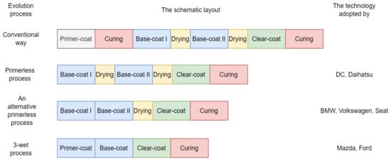
Figure 3.
The evolution of the painting process, adapted from [7,16].
Figure 3 shows the process layout and the elimination of paint drying and curing (oven). Despite the fact that this procedure is tempting for decreasing oven usage, the paint substance must dry at the end of the operation. It indicates that the bake oven is still operational. After all the operations are completed, the colored BIW must be examined (quality checked) before proceeding to the next stage, the assembling shop.
Since the above-mentioned complex system in a paint shop requires a specific temperature to run the process, such as the pretreatment, CED, and the paint coats, it appears that waste heat emission from this industry may occur. The potential waste heat sources in automotive paint shops are classified based on elementary processes in Table 4. The temperature generated by the process varies. Many potential waste heat sources appear to be recoverable, and the sustainable process of the factory can be therefore improved. In this case, the use of waste heat recovery can result in lower production costs and a lower environmental impact, especially for manufacturing processes that require heat all year, such as the paint shop.
Table 4.
Potential waste heat sources in the paint shop.
Baking ovens are often employed in this procedure to dry the material following the CED, primer, and topcoat processes. The operating condition of this oven is sensitive in order to produce the required temperature. Nonetheless, it has been discovered that waste heat release may exist since heat confinement in the baking oven or drying is typically poor. Waste heat might be disastrous in this paint shop, as it could heat up and disrupt the process as well as the working space where the factory staff is working.
3. Methodology
3.1. The Model of Waste Heat Recovery Employing ORC and TES
In the proposed system, the ORC system as waste heat recovery for floating heat (waste heat) from the bake oven may be promising for the application. Nevertheless, from the operating characteristic of the oven, it appears that the fluctuation of released heat may occur which is dependent on the specified operating temperature as well as the duration of the drying process. In such automotive manufacturing, there might be two or three shifts, and the machines are not operated in accordance with energy management (i.e., energy saving) between these shifts. For these reasons, using the TES device coupled with the ORC system will be advantageous. The TES is installed to store released waste heat and maintain the continuous operation of the ORC system. Due to space constraints, it may be preferable that the TES and heat exchanger (i.e., ORC evaporator) are put directly on the oven (not designed as a separate device). In this case, the heat exchanger combined with TES is called TES-evaporator.
An article [23] discussed the analogy of a heat exchanger inside an automotive paint oven. The oven is made up of many different zones based on temperature range and heat release. In this case, homogeneous heat flow distribution is important for drying and curing purposes, as well as the influence of thermal radiation. The suggested system in Figure 4 may be developed using the analogy of the automotive bake oven. Figure 4 shows the copper pipes wrapped around the outer layer of the drying and curing devices (bake oven). It is also found in practical aspect, i.e., that the heater of the oven is located in the middle of the working area, and the inlet and outlet of the pipes are located at both ends and the middle of the area, respectively. The red box in Figure 4 illustrates a novel configuration of the proposed integrated schematic system (TES-evaporator). The TES-evaporator is installed on the outside layer of the drying or curing chamber (baking oven). The purpose of putting TES materials within this TES-evaporator is to store thermal energy so that if the main operation of the painting process stops or take a break for a while, the ORC can continue its operation for a while until the main process resumes. The selected TES material used in this analysis are described in the following section (see Section 3.2).
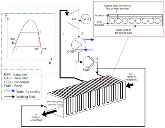
Figure 4.
A schematic layout of investigated waste heat recovery system employing TES and ORC.
For the waste heat recovery ORC system, the schematic layout and temperature-entropy diagram are illustrated in Figure 4. In this s configuration, the working fluid is pumped to the TES-evaporator (a liquid heater and an evaporator before entering the expander). The working fluid inside the cycle is evaporated to a saturated vapor (just altering the phase). Therefore, the superheater is not required to be installed. The working fluid is then expanded through the expander, which the shaft drives the generator to generate power (electricity). After that, the working fluid must be condensed in the condenser and pumped again to the evaporator of this closed-loop system. The selection of suitable working fluid for the ORC system is explained in the following section (see Section 3.2).
The computational investigation of the proposed system employs thermophysical properties libraries, i.e., CoolProp [24]. Thereby, the specific enthalpy and other thermal properties of the organic working fluid may be estimated for different operating conditions of the ORC system. Therefore, using the enthalpy change of each process within the closed-loop system, and by multiplying it by working fluid mass flow rate (which is determined based on energy balance), the power of pump and expander, the heat transfer rate of evaporator and condenser can be modeled, as well as the overall efficiency of the cycle can be computed using Equations (1)–(5),
where P, , , h, and η represent the power, heat transfer rate, mass flow rate, enthalpy, and efficiency, respectively. The subscripts EXR, CDS, PMP, HE, is, and wf describe the expander, condenser, pump, TES-evaporator, isentropic, and working fluid, respectively. The subscript of numbers at the enthalpy indicates the process (referring to Figure 4).
Some assumptions were made in this preliminary study, including steady-state operating conditions, and no change of kinetic and potential energy of the stream in the heat exchanger and the condenser. The TES-evaporator temperature in this study was simulated in the range of 343.15–373.15 K. The simulation procedure in this preliminary study was computed using MATLAB with the computation steps of ΔT1 = 1 K. According to an Indian primer oven research [25], the heat recovery from the exhaust of a primer oven in a paint shop was investigated via a computational fluid dynamic (CFD) model. As a result, in this article, it was assumed that a similar heat transfer rate of ca. 800 kW can be recovered from the oven. What is more, heat losses of 1% during heat transfer were taken into account. The cooling source was the water in the condenser which has a temperature of 308.15 K. The internal efficiency of the expander and pump was set at 0.8 and 0.7, respectively, based on the research articles and books reporting the internal efficiency ranges for different types of turbo and volumetric pumps and expanders [26,27,28,29,30,31].
3.2. Selection of the TES Materials
There are several types of TES materials characterized by physical phenomena (e.g., thermal, or chemical phenomenon), heat types (e.g., sensible, latent, etc.), and a storage medium (e.g., liquid, solid, solid–solid, liquid–gas, solid–solid, etc.) [32,33,34]. Furthermore, the suitable selection of TES material in relation to the suggested schematic arrangement presented in Figure 4 is needed. Figure 4 shows the primary process, in which the paint operation was carried out in an isolated working area to avoid dust and other chemical compounds that might disrupt the main process and result in poor product quality. As a result, only a few selected materials were employed in this study, such as selected solid type materials (e.g., Monel metals, stainless steel, stone, and bricks), as it was indicated in Table 5. The TES characteristic was determined by the material’s specific heat capacity, which varies with the temperature. Differential scanning calorimetry (DSC) may be used to assess the specific heat capacity of the thermal energy storage material. Equation (6) describes the general polynomial equation for the specific heat capacity of materials which is utilized to compute the stored thermal energy in Equation (7),
where C, T, Q, V, , L, A, and ΔT represent specific heat capacity, temperature, heat, volume, density, length of TES, the cross-section area of TES, and the temperature difference, respectively. The subscripts ST and SR represent the storage and surround.
Table 5.
Selected TES materials and its properties.
The specific heat capacity of selected materials in this study is presented in Table 5. These data were collected from several experimental investigations [35,36,37,38,39] while Equation (6) can be used to calculate the specific heat capacity of material using data (i.e., C0 and C1) reported in Table 5.
Assuming that the heat transfer rate during TES device discharging was the same as that of the TES-evaporator (see, Equation (8)), therefore, the efficiency of the stored thermal energy and the charging–discharging duration can be calculated using Equations (9)–(11),
where is charging/discharging times. The subscripts of CH and DE represent charging and discharging processes, respectively.
The dimensionless mass parameter (ζ(T)) of thermal energy storage material (given by Equation (12)) can be applied for sizing the TES used to waste heat recovery as an assessment parameter that,
where m is the mass. Since the utilization of waste heat in this automotive manufacturing employs the technology of ORC, the selection of working fluid is a key issue. The conditions related to the working area and the main operation at the paint shop should be taken into account. The paint shop has a complex and sophisticated operating condition with significant restrictions related to applied substances. These substances should be non-hazard, non-flammable, and non-toxic, while the process is isolated from the outside to avoid dust or contamination by the other components. For these reasons the working fluids for the ORC system modeled in this investigation are chosen based on their critical temperature (being less than 450 K), triple point temperature (being greater than 150 K). What is more, the selection was limited only to modern, safe, and environmentally friendly working fluids having a low global warming potential (GWP) and ozone depletion potential (ODP), being less flammable and hazardous (e.g., toxicity). Based on the criteria mentioned, R1233zd(E) and R1234ze(E) were chosen as working fluids in the analysis, with the essential parameter data reported in Table 6. The thermal properties of the above-mentioned working fluids selected for further analysis were taken from the thermophysical properties library, i.e., CoolProp [24].
Table 6.
Selected working fluids and their most important parameters.
4. Results and Discussion
4.1. The Net Power Output and Efficiency of the ORC System
Figure 5 presents the simulation findings for the ORC’s input and output powers based on chosen working fluids (R1233zd(E) and R1234ze(E)). Figure 5a displays the input power (pump power) ranges in the PPMP-T1 diagram, whereas Figure 5b illustrates the output power (expander power) ranges in the PEXR-T1 diagram. The obtained findings show that, when compared to R1234ze(E), R1233zd(E) as the working fluid inside the cycle requires less power to operate the pump and produces more power from the expander (at a particular temperature range).
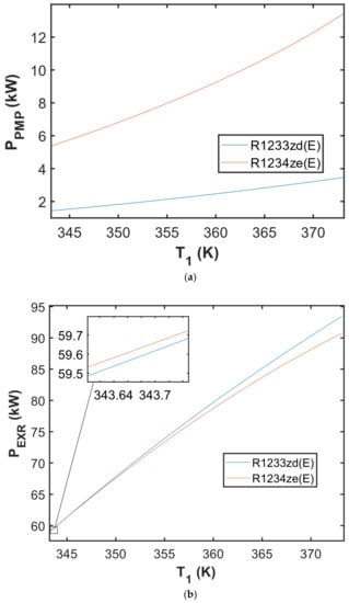
Figure 5.
The obtained result of (a) power of pump in the PPMP—T1 diagram; (b) power of expander in the PEXR—T1 diagram simulated with the ΔT1 = 1 K.
Figure 5a shows that at a TES-evaporator temperature of 373.15 K, the ORC utilizing R1234ze(E) requires a power input of 13.43 kW to operate the pump, whereas the cycle using R1233zd(E) requires an input power of 3.46 kW. The cycle utilizing R1233zd(E) produces 2.71 kW more power than the cycle using R1234ze(E) at the same TES-evaporator temperature. It appears that in a specific temperature range (shown by the enlarged box in Figure 5b), the expander using R1234ze(E) produces more power than the expander using R1233zd(E). However, the power generated by R1233zd(E) at this temperature range is negligible; thus, it can be inferred that the expander employing R1233zd(E) or R1234ze(E) generates almost the same amount of power at the TES-evaporator temperature range of 343.15–350 K.
In this investigation, the expander appears to provide little power (below 100 kW). According to research publications [42,43,44,45], the volumetric expander and turbo expander appear to be viable solutions for waste heat recovery in the automotive paint industry. Many selection factors must be considered in small ORC expanders, such as the economic aspect, market availability, reliability, maintainability, and other relevant technical issues. Because the confinement area of the automotive paint shop is crucial, technical issues such as sealing, and leakage are the primary considerations during installation, maintenance, and operation of ORC-based waste heat recovery system to prevent working fluids from flowing out of the ORC installation to the oven. If the low boiling working fluid vapor leakage will occur from the ORC system (i.e., the ORC system is not hermetically sealed), the working fluid vapor can mix with the air entering the oven where the primary painting process is proceeding and result in the undesirable defect of the painted BIW. Furthermore, following the quality check, paint repair may be required, which will result in higher costs of the painting. For these important reasons, a fully hermetically sealed expander-generator set must be installed in the ORC system. Among the volumetric-type expanders, the screw expander appears to be promising in this application since based on the data reported in some articles [42,43,45,46], it fits well to the power range under consideration and can be hermetically sealed.
During the preliminary investigation, the net output power of the waste heat recovery system can be estimated. This net output power may be calculated by subtracting the power of the pump from expander power. Another measure used to describe the performance of the waste heat recovery as power generation was the overall efficiency of the cycle, which indicates the net output power of the system per input heating power. Figure 6a illustrates the net output power of the waste heat recovery using ORC for automotive bake oven (referring to Figure 4) in the Pnet-T1 diagram. The ORC utilizing R1233zd(E) appeared to provide higher power at the same TES-evaporator temperature. As the input power was the same (assuming that the waste heat is entirely recovered), the overall efficiency of the ORC followed a similar curve in the η-T1 diagram. The application of R1233zd(E) provided a higher overall efficiency than in the case of R1234ze(E). Figure 6 showed that the net output power and overall efficiency of the ORC system had a consistent gap in the TES-evaporator temperature range of 343.15–350 K. The gaps widened when the TES-evaporator temperature rose over 350 K.
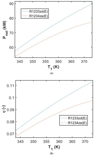
Figure 6.
The obtained result of (a) net output power in the Pnet—T1 diagram; (b) ORC efficiency in the η—T1 diagram simulated with the ΔT1 = 1 K.
The use of R1233zd(E) working fluid in the ORC system s also beneficial to the environment as this fluid has a low GWP (GWP = 1). Furthermore, this working fluid may be suitable for the paint shop due to the absence of flame propagation and lower toxicity in accordance with the ASHRAE safety standard (referring to Table 6). As previously mentioned, the use of R1233zd(E) as working fluid in the ORC system seems to be promising in the case of application of this waste heat recovery system in the automotive paint shop (baking oven), as it may generate more power than in case of R1234ze(E). It appears that the TES-evaporator plays a critical part in absorbing waste heat from the oven. Because the investigated system (referring to Figure 4) utilizes the TES material in the TES-evaporator, the sizing is discussed in more detail in the following section (Section 4.2).
4.2. Sizing TES for TES-Evaporator
The obtained modeling results related to the TES-evaporator are drawn in Figure 7. This figure illustrates the modeling findings for different working fluids and selected solid materials employed as thermal energy storage materials for the adjustment of the dimensionless thermal energy storage material mass parameter (ζ(T1)) (see Section 3.2) and TES-evaporator temperature at the outlet (T1). The result allowed us to compare and estimate the amount of TES materials that have to be used in the TES system. The value of ζ(T1) parameter indicates the mass of the TES material required to preheat and evaporate 1 kg of low boiling working fluid applied in the ORC system as an example. Figure 7 illustrates the simulated outcome, which shows that the lower value of ζ(T1), the less mass of TES material is required to evaporate working fluid inside the ORC system.
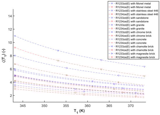
Figure 7.
A ζ(T1)—T1 diagram of different working fluids and TES materials simulated with the ΔT1 = 1 K.
Based on the investigation, the obtained results of ζ(T1) parameter ranges between 1.65 and 10.99 which the highest result of ζ(T1) = 10.99 is obtained for Monel metal as TES material and R1233zd(E) as working fluid inside the ORC system with the TES-evaporator temperature at 343.15 K. Moreover, the lower result of ζ(T1) = 1.65 is the combination of granite as TES material and R1234ze(E) as working fluid with the TES-evaporator temperature at 373.15 K. Overall, the combination of Monel metal and R1233zd(E) performs the highest sizing parameter while granite and R1234ze(E) is the lowest one, as shown in Figure 7.
In this study, the enthalpy change of the TES-evaporator steadily decreases while the enthalpy change of the preheater gradually increases. This situation occurs in response to the saturated curve’s boundary condition. The enthalpy changes of the combination preheater and evaporator using the TES material is found to marginally increase. Furthermore, the specific heat capacity of the chosen TES material increases dramatically. With these conditions in effect, the result in Figure 7 demonstrates that the ζ(T1) tends to drop. A similar condition in decreasing the ζ(T) was also found in the previous study of the authors for different TES materials and working fluids [47].
Figure 7 shows that the slope of ζ(T1) varies depending on the combination (TES materials and working fluids). In this example, the slope of the selected working (R1233zd(E) and R1234ze(E)) paired with the chosen TES material in the ζ(T1) range of 1.65–4 appears to be relatively not steep compared to ζ(T1) > 4 (referring to Figure 7). It demonstrates that there are not likely many significant variations in the size parameter in these TES materials with 1.65 < ζ(T1) < 4.
Considering Equations (10)–(12), which the mass flow rate of the discharging and charging are the same value (i.e., indicating with ), therefore, the real size of TES-evaporator can be determined using Equation (13),
Equation (13) gives the information concerning the true size of the TES-evaporator which is represented with the mass of thermal energy storage material (). Based on this equation, the true size of the TES-evaporator is gradually reducing, given that the required charging/discharging time is constant dependent on the gap/shift change/break timings (which follows the same trend as it is presented in Figure 7).
A complete mechanical and structural study is interesting to be considered for future work on the TES-evaporator use in the paint shop. Because the current baking was been built with fixed mechanical and physical quantities, the TES material used in the suggested system (see Figure 4) was essential. The addition of TES materials to the top of the baking oven will change its structure as well as other mechanical and physical characteristics.
The above-mentioned waste heat recovery to electricity in a paint shop might be an alternate solution for an automotive factory. In this case, electricity, which is considered as a high-quality energy, may be produced from the waste heat and utilized to electrify auxiliary installations such as for example fans, lamps, automatic control systems, office supplies, equipment, and other items, potentially lowering power usage. Therefore, this generated waste heat is recovered by means of ORC and then reused for covering the own needs of the production process not directly (i.e., as recuperated low-quality heat) but indirectly as high-quality electricity. Because the primary process requires a significant amount of process heat, additional research into waste heat recovery for recuperation purposes may be worthwhile. However, several important factors which are significantly limiting the possibility of recuperation, heat recovering, and directing it back to the main process to cover its own needs must be considered. Since the main process may be involving critical parameters in the complex system (such as pH, dump frequency, chemical reaction, dipping time, conductivity, and so on [16]), this recuperation or reheating may result in more structural defects and issues in the paint shop, where the quality is critical in the appearance and coatings for corrosion of BIW.
5. Conclusions
In this work, a model of ORC system combined with TES-evaporator to recover waste heat from a baking oven in an automotive paint factory was constructed and implemented. The model determines how much net output power can be recovered from the baking oven via the ORC system and computes the corresponding efficiency of the ORC system. The TES material appears to be promising to be applied in the suggested system to maintain the ORC system operation steady as there is a break period (e.g., changing the shift workers, maintenance, lunch/dinner breaks, etc.) in the vehicle manufacturer’s operating system.
The results of this modeling simulation demonstrate that the ORC system using R1233zd(E) generates more expander power and consumes less pump power than R1234ze(E), can be seen in the power (P) and TES-evaporator temperature (T1) diagram, as illustrated in Figure 5. Overall, the ORC system utilizing R1233zd(E) as the working fluid generates more net output power and has a higher overall efficiency than the system utilizing R1234ze(E), as illustrated in the variation of the net output power (Pnet) and ORC efficiency (η) vs. T1 diagrams (which is depicted in Figure 6). The design of the described system should consider the selection of appropriate TES materials featuring good and extended thermal storage. Since there was no fixed size, mechanical, and physical properties of the oven, and the general case was studied in this paper, therefore sizing parameter was presented in this study. This heat storage mass size parameter, referring to the variation of the dimensionless storage mass parameter (ζ(T1)) vs. T1 diagram in Figure 7, might assist scientists and engineers while designing and constructing an effective TES-evaporator for waste heat recovery in an automotive paint shop. To determine the true size of TES-evaporator, Equation (13) can be used for the practical purpose in developing and estimating the application of TES material. As an example, 800 kW of generated waste heat from the oven can be recovered to produce the net power of 53–89 kW with the overall ORC efficiency of 6.7–11% as illustrated Figure 6. In this study, it appears that representing the obtained results in P-T1, η-T1, ζ(T1)-T1 diagrams as the trendline of the overall ORC efficiency, power and the heat storage mass size parameters can be observed as function of the TES-evaporator temperature which may be useful in a practical standpoint.
According to the findings of this study, there is a potential for improvements in the schematic layout process, the selection of proper TES materials and organic working fluids, the selection of expanders and pumps for ORC systems, and the configuration of efficient TES-evaporators to recover waste heat in the automotive paint shop. Furthermore, the development of a combined and integrated system in this field would be of particular interest.
Author Contributions
Conceptualization, methodology, software, formal analysis, investigation, data curation, writing—original draft preparation, writing—review and editing, visualization, S.D.; validation, supervision, writing—review and editing P.K. and B.R. All authors have read and agreed to the published version of the manuscript.
Funding
This work was supported by NAWA STER Program Internationalization of Wroclaw University of Science and Technology Doctoral School.
Data Availability Statement
Not applicable.
Acknowledgments
The authors would like to thank Giovanni Manente, Adriano Sciacovelli, and Christos Markides for the invitation to publish this article.
Conflicts of Interest
The authors declare no conflict of interest.
Nomenclatures
| A | Total area of thermal energy storage (m2) |
| C | The specific heat capacity (J/kg∙K) |
| h | The specific enthalpy (J/kg) |
| L | Total length of thermal energy storage (m) |
| m | mass (kg) |
| Mass flow rate (kg/s) | |
| P | Power (Watt) |
| T | Temperature (K) |
| Q | Heat transfer (J) |
| Heat transfer rate (Watt) | |
| V | Volume (m3) |
| Greek letters: | |
| Efficiency (-) | |
| Density (kg/m3) | |
| Charging/discharging times (s) | |
| Dimensionless storage mass parameter (-) | |
| Subscripts: | |
| 1,2,3,4 | Process in the cycle |
| CDS | Condenser |
| CH | Charging |
| DE | Discharging |
| EXR | Expander |
| HE | TES-evaporator |
| is | Isentropic process |
| ORC | Organic Rankine cycle |
| PMP | Pump |
| re | Real process |
| SR | Surroundings |
| ST | Storage |
| WF | Working fluids |
| Abbreviations: | |
| BIW | Body-in-white |
| CED | Cathodic electrodeposition |
| CFD | Computational fluid dynamic |
| CSP | Concentrated solar power |
| DSC | Differential scanning calorimetry |
| GWP | Global warming potential |
| ODP | Ozone depletion potential |
| ORC | Organic Rankine cycle |
| RTO | Regenerative thermal oxidizer |
| TES | Thermal energy storage |
| VOC | Volatile organic compound |
References
- Kolasiński, P.; Rogosz, B. A review on industrial waste heat sources and recovery methods. In Proceedings of the 32nd International Conference on Efficiency, Cost, Optimization, Simulation and Environmental Impact of Energy Systems, ECOS 2019, Wrocław, Poland, 23–28 June 2019. [Google Scholar]
- Tchanche, B.F.; Lambrinos, G.; Frangoudakis, A.; Papadakis, G. Low-grade heat conversion into power using organic Rankine cycles—A review of various applications. Renew. Sustain. Energy Rev. 2011, 15, 3963–3979. [Google Scholar] [CrossRef]
- Lecompte, S.; Huisseune, H.; van den Broek, M.; Vanslambrouck, B.; de Paepe, M. Review of organic Rankine cycle (ORC) architectures for waste heat recovery. Renew. Sustain. Energy Rev. 2015, 47, 448–461. [Google Scholar] [CrossRef]
- Fatigati, F.; Vittorini, D.; Wang, Y.; Song, J.; Markides, C.N.; Cipollone, R. Design and Operational Control Strategy for Optimum Off-Design Performance of an ORC Plant for Low-Grade Waste Heat Recovery. Energies 2020, 13, 5846. [Google Scholar] [CrossRef]
- Saadon, S.; Mohd Nasir, N.A. Performance and Sustainability Analysis of an Organic Rankine Cycle System in Subcritical and Supercritical Conditions for Waste Heat Recovery. Energies 2020, 13, 3035. [Google Scholar] [CrossRef]
- Giampieri, A.; Ling-Chin, J.; Taylor, W.; Smallbone, A.; Roskilly, A.P. Moving towards low-carbon manufacturing in the UK automotive industry. Energy Procedia 2019, 158, 3381–3386. [Google Scholar] [CrossRef]
- Giampieri, A.; Ling-Chin, J.; Ma, Z.; Smallbone, A.; Roskilly, A.P. A review of the current automotive manufacturing practice from an energy perspective. Appl. Energy 2020, 261, 114074. [Google Scholar] [CrossRef]
- Iglauer, O.; Zahler, C. A New Solar Combined Heat and Power System for Sustainable Automobile Manufacturing. Energy Procedia 2014, 48, 1181–1187. [Google Scholar] [CrossRef]
- Zahler, C.; Iglauer, O. Solar Process Heat for Sustainable Automobile Manufacturing. Energy Procedia 2012, 30, 775–782. [Google Scholar] [CrossRef][Green Version]
- Hanafizadeh, P.; Khaghani, A.; Shams, H.; Saidi, M.H. Heat recovery of exhaust gas in automotive paint ovens. In Proceedings of the 23rd International Conference on Efficiency, Cost, Optimization, Simulation, and Environmental Impact of Energy Systems, ECOS 2010, Lausanne, Switzerland, 14–17 June 2010; Volume 5, p. 381. [Google Scholar]
- Chang, D.-S.; Cheng, K.-P.; Wang, R. Developing low temperature recovery technology of waste heat in automobile factory. Energy Sci. Eng. 2018, 6, 460–474. [Google Scholar] [CrossRef]
- Trimpe, J., Jr. Waste Heat Recovery of Industrial Regenerative Thermal Oxidizer (RTO), a Case Study. Master’s Thesis, University of Kentucky, Lexington, KY, USA, 2021. [Google Scholar]
- Adamkiewicz, A.; Nikończuk, P. Waste heat recovery from the air preparation room in a paint shop. Arch. Thermodyn. 2019, 40, 229–241. [Google Scholar] [CrossRef]
- Grujicic, M.; Sellappan, V.; He, T.; Seyr, N.; Obieglo, A.; Erdmann, M.; Holzleitner, J. Total Life Cycle-Based Materials Selection for Polymer Metal Hybrid Body-in-White Automotive Components. J. Mater. Eng. Perform. 2009, 18, 111–128. [Google Scholar] [CrossRef]
- Hirsch, J. Recent development in aluminium for automotive applications. Trans. Nonferrous Met. Soc. China 2014, 24, 1995–2002. [Google Scholar] [CrossRef]
- Streitberger, H.-J.; Dossel, K.-F. Automotive Paints and Coatings; John Wiley & Sons: Weinheim, Germany, 2008; ISBN 3527309713. [Google Scholar]
- Akafuah, N.K.; Poozesh, S.; Salaimeh, A.; Patrick, G.; Lawler, K.; Saito, K. Evolution of the Automotive Body Coating Process—A Review. Coatings 2016, 6, 24. [Google Scholar] [CrossRef]
- Talbert, R. Paint Technology Handbook; CRC Press: Boca Raton, FL, USA, 2007; ISBN 1420017780. [Google Scholar]
- Li-ping, C. Analysis of the Influence of Car Body Structure on the Pretreatment & Electrophoresis Process. Shanghai Coat. 2011, 8, 27–28. [Google Scholar]
- Sankara Narayanan, T.S.N. Surface pretretament by phosphate conversion coatings—A review. Rev. Adv. Mater. Sci. 2005, 9, 130–177. [Google Scholar]
- Hayashi, H.; Ishii, M. Development of 3-Wet Paint System with Improved Appearance-Paint Design Based on Transfer Mechanism of Unevenness from Under Layers; SAE Technical Paper; SAE International: Warrendale, PA, USA, 2014. [Google Scholar]
- Schoff, C.K. Craters and Other Coatings Defects: Mechanisms and Analysis. In Protective Coatings; Wen, M., Dušek, K., Eds.; Springer International Publishing: Cham, Switzerland, 2017; pp. 403–425. ISBN 978-3-319-51627-1. [Google Scholar]
- Rao, P.P. A heat exchanger analogy of automotive paint ovens. Appl. Therm. Eng. 2013, 61, 381–392. [Google Scholar] [CrossRef]
- Bell, I.H.; Wronski, J.; Quoilin, S.; Lemort, V. Pure and Pseudo-pure Fluid Thermophysical Property Evaluation and the Open-Source Thermophysical Property Library CoolProp. Ind. Eng. Chem. Res. 2014, 53, 2498–2508. [Google Scholar] [CrossRef]
- Phad, C.B.; Jaware, V.B. Analysis of heat recovery from primer oven exhaust in paint shop. Int. J. Eng. Res. Technol. 2017, 6, 250–257. [Google Scholar]
- Smith, I.K.; Stosic, N.; Kovacevic, A. Power Recovery from Low Grade Heat by Means of Screw Expanders; Elsevier: Amsterdam, The Netherlands, 2014; ISBN 1782421904. [Google Scholar]
- Hammerschmid, A.; Stallinger, A.; Obernberger, I.; Piatkowski, R. Demonstration and evaluation of an innovative small-scale biomass CHP module based on a 730 kWel screw-type steam engine. In Proceedings of the 2nd World Conference and Exhibition on Biomass for Energy, Industry and Climate Protection, Rome, Italy, 10–14 May 2004. [Google Scholar]
- Öhman, H.; Lundqvist, P. Screw expanders in ORC applications, review and a new perspective. In Proceedings of the 3rd International Seminar on ORC Power Systems, Brussels, Belgium, 12–14 October 2015. [Google Scholar]
- Pawlik, M.; Strzelczyk, F. Elektrownie; Wydawnictwo Naukowe PWN: Warszawa, Poland, 2016; ISBN 978-83-01-18954-9. [Google Scholar]
- Hsu, S.-W.; Chiang, H.-W.D.; Yen, C.-W. Experimental Investigation of the Performance of a Hermetic Screw-Expander Organic Rankine Cycle. Energies 2014, 7, 6172–6185. [Google Scholar] [CrossRef]
- Nikolov, A.; Brümmer, A. Investigating a Small Oil-Flooded Twin-Screw Expander for Waste-Heat Utilisation in Organic Rankine Cycle Systems. Energies 2017, 10, 869. [Google Scholar] [CrossRef]
- Kolasiński, P. Experimental and modelling studies on the possible application of heat storage devices for powering the ORC (organic rankine cycle) systems. Therm. Sci. Eng. Prog. 2020, 19, 100586. [Google Scholar] [CrossRef]
- Sarbu, I.; Sebarchievici, C. A Comprehensive Review of Thermal Energy Storage. Sustainability 2018, 10, 191. [Google Scholar] [CrossRef]
- Dincer, I.; Rosen, M. Thermal Energy Storage: Systems and Applications; John Wiley & Sons: Hoboken, NJ, USA, 2002; ISBN 0471495735. [Google Scholar]
- Douglas, T.B.; Dever, J.L. Enthalpy and specific heat of four corrosion-resistant alloys at high temperatures. J. Res. Natl. Bur. Stand. 1955, 54, 15–19. [Google Scholar] [CrossRef]
- Abdulagaov, I.M.; Abdulagatova, Z.Z.; Kallaev, S.N.; Omarov, Z.M. Heat-capacity measurements of sandstone at high temperatures. Geomech. Geophys. Geo-Energy Geo-Resour. 2019, 5, 65–85. [Google Scholar] [CrossRef]
- Miao, S.Q.; Li, H.P.; Chen, G. Temperature dependence of thermal diffusivity, specific heat capacity, and thermal conductivity for several types of rocks. J. Therm. Anal. Calorim. 2014, 115, 1057–1063. [Google Scholar] [CrossRef]
- Kostowski, E. Przepływ ciepła; Wydawnictwo Politechniki Śląskiej: Gliwice, Poland, 2010. [Google Scholar]
- Pan, J.; Zou, R.; Jin, F. Experimental Study on Specific Heat of Concrete at High Temperatures and Its Influence on Thermal Energy Storage. Energies 2017, 10, 33. [Google Scholar] [CrossRef]
- Györke, G.; Deiters, U.K.; Groniewsky, A.; Lassu, I.; Imre, A.R. Novel classification of pure working fluids for Organic Rankine Cycle. Energy 2018, 145, 288–300. [Google Scholar] [CrossRef]
- Lemmon, E.; Huber, M.; McLinden, M. NIST Standard Reference Database 23: Reference Fluid Thermodynamic and Transport Properties-REFPROP, Version 9.1; National Institute of Standards and Technology: Gaithersburg, MD, USA,, 2013. [Google Scholar]
- Weiß, A.P. Volumetric expander versus turbine–which is the better choice for small ORC plants. In Proceedings of the 3rd ASME ORC Conference, Brussels, Belgium, 12–14 October 2015; pp. 1–10. [Google Scholar]
- Imran, M.; Usman, M.; Park, B.-S.; Lee, D.-H. Volumetric expanders for low grade heat and waste heat recovery applications. Renew. Sustain. Energy Rev. 2016, 57, 1090–1109. [Google Scholar] [CrossRef]
- Badr, O.; O’Callaghan, P.W.; Hussein, M.; Probert, S.D. Multi-vane expanders as prime movers for low-grade energy organic Rankine-cycle engines. Appl. Energy 1984, 16, 129–146. [Google Scholar] [CrossRef]
- Kolasiński, P. Application of volumetric expanders in small vapour power plants used in distributed energy generation—Selected design and thermodynamic issues. Energy Convers. Manag. 2021, 231, 113859. [Google Scholar] [CrossRef]
- Dumont, O.; Dickes, R.; Lemort, V. Experimental investigation of four volumetric expanders. Energy Procedia 2017, 129, 859–866. [Google Scholar] [CrossRef]
- Kolasiński, P.; Daniarta, S. Sizing the thermal energy storage (TES) device for organic Rankine cycle (ORC) power systems. In Proceedings of the MATEC Web of Conferences; EDP Sciences: Les Ulis, France, 2021; Volume 345. [Google Scholar]
Publisher’s Note: MDPI stays neutral with regard to jurisdictional claims in published maps and institutional affiliations. |
© 2022 by the authors. Licensee MDPI, Basel, Switzerland. This article is an open access article distributed under the terms and conditions of the Creative Commons Attribution (CC BY) license (https://creativecommons.org/licenses/by/4.0/).