1. Introduction
Fuel cells are an emerging power generation technology for various applications, such as power stations and vehicles. The fuel cell converts hydrogen and air/oxygen to electricity through electrochemical reactions at its electrodes. A proton-exchange membrane fuel cell (PEMFC) has a membrane between the cathode and anode that only allows protons to cross. Because the process is highly efficient, silent, and environmentally friendly, it has become the focus of recent research and development [
1,
2,
3]. The energy conversion in a PEMFC strongly depends on the proton conductivity of the membrane. Increasing the moisture content in the membrane fosters proton movement and improves the performance of the fuel cell stack. However, too much water can saturate the channels and block the gas flow, while too little water leads to high proton resistance and membrane degradation. Therefore, water management is essential for optimizing the PEMFC performance [
4,
5,
6,
7,
8,
9,
10,
11]. This can be accomplished by humidifying the anode and cathode gases; however, studies have shown that the cathode gas dominates the anode gas. Thus, water management of the fuel cell membrane should focus on humidifying the supply of air/oxygen [
12,
13,
14].
Membrane humidifiers have low energy consumption and simple construction. The membrane has a porous structure that allows water particles to move from the wet side to the dry side while blocking undesired substances. Depending on the shape of the membrane, a membrane humidifier can be classified as planar or tubular. Tubular membrane humidifiers are commonly used for automotive applications because of their high efficiency. These humidifiers recirculate the cathode exhaust air, which has a high relative humidity, to humidify the supply air through a bundle of membranes. The moist air moves outside the bundle, and the dry air flows inside, normally in the opposite direction. Two manifolds at the ends of the humidifier collect the dry flow. The humidified gas is then supplied to the cathode and is circulated in the PEMFC system. The water transfer rate and relative humidity of the dry flow are important parameters that affect the humidifier performance. The system is subjected to various working conditions, and transient phenomena make water management difficult. Such changes affect the characteristics of the supply gas for the cathode. Therefore, understanding humidifier behavior under different operating conditions is critical to controlling the PEMFC [
15,
16].
Modeling the humidifier can help with understanding the factors that influence the supply gas characteristics and improving the PEMFC performance. However, balancing the complexity of the model for accuracy and straightforwardness for later integration in the PEMFC model is a challenging task. Bhatia et al. [
17] developed an analytical model for predicting the steady-state heat and mass transfer of both planar and tubular membrane humidifiers that considers the effects of vapor transport. Yu et al. [
18] built a static model of a planar membrane humidifier to investigate the effects of the operating conditions and membrane characteristics. Park et al. [
19] studied the dynamics of an external humidifier for a fuel cell system and developed a one-dimensional model of the mass transfer in membrane tubes that discretizes the volumes along the flow channels. Kang et al. [
20] used a two-dimensional model and experimental data to investigate the dynamics of a hollow-fiber membrane humidifier. Solsona et al. [
21] presented a dynamic model of a water-to-gas membrane humidifier that regulates the relative humidity of the cathode supply air. Fu et al. [
22] integrated a lumped-mass model of an external humidifier into a fuel cell system for humidity control. Some of the above models used discretization to evaluate the changes in the flow characteristics with the membrane geometry, which increased the computational time. Other models only considered the characteristics at the inlets and outlets, and they neglected the dynamics in the membrane channels. These models are more suitable for integration into the PEMFC model than complicated models.
None of the above models considers the manifolds of the humidifier, where water saturation may occur. Due to the high humidity of the supply air and temperature change, water could be formed in the manifolds, especially in the exiting one. The saturated water may block the air moving paths and affect the fuel cell performance. In this study, manifold dynamics were considered, which account for changes in the supply air characteristics in the humidifier manifolds and identify noticeable operating conditions that result in the water formation.
A lumped-mass model was developed for a hollow-fiber membrane humidifier, which is a type of tubular humidifier that consists of a heat and mass exchanger and two manifolds at the ends of the exchanger. The model provides a simple approach to capturing the heat and mass transfer phenomena in the humidifier components. It can be used to simulate the humidifier performance under different operating conditions and point out possible water saturation of the manifolds. It can help with understanding the dynamics of the PEMFC and developing a control strategy.
2. Model Description
2.1. Gas-to-Gas Membrane Humidifier
The humidifier should provide the desired amount of water vapor to the supply air under various conditions. Understanding the behavior of the humidifier is beneficial to designing and controlling the PEMFC system to maximize its performance. In this study, the effects of the operating mass flow rate, temperature, and relative humidity on the mass transport rate and characteristics of dry air at the humidifier outlet were investigated. In a PEMFC system, moist air from the cathode exhaust correlates with the supply air. Moist air interacts with dry air when the humidifier is integrated with the fuel cell stack. However, this study was focused on the humidifier. Thus, the humidifier operating conditions were predetermined and assumed independent of the fuel cell system so that their effects could be identified.
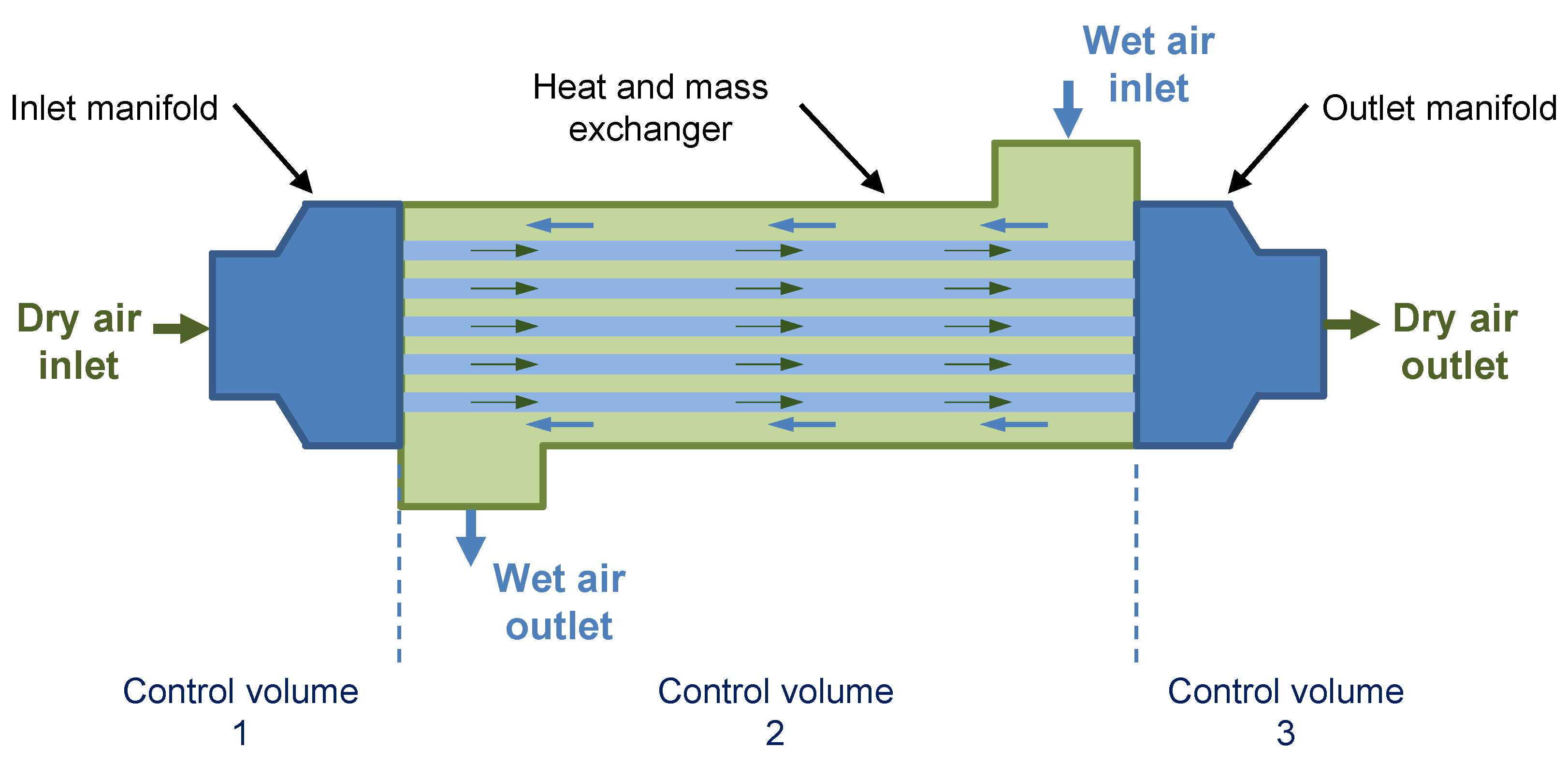
The humidifier was assumed to allow moist air to transfer water particles to dry air in a counter-flow setup. The main component is a bundle of porous membranes placed inside a cylindrical shell, as shown in
Figure 1. The membranes support vapor transport from a higher concentration surface to a lower concentration surface while preventing the transport of other substances. Moist air is exhausted from the cathode and pumped to the shell side of the humidifier. The dry air from the compressor moves in the bundle and gains humidity from the moist air. The two flows are arranged in opposite directions by four ports on two manifolds and on the shell. The two manifolds deliver the inlet flow on the dry side to the membranes and collect the outlet flows from the membranes.
The humidifier module was divided into three control volumes: (1) the inlet manifold that takes the supply air and distributes it to the membrane tubes; (2) the heat and mass exchanger, which includes the membrane bundle comprising tubes housed in a shell; and (3) the outlet manifold that exhausts the moist air from the humidifier. Control volume 1 was used to study the heat transfer from the internal flow to the manifold and outside ambient air. Control volume 2 was used to study the heat and mass transfers between the two flows. Similar to control volume 1, control volume 3 was used to study thermal transport phenomena. The output of control volume 1 was a dry flow, which was the input for control volume 2. The flow characteristics output by control volume 2 were the input parameters for control volume 3.
Table 1 describes the dimensions of the humidifier module, which were taken from the FC300-1660-10LP/HP humidifier of Perma Pure company [
23]. The humidifier was designed for a 5 kW PEMFC system and to work in both water-to-gas and gas-to-gas modes. The membrane characteristics were taken from the literature [
24].
2.2. Manifolds
The thermal energy of a manifold is affected by changes in the flow energy and heat loss to the environment. The characteristics of the manifold affect the temperature difference, which in turn influences the relative humidity of the flow. The mass of the manifold depends on the dimensions and density of the manifold material, which in turn influences the heat capacity and temperature of the manifold. The heat transfer from the flow to the inner surface of the manifold can be calculated by using the convective heat transfer coefficient and log mean temperature difference between the inlet and outlet temperatures. The energy balance in the manifold is given by:
The convective heat transfer coefficient between the inner surface of the manifold and the flow is determined according to the Nusselt number:
The Nusselt number depends on the flow conditions:
For the transition zone between laminar and turbulent conditions, interpolation can be used to calculate the Nusselt number. The Reynolds number
for the flow is given by:
The friction factor also depends on the flow conditions. For a fully developed laminar flow, the friction factor
is inversely proportional to the Reynolds number:
The log mean temperature difference can be calculated by using the manifold temperature and inlet and outlet temperatures of the dry flow [
25]:
The heat transfer of the internal flow can be used to determine the correlation between the outlet and inlet temperatures [
25]:
Solving the system of Equations (1), (8) and (9) gives the temperatures of the manifold and outlet flow. The flow temperature can be used to calculate the saturation pressure and relative humidity of the outlet air.
The saturation pressure depends only on the flow temperature:
where
for a temperature range of 0 to 100 °C.
The relative humidity of air is calculated as follows:
The pressure at the manifold outlet is determined from the head loss, which can be estimated from its correlation with the velocity and friction factor [
26]:
The flow characteristics from the inlet manifold are the inputs for the heat and mass exchanger, and the flow from the exchanger in turn supplies the input data for the outlet manifold. The two manifolds are modeled in the same way.
2.3. Heat and Mass Exchanger
2.3.1. Heat Transfer
Heat is transferred from the moist air outside the membrane tubes to the dry air inside. Because the inlet temperature is known under each operating condition, the outlet temperature of the heat transfer model can be estimated by using the effectiveness-number of the transfer units (NTU) method, which is applicable to different kinds of flow arrangements. In this case, the effectiveness of the counter-flow arrangement can be determined as follows [
27,
28]:
where
is the heat capacity ratio of the flows and takes a value from 0 to 1 [
28]:
The NTU for heat transfer analysis is calculated as follows:
The total thermal resistance
has three components: the convective thermal resistances at the inner and outer surfaces of the membranes and the conductive thermal resistance through the membrane structure:
The convective heat transfer coefficients for the inner surface and outer surface are determined by the Nusselt number, similar to the manifolds. The flow inside the membrane channels is laminar, while the flow characteristics on the shell side depend on the flow rate. The thermal conductivity is determined by the membrane material.
The heat transfer rate in the exchanger is given by:
The temperatures of the moist air and dry air at the outlet are:
The temperature is an important output for heat transfer analysis because it affects the relative humidity of the outlet flow, as given in Equation (11). The head loss in the exchanger is calculated in the same way as for the manifold, which is given in Equation (12). The relative humidity of the air in the channels also depends on the flow pressure.
2.3.2. Mass Transfer
A similar approach to heat transfer analysis was employed for analyzing the mass transfer in the exchanger. The effectiveness of the mass transfer was defined as the proportion of the actual vapor transfer rate to the maximum possible transfer rate [
28]:
The mass flow rate ratio is the proportion between the mass flow rates:
The
for mass transfer is given by:
The total mass resistance
is associated with the convective and conductive mass transfers of the membrane tubes:
The convective mass transfer coefficient is determined by the Sherwood number:
The Sherwood number for mass transfer in the membrane is given by [
28]:
The Schmidt number
and packing fraction
are:
The conductive mass transfer coefficient represents the diffusivity of vapor in the membrane, which was taken from experimental results [
24].
The mass transfer rate can then be calculated with the effectiveness:
The mass flow rates of the moist air and dry air at the outlet are given by:
The mass transfer rate can also be used to calculate the mass of the vapor and thus the specific humidity in each flow. Because the temperature, pressure, and specific humidity are given, the relative humidity of the dry flow at the outlet of the exchanger can then be determined by using Equation (11).
2.4. Simulation
The model was developed in MATLAB/Simulink environment. The program is suitable for creating analytical models with simulation blocks that link inputs and outputs of each block together in a system. The simulation was conducted to analyze operating conditions, geometric parameters, and transient responses of the humidifier, as described in
Table 2. The operating parameters are relative humidity, temperature, and mass flow rate of dry air and moist air. Effects of each parameter were studied when others are fixed. In addition, membrane length, thickness, and the number of membranes in the bundle were considered as design parameters. For humidifier dynamics, two cases were investigated, which are short-term operation and long-term operation. These simulations illustrate responses of the humidifier with stepwise rapid changes of input parameters and also stable working conditions. The mass transfer rate, heat transfer rate, and flow characteristics at the exits of the humidifier module are plotted to represent the humidifier performance.
3. Results and Discussion
3.1. Effects of Operating Conditions
In the first simulation case, all of the supply gas was recirculated after going through the cathode. The mass flow rates of the dry air and moist air had the same patterns.
Figure 2 plots the mass transfer rate in the humidifier over the mass flow rate of the moist air at different operating temperatures. The mass transport increased with the mass flow rate on both sides, and the trends were almost linear for a given temperature. Increasing the mass flow rate of the moist air made more water particles available for transfer to the dry side, which increased the mass transport. However, the relative humidity of the dry air was influenced by the mass flow rate in the opposite direction. When the mass flow rates increased on the dry and wet sides simultaneously, the humidity in the dry flow decreased, which indicates that the humidifier performance deteriorated. The increase in the vapor transport rate could not compensate for the increased flow rate of the dry air. Thus, the vapor fraction of the total air flow decreased, which reduced the relative humidity. At a high flow rate, the humidifier reached its capacity limit when trying to provide the cathode supply air with the desired moisture content. In addition, the model captured transition regions between laminar and turbulent flows which flattened the curves of relative humidity at the flow rate around 0.0025 kg/s.
As the temperature of the moist air increased, the transfer rate became more sensitive to the flow rate. Thus, the temperature is an important operating parameter for the humidifier. At the same flow rate, the mass transfer rate increased rapidly with the temperature. The difference between the rates at 40 °C and 50 °C was much smaller than the difference between the rates at 60 °C and 70 °C. A high operating temperature would enhance the vapor transport through the membranes. For dry air, a higher operating temperature would also increase the relative humidity, but the influence would be less than that of the mass flow rate.
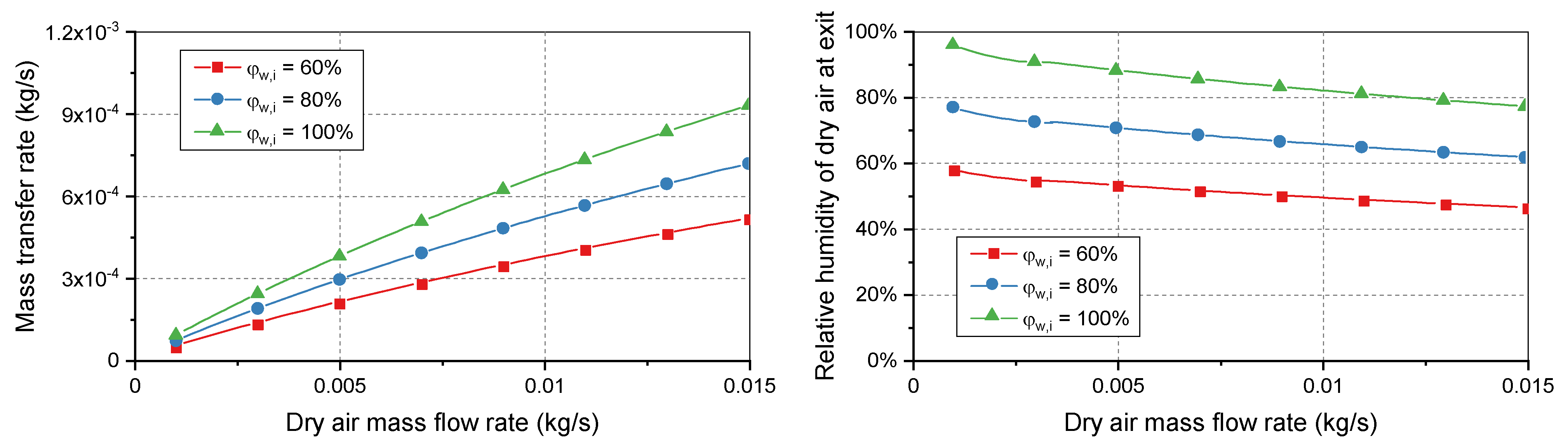
In the second simulation case, the relative humidity of the moist air at the inlet was changed to investigate the effects on the dry air.
Figure 3 shows that the performance of the humidifier was improved when the relative humidity was close to the saturated level. Both the mass transfer rate in the humidifier and relative humidity of the dry air were highest when the relative humidity of the moist air was 100%. Increasing the relative humidity of the moist air flow increased the difference in water content on the two sides of the membranes, so the higher concentration gradient drove more water particles to the dry side. Under normal conditions, the cathode of the PEMFC system often exhausts saturated air, which is useful for humidifying the supply air. However, an upsurge in demand could result in undesirable conditions: increased mass flow rates and decreased relative humidity on both sides of the humidifier. A heavy operating load can cause the humidifier to become unable to supply sufficient moisture to achieve the desired relative humidity for the supply air.
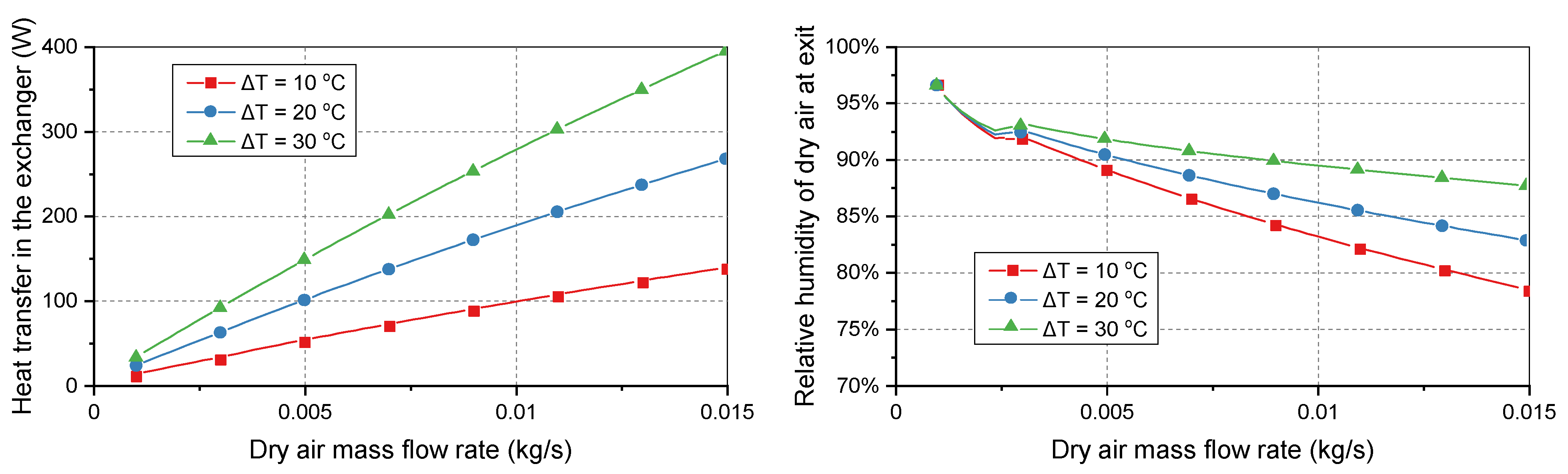
As shown in
Figure 4, the temperature difference between the two flows significantly affected the heat transfer in the exchanger and relative humidity of the supply air. Unlike the previous simulation cases where the temperature difference was kept constant, the temperature difference was varied in this case. When the temperature difference between the moist air and dry air was 30 °C, the heat transfer rate was almost three times higher than when the temperature difference was 10 °C. In addition, the relative humidity of the dry air at the outlet was increased by 13%. The mass flow rate had the opposite effect on the relative humidity compared with the temperature difference. Increasing the dry air mass flow rate decreased the relative humidity of the supply gas.
The simulation results on operating conditions of the humidifier provided the effects of mass transfer rate, relative humidity, and temperature of the flows to the heat and mass transfer. If the flow rates are constant, the supply air’s relative humidity depends more on the relative humidity of the wet side. In contrast, the mass transfer rate significantly varies with both temperature and humidity. When the changes in flow rates are considered, the wet flow has less effect on the humidifier performance than the dry side. Therefore, controlling the dry air flow rate is quicker and more effective in managing the supply air humidity.
3.2. Effects of Geometric Parameters
The developed model was used to predict the humidifier performance when the membrane dimensions change. The effects of the membrane thickness, length, and number of tubes on the heat and mass transfer rates were studied.
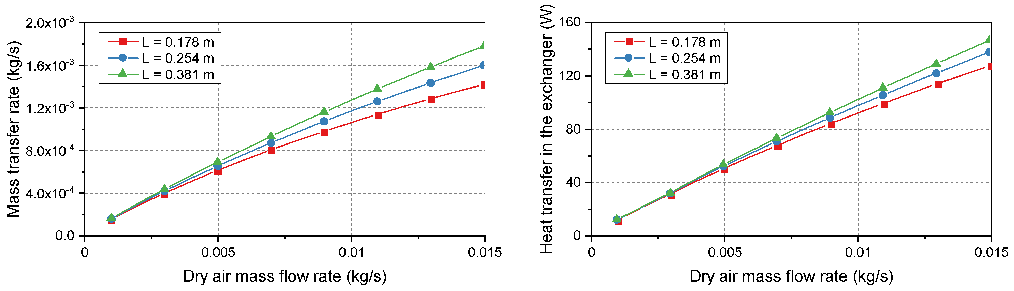
Figure 5 shows that longer membranes improved both the vapor transport and heat transfer. Three standard membrane lengths were considered for the bundle: 0.178, 0.254, and 0.381 m. At low flow rates, the heat and mass transfer rates had similar values. However, the curves deviated when the dry air flow rate was increased. At low demand, the three membrane lengths easily achieved the maximum possible heat and mass transfers between flows. Therefore, the curves coincided at the beginning of the simulation range. At heavier loads, deviations occurred because longer membranes supported a larger surface area for increased transport.
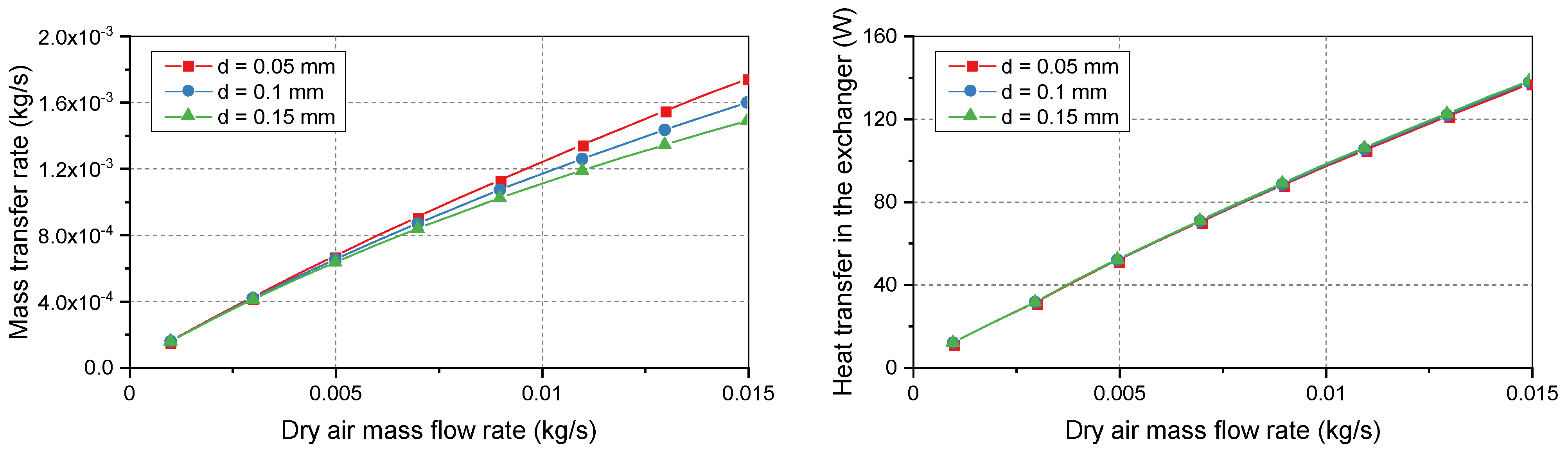
The membrane thickness is an important factor for its manufacture. The bundle requires a sufficient membrane thickness to support the structure. However, a thinner membrane allows for a higher mass transfer rate.
Figure 6 illustrates the effects of the membrane thickness on the heat and mass transfers. As the thickness increased, the mass resistance of the membranes became more significant, which prevented the movement of vapor particles between membrane surfaces. Increasing the thickness from 0.05 mm to 0.15 mm decreased the mass transfer rate by 15%. In contrast, the heat transfer rate was less affected by the membrane thickness. The membrane thickness directly affects heat conduction. However, the convective heat transfer dominates transport phenomena, which makes the heat transfer rate less dependent on the thickness.
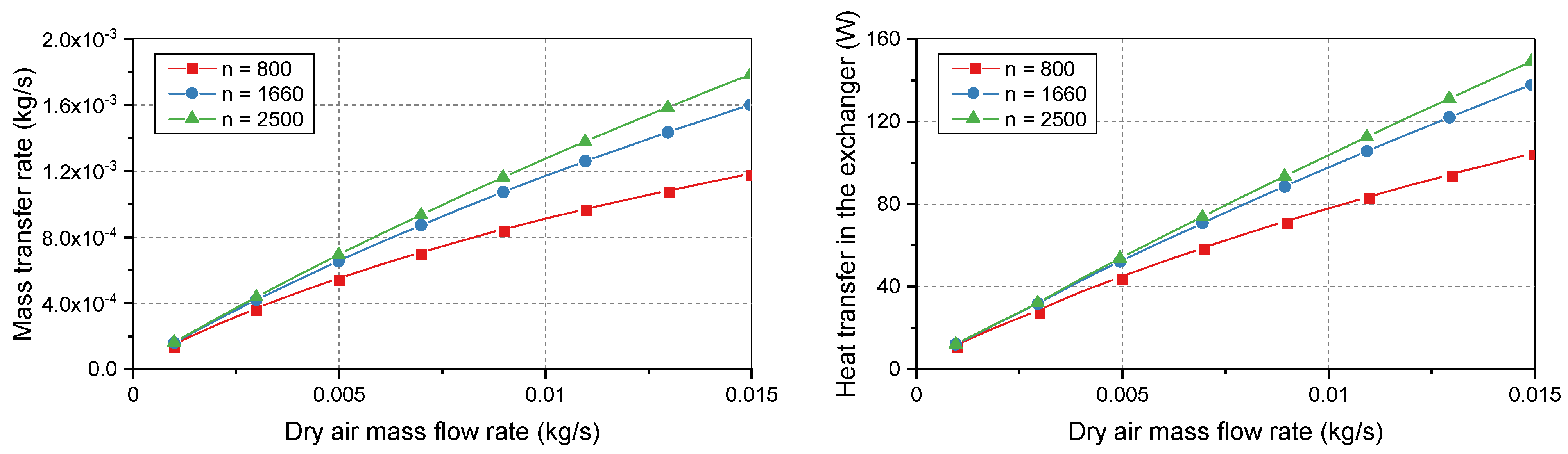
The number of membranes determines the shell diameter of the humidifier. Increasing the number of membranes can increase the operating capacity of the humidifier but increases its volume.
Figure 7 shows the humidifier performance with 800–2500 membranes. The mass transfer rate increased with more membranes. However, the effects differed between the ranges of 800–1660 membranes and 1660–2500 membranes. The higher range increased the required space, but the humidifier performance improved more slowly than in the lower range. These results can be used to optimize the sizes of the membrane bundle and humidifier.
3.3. Humidifier Performance under Transient Conditions
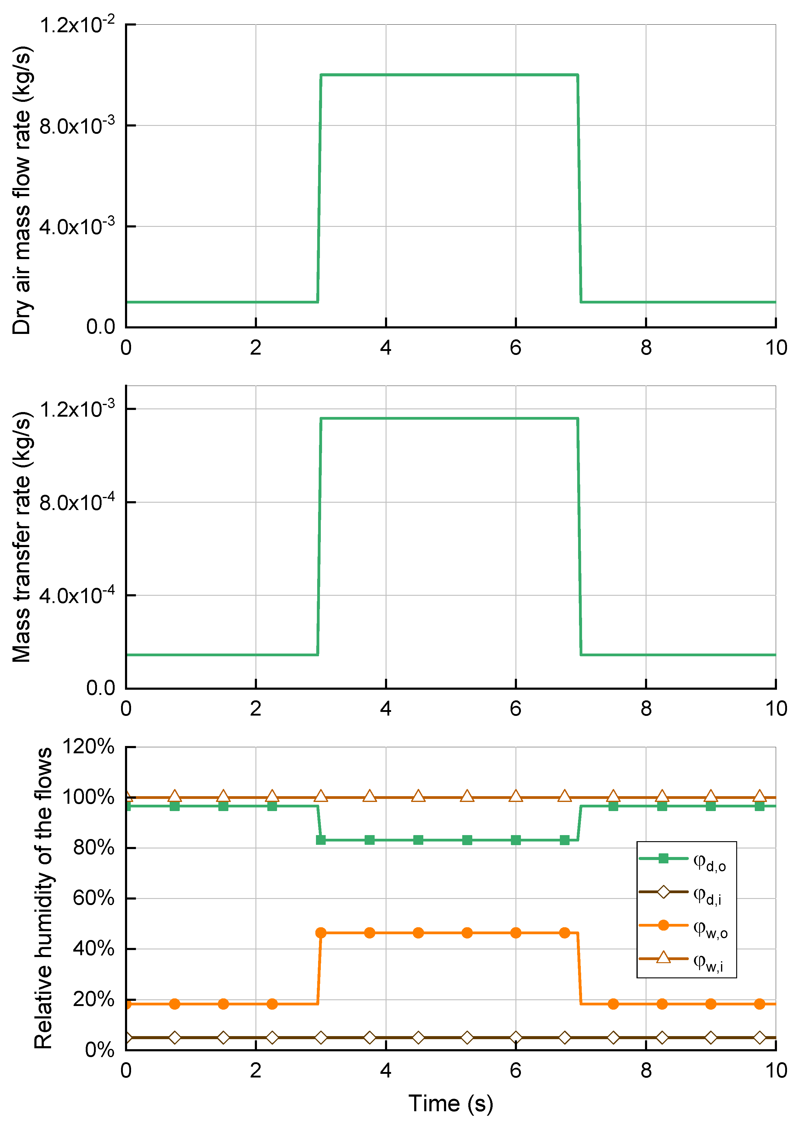
The operating conditions of the humidifier fluctuate because of the continuous changes in demand. Understanding the response of the humidifier to different conditions can help with controlling the PEFMC system. Therefore, the humidifier performance under transient conditions was investigated. The variations in load were simulated as stepwise increases or decreases in the dry air flow rate.
In
Figure 8, the flow rates were varied suddenly in intervals of 10 s. When both the dry and moist flow rates increased, the mass transfer rate increased in parallel. This is because of the higher vapor concentration on the wet side, which drove more water particles through the membranes. The relative humidity of the dry air decreased because the additional vapor was insufficient to offset the higher mass of the dry flow. Although the dry flow lacked water vapor, the relative humidity was higher on the wet side because the humidifier reached its capacity limit and could not transfer more water particles through the membranes. Therefore, the performance may suffer under high load conditions because of low moisture content. This can dry out the membranes in the fuel cell stack and cause them to degrade. Meanwhile, decreasing the mass flow rates increased the relative humidity of the supply air, which approached saturation.
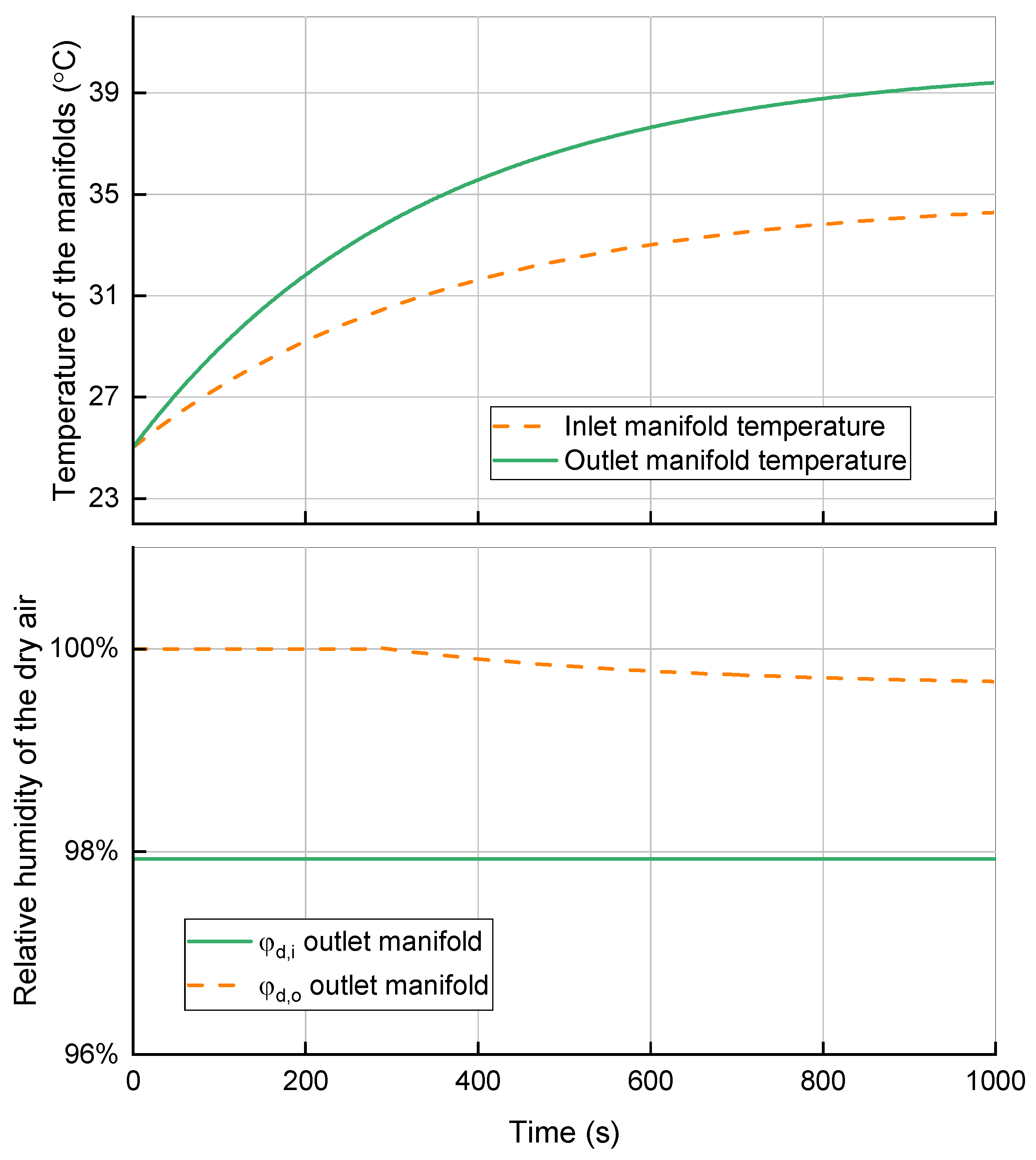
The second case simulated the long-term operation of the humidifier module, as illustrated in
Figure 9. For the first manifold at the inlet of the dry air flow, saturation could not occur because of the low moisture content. However, the second manifold sometimes experienced saturation because of the high relative humidity of the outlet air after it moved through the membrane bundle. The saturated air flow could reduce the humidifier performance because it would block the outlet channel. This situation occurred when the system operated under low load conditions for a long time. At a low flow rate, the supply air absorbed sufficient water vapor from the moist air to become nearly saturated at the inlet of the second manifold. Because the outlet of the manifold had a lower temperature than the exchanger, the dry flow approached the manifold inlet and experienced a temperature drop, which increase the relative humidity. As the operating time increased, the manifold temperature increased, which reduced the relative humidity. The increased temperatures of the manifolds were caused by heat transfer from the dry flow to the manifolds. The time for the manifolds to reach the saturated state depended on their specific heat capacity and mass and the heat transfer to the ambient air. Manifolds with higher mass and better insulation took longer to reach the steady-state condition.


