Article

Performance Evaluation of 5G Waveforms for Joint Radar Communication over 77 GHz and 24 GHz ISM Bands

1
SSA, ENSA, University of Cadi Ayyad, Marrakech 40000, Morocco
2
COSYS-LEOST, University Gustave Eiffel, F-59650 Villeneuve d’Ascq, France
*
Authors to whom correspondence should be addressed.
Energies 2022, 15(6), 2049; https://doi.org/10.3390/en15062049
Submission received: 24 January 2022 / Revised: 22 February 2022 / Accepted: 3 March 2022 / Published: 11 March 2022

Abstract

:
The V2X environment poses many challenges to emerging wireless communication systems, while it is crucial to ensure the efficiency and safety of road users. Requiring continual localization of the surroundings and accurate obstacle detection while providing high reliability in dense networks and low latency in high-mobility environment communication systems imposes a challenge to the driver-assistance field given that we are overly limited in terms of frequency bands and resources. Hence, pooling of the available frequency resources between different applications can help increase the spectral efficiency. A new collaborative approach multiplexed in the time domain, namely RadCom, which can be described as a joint radar and communication system that performs both vehicle-to-everything communication and detection of the neighboring obstacles in the vehicular environment, has been proposed to overcome the limitations of the existing conventional radar system. Based on orthogonal frequency division multiplexing (OFDM), this RadCom system proved to be suitable up to now for V2X. Moreover, a new RadCom system based on universal frequency multi-carrier (UFMC), an advanced fifth-generation (5G) waveform, has been proposed to enhance the spectral efficiency and surmount the shortcomings induced by the OFDM waveform. This recent RadCom system has been studied in the new frequency range of 76–81 GHz; precisely, 77 GHz. Hence, in this paper, we propose to compare both subsystems of the proposed RadCom system over two different frequency carriers, 24 GHz and 77 GHz, and to adopt the proper system parametrization in order to meet appropriate wireless solutions for automotive RadCom systems.

1. Introduction

The V2X environment poses many challenges to emerging wireless communication systems, while it is crucial to ensure the efficiency and safety of road users. It is for this reason that intelligent transportation systems (ITSs) [1] have been meticulously studied and standardized over the past decade. High reliability in dense networks and low latency in high-mobility environments are the main requirements of each ITS standard from LTE-V2X to ITS-G5. However, these new solutions have been unable to fulfill the necessary specifications of V2X communication as they suffer from a huge performance degradation in high-mobility environments and high-density geographical areas. With these challenges in mind, researchers and industrialists around the globe focused further on 5G as a flexible network where spectral efficiency, low latency, and reliability are new requirements to fulfill.
In addition to that, the vehicular environment requires continual localization of the surroundings and accurate obstacle detection to fully guarantee the safety of road users. This imposes another challenge to the driver-assistance field given that we are overly limited in terms of frequency bands and resources. Hence, pooling of the available frequency resources between different applications and users can help increase the spectral efficiency. The use of new 5G access techniques, waveforms, and architecture is evidently necessary in order to develop a new collaborative approach multiplexed in the time domain, namely RadCom, that can be described as a joint radar and communication system that performs both vehicle-to-everything communication and detection of the neighboring obstacles in the vehicular environment [2,3,4].
According to the authors of this survey [5], there exist many levels of integrating a joint radar-communication system. First, a full-isolation category consists of physically isolating or co-locating the radar and communication components, which results in one transmitter interfering with the other. Another approach to the integration of the RadCom system is the co-existence approach, in which the transceivers of the sub-systems consider each other as interferers. Hence, advanced mitigation techniques are needed in order to eliminate interference caused by radar-communication transceivers, which increases the overall complexity. Another approach exists based on shared knowledge; namely cooperative integration. Mainly, both the communication system and radar system send mutual information in order to improve the overall performance, especially interference mitigation. Finally, there is the co-design approach that we adopt in our research, in which the transmitters and receivers of both systems are jointly designed. This implies that the available resources are shared in either the time domain or the frequency domain (or both), which increases the spectral efficiency.
The co-design RadCom concept attracted many researchers in the early 2000s [6,7], where many field experts proposed OFDM as a multi-carrier waveform that efficiently allows the use of the available resources; hence, it satisfied the requirements of both RadCom subsystems [8]. Although the OFDM waveform offers simple and independent velocity and distance estimation, the growing nature of the vehicular environment causes performance loss due to high mobility, thereby causing inter-carrier interference (ICI). Moreover, in order to avoid inter-symbol interference (ISI), a long cyclic prefix (CP) is padded to the signal causing a significant spectrum loss [9].
However, UFMC, as a new emerging waveform, offers improved spectrum use and better localization in the frequency domain [10,11]. In fact, the use of the UFMC improves the spectral efficiency due to the suppression of the cyclic prefix used by OFDM; thus, it improves the data rate. In addition to that, the UFMC achieves low out-of-band emissions while retaining the simplicity of OFDM. In fact, the UFMC offers all these previously cited advantages only by applying a simple filter; hence, in terms of complexity, the UFMC is slightly higher than OFDM. Moreover, being a simple filtered version of the OFDM waveform adds ease of implementation to MIMO techniques if needed [12]. Therefore, UFMC is proposed as a RadCom multicarrier waveform in our paper [13], compared to OFDM RadCom, and it proved to be suitable for this application by means of simulations while offering great radar and communication performance.
The system parameters adopted in our simulations were held on the 77 GHz carrier frequency whereas other parameters can be adopted to enhance the system performance. Thus, in this paper, we investigate the OFDM-based RadCom and our proposed UFMC-based RadCom scheme under the 24 GHz ISM band with different system parameters in a vehicular environment and conduct performance comparisons of both carrier frequencies in order to meet proper requirements for the RadCom application.
The rest of the paper is organized as follows. Section 2 details the signal propagation model, the OFDM RadCom signal model, and the UFMC RadCom signal model. In 
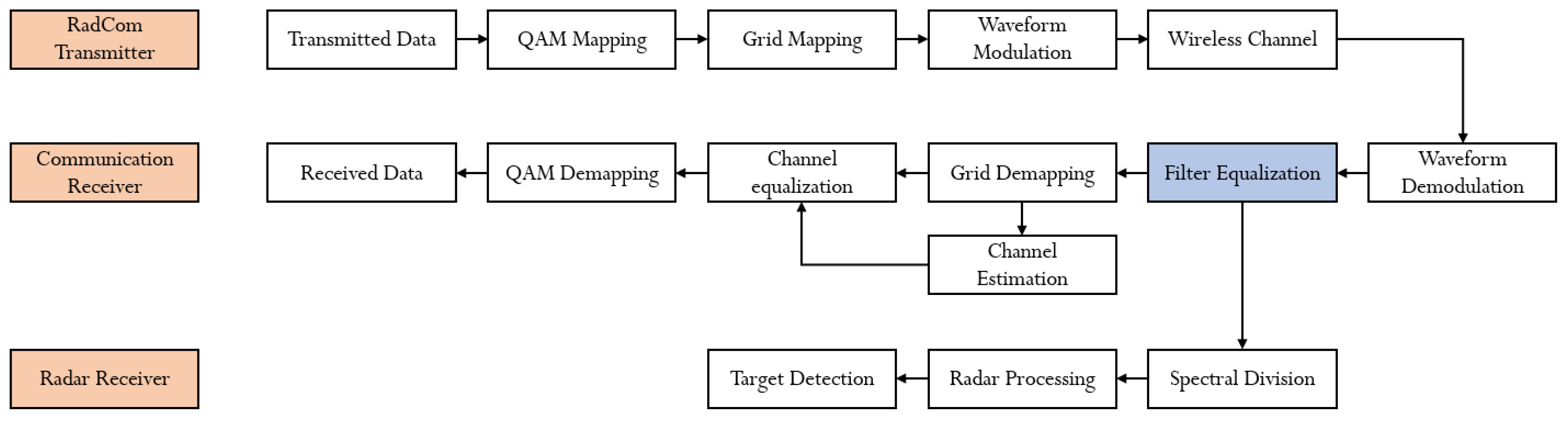
Section 3 we detail the RadCom system block diagram, more specifically the radar receiver block diagram. We dedicate Section 4 to studying the system parametrization. In Section 5, simulations and some discussions are presented for both frequency bands. Finally, the conclusions are given in Section 6.

2. Signal Propagation

As previously detailed in [13], the counterpart of the passband transmitted signal x p b ( t ) = x ( t ) e j 2 π f c t can be expressed as follows:
y p b ( t ) = j = 0 L c h 1 h j ( t ) x ( t τ j ( t ) ) e j 2 π f c ( t τ j ( t ) )
where f c is the carrier frequency, L c h denotes the number of propagation paths τ j ( t ) , and h j ( t ) is the time-varying channel gain associated to the l-th path. This model also accounts for the multi-target case.
Hence, the time-varying delay due to the varying motion between the RadCom system and the targeted vehicle is given by the following expression:
τ ( t ) = β d ( t ) c = β ( d c + v c t )
where c is the speed of light and d is the distance between the RadCom transmitter and the targeted vehicle at t = 0 . v is the relative speed at t = 0 [14]. It should be mentioned that in this case, acceleration and higher-order motion have been ignored. We introduce the parameter β to model both the communication system and the radar using the same equation. In this case:
β = 1 f o r c o m m u n i c a t i o n β = 2 f o r r a d a r
and the received signal can be written as follows:
y ( t ) = j = 0 L c h 1 h j ( t ) x ( ( 1 β v d c ) t τ j ) e j 2 π f c τ j e j 2 π f d j t
where τ j = β d 0 c is a constant delay and f d j = β f c v d c is the motion-induced frequency shift, also known as the Doppler shift (Doppler shift is a function of the carrier frequency and angle of arrival θ l of the l-th path, such that f j = f d j c o s θ j [15], f d j is the maximum shift in this case). The term s = β v d c is known as the time-scale factor [16].
Based on Equation (3), we can conclude that the received signal is a sum of attenuated, Doppler-shifted, time stretched/compressed and phase-shifted delayed copies of the transmitted signal. Phenomena of multi-path propagation considering Doppler effects can be modeled as a convolution with a filter, given as:
h ( t , τ ) = j = 0 L c h 1 h j ( t ) e j 2 π f c τ j e j 2 π f d j t δ ( ( 1 s ) t τ j )
Equation (4) is the impulse response of the channel.

2.1. OFDM RadCom Signal Model

Let x o n be the transmitted OFDM signal:
x o n = r = 0 M 1 q = 0 N c 1 a q , r e j 2 π q ( n r N o ) N c
N o = N c + N c p is the OFDM symbol length. N c p denotes the CP length needed to avoid ISIs. The received OFDM signal is a convolution between x o n and the discrete presentation of the impulse response of the channel; it can be expressed as:
y o n = r = 0 M 1 j = 0 L c h 1 q = 0 N c 1 h j a q , r e j 2 π q n N c e j 2 π q Δ f τ j e j 2 π q s j n N c e j 2 π q r N o N c e j 2 π f d j n N c Δ f + z [ n ]
where z n denotes additive Gaussian noise with variance σ z 2 . Further details are provided in [13].

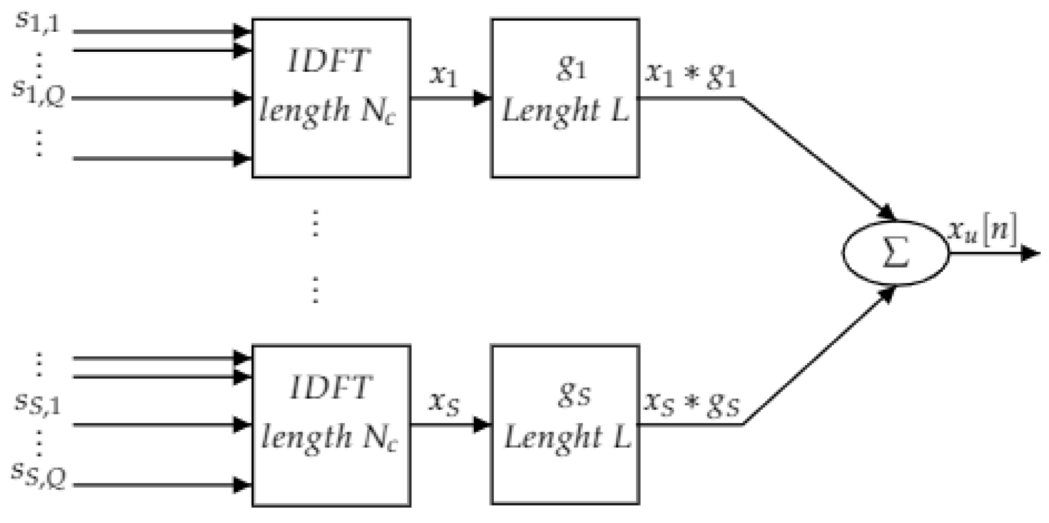
2.2. UFMC RadCom Signal Model

The UFMC discrete-time baseband signal is the superposition of the subband wise filtered subcarriers [17], therefore it can be expressed as follows:
x u n = s = 0 S 1 g s n x s n
where S is the total number of subbands of length Q subcarriers for each one. ⊗ denotes linear convolution and g s [ n ] is the filter used in the s-th subband. It is defined as in (7):
g s n = g n e j 2 π Q / 2 n N c e j 2 π ( S 0 + s Q ) n N c
with g n being the prototype filter of length L and S 0 denoting the starting frequency of the lowest subband. x s [ n ] is the sth group of subcarriers. It is an OFDM symbol shifted to the appropriate subband. It is given by (8):
x s n = r = q = 0 Q 1 s s , q , r e j 2 π q ( n r N u f m c ) N c e j 2 π ( S 0 + s Q ) ( n r N u f m c ) N c
where s s , q , r are the complex symbols transmitted on the q-th subcarrier in the s-th subband during the r-th period. They are spread over the overall signal and transformed to time domain, with an IDFT of length N c . The term e j 2 π ( S 0 + s Q ) n N c performs frequency shifting of both the data and filter coefficients to the appropriate subband. Because of the convolution, the resulting UFMC signal is of length N u f m c = N c + L 1 . The filtering operation makes it possible to suppress the OOB leakages, with the Dolph–Chebyshev filter being the most common one in the literature [17].
Replacing (7) and (8) in (6), and applying some simplifications, the transmitted UFMC signal can be written as in (9):
x u n = s = 0 S 1 r = + q = 0 Q 1 l = 0 L 1 s s , q , r g Q n l r N u f m c e j 2 π q l N c e j 2 π ( S 0 + s Q ) ( n r N u f m c ) N c
with g Q n = g n e j 2 π Q / 2 n N c being the prototype filter shifted to the subband center frequency [17]. Considering the same channel model as for OFDM, the received UFMC signal can be expressed as follows:
y u n = e j 2 π n κ N c s = 0 S 1 r = + q = 0 Q 1 j = 0 L c h 1 l = 0 L 1 s s , q , r h [ η j ] e j 2 π f d j ( n + δ ) g Q n l η j r N u f m c + δ e j 2 π q l N c e j 2 π ( S 0 + s Q ) ( n η j r N u f m c + δ ) N c
Figure 1 depicts the synthesis of a UFMC signal. In the following section, we explain how to use the two waveforms in the radar context.

3. System Model

3.1. RadCom Block Diagram

In this section, we define the block diagram of a RadCom system. The RadCom system architecture is depicted in Figure 2. The RadCom transmitter generates QAM modulated symbols. The grid-mapping block shapes the QAM symbols and pilots into a time-frequency grid in order to apply multi-carrier modulation. The signal is afterwards transmitted over the wireless channel provided in (4). The receiver side of a single user consists of the communication receiver that decodes communication signals and the radar receiver that performs obstacle detection. The common block between these two receivers is the waveform demodulation block in which we perform multi-carrier demodulation following the same waveform at the transmitter side. For the communication receiver, we address pilot-aided channel estimation; hence, pilot extraction is performed in order to apply channel estimation and equalization. Afterwards, the output symbols are QAM demodulated.
In the following, we focus on detailing the blocks composing the radar receiver. It should be mentioned that the block “Filter Equalization”, presented in blue, is used only for UFMC symbols.

3.2. Radar Receiver

The back-scattered signals contain information about the obstacles surrounding the main user. More specifically, and as demonstrated in Section 2, it is the channel applied to these echoes that contains the different distances and velocities of the obstacles. These echoes can be expressed in the frequency domain as follows:
Y = X H ^
where Y is the received signal, X is the transmitted signal, and H is the channel impulse response. Based on the known transmitted symbols, a raw channel estimation is first performed. For the OFDM signal it is expressed as:
H ^ o = X 1 Y o
The raw channel estimation for UFMC at each sub-carrier can be written as:
H ^ u = ( F s X s ) 1 Y u
where ( . ) s means the sub-carrier belonging to the s-th subband. F s is the known filter frequency response at this sub-carrier. From (10) and (11), it is clear that UFMC channel estimation differs from OFDM only by the filter response. Hence, in the system model diagram (Figure 2), we propose to add a filter equalization block to account for the filter impact on the UFMC received signal. This operation makes the UFMC signal equivalent to OFDM afterwards. Hence, in the following, we drop the ( . ) u and ( . ) o subscripts.
The extraction of the channel estimation is the output of the first block of the radar receiver. It is named Spectral Divisiondue to the fact that the channel is estimated based on an element-wise division of the received signal by the transmitted signal in the frequency domain.
The second block of the radar receiver is the one responsible for extracting the distance and velocity information from the channel equation. The estimated frequency-domain channel-transfer function at each sub-carrier for the r-th symbol can be given by:
H ^ r , q = j = 0 L c h 1 e j 2 π q Δ f τ j e j 2 π f d j r N o N c Δ f + Z r , q ,
It is worth noting that L c h , which is the number of propagation paths, is considered in this equation as the number of targets surrounding the user. As one can see from (12), the channel contains the delay induced by each target τ j and the Doppler shift f d j caused by the the motion of the targets. Hence, by simply applying first a fast Fourier transform (FFT) over the time axis and secondly an inverse fast Fourier transform (IFFT) over the frequency axis, we generate in a distance–velocity grid different peaks that correspond to different obstacles. As illustrated in Figure 3, this algorithm is based on periodogram estimation, which we use to describe the process as a 2-Dimension periodogram. In fact, the 2D periodogram estimates sinusoidal frequencies (row-wise and column-wise). These frequencies need to be translated into a distance and velocities through the following equations:
d j ^ = q j ^ c 2 N Δ f
v j ^ = r j ^ c 2 f c M T o Δ f
We have N N c and M N s y m b , where N is the FFT of length and M is the IFFT of length of the 2D periodogram, respectively. The main advantage of this approach is that the estimation of the delay as well as the Doppler shift are independent.
After the spectral division and the 2D periodogram process (filter equalization for UFMC modulation), we need to verify if the generated peaks in the 2D periodogram correspond to existing targets. The Target Detection block is responsible for identifying if the peak is produced by a true target. Mainly, two types of error can occur in the process of detection:
  • Missed target: A true target is discriminated if its main peak is considered as a side lobe for a closer target.
  • False alarm: This error happens when the side lobe of a detected target is considered as an existent target also named a ghost target.
First, we introduce the threshold ξ that helps decide between two hypotheses of the existence of noise in the signal power. Then, a statistical test is applied to the function of the received signal ζ :
ζ < H 0 H 1 ξ
where H 0 is the received signal without noise and H 1 is the received signal of the target reflection propagated through the channel plus the noise; it can be as expressed in Equation (16) as follows:
y [ n ] = z [ n ] H 0 n o i s e o n l y x [ n ] h [ n ] + z [ n ] H 1 s i g n a l p l u s n o i s e
The result of the comparison of the function of the received signal with the threshold in Equation (15) can be described by the probability density function (PDF) of the test statistic under H 0 versus the PDF under H 1 . In radar processing, power detection is adopted. Hence the threshold can be expressed as [18]:
ξ = σ z l n ( P f a )

4. Waveform Parameterization

One of the main challenges of the RadCom system is the system parametrization. In fact, the radar and communication subsystems have different requirements in which one can directly affect the performance of the other. Hence, optimal system parametrization cannot be achieved.
The Time Guard adopted by the modulation system must be restricted to some constraints. First, it needs to be larger than the time of a round trip of the furthest target and larger than the time separating the first received signal and its last path:
T c p > 2 d m a x c τ e
where d m a x corresponds to the range of the furthest object and c is the speed of light. τ e is the maximum excess delay. The first condition in Equation (18) is crucial in order to preserve orthogonality in the time domain. However, the second condition is essential for the communication subsystem of the RadCom system to avoid ISI.
The second parameter that affects both the radar and communication subsystems is the subcarrier spacing Δ f . In fact, the subcarrier spacing helps preserve the orthogonality of the system in the frequency domain, hence it needs to be greater than the maximum Doppler shift f d m a x that can be induced to the signal. This can be expressed as follows:
f d m a x Δ f
The distance resolution is determined by the bandwidth B and given by [18]:
Δ d = c 2 N c Δ f = c 2 B
As for the velocity resolution, it is determined by the time of the symbol frame T m c m :
Δ v = c 2 f c N s y m b T m c m
Hence, the maximum unambiguous distance is determined by the subcarrier spacing Δ f as follows:
d u n = c 2 Δ f
Furthermore, the maximum unambiguous velocity can be written as:
v u n = c 2 f c T m c m
Note that N s y m b T m c m is the observation time.

5. Simulation Results

In this section, we present the simulation results of the OFDM-based RadCom system as well as the UFMC-based RadCom system under 2 different parameters. It is worth noting that the key parameters of any configuration are mainly based on the symbol duration T m c m , the subcarrier spacing Δ f , and the carrier frequency f c . Hence, we chose to adopt the first system detailed in [19] in which the transmission is carried on the frequency f c = 24 GHz ISM band. The system parameters are presented in Table 1. As for the channel impulse response, it is generated based on the reflection of the target using Equation (12), where each path is considered as the reflection of one target. We calculate the delay and the Doppler shift based on the distance and the velocity that we fix for each target.
Based on the velocity resolution Δ v , we rearranged the multi-carrier grid and we set the number of symbols N s y m b to 259 symbols in order to guarantee an equal number of symbols per time slot.
For targets, we chose to simulate 6 targets in which two targets shared the same distance and very close velocities to verify the velocity resolution. Target one is at a distance d = 200 m with velocity v = 32 m/s; target two is at the same distance d = 200 m and v = 30 m/s. Moreover, we needed to investigate the distance resolution; thus, we first simulated two targets at the same velocity v = 20 m/s and with a range difference smaller than the distance resolution Δ d . We simulated two other targets at the same velocity v = 17 m/s and with a range difference slightly over the distance resolution. The last target is a non-moving target at a distance d = 320 m and was simulated in order to investigate the detection of fixed objects such as traffic lights and fire hydrants. The following Table 2 summarizes the simulated targets:
For the UFMC waveform, we used a Dolph–Chebyshev filter with an attenuation of 50 dB and the parameters adopted in this case were sub-band size Q = 64 and filter length L fixed at 16 for optimal performance.
Figure 4 illustrates the simulation results of both OFDM and UFMC RadCom systems over the carrier frequency f c = 24 GHz configuration. As depicted in the periodogram, both multicarrier waveforms support the radar application with the parameters of Table 1. Moreover, at a velocity resolution Δ v = 2 m/s, the two objects generate peaks in the periodogram; hence, they are both detectable. As for the separability of adjacent objects, target three and target four with d = 250 m and d = 252 m, respectively, respect the minimum distance of detection; hence, both objects appear on the periodogram. However, for targets five and six, the range difference is smaller than the distance resolution. This is translated on the periodogram with one peak; thus, a detected obstacle. As for the last target, it is proved that both waveforms are able to detect static objects within the detection range.
The second part of our simulation consisted of examining the OFDM RadCom and UFMC RadCom systems over the 77 GHz ISM band. In [13], the system parameters were chosen following the conditions presented in Section 4. The following Table 3 sums up the system parameters:
As can be noted, the difference between the two system parameters is significant. First, by increasing the subcarrier spacing Δ f and the number of subcarriers N c , we increase intrinsically the total bandwidth B, guaranteeing a higher throughput for the communication aspect of our RadCom system. As for the radar part, the maximum detection distance d m a x is significantly reduced in order to respect the first criterion in Section 4 while we enhance both the distance resolution and velocity resolution, Δ d and Δ v , respectively. Consequently, we reduce the range of the back-scatters in such a manner that it does not exceed the maximum distance of detection while investigating the performance of our RadCom system. Mainly, we maintain the first two targets at the same distance and different velocities to review the velocity resolution. For the last target, we test the probability of detection of static objects. Finally, we use four other objects to examine the range resolution.
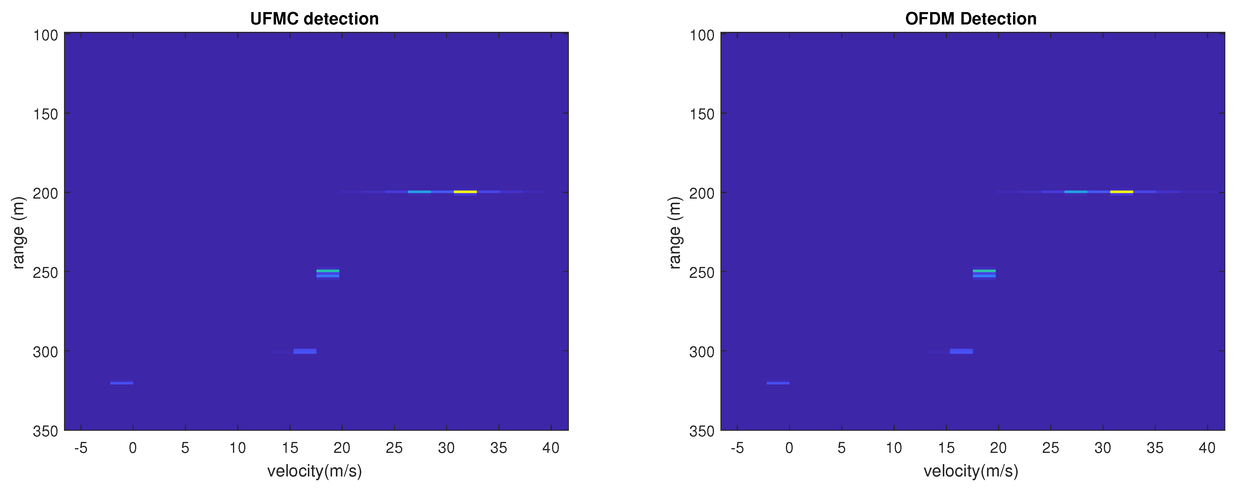
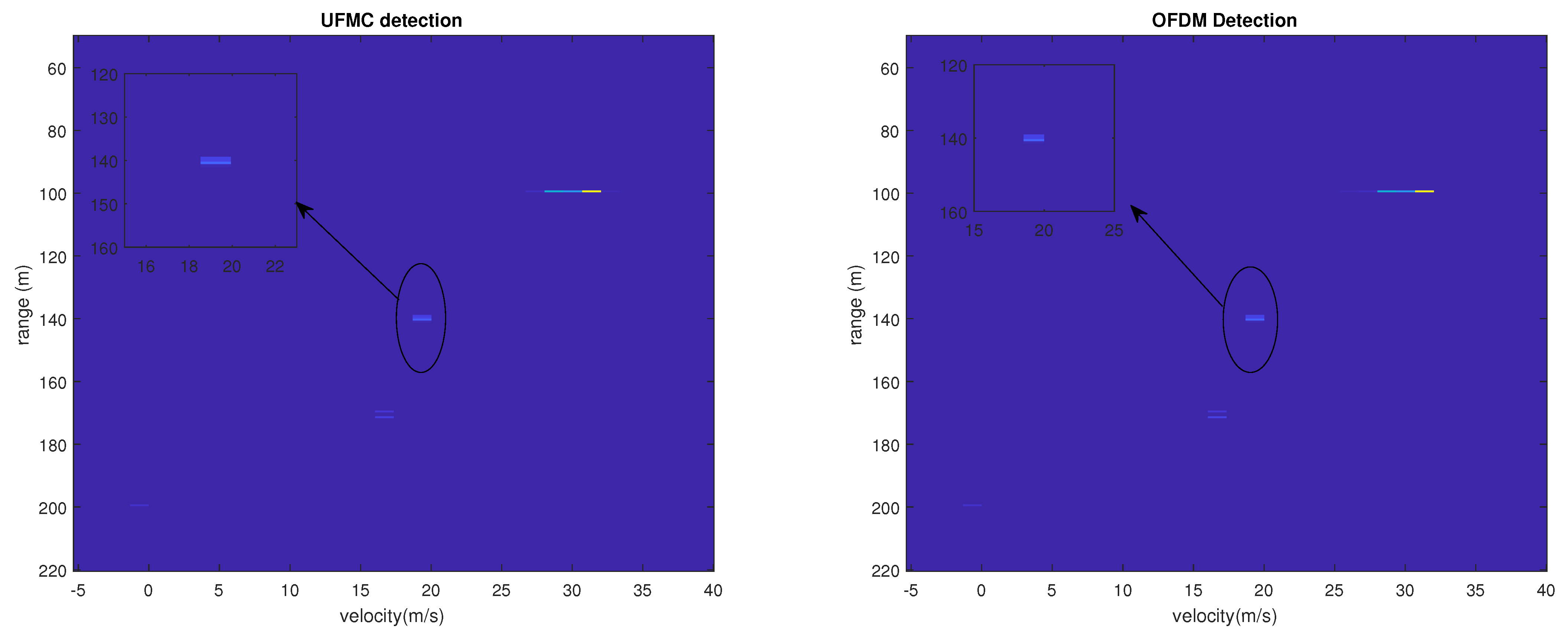
As depicted in Figure 5, all targets generate peaks in the distance–velocity grid with different amplitudes. This is due to the attenuation induced by the distance separating the obstacles and the vehicles. Consequently, the seventh target, which is at the maximum distance of detection d m a x , is barely distinguishable in the 2D-periodogram. Furthermore, with the reduced distance resolution Δ d that the 77 GHz system offers, targets three and four are both detectable as illustrated in the magnified figure for both OFDM and UFMC RadCom systems, whereas it is not possible to distinguish two adjacent objects with a separating distance of 1 m for the 24 GHz ISM band. In addition to that, the UFMC waveform increases spectral efficiency due to the omission of CP and reduces the high OOB power emission without any additional computational complexity.
Furthermore, we should keep in mind that the cost of implementation of these ISM bands differs. In fact, the 77-GHz-based system is highly costly compared to the 24 GHz frequency, while it is still under investigation. Despite the fact that 24 GHz system is less expensive, it suffers from distance–velocity resolution performance loss for far objects due to the deteriorated channel conditions. This implies that for the 77 GHz radar system, the precision of detection, hence the resolution, will not decrease since the maximum detection is at 200 m, which is less important than 1650 m for the 24 GHz radar. In addition to that, the total bandwidth B of both systems impacts directly the communication aspect of the RadCom system. A larger bandwidth increases the transmission throughput; hence, the 77 GHz ISM band offers a higher data rate. Thus, we conclude that for an application that requires precise resolution and short-range detection, we recommend the 77 GHz system. As for the 24-GHz-based system, it supports both short-range and long-range detection at the cost of poor resolution for far-off objects.

6. Conclusions

In this paper, we proposed a novel RadCom system based on a UFMC waveform over different radar systems and compared it to an OFDM RadCom system. It has been proven that this new waveform can support radar application over both 24 GHz and 77 GHz frequency bands, as well as improving the overall performance in terms of spectrum efficiency and complexity. Furthermore, it is straightforward to fix the necessary requirements of the user application as both systems offer different bandwidths; hence, user throughput and mainly different detection parameters can be beneficial for some particular environments. For instance, if the application requires far-off detection with less precision and medium-throughput transmission, we recommend the 24 GHz system. However, for high-data-rate transmission and precise distance–velocity detection, we suggest the 77 GHz system. It is worth discussing in the future the feasibility of new generalized RadCom system parameters that can be addressed to different scenarios.

Author Contributions

Conceptualization, I.K., R.E., F.E. and N.I.; methodology, I.K., R.E. and F.E.; software, I.K.; validation, R.E., F.E. and N.I.; formal analysis, R.E. and F.E.; investigation, I.K., R.E. and F.E.; resources, R.E. and F.E.; writing—original draft preparation, I.K.; writing—review and editing, I.K. and F.E.; supervision, R.E., F.E. and N.I.; project administration, R.E. and F.E.; funding acquisition, R.E. and F.E. All authors have read and agreed to the published version of the manuscript.

Funding

The present research work was supported by the European project SECREDAS funded by ECSEL.

Institutional Review Board Statement

Not applicable.

Informed Consent Statement

Not applicable.

Data Availability Statement

The data presented in this study are available on request from the corresponding author.

Conflicts of Interest

The authors declare no conflict of interest.

Abbreviations

The following abbreviations are used in this manuscript:
ITSIntelligent transport system
OFDMOrthogonal frequency division multiplexing
UFMCUniversal filtered multi-carrier
CPCyclic prefix
ICIIntercarrier interference
ISIIntersymbol interference
OOBOut-of-band
QAMQuadrature amplitude modulation
IFFTInverse fast Fourier transform
LSLeast-squares
FFTFast Fourier transform
MMSEMinimum mean squared error
ZFZero forcing
PDFProbability density function
IDFTInverse discrete Fourier transform
SNRSignal-to-noise ratio
AWGNAdditive white Gaussian noise

References

  1. Itu-r m.2057-1; Systems Characteristics of Automotive Radars Operating in the Frequency Band 76–81 GHz for Intelligent Transport Systems Applications. ITU. 2018. Available online: https://www.itu.int/en/Pages/default.aspx (accessed on 1 March 2022).
  2. Donnet, B.; Longstaff, I. Combining MIMO radar with OFDM communications. In Proceedings of the 2006 European Radar Conference, Manchester, UK, 13–15 September 2006; IEEE: Piscataway, NJ, USA, 2006; pp. 37–40. [Google Scholar]
  3. Lellouch, G.; Tran, P.; Pribic, R.; Van Genderen, P. OFDM waveforms for frequency agility and opportunities for Doppler processing in radar. In Proceedings of the 2008 IEEE Radar Conference, Rome, Italy, 26–30 May 2008; IEEE: Piscataway, NJ, USA, 2008; pp. 1–6. [Google Scholar]
  4. Haque, K.F.; Abdelgawad, A.; Yanambaka, V.P.; Yelamarthi, K. LoRa Architecture for V2X Communication: An Experimental Evaluation with Vehicles on the Move. Sensors 2020, 20, 6876. [Google Scholar] [CrossRef] [PubMed]
  5. Paul, B.; Chiriyath, A.R.; Bliss, D.W. Survey of RF Communications and Sensing Convergence Research. IEEE Access 2017, 5, 252–270. [Google Scholar] [CrossRef]
  6. Levanon, N. Multifrequency radar signals. In Proceedings of the IEEE 2000 International Radar Conference, Alexandria, VA, USA, 7–12 May 2000; pp. 683–688. [Google Scholar]
  7. Levanon, N. Multifrequency Signal Structure for Radar Systems. U.S. Patent 6,392,588, 21 May 2002. [Google Scholar]
  8. Sturm, C.; Wiesbeck, W. Waveform design and signal processing aspects for fusion of wireless communications and radar sensing. Proc. IEEE 2011, 99, 1236–1259. [Google Scholar] [CrossRef]
  9. Schaich, F.; Wild, T. Waveform contenders for 5G—OFDM vs. FBMC vs. UFMC. In Proceedings of the 2014 6th International Symposium on Communications, Control and Signal Processing (ISCCSP), Athens, Greece, 21–23 May 2014; pp. 457–460. [Google Scholar] [CrossRef]
  10. Kongara, G.; He, C.; Yang, L.; Armstrong, J. A Comparison of CP-OFDM, PCC-OFDM and UFMC for 5G Uplink Communications. IEEE Access 2019, 7, 157574–157594. [Google Scholar] [CrossRef]
  11. Khelouani, I.; Elbahhar, F.; Elassali, R.; Idboufker, N. Performance Analysis of LDS Multi Access Technique and New 5G Waveforms for V2X Communication. Electronics 2020, 9, 1094. [Google Scholar] [CrossRef]
  12. Luo, K.; Zhou, X.; Wang, B.; Huang, J.; Liu, H. Sparse Bayes Tensor and DOA Tracking Inspired Channel Estimation for V2X Millimeter Wave Massive MIMO System. Sensors 2021, 21, 4021. [Google Scholar] [CrossRef] [PubMed]
  13. Khelouani, I.; Zerhouni, K.; Elbahhar, F.; Elassali, R.; Idboufker, N. UFMC Waveform and Multiple-Access Techniques for 5G RadCom. Electronics 2021, 10, 849. [Google Scholar] [CrossRef]
  14. Napolitano, A. Cyclostationarity: Limits and generalizations. Signal Process. 2016, 120, 323–347. [Google Scholar] [CrossRef]
  15. Cho, Y.S.; Kim, J.; Yang, W.Y.; Kang, C.G. MIMO-OFDM Wireless Communications with MATLAB; John Wiley & Sons: Hoboken, NJ, USA, 2010. [Google Scholar]
  16. Napolitano, A. Generalizations of Cyclostationary Signal Processing: Spectral Analysis and Applications; John Wiley & Sons: Hoboken, NJ, USA, 2012; Volume 95. [Google Scholar]
  17. Matthe, M.; Zhang, D.; Schaich, F.; Wild, T.; Ahmed, R.; Fettweis, G. A Reduced Complexity Time-Domain Transmitter for UF-OFDM. In Proceedings of the 2016 IEEE 83rd Vehicular Technology Conference (VTC Spring), Nanjing, China, 15–18 May 2016; pp. 1–5. [Google Scholar]
  18. Braun, M. OFDM Radar Algorithms in Mobile Communication Networks. Ph.D. Dissertation, Karlsruher Institut fur Technologie (KIT), Karlsruher, Germnay, 2014. [Google Scholar]
  19. Sturm, C.; Zwick, T.; Wiesbeck, W. An OFDM System Concept for Joint Radar and Communications Operations. In Proceedings of the VTC Spring 2009—IEEE 69th Vehicular Technology Conference, Barcelona, Spain, 26–29 April 2009; pp. 1–5. [Google Scholar] [CrossRef] [Green Version]
Figure 1. Universal filtered multicarrier (UFMC) transmitter.
Energies 15 02049 g001
Figure 2. RadCom system model.
Energies 15 02049 g002
Figure 3. Two-dimensional (2D) periodogram processing [13].
Energies 15 02049 g003
Figure 4. UFMC waveform vs. OFDM waveform.
Energies 15 02049 g004
Figure 5. UFMC waveform vs. OFDM waveform.
Energies 15 02049 g005
Table 1. Simulation parameters.
ParameterSymbolValue
Carrier frequency f c 24 GHz
BandwidthB93.1 MHz
Subcarrier spacing Δ f 90.909 kHz
IDFT size N c 1024
Symbols N s y m b 259
Slots N s l o t 37
Symbols per slot N S p S 7
CP duration T c p 1.375 μs
Symbol duration T m c m 11 μs
QAM-4-QAM
Maximum range d m a x 1650 m
Range resolution Δ d 1.61 m
Velocity resolution Δ v 1.97 m/s
Probability of false alarm P f a 0.01
Signal-to-noise ratioSNR10 dB
Table 2. Simulated Targets.
Targets
Distance (m) d i [200; 200; 250; 252; 300; 301; 320]
Velocity (m/s) v i [32; 30; 20; 20; 17; 17; 0]
Table 3. Simulation parameters.
ParameterSymbolValue
Carrier frequency f c 77 GHz
BandwidthB245.8 MHz
Subcarrier spacing Δ f 120 kHz
IDFT size N c 2048
Symbols N s y m b 175
Slots N s l o t 25
Symbols per slot N S p S 7
CP duration T c p 1.334 μ s
Symbol duration T m c m 8.33 μ s
QAM-4-QAM
Maximum range d m a x 200 m
Range resolution Δ d 0.60 m
Velocity resolution Δ v 1.34 m/s
Probability of false alarm P f a 0.01
Signal-to-noise ratioSNR10 dB
Distance (m) d i [100; 100; 140; 141; 170; 172; 200]
Velocity (m/s) v i [30; 32; 20; 20; 17; 17; 0]
Publisher’s Note: MDPI stays neutral with regard to jurisdictional claims in published maps and institutional affiliations.

