
Control System for Multi-Input and Simple-Output Piezoelectric Beam Actuator Based on Macro Fiber Composite


Abstract
:1. Introduction
2. Synthesis of Control Algorithm
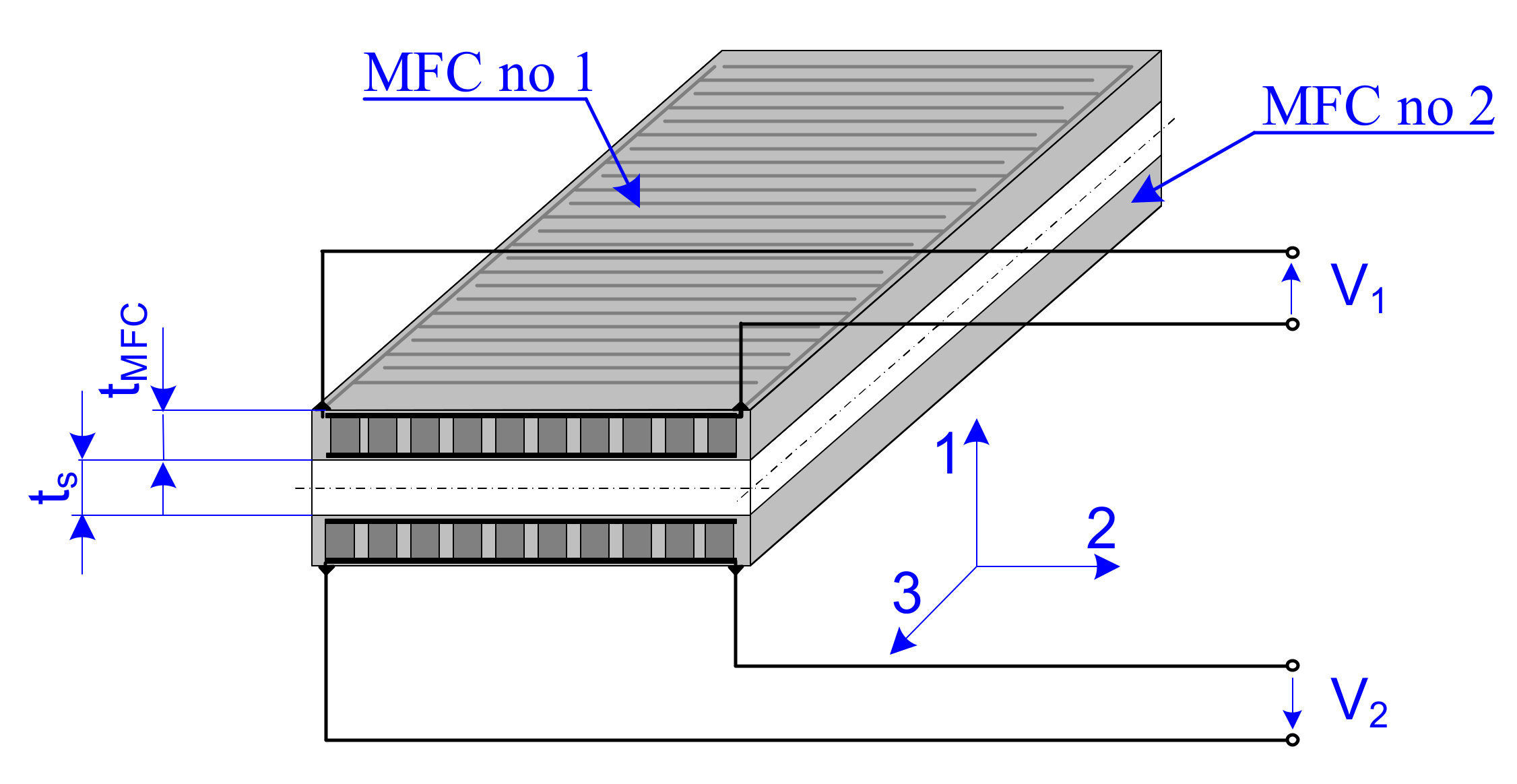
2.1. Simulation Model of a Cantilever Beam Containing Two MFC Patches
2.2. Model of Forces Generated by Two MFC Patches
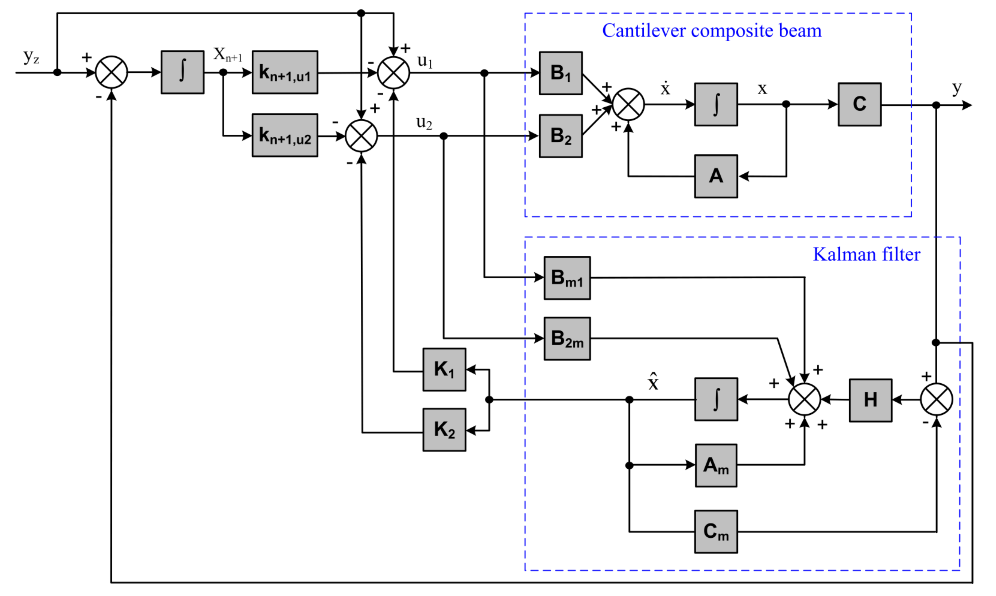
2.3. Synthesis of Control Algorithm Generating Two Control Signals
3. Research Methods
3.1. Simulation Research
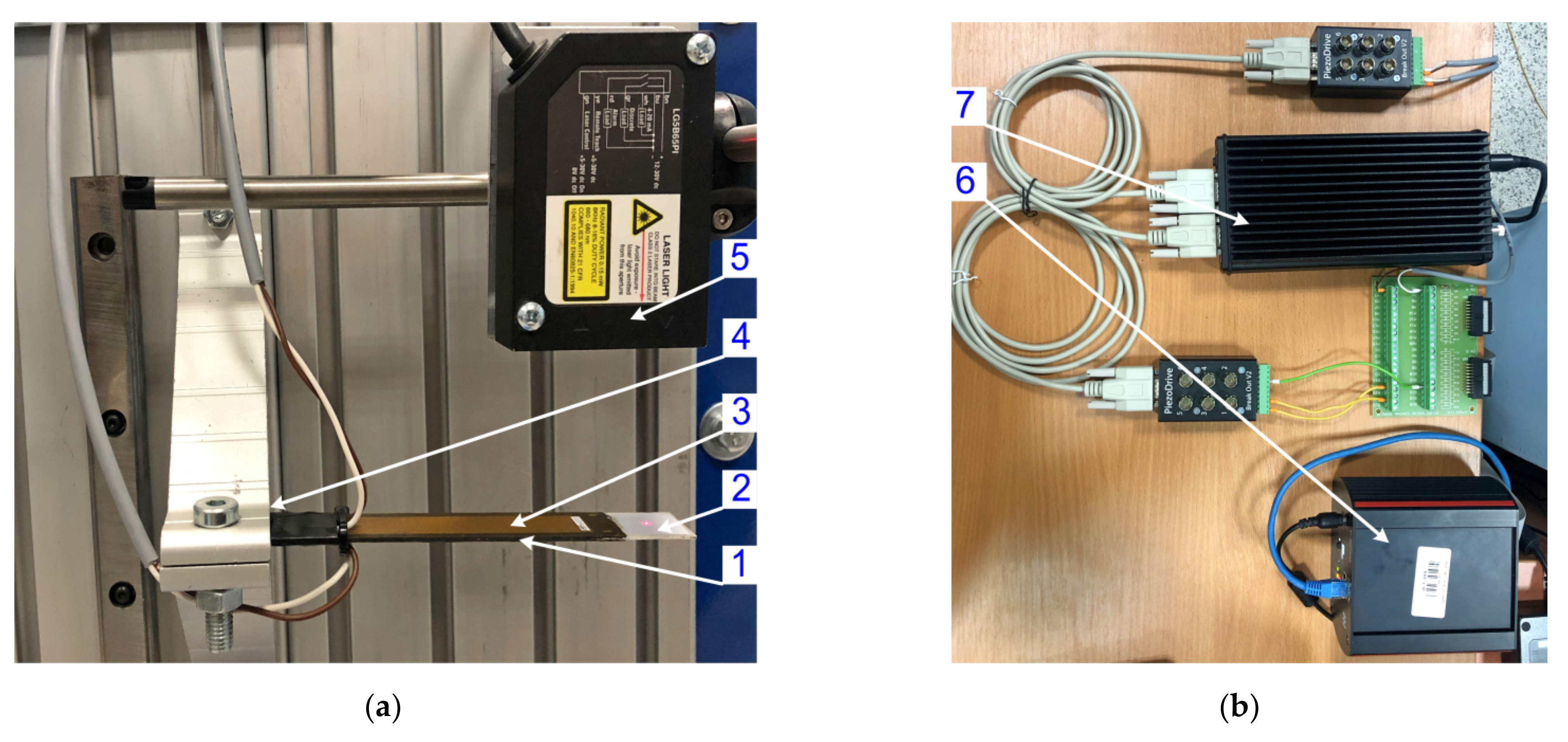
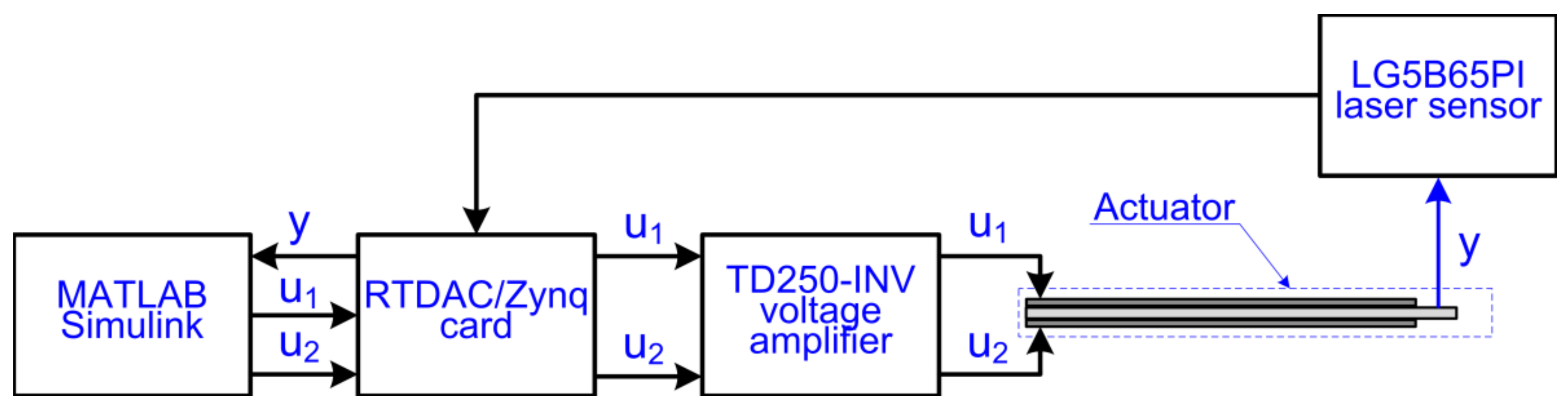
3.2. Laboratory Research
4. Results
4.1. Controllability and Observability of the Piezoelectric Beam Actuator
4.2. Weight and Covariance Matrixes
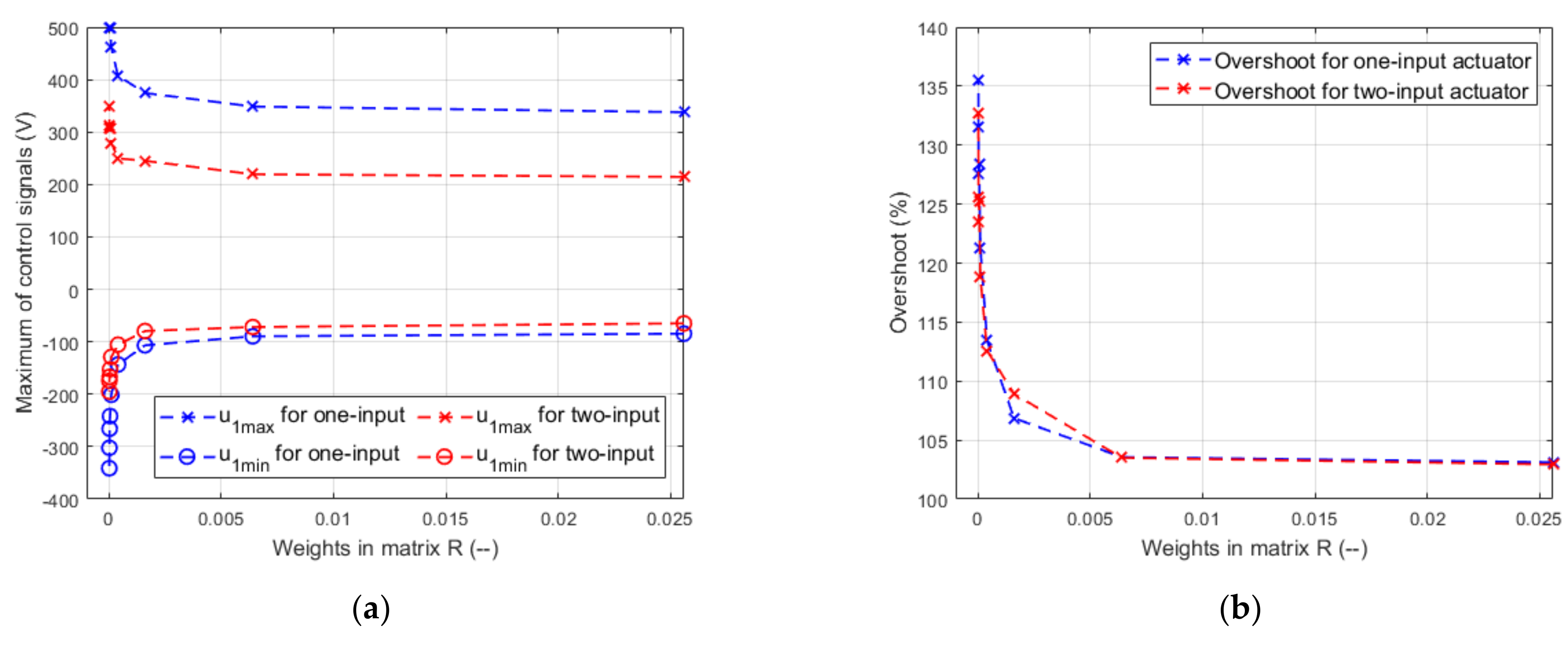
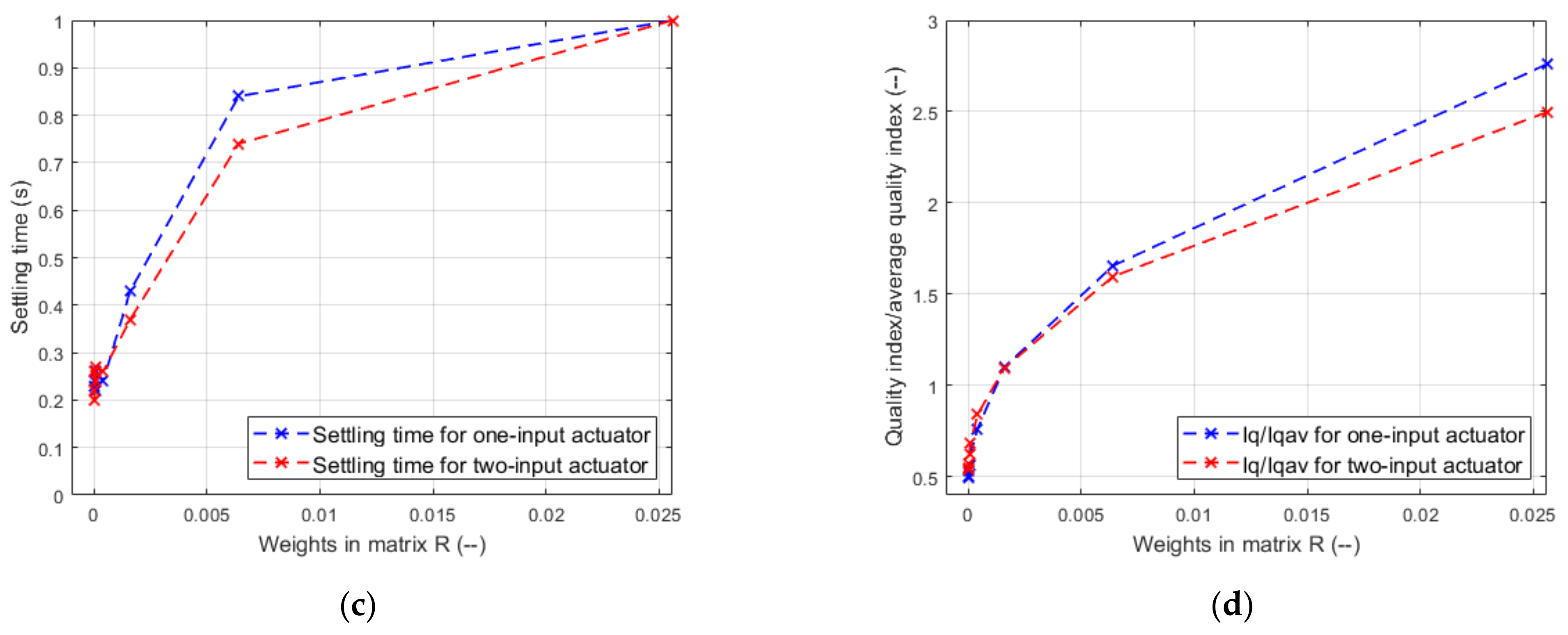
4.3. Impact of Weights in Matrix R on Control Quality in One-Input Actuator and Two-Input Actuator
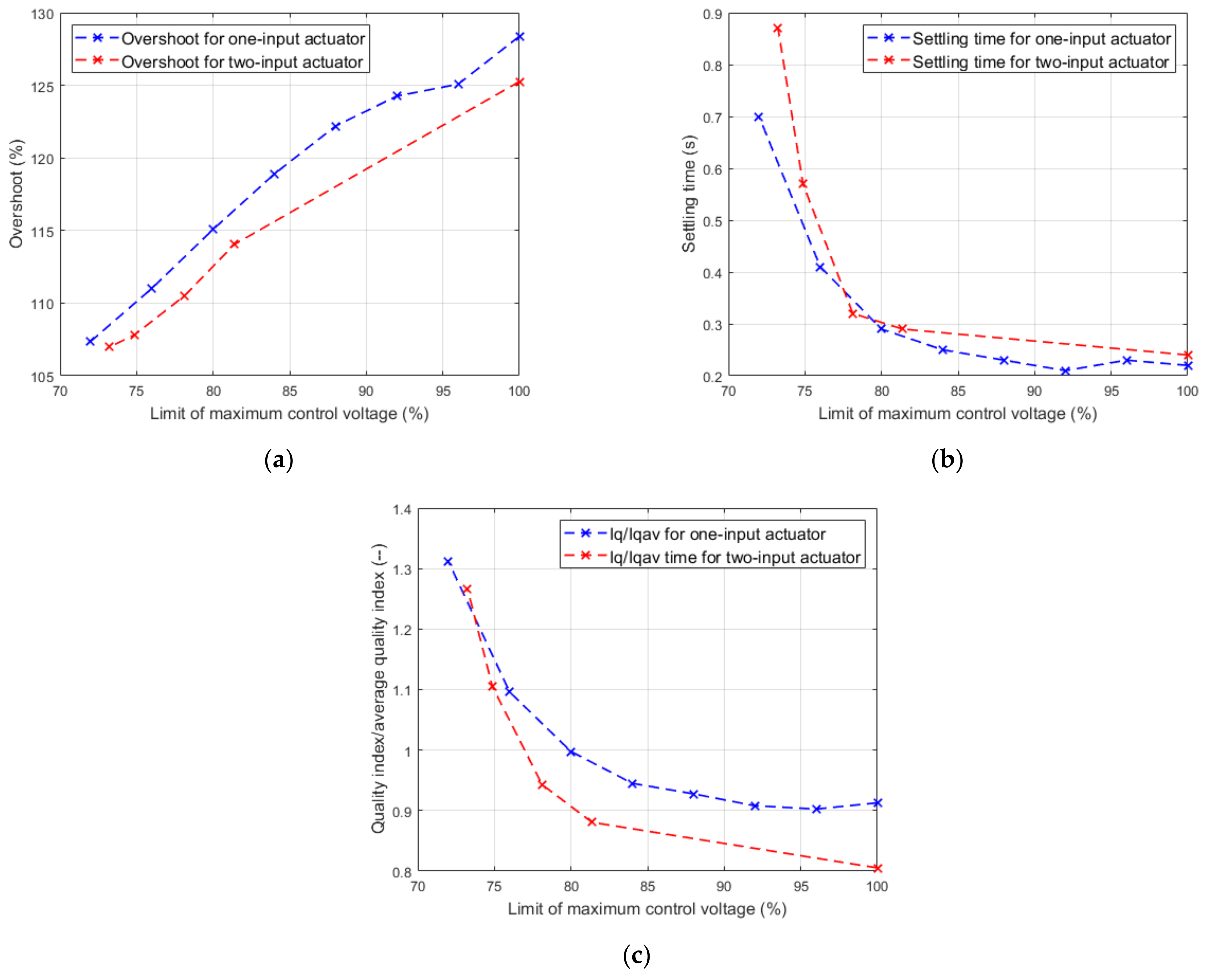
4.4. Impact of Voltage Limit on Control Quality in One-Input Actuator and Two-Input Actuator
5. Discussion
5.1. Impact of Weights in Matrix R on Control Quality in One-Input Actuator and Two-Input Actuator
5.2. Impact of Voltage Limit on Control Quality in One-Input Actuator and Two-Input Actuator
6. Conclusions
Author Contributions
Funding
Institutional Review Board Statement
Informed Consent Statement
Data Availability Statement
Conflicts of Interest
Appendix A. Schema of Control System for Two-Input Actuator
References
- Mohith, S.; Upadhya, A.R.; Karanth, N.; Kulkarni, S.M.; Rao, M. Recent trends in piezoelectric actuators for precision motion and their applications: A review. Smart Mater. Struct. 2020, 30, 013002. [Google Scholar] [CrossRef]
- DeVoe, D.L.; Pisano, A.P. Modeling and optimal design of piezoelectric cantilever microactuators. J. Microelectromechanical Syst. 1997, 6, 266–270. [Google Scholar] [CrossRef]
- Steel, M.R.; Harrison, F.; Harper, P.G. The piezoelectric bimorph: An experimental and theoretical study of its quasistatic response. J. Phys. D Appl. Phys. 1978, 11, 979. [Google Scholar] [CrossRef]
- Bailey, T.; Hubbard, J.E., Jr. Distributed piezoelectric-polymer active vibration control of a cantilever beam. J. Guid. Control. Dyn. 1985, 8, 605–611. [Google Scholar] [CrossRef]
- Azzouz, M.S.; Mei, C.; Bevan, J.S.; Ro, J.J. Finite element modeling of MFC/AFC actuators and performance of MFC. J. Intell. Mater. Syst. Struct. 2001, 12, 601–612. [Google Scholar] [CrossRef]
- Nguyen, C.H.; Kornmann, X. A comparison of dynamic piezoactuation of fiber-based actuators and conventional PZT patches. J. Intell. Mater. Syst. Struct. 2006, 17, 45–55. [Google Scholar] [CrossRef]
- Zhang, S.Q.; Li, Y.X.; Schmidt, R. Modeling and simulation of macro-fiber composite layered smart structures. Compos. Struct. 2015, 126, 89–100. [Google Scholar] [CrossRef]
- Pandey, A.; Arockiarajan, A. Actuation performance of macro-fiber composite (MFC): Modeling and experimental studies. Sens. Actuators A Phys. 2016, 248, 114–129. [Google Scholar] [CrossRef]
- Williams, R.B.; Inman, D.J.; Schultz, M.R.; Hyer, M.W.; Wilkie, W.K. Nonlinear tensile and shear behavior of macro fiber composite actuators. J. Compos. Mater. 2004, 38, 855–869. [Google Scholar] [CrossRef]
- Deraemaeker, A.; Nasser, H.; Benjeddou, A.; Preumont, A. Mixing rules for the piezoelectric properties of macro fiber composites. J. Intell. Mater. Syst. Struct. 2009, 20, 1475–1482. [Google Scholar] [CrossRef] [Green Version]
- Steiger, K.; Mokrý, P. Finite element analysis of the macro fiber composite actuator: Macroscopic elastic and piezoelectric properties and active control thereof by means of negative capacitance shunt circuit. Smart Mater. Struct. 2015, 24, 025026. [Google Scholar] [CrossRef]
- Emad, D.; Fanni, M.A.; Mohamed, A.M.; Yoshida, S. Low-Computational-Cost Technique for Modeling Macro Fiber Composite Piezoelectric Actuators Using Finite Element Method. Materials 2021, 14, 4316. [Google Scholar] [CrossRef]
- Padoin, E.; Santos, I.F.; Perondi, E.A.; Menuzzi, O.; Gonçalves, J.F. Topology optimization of piezoelectric macro-fiber composite patches on laminated plates for vibration suppression. Struct. Multidiscip. Optim. 2019, 59, 941–957. [Google Scholar] [CrossRef]
- Yang, Y.L.; Wei, Y.D.; Lou, J.Q.; Fu, L.; Tian, G.; Wu, M. Hysteresis modeling and precision trajectory control for a new MFC micromanipulator. Sens. Actuators A Phys. 2016, 247, 37–52. [Google Scholar] [CrossRef]
- Wang, X.; Zhou, W.; Zhang, Z.; Jiang, J.; Wu, Z. Theoretical and experimental investigations on modified LQ terminal control scheme of piezo-actuated compliant structures in finite time. J. Sound Vib. 2021, 491, 115762. [Google Scholar] [CrossRef]
- Xu, J.; Lou, J.; Yang, Y.; Chen, T.; Chen, H.; Cui, Y. Hysteresis modeling and feedforward compensation of a flexible structure actuated by macro fiber composites using bias bipolar Prandtl-Ishlinskii model. J. Intell. Mater. Syst. Struct. 2021, 32, 1045389X21995881. [Google Scholar] [CrossRef]
- Schröck, J.; Meurer, T.; Kugi, A. Control of a flexible beam actuated by macro-fiber composite patches: II. Hysteresis and creep compensation, experimental results. Smart Mater. Struct. 2010, 20, 015016. [Google Scholar] [CrossRef]
- Gawryluk, J.; Mitura, A.; Teter, A. Dynamic control of kinematically excited laminated, thin-walled beam using macro fibre composite actuator. Compos. Struct. 2020, 236, 111898. [Google Scholar] [CrossRef]
- Zhang, J.; Yang, Y.; Lou, J.; Wei, Y.; Fu, L. Development and hybrid position/force control of a dual-drive macro-fiber-composite microgripper. Sensors 2018, 18, 1301. [Google Scholar] [CrossRef] [Green Version]
- Yang, Y.L.; Wei, Y.D.; Lou, J.Q.; Fu, L.; Fang, S.; Chen, T.H. Dynamic modeling and adaptive vibration suppression of a high-speed macro-micro manipulator. J. Sound Vib. 2018, 422, 318–342. [Google Scholar] [CrossRef]
- Piezo Materials and Properties. Available online: https://piezo.com/pages/piezo-material (accessed on 24 December 2021).
- Bilgen, O.; Karami, M.A.; Inman, D.J.; Friswell, M.I. The actuation characterization of cantilevered unimorph beams with single crystal piezoelectric materials. Smart Mater. Struct. 2011, 20, 055024. [Google Scholar] [CrossRef]
- Smart Material—Home of the MFC. Available online: https://www.smart-material.com/MFC-product-mainV2.html (accessed on 20 August 2021).
- Yu, Y.; Zhang, X.N.; Xie, S.L. Optimal shape control of a beam using piezoelectric actuators with low control voltage. Smart Mater. Struct. 2009, 18, 095006. [Google Scholar] [CrossRef]
- Kumar, K.R.; Narayanan, S. Active vibration control of beams with optimal placement of piezoelectric sensor/actuator pairs. Smart Mater. Struct. 2008, 17, 055008. [Google Scholar] [CrossRef]
- Jain, R.K.; Majumder, S.; Ghosh, B.; Saha, S. Deflection control for piezoelectric actuator through voltage signal and it’s application in micromanipulation. Mech. Syst. Signal Processing 2015, 62, 305–323. [Google Scholar] [CrossRef]
- Kaci, A.; Giraud-Audine, C.; Giraud, F.; Amberg, M.; Lemaire-Semail, B. LQR based MIMO-PID controller for the vector control of an underdamped harmonic oscillator. Mech. Syst. Signal Processing 2019, 134, 106314. [Google Scholar] [CrossRef]
- Ebrahimi-Tirtashi, A.; Mohajerin, S.; Zakerzadeh, M.R.; Nojoomian, M.A. Vibration control of a piezoelectric cantilever smart beam by 1 adaptive control system. Syst. Sci. Control. Eng. 2021, 9, 542–555. [Google Scholar] [CrossRef]
- Wang, B.; Luo, X.; Liu, Y.; Yang, Z. Thickness-variable composite beams for vibration energy harvesting. Compos. Struct. 2020, 244, 112232. [Google Scholar] [CrossRef]
- Dosch, J.J.; Inman, D.J.; Garcia, E. A self-sensing piezoelectric actuator for collocated control. J. Intell. Mater. Syst. Struct. 1992, 3, 166–185. [Google Scholar] [CrossRef]
- Yabuno, H.; Saigusa, S.; Aoshima, N. Stabilization of the parametric resonance of a cantilever beam by bifurcation control with a piezoelectric actuator. Nonlinear Dyn. 2001, 26, 143–161. [Google Scholar] [CrossRef]
- Trindade, M.A.; Benjeddou, A.; Ohayon, R. Piezoelectric active vibration control of damped sandwich beams. J. Sound Vib. 2001, 246, 653–677. [Google Scholar] [CrossRef]
- Antoine, M.; Zheng, X.; Yu, Y. Multivariable State-Feedback Controller Design for PV Inverter Connected to a Weak Grid. Energies 2021, 14, 4441. [Google Scholar] [CrossRef]
- Hamdan, A.M.A.; Elabdalla, A.M. Geometric measures of modal controllability and observability of power system models. Electr. Power Syst. Res. 1988, 15, 147–155. [Google Scholar] [CrossRef]
- Hosea, M.E.; Shampine, L.F. Analysis and implementation of TR-BDF2. Appl. Numer. Math. 1996, 20, 21–37. [Google Scholar] [CrossRef]
- Azam, S.A.; Fragoso, A. Experimental and Numerical Simulation Study of the Vibration Properties of Thin Copper Films Bonded to FR4 Composite. Appl. Sci. 2020, 10, 5197. [Google Scholar] [CrossRef]
- Song, Z.; Su, C. Computation of Rayleigh damping coefficients for the seismic analysis of a hydro-powerhouse. Shock. Vib. 2017, 2017, 2046345. [Google Scholar] [CrossRef] [Green Version]
- Meirovitch, L. Fundamentals of Vibrations; Waveland Press: Long Grove, IL, USA, 2010. [Google Scholar]
- L-GAGE® LG Laser Gauging Sensors. Available online: https://info.bannerengineering.com/cs/groups/public/documents/literature/59786.pdf (accessed on 10 January 2022).
- RT-DAC/Zynq User’s Manual. Available online: http://www.inteco.com.pl/Docs/Rtdac_Zynq.pdf (accessed on 10 January 2022).
- TD250 V8 Six Channel ±250V Amplifier. Manual and Specifications. Available online: https://www.piezodrive.com/wp-content/uploads/2020/09/TD250-V8-R2.pdf (accessed on 10 January 2022).
- Grzybek, D. LQG Control of the Smart Truss with the Piezoelectric Active Members. In Control Engineering in Materials Processing II, Solid State Phenomena; Trans Tech Publications Ltd.: Zurich-Uetikon, Switzerland, 2014; Volume 208, pp. 125–133. [Google Scholar]
- Sibilska-Mroziewicz, A.; Ordys, A.; Możaryn, J.; Alinaghi Hosseinabadi, P.; Soltani Sharif Abadi, A.; Pota, H. LQR and Fuzzy Logic Control for the Three-Area Power System. Energies 2021, 14, 8522. [Google Scholar] [CrossRef]
- Lichota, P.; Dul, F.; Karbowski, A. System Identification and LQR Controller Design with Incomplete State Observation for Aircraft Trajectory Tracking. Energies 2020, 13, 5354. [Google Scholar] [CrossRef]
- Gapiński, D.; Koruba, Z. Control of Optoelectronic Scanning and Tracking Seeker by Means the LQR Modified Method with the Input Signal Estimated Using of the Extended Kalman Filter. Energies 2021, 14, 3109. [Google Scholar] [CrossRef]


| Parameter | Symbol | Unit | Value |
|---|---|---|---|
| Young modulus of PCB FR-4 substrate [36] | Ys | Pa | 18.6 × 10⁹ |
| Young modulus of MFC patch [23] | YMFC | Pa | 30.336 × 10⁹ |
| Young modulus of passive area of MFC patch [10] | YMFCp | Pa | 2.9 × 10⁹ |
| Density of PCB FR-4 substrate | ρs | kg/m3 | 1900 |
| Density of active area of MFC patch [15] | ρMFCa | kg/m3 | 5400 |
| Density of passive area of MFC patch [11] | ρMFCp | kg/m3 | 1420 |
| Elastic compliance of MFC patch [11] | sE33 | m2/N | 18.8 × 10⁻¹² |
| Piezoelectric charge constant of MFC patch [10] | d33 | C/N | 436 × 10−12 |
| Thickness of piezoelectric fibers in MFC patch [7] | tp | mm | 0.18 |
| Distance between electrodes in MFC patch [7] | tde | mm | 0.5 |
| Parameters | Symbol | Value |
|---|---|---|
| Distance between fixing and MFC active area | lb1 | 7.5 |
| Length of MFC active area | lb2 | 85 |
| Distance between MFC active area and end of MFC patch | lb3 | 7.5 |
| Distance between end of MFC patch and measurement point | lb4 | 10 |
| Width of beam | wb | 20 |
| Width of MFC patch | wMFC | 20 |
| Width of active area in MFC patch | wact | 14 |
| Thickness of PCB FR-4 substrate | ts | 1 |
| Thickness of MFC patch | tMFC | 0.3 |
| Exper. No. | Assumed umax (V) | ymax (mm) | tr (s) | u1max/u1min (V) | u2max/u2min (V) | ||||
|---|---|---|---|---|---|---|---|---|---|
| One-Input | Two-Input | One-Input | Two-Input | One-Input | Two-Input | One-Input | Two-Input | ||
| 1 | 6.25 | 0.516 | 0.515 | >1 | >1 | 337.8/−84.5 | 214.5/−64.8 | X | 64.88/−214.5 |
| 2 | 12.5 | 0.518 | 0.518 | 0.84 | 0.74 | 348.6/−89.5 | 219.4/−71.8 | X | 71.83/−219.5 |
| 3 | 25 | 0.534 | 0.545 | 0.43 | 0.37 | 374.4/−106.7 | 245.1/−79.4 | X | 79.66/−244.9 |
| 4 | 50 | 0.567 | 0.563 | 0.24 | 0.26 | 407.4/−143.3 | 249.7/−105.5 | X | 105.1/−249.7 |
| 5 | 100 | 0.607 | 0.594 | 0.26 | 0.27 | 460.8/−201.1 | 279.3/−128.9 | X | 128.6/−279.4 |
| 6 | 150 | 0.642 | 0.626 | 0.22 | 0.24 | 500.0/−241.7 | 307.2/−152.4 | X | 152.4/−307.2 |
| 7 | 200 | 0.638 | 0.618 | 0.20 | 0.22 | 500.0/−265.9 | 306.4/−166.9 | X | 166.9/−306.3 |
| 8 | 250 | 0.658 | 0.628 | 0.24 | 0.20 | 500.0/−302.2 | 311.7/−174.5 | X | 174.5/−311.7 |
| 9 | 300 | 0.678 | 0.663 | 0.23 | 0.26 | 500.0/−341.1 | 348.9/−195.1 | X | 195.1/−348.6 |
| Experiment No (--) | 1 | 2 | 3 | 4 | 5 | 6 | 7 | 8 | 9 |
|---|---|---|---|---|---|---|---|---|---|
| Voltage limit (V) | 480 | 460 | 440 | 420 | 400 | 380 | 360 | 350 | 340 |
| ymax (mm) | 0.625 | 0.621 | 0.611 | 0.595 | 0.575 | 0.555 | 0.537 | 0.527 | 0.499 |
| tr (s) | 0.23 | 0.21 | 0.23 | 0.25 | 0.29 | 0.41 | 0.70 | >1 | >1 |
| Experiment No (--) | 1 | 2 | 3 | 4 | 5 |
|---|---|---|---|---|---|
| Voltage limit (V) | 250 | 240 | 230 | 225 | 220 |
| ymax (mm) | 0.570 | 0.553 | 0.539 | 0.535 | 0.523 |
| tr (s) | 0.29 | 0.32 | 0.57 | 0.87 | >2 |
| Experiment No (--) | 1 | 2 | 3 | 4 | 5 | 6 | 7 | 8 | 9 | |
|---|---|---|---|---|---|---|---|---|---|---|
| Assumed umax (V) | 6.25 | 12.5 | 25 | 50 | 100 | 150 | 200 | 250 | 300 | |
| Weights: r11 and r22 (--) | 0.0256 | 0.0064 | 0.0016 | 0.0004 | 0.0001 | 44 × 10−5 | 25 × 10−5 | 16 × 10−5 | 11 × 10−5 | |
| Overshoot (%) | One-input | 103.12 | 103.56 | 106.86 | 113.42 | 121.32 | 128.38 | 127.60 | 131.52 | 135.50 |
| Two-input | 102.94 | 103,50 | 108.92 | 112.58 | 118.80 | 125.26 | 123.50 | 125.58 | 132.66 | |
| Quality index Iq (--) | One-input | 0.11300 | 0.06777 | 0.04509 | 0.03120 | 0.02567 | 0.02294 | 0.02195 | 0.02065 | 0.02018 |
| Two-input | 0.08750 | 0.05595 | 0.03843 | 0.02946 | 0.02397 | 0.02192 | 0.02002 | 0.01884 | 0.01926 | |
| Decrease of maximum control voltagefor two-input (%) | −36.50 | −37.06 | −34.54 | −38.71 | −39.39 | −38.56 | −38.72 | −37.66 | −30.22 | |
| Decrease of minimum control voltage for two-input (%) | −23.22 | −19.82 | −25.51 | −26.38 | −35.90 | −36.95 | −37.23 | −42.26 | −42.80 | |
| Experiment No. (--) | 1 | 2 | 3 | 4 | 5 | 6 | 7 | 8 | 9 |
| Limit (V) | 480 | 460 | 440 | 420 | 400 | 380 | 360 | 350 | 340 |
| Overshoot (%) | 125.08 | 124.26 | 122.2 | 118.9 | 115.08 | 111.02 | 107.36 | x | x |
| Quality index Iq (--) | 0.02268 | 0.02282 | 0.02331 | 0.02375 | 0.02507 | 0.02754 | 0.03296 | x | x |
| Experiment No. (--) | 1 | 2 | 3 | 4 | 5 |
| Limit (V) | 250 | 240 | 230 | 225 | 220 |
| Overshoot (%) | 114.04 | 110.5 | 107.82 | 106.98 | x |
| Quality index Iq (--) | 0.02397 | 0.02566 | 0.03008 | 0.03448 | x |
Publisher’s Note: MDPI stays neutral with regard to jurisdictional claims in published maps and institutional affiliations. |
© 2022 by the author. Licensee MDPI, Basel, Switzerland. This article is an open access article distributed under the terms and conditions of the Creative Commons Attribution (CC BY) license (https://creativecommons.org/licenses/by/4.0/).
Share and Cite
Grzybek, D. Control System for Multi-Input and Simple-Output Piezoelectric Beam Actuator Based on Macro Fiber Composite. Energies 2022, 15, 2042. https://doi.org/10.3390/en15062042
Grzybek D. Control System for Multi-Input and Simple-Output Piezoelectric Beam Actuator Based on Macro Fiber Composite. Energies. 2022; 15(6):2042. https://doi.org/10.3390/en15062042
Chicago/Turabian StyleGrzybek, Dariusz. 2022. "Control System for Multi-Input and Simple-Output Piezoelectric Beam Actuator Based on Macro Fiber Composite" Energies 15, no. 6: 2042. https://doi.org/10.3390/en15062042
APA StyleGrzybek, D. (2022). Control System for Multi-Input and Simple-Output Piezoelectric Beam Actuator Based on Macro Fiber Composite. Energies, 15(6), 2042. https://doi.org/10.3390/en15062042