Review

Isothermal Performance of Heat Pipes: A Review

1
MOE Key Laboratory of Enhanced Heat Transfer and Energy Conservation, Beijing Key Laboratory of Heat Transfer and Energy Conversion, College of Energy and Power Engineering, Beijing University of Technology, Beijing 100124, China
2
National Institute of Metrology, Beijing 100013, China
*
Author to whom correspondence should be addressed.
Energies 2022, 15(6), 1992; https://doi.org/10.3390/en15061992
Submission received: 9 February 2022 / Revised: 25 February 2022 / Accepted: 3 March 2022 / Published: 9 March 2022

Abstract

:
Heat pipes transfer heat via phase transformation of the working fluid, where the working fluid will keep the temperature constant and absorb or release a large amount of latent heat during phase transformation. With the development of heat pipe technology, the isothermal performance of heat pipes has been gradually emphasized in many application fields. Most studies focused on the average temperature characteristics of one heat pipe or several heat pipes with the same type, and lacked a comprehensive analysis on the isothermal performance of different heat pipes. In this paper, previous studies on the application fields of the isothermal performance of heat pipes, the isothermal level of heat pipes used in different fields, and the methods to improve the isothermal performance of heat pipes are summarized. The parameters of the wick have little effect on the temperature uniformity of the heat pipe, while the arrangement of the wick has more influence on the uniformity of the heat pipe. The most suitable charge rate is 15% to 30% of the total inner volume, and the best start-up performance and isothermal performance is at approximately 45°.

1. Introduction

The working fluid of heat pipes maintains a constant temperature during the phase change and absorbs or releases a substantial amount of latent heat. Therefore, the thermal conductivity of heat pipes is much better than that of thermally conductive materials, such as silver or copper, so heat pipes are also called superconductors. Due to their simple operation principle, heat pipes can be made into various shapes and sizes, and the working temperature range of different heat pipes varies greatly. According to the method of working fluid reflux, heat pipes can be divided into thermosyphons, capillary heat pipes, rotating heat pipes, etc. Heat pipe technology has been widely used because of its reliability, simple structure and strong heat transfer ability [1]. Gaugler explained the working cycle process and principle of heat pipes and applied for a US patent [2]. Cotter first conducted a systematic theoretical study, expounding in detail the working fluid states of heat pipes from start-up to stable operation [3]. Heat pipes have been widely used in many fields with the development of heat pipe technology. Heat pipes have also gradually received attention in their isothermal performance in the fields of solar energy utilization systems [4,5,6], isothermal reactors and furnaces [7], metrology fields [8,9,10], etc.
Due to the liquid/vapor phase transition, heat pipes also have a very good isothermal performance. The vapor working fluid is driven by a very small pressure difference. After condensation, the liquid working fluid is driven back by gravity, capillary force, or other forces. Therefore, the working fluid-wall thermal resistance mainly affects the equivalent thermal resistance of the heat pipe, and heat pipes can have very high isothermal performance. For thermal protection and thermal management applications, heat pipes can prevent local overheating. For isothermal reactors, metering and other applications need high level temperature uniform field, heat pipes can provide a uniform temperature field.
According to the shape of heat pipe, the common types of heat pipes are cylindrical heat pipe, flat heat pipe, loop heat pipe, pulsating heat pipe, and annular heat pipe. In isothermal applications, the difference between different types of heat pipes is that the isothermal region. Table 1 shows the isothermal region of common types of heat pipe in isothermal applications.
Although heat pipes have a high heat transfer performance, heat transfer limits will appear under certain conditions [11,12]. These heat transfer limits will limit the maximum heat flow in the axial direction and negatively affect stability, safety and isothermal property. When the heat pipe is running at a low temperature, the influence of the vapor viscous force is greater than the influence of the inertial force due to the low vapor pressure and density. The maximum axial heat transfer is then determined by the viscous force, which is the viscosity limit that appears [13]. Due to heating, the vapor flow rate will continue to increase. When the flow rate reaches the speed of sound, the circulation speed of the working fluid cannot be increased, which means that the heat pipe reaches the sonic limit [14]. In the working stage, the entrainment limit will appear because the vapor velocity is high and the pressure is low. Some liquid droplets may be brought back to the condenser section by vapor flow. As a result, part of the working fluid cannot be recycled, and the vapor pressure is lost [15]. In a capillary heat pipe, the returning liquid working fluid flows back to the evaporation section under the action of the capillary force of the wick; when the capillary pressure cannot overcome the pressure loss of the vapor and liquid, the capillary limit will appear, and the evaporator section will dry up [13].
In order to have high isothermal performance, the heat pipe must be fully started and a complete working fluid flow cycle must be established. The temperature variation of high-temperature heat pipes during the start-up process is very different from that of medium- and low-temperature heat pipes. Due to the low density and vapor pressure, the influence of compressibility must be considered during the start-up stage. Only when the working fluid temperature reaches the transition temperature, the high-temperature heat pipe has high isothermal property. In high-temperature applications, such as solar receiver systems operating at temperatures of 750 K and above, due to the high boiling point, latent heat of vaporization, surface tension coefficient and thermal conductivity of liquid metals, the commonly used fluids are liquid metals, such as sodium, potassium and lithium. The sound speed limit and viscosity limit should be considered during the start-up phase of liquid metal heat pipes. Only by establishing a continuous flow can the effective heat transfer and isothermal performance be improved. When the mean free path of the working fluid is very small, compared with the characteristic length of the vapor flow path defined by the Kundsen number, a continuous flow zone can be established [16]. Cao et al. [17] and Jang [18] gave two types of vapor flow zone transition temperature equations. During the flow pattern transition, the temperature rises sharply, and the temperature in the continuous flow zone is much higher than that in the free molecular flow zone. Therefore, the heat pipe is divided into a hot zone and a cold zone along the heat pipe, which can be observed at the beginning of the start-up process [1,19]. Considering the compressibility of the vapor, numerical studies have obtained the same phenomenon [20,21,22,23,24]. Therefore, a simple one-dimensional start-up model named the “flat-front” start-up model was proposed [17].
Due to the wide use of heat pipes, many studies have summarized the applications of heat pipes in different fields [25,26,27]. A lot of literatures have studied the effects of wick, heat pipe structure, working medium filling volume and inclination on the isothermal performance of heat pipe. Figure 1 shows the working process and influencing factors of the isothermal performance of heat pipes. Adding nanofluids can improve the thermal conductivity of working fluid and increase the nucleation site, which can reduce the equivalent thermal resistance of heat pipe and improve thermal performance [28,29,30,31,32]. However, it has little effect on the temperature uniformity of heat pipe, the maximum temperature gradient was reduced by about 10% [28,29,30,31,32].
Generally, the literatures only focused on the average temperature characteristics of one heat pipe or several heat pipes with the same type, and lacked a comprehensive analysis on the isothermal performance of different heat pipes. Different influencing factors need to be compared and analyzed for different sizes and types of heat pipes to obtain a more general influence law on the isothermal performance of heat pipes. In this study, the isothermal level of heat pipes in different application fields and the effect of the heat pipe structure, working fluid charge ratio, and inclination angle on the isothermal performance of heat pipes were summarized. Different types of heat pipes have different advantages in terms of maximum heat transfer, manufacturing difficulty and cost. For a unified comparison, the maximum temperature gradient is used, that is, the maximum temperature difference between the two measuring points divided by the distance. In this paper, the maximum temperature gradient of isothermal zone of heat pipes is compared. For different heat pipes, the isothermal zone can be the condenser section, whole heat pipe and other part of heat pipe.

2. Application Fields of the Isothermal Performance of Heat Pipes

2.1. Thermal Protection Applications

The isothermal performance of heat pipes is related to the fatigue reduction of mechanically formed parts due to the strong temperature gradients. In aeronautical applications, aerodynamic conditions can cause large temperature gradients, where the temperature difference can be as high as 2000 K. To enable the leading edge to withstand the mechanical stress generated by the temperature gradients, high-temperature resistant materials are used. Due to the high heat transfer performance, heat pipes can also be considered in this field. The improved heat transfer and thermal efficiency shape of this heat pipe are particularly suitable for the leading edge. Different types of heat pipes have been studied, such as rectangular [33] and D-shaped pipes [34]. Another way is to use the capillary heat pipe as the entire leading edge. Reinforcements are needed in the vapor zone, such as a cross-shaped structural member wrapped with a porous wick or simple ribs.
Camarda et al. [35] studied liquid metal heat pipes for the thermal protection of hypersonic aircraft. The heat pipe was made into an elbow form for thermal protection of the front edge and nose cover. When the heat flux density was 412 W/cm2, a hot spot was found. When the wall temperature was 1320 °C and the heat exchange was 3.27 kW, the stagnation zone temperature of the hypersonic vehicle could be reduced from 1926 W to 982 W. Xiao et al. [34] proposed a three-dimensional heat transfer numerical method and studied the heat transfer performance and temperature distribution of the heat pipe in a heat protection structure. Heat pipe cooling could significantly improve the thermal protection performance. The stagnation temperature dropped from 2414 K to 1947 K at approximately 467 K, and the rear surface temperature increased from 1453 K to 1548 K at approximately 95 K. Li et al. [36] studied a gas turbine stator cycle thermosyphon cooling system using sodium potassium alloy heat pipes. The system worked stably at 1230 °C, the heat pipe reduced the wall temperature of the stationary blade by an average of 340 °C, and the passive cooling method greatly reduced the amount of induced air. Dillig et al. [37] conducted a numerical study on the thermal management of high-temperature fuel cell systems using flat sodium heat pipes. After imbedding the heat pipes, the temperature gradient in the chimney was greatly improved, and the heat could be directly discharged from the chimney. Due to the rapid heat absorption, the temperature dropped sharply by approximately 30 K, and the temperature gradient of the active cell area dropped to approximately 10 K.
Table 2 shows the isothermal performance characteristics of heat pipes in thermal protection applications. Due to the strong heat transfer capacity of the heat pipe, the heat can be quickly transferred from the evaporator side to the condenser side, and local overheating can be effectively prevented. Therefore, in the field of thermal protection, capillary heat pipes are usually used and they can effectively reduce the maximum temperature gradient. In this application, for smaller lengths the temperature gradient decreases on average by approximately 2.8 K/mm. However, due to the constraints of heat pipes it is difficult to design very general systems, thus the development of heat pipes in this field is currently limited.

2.2. Isothermal Reactors Applications

Homogenizing the temperature in the storage or reaction vessel can improve the efficiency and quality of the product [41]. For example, in warehouses the temperature of the lower layer is 10 K higher than that of the top layer. During the heat treatment or recycling process, the reduction of the temperature gradient also improves the performance of the heat storage tank [42]. In reactors, a uniform temperature can improve the catalytic and reaction performance. Generally, the reactor system uses external heat on the reaction tube, so this process may cause catalytic failure or mechanical failure of the pipeline due to overheating. A high temperature gradient can significantly slow the reaction. The use of heat pipes can also reduce the size and quality of the reactor [7].
The annular heat pipe is usually a closed container composed of two coaxial tubes with different diameters. Generally, the annular section of a heat pipe is divided into several steam channels and separated by wicks to ensure that the heat pipe has a high capillary pumping capacity and a good mechanical strength. Choi et al. [7] provided a method for flattening the longitudinal and circumferential temperatures of a stainless steel/naphthalene heat pipe furnace. To ensure the design of copper nanoparticle sintered porous parts, the technology required very high isothermal conditions. The experimental results showed that it had a very good isothermal performance and temperature stability at approximately 200 to 300 °C. Despite the nonuniform heating, the temperature gradient was estimated to be 0.02 K/mm at the bottom part of the furnace.
Putting the heat pipe into the container to export heat can also provide a uniform temperature area. For the heat storage container, the heat pipe transfers the stored heat into the outside environment as a heat exchanger. During periods of inactivity, the thermal diode function can reduce the heat loss of the container. To improve the temperature uniformity of the storage container in the radial direction, a standard metal fin and flat heat pipe can also be used. Reay et al. [42] studied the heat transfer performance and the temperature distribution of a copper/water heat pipe in a phase change material storage container. The heat pipe could particularly speed up the solidification time of the phase change material, which benefited from the uniformity of the temperature in the container. The temperature gradient was reduced to 0.22 K/mm in the vertical direction, while the temperature gradient of the copper tube of the same size was 0.39 K/mm. A reforming reactor was studied by Diver et al. [4], and the heat dissipation of the reactants was improved through an Inconel/sodium heat pipe at 600 °C. To enhance the uniformity of the liquid distribution, several spiral channels were used in the condenser section, and two layers of stainless-steel mesh were used as wicks in the evaporator. Therefore, the vertical thermal gradient of the 1.8 m catalyst bed was reduced to 0.03 K/mm.
Table 3 shows the isothermal performance characteristics of heat pipes in isothermal reactor applications. In this application, a heat pipe is used in the chemical or storage container, where the goal is to reduce the temperature gradient of the container. These systems must homogenize the volume temperature, not just the temperature of the surface. Therefore, flat plate heat pipes and annular heat pipes that can provide uniform temperature fields in two-dimensional and three-dimensional directions are used. The condenser side of the heat pipe was usually used to provide a uniform temperature field, and the maximum temperature gradient can be reduced to 0.1 K/mm by using heat pipes.

2.3. Thermal Management Applications

In the application of thermal management, such chips and batteries, the heat flux density is increasing with the advancement of manufacturing technology, and the heat dissipation capability is becoming increasingly important. The heat pipe can be easily made in a small plate to cool the equipment [44]. Vadiraj et al. [45] compared the isothermal properties of aluminum plates and steel plates combined with a pulsating heat pipe. Infrared visualization and numerical calculation results showed that for metal plates with a lower thermal conductivity, the temperature gradient was better reduced. The vertical temperature gradient of the steel plate was greatly reduced from 0.2 K/mm for flat plates to 0.1 K/mm for steel plates with an embedded pulsating heat pipe. In addition, as the heating power increased, the temperature homogenization ability increased. The pulsating heat pipe had little effect on the temperature uniformity of the aluminum plate because aluminum itself has a high thermal conductivity. Other experiments (including numerical experiments) have shown that the pulsating heat pipe direction will affect the heat transfer efficiency, which is due to changes in the internal flow and oscillation. Several other studies have compared the use of steam chambers instead of metal plates to obtain larger surfaces. Reyes et al. [46] proposed that the use of flat plate heat pipes is beneficial to reduce the weight relative to the metal plate (the same heat dissipation is between 10% and 20%). Boukhanouf et al. [47] studied a system using a 500 cm2 heat sink to dissipate heat from a 50 cm2 heat surface. The temperature gradient in the outside plane decreased from 0.31 K/mm to 0.08 K/mm after changing from a solid copper plate to a vapor chamber evaporator, and the maximum temperature decreased by 10 K. A design based on the location of the wick was proposed [48], and the vapor zone was divided into different areas. Due to the vapor overpressure in the vacuum, filling and operation stages, the temperature distribution could be improved, and the mechanical strength of the system could be increased.
In solar energy applications, heat pipes are used to absorb the heat of concentrated sunlight and reduce the high circumferential temperature gradient in the receiving tubes [49]. The equivalent heat transfer coefficient increases with the solar radiation density, which is also affected by the position and structure of the heat pipe [50].
In other thermal management applications, such as latent heat storage systems [51,52] and waste heat recovery systems [53], the use of heat pipes can increase the heat transfer quantity and reduce the temperature gradient. Table 4 shows the isothermal performance of heat pipes in thermal management applications. In this application, heat pipe can transfer heat quickly and reduce the local temperature due to the strong heat transfer capacity of the heat pipe. The function of heat pipes is to homogenize the temperature distribution of the isothermal equipment itself to improve its efficiency. With the heat pipe, the temperature gradient can, on average, be reduced to 0.1 K/mm.

2.4. Calibration Applications

The calibration of the temperature sensor requires a stable isothermal reference source. When the heat pipe works stably, the vapor flow is saturated, so the temperature difference of the heat pipe is related to the pressure difference. The effects of the vapor pressure [65], heating temperature [19], cooling water temperature [33] and inclination angle [66] on the isothermal performance of the heat pipes were studied. An annular heat pipe was designed [67] to calibrate the thermal sensor, and the reproducibility problem of the experimental test showed that it may be difficult to directly use this heat pipe when the setting temperature was very near the environmental temperature. To obtain a better temperature uniformity in the heat pipe wall, a relatively high external power is required, and the temperature gradient decreases to less than 0.01 K/mm. Therefore, the isothermal temperature source more easily develops at higher temperatures. Yan et al. [68] manufactured a sodium annular heat pipe to achieve and stabilize the melting temperature of aluminum. The internal walls of the heat pipe were processed with axial knurling and spiral grooves in order to improve the liquid distribution. A more complex cesium annular heat pipe was then manufactured as a thermostat [69]. Three metering wells with different diameters were designed in the heat pipe to correspond to temperature measuring equipment with different sizes. The main goal was to reduce the temperature gradient between the three wells and the vertical temperature gradient of each well. The experimental results showed that the maximum temperature difference in different wells was 0.2 K. The boiling of liquid increased the heat transfer coefficient of the working fluid, so the temperature uniformity at the highest temperature was improved at the evaporator.
A gas-controlled heat pipe is a type of heat pipe that is not completely enclosed and is connected to the pressure controller. This heat pipe can reach a relatively stable and uniform temperature by controlling the pressure of the vapor working fluid [8,10]. Gas-controlled heat pipes are characterized by a small aspect ratio but a good temperature uniformity and stability. Research on heat pipes has been widely used in the field of measurements, and the best temperature stability of gas-controlled sodium heat pipes was investigated by Yan et al. [70]. The heat pipe was completely placed in the heating furnace, and the temperature uniformity was 0.3 mK within 14 cm from the bottom of the metering well.
Table 5 shows the isothermal performance of heat pipes in calibration applications. Because the temperature uniformity of the heat pipe metering system must be very accurate, the heat flux density in this application is low. To achieve a very good isothermal performance, the heat pipe is usually completely placed in the heating furnace, and the heat flow flows in from the outer wall of the heat pipe and flows out from the metering well. Annular heat pipes are often used because its inner pipe can provide three-dimensional uniform temperature area. The isothermal surface area of metering heat pipe is correspondingly small, and the temperature gradient should be less than 1 mK/mm. Because the gas control heat pipe can actively control the vapor pressure, it has the best isothermal performance, the temperature gradient was less than 0.0005 mK/mm.

3. Influencing Factors of the Isothermal Performance of Heat Pipes

3.1. Wick Structure

The capillary force of the capillary wick is a very important force for returning the liquid working fluid to the evaporator. Although the thermosyphon can only be operated by gravity and has no wick structure, the capillary wick can improve the stability and uniformity of the liquid flow of the heat pipes. The capillary force of the groove core mainly depends on the width and depth of the groove [72], and the mesh screen or porous material mainly depends on the porosity of the wick. The wick has a great influence on the safe and efficient operation of heat pipes. Sandia National Laboratory has performed substantial work to solve the problem of sodium side corrosion and developed a cleaning method for stainless steel cores and stainless steel or Haynes-230 alloy containers, which can run for approximately 105 h without failure [73]. Boo et al. [33] studied two heat pipes with the same shape and different cores. The mesh core was covered by a grid structure to effectively distribute the working fluid to various positions, where the lowest temperature difference was 151 °C.
Due to its large capillary force, metal fiber felt has been widely used and needs to transmit a higher heat flow. Metal fiber felt has a short service life due to its very small diameter, usually at the micron level [74]. Some studies have also been conducted on grooves on heat pipe inner walls to unclog the working fluid in order to improve the temperature uniformity [75]. To make the distribution of liquid working fluid more uniform, some special shape and bionic design wicks were also designed [76,77]. When the flow obstruction of gas working fluid was smaller, the isothermal performance of heat pipe was higher.
Table 6 shows the effect of the isothermal performance on the heat pipe for different wicks. Comparing the research of different studies, it was determined that the different parameters have little effect on the temperature distribution. When the wicks make the liquid working fluid evenly distributed on the inner wall of the heat pipe, the heat pipe can obtain good isothermal performance. Changing the wick parameters has little effect on the temperature uniformity of the heat pipe. While the wick layout will affect the flow of vapor working fluid and has a greater effect on the temperature distribution.

3.2. Heat Pipe Structure

To complete the phase transition cycle of the working fluid, an evaporator section and a condenser section are required. In some cases, insulating sections and wicks are unnecessary, and there may be other special-purpose structures. The length and shape of heat pipes with different cross-sections have a significant impact on the heat transfer performance [81].
At a lower heating temperature, a shorter condenser length will make the axial temperature distribution more uniform. This is because the cooling area decreases as the length decreases, and the heat flux density and working fluid condensation rate decrease. The reduction in the deactivation area of the condenser is mainly due to the non-condensable gas being compressed by the high-pressure working fluid, especially in the condenser. However, under higher heating temperatures and efficient gas-liquid flow cycles, the change in the condenser length has no obvious effect on the axial temperature distribution or the heat transfer performance, and local overheating may even occur. Generally, the length ratio of the condenser and the evaporator section is not limited. If the input heat of the evaporator section is balanced with the output heat of the condenser section, then the heat pipe can operate stably. The heat input depends on the area of the heater and the evaporator, and the heat output depends on the area of the condenser and convection. If any section is too long or too short, local overheating will occur, and the isothermal performance can be improved by properly improving the length of the heat pipe [82].
Because the shape of the heat pipes is not restricted, heat pipes with square cross-sections [78], rectangular heat pipes [66], combined heat pipes [83] and other types can have a good heat transfer performance and isothermal performance.
Table 7 and Figure 2 show the research results of the length ratio of each section of heat pipes for the isothermal performance. Whether it was from comparing different articles or the same article, such as Guo et al. [19] and Poplaski et al. [84], from Table 6 it can be determined that the heat pipe has a better isothermal performance when the condenser section length and the evaporator section length are closer. When the evaporator section is too short, the flow distance of working fluid in the condenser section is long, which will lead to the accumulation of liquid working fluid at the inlet of the condenser section. When the evaporator section is too long, local overheating is easy to occur at the bottom of the evaporation section.

3.3. Working Fluid Charge Ratio

The heat pipes working depends on the working fluid, so the working fluid charge ratio will affect the start-up performance, the heat transfer performance and the isothermal performance. A lower charging ratio of the working fluid will elongate the pressure build-up process and lead to the start-up failure of heat pipes. The evaporator easily overheats when the charge ratio is low [88], the start-up is much longer and the overall temperature difference inside the heat pipe is large when the charge ratio is high [84]. Only under a proper charge ratio can the heat pipe start and run smoothly.
Boo et al. [66] studied a loop heat pipe in solar receivers for an energy conversion device. The charging rate of the working fluid was 112%, 117%, 122%, and 129% (which was based on the wick structure volume), the mass ratio was 34.2 g to 39.6 g, and the charging rate based on the internal volume of the evaporator was 30.4% to 35.2%. The charging ratio of the working fluid obviously affects the thermal performance of the heat pipe, including the thermal resistance, thermal conductivity, and isothermal performance. When the working fluid filling rate was 117% based on the volume of the wick core structure (32% based on the internal volume of the evaporator), the heat pipe had the largest equivalent thermal conductivity and the best isothermal performance. The dry up phenomenon occur when charging rate was 112%.
Boo et al. [33] studied the isothermal performance of two rectangular sodium heat pipes. In type A, the working fluid charge ratios were 100%, 150%, and 200%, while in type B the basic structure was the same as that in type A, and there was also a cell structure covered by a mesh screen. The filling rates were 100%, 125%, and 150% based on the volume of the wick. The effects of the charging mass and the working temperature on the isothermal performance of the heat pipes were studied. For type A, when the filling charge rate was 150%, and the minimum temperature difference was 150 °C. The minimum thermal resistance was 0.4 °C/W when the filling charge ratio was 125% in type B.
Hack et al. [89] studied ceramic heat pipes for high-temperature and corrosive applications with different working fluid charge ratios. Due to the compatibility between the ceramic container and the working fluid, zinc was selected and the charge mass was 50 g to 125 g. When the working fluid was charged with 100 g of zinc, which was 11% of the total internal volume, the heat pipe achieved the best isothermal performance, with the heat flow at different heating temperatures of 1190–1350 W. When the filling capacity was greater than 110 g, the wall temperature of heat pipe fluctuated frequently.
Many other studies have reported the influence of the working fluid charge ratio on the heat transfer performance and the isothermal performance. Table 8 shows the research of the working fluid charge ratio for the isothermal performance. Under different heating powers, the most suitable charging rate was 15–30% of the total internal volume. It is easy to dry up when the liquid filling rate is low, resulting in higher local temperature. And violent boiling is easy to occur in the evaporator section when the liquid filling rate is high, resulting in large temperature fluctuations. where a higher charging rate could adapt to a higher heating power.

3.4. Inclination Angle

The inclination angle refers to the angle between the reflux direction of the liquid working fluid and the gravity direction. As the inclination angle increases, the vapor entering the condenser has some advantages. The vertical distance along the gravity direction of the heat pipe decreases, and the effective heating area also increases. However, the liquid returning to the evaporator also has some disadvantages with an increasing inclination angle. The resistance of the condensate reflux is significantly increased because of the reduction of the force component of gravity along the axial direction of the heat pipe [91,92].
Guo et al. [91] studied the effect of the inclination angle on the start-up performance and the temperature distribution of a sodium potassium alloy heat pipe in detail. The thermosyphon operated at inclination angles of 0°, 10°, 20°, 30°, 40°, 50°, 60°, 70° and 80°. A sudden sharp rise in temperature was used as a sign of the liquid metal heat pipe start-up. The start-up time of each inclination angle under a constant heating temperature of 725 °C was experimentally investigated. The experimental results showed that the inclination angle had a significant effect on the thermal start-up time. With an increase in the inclination angle, the start-up time of the heat pipe decreased greatly when the inclination angle was lower than 50°, but increased little when the inclination angle exceeded 60°, which showed that the height of the vapor flow passage and the effective heating area had obvious changes at an inclination angle range of 0° to 50° and that the condensation return-back resistance had less change when the inclination angle was greater than 60°. The temperature difference inside the heat pipe showed the same changing trend, and the thermosyphon had a minimum temperature difference at inclination angles of 50°. The decrease in the temperature difference proved that a large number of high-temperature vapors were uniformly distributed throughout the entire condenser section, which meant a large increase in the heat transfer capacity. Therefore, the thermosyphon had the fastest start-up speed and the minimum temperature difference of the condenser when the inclination angle was 50°.
Zhao et al. [75] studied the start-up and heat transfer performance of an annular heat pipe under different inclination angles and even anti-gravity working conditions, which means that the evaporator section was placed above the condenser section, the reflux of the working fluid depended only on capillary force, and gravity became a reflux resistance. The annular heat pipe could work normally under different anti-gravity working conditions due to the small length-diameter ratio and the large wick cross section area, which could generate sufficient capillary force, and the inclination angle had little effect on the thermal start-up time of the annular heat pipe.
Many other studies have reported the effect of the inclination angle of heat pipes on the isothermal performance, the heat transfer performance, and the start-up performance [72,83,93]. The inclination angle has an obvious effect on the thermal start-up time and the temperature distribution of the condenser section, but the evaporator section temperature has no obvious changes with the inclination angle because the temperature of the evaporator section is mainly affected by the heating furnace. Table 9 and Figure 3 show studies on the inclination angle and the optimum inclination angle for the isothermal performance. With the increase of inclination angle, the vertical distance from evaporator section to condenser section decreases. The flow of vapor working fluid is less affected by gravity, and the vapor working fluid is easier to reach the condenser section. But on the other hand, the backflow of liquid working fluid becomes more difficult. Compared with different studies, the inclination angle of heat pipes has an obvious influence on working fluid flow, and the optimum inclination angle is approximately 45°.

4. Summary

Heat pipes are widely used because of their high heat transfer performance and high isothermal performance. Most studies focused on the average temperature characteristics of one heat pipe or several heat pipes with the same type, and lacked a comprehensive analysis on the isothermal performance of different heat pipes. The heat pipe structure, working fluid charge ratio, and inclination angle can affect the heat isothermal performance. In this work, studies related to the application and influencing factors of isothermal performance of heat pipes were reviewed. The main conclusions are drawn as follows:
  • The parameters of the wick have little effect on the isothermal performance of the heat pipe, and the wick layout will affect the flow of vapor working fluid and has a greater effect on the temperature distribution. When the flow obstruction of gas working fluid was smaller, the isothermal performance of heat pipe was higher.
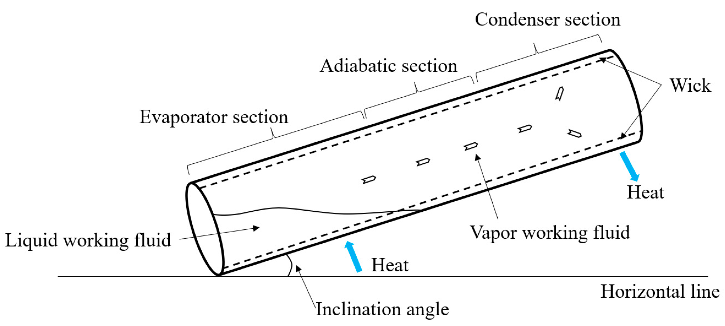
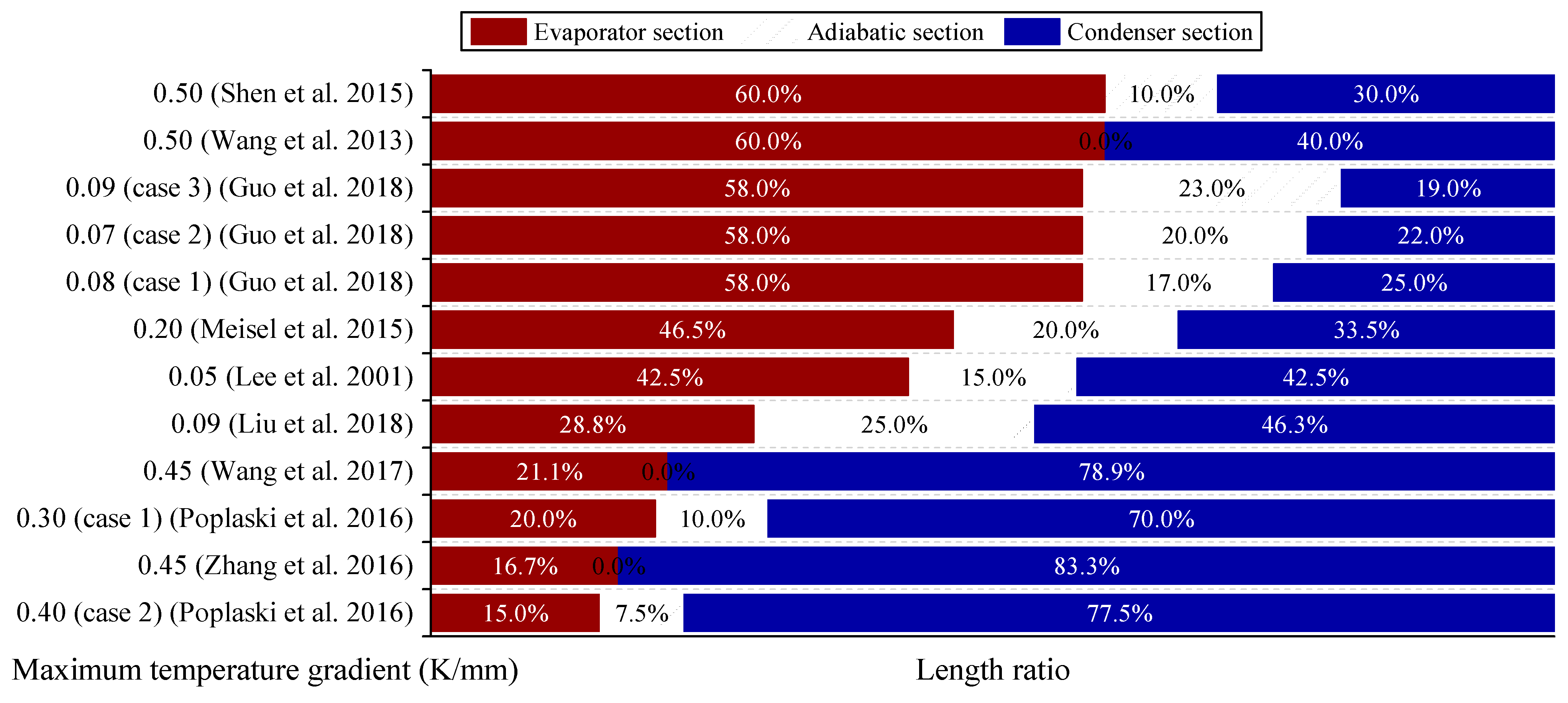
  • The length and shape of different sections of the heat pipe have obvious influences on the heat transfer and isothermal performance, and the change in the condenser length has no obvious effect on the axial temperature distribution or the heat transfer performance at higher heating temperatures. When the evaporator section is too short, the flow distance of working fluid in the con-denser section is long, which will lead to the accumulation of liquid working fluid at the inlet of the condenser section. When the evaporator section is too long, local overheating is easy to occur at the bottom of the evaporation section.
  • The evaporator easily overheats when the charge ratio is low, the start-up is much long, and the temperature difference inside the heat pipe is large when the charge ratio is high. Only when the charge ratio is appropriate can the heat pipe start and operate smoothly. The most suitable charge rate is 15–30% of the total inner volume.
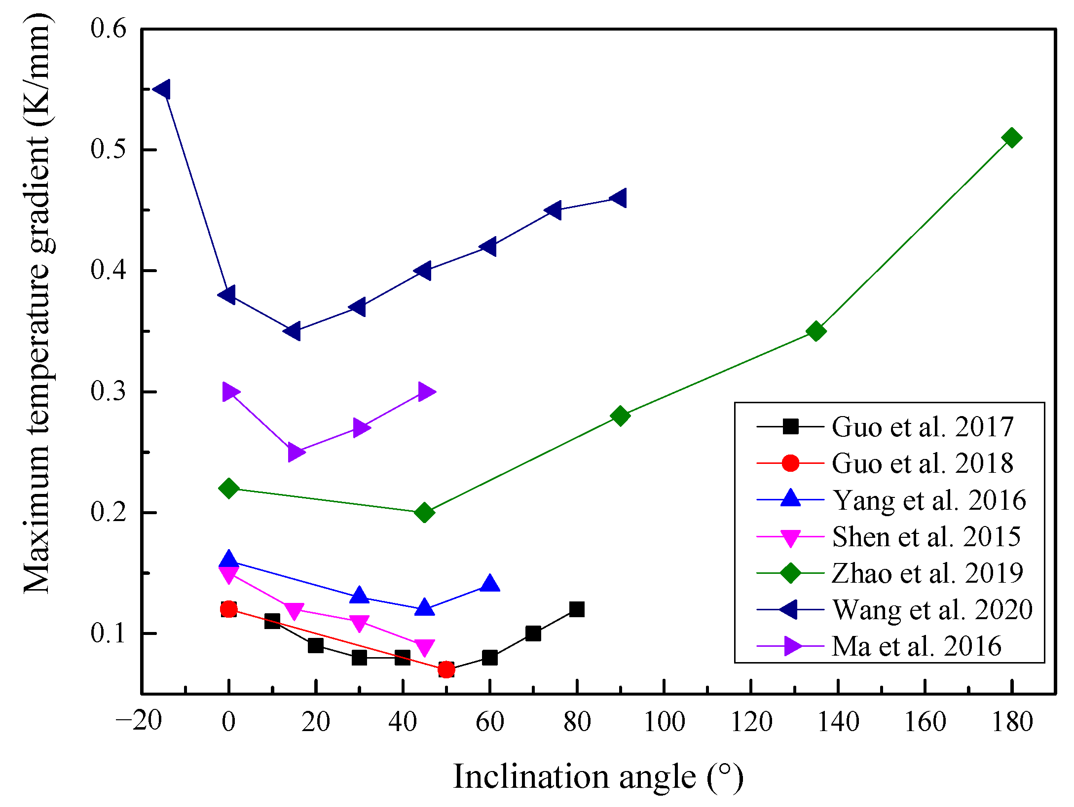
  • The inclination angle can affect the isothermal performance and the start-up performance of heat pipes, especially in condenser sections. The vertical distance along the gravity direction of the heat pipe decreases with an increasing inclination angle, and the effective heating area increases. However, the return-back resistance in the condenser section obviously increases due to the decrease in the component force of gravity. The heat pipes have the best isothermal performance when the inclination angle is approximately 45°.

Author Contributions

Literature curation, H.Z.; Formal analysis, H.Z.; Funding acquisition, F.Y. and X.Y.; Investigation, H.Z.; Project administration, F.Y. and X.Y.; Resources, F.Y. and X.Y.; Supervision, H.G. and F.Y.; Writing—Original draft, H.Z.; Writing—Review and editing, H.G. and F.Y. All authors listed have made a substantial, direct, and intellectual contribution to the work. All authors have read and agreed to the published version of the manuscript.

Funding

This work was funded by the National Key R&D Program of China [grant number 2017YFF0205901].

Institutional Review Board Statement

Not applicable.

Informed Consent Statement

Not applicable.

Data Availability Statement

The supporting data will be made available on request.

Conflicts of Interest

The authors declare no conflict of interest.

References

  1. Lee, B.I.; Lee, S.H. Manufacturing and temperature measurements of a sodium heat pipe. KSME Int. J. 2001, 15, 1533–1540. [Google Scholar] [CrossRef]
  2. Gaugler, R.S. Heat Transfer Device. U.S. Patent 2350348, 6 May 1944. [Google Scholar]
  3. Cotter, T.P. Theory of Heat Pipes; Los Alamos Scientific Laboratory: Los Alamos, NM, USA, 1965. [Google Scholar]
  4. Diver, R.B.; Fish, J.D.; Levitan, R.; Levy, M.; Meirovitch, E.; Rosin, H.; Paripatyadar, S.A.; Richardson, J.T. Solar test of an integrated sodium reflux heat pipe receiver/reactor for thermochemical energy transport. Sol. Energy 1992, 48, 21–30. [Google Scholar] [CrossRef]
  5. Mahboobe, M.; Qiu, S.G.; Saeed, T. Numerical investigation of hydrodynamics and thermal performance of a specially configured heat pipe for high-temperature thermal energy storage systems. Appl. Therm. Eng. 2015, 81, 325–337. [Google Scholar]
  6. Liao, Z.; Faghri, A. Thermal analysis of a heat pipe solar central receiver for concentrated solar power tower. Appl. Therm. Eng. 2016, 102, 952–960. [Google Scholar] [CrossRef]
  7. Choi, J.; Yuan, Y.; Borca-Tasciuc, D.A.; Kang, H. Design, construction and performance testing of an isothermal naphthalene heat pipe furnace. Rev. Sci. Instrum. 2014, 85, 95–105. [Google Scholar] [CrossRef]
  8. Marcarino, P.; Merlone, A. Gas-controlled heat-pipes for accurate temperature measurements. Appl. Therm. Eng. 2003, 23, 1145–1152. [Google Scholar] [CrossRef]
  9. Astrua, M.; Iacomini, L.; Battuello, M. The combined use of a gas-controlled heat pipe and a copper point to improve the calibration of thermocouples up to 1100 °C. Int. J. Thermophys. 2008, 29, 1838–1847. [Google Scholar] [CrossRef]
  10. Bertiglia, F.; Iacomini, L.; Moro, F.; Merlone, A. Comparison of two potassium-filled gas-controlled heat pipes. Int. J. Thermophys. 2015, 36, 3393–3403. [Google Scholar] [CrossRef]
  11. Chi, S.W. Heat Pipe Theory and Practice; Hemisphere Publishing Corp: New York, NY, USA, 1976. [Google Scholar]
  12. Faghri, A. Heat Pipe Science and Technology; Taylor & Francis: Washington, DC, USA, 1995. [Google Scholar]
  13. Busse, C.A. Theory of the ultimate heat transfer limit of cylindrical heat pipes. Int. J. Heat Mass Transf. 1973, 16, 169–186. [Google Scholar] [CrossRef]
  14. Demichele, D.W.; Davis, M.V. Vapor transport limits of liquid metal heat pipes. Nucl. Technol. 1972, 15, 366–383. [Google Scholar] [CrossRef]
  15. Kim, B.H.; Peterson, G.P. Analysis of the critical Weber number at the onset of liquid entrainment in capillary-driven heat pipes. Int. J. Heat Mass Transf. 1995, 38, 1427–1442. [Google Scholar] [CrossRef]
  16. Tournier, J.M.; Mohamed, S. A vapor flow model for analysis of liquid-metal heat pipe startup from a frozen state. Int. J. Heat Mass Transf. 1996, 39, 3767–3780. [Google Scholar] [CrossRef]
  17. Cao, Y.; Faghri, A. Closed-form analytical solutions of high-temperature heat pipe startup and frozen startup limitation. J. Heat Transf.-Trans. ASME 1992, 114, 1028–1035. [Google Scholar] [CrossRef]
  18. Jang, J.H. Startup characteristics of a potassium heat pipe from the frozen state. J. Thermophys. Heat Transf. 1995, 9, 117–122. [Google Scholar] [CrossRef]
  19. Guo, H.; Guo, Q.; Yan, X.K.; Ye, F.; Ma, C.F. Experimental investigation on heat transfer performance of high temperature thermosyphon charged with sodium-potassium alloy. Appl. Therm. Eng. 2018, 139, 402–408. [Google Scholar] [CrossRef]
  20. Wang, C.L.; Guo, Z.P.; Zhang, D.L.; Qiu, S.Z.; Tian, W.X.; Wu, Y.W.; Su, G.H. Transient behavior of the sodium-potassium alloy heat pipe in passive residual heat removal system of molten salt reactor. Prog. Nucl. Energy 2013, 68, 142–152. [Google Scholar] [CrossRef]
  21. Wang, C.L.; Zhang, D.L.; Qiu, S.Z.; Tian, W.X.; Wu, Y.W.; Su, G.H. Study on the characteristics of the sodium heat pipe in passive residual heat removal system of molten salt reactor. Nucl. Eng. Des. 2013, 265, 691–700. [Google Scholar] [CrossRef]
  22. Wang, C.L.; Chen, J.; Qiu, S.Z.; Tian, W.X.; Zhang, D.L.; Su, G.H. Performance analysis of heat pipe radiator unit for space nuclear power reactor. Ann. Nucl. Energy 2017, 103, 74–84. [Google Scholar] [CrossRef]
  23. Zhang, W.W.; Wang, C.L.; Chen, R.H.; Tian, W.X.; Qiu, S.Z.; Su, G.H. Preliminary design and thermal analysis of a liquid metal heat pipe radiator for TOPAZ-II power system. Ann. Nucl. Energy 2016, 97, 208–220. [Google Scholar] [CrossRef]
  24. Zhang, W.W.; Zhang, D.L.; Tian, W.X.; Qiu, S.Z.; Su, G.H. Thermal-hydraulic analysis of the improved TOPAZ-II power system using a heat pipe radiator. Nucl. Eng. Des. 2016, 307, 218–233. [Google Scholar] [CrossRef]
  25. Launay, S.; Sartre, V.; Bonjour, J. Parametric analysis of loop heat pipe operation: A literature review. Int. J. Therm. Sci. 2007, 46, 621–636. [Google Scholar] [CrossRef]
  26. Siedel, B.; Sartre, V.; Lefèvre, F. Literature review: Steady-state modelling of loop heat pipes. Appl. Therm. Eng. 2015, 75, 709–723. [Google Scholar] [CrossRef]
  27. Lips, S.; Sartre, V.; Lefèvre, F.; Khandekar, S.; Bonjour, J. Overview of heat pipe studies during the period 2010–2015. Interfacial Phenom. Heat Transf. 2016, 4, 33–53. [Google Scholar] [CrossRef]
  28. Ramezanizadeh, M.; Nazari, M.A.; Ahmadi, M.H.; Chau, K. Experimental and numerical analysis of a nanofluidic thermosyphon heat exchanger. Eng. Appl. Comp. Fluid Mech. 2019, 13, 40–47. [Google Scholar] [CrossRef]
  29. Shin, D.R.; Rhi, S.H.; Lim, T.K.; Jang, J.C. Comparative study on heat transfer characteristics of nanofluidic thermosyphon and grooved heat pipe. J. Mech. Sci. Technol. 2011, 25, 1391–1398. [Google Scholar] [CrossRef]
  30. Do, K.H.; Jang, S.P. Effect of nanofluids on the thermal performance of a flat micro heat pipe with a rectangular grooved wick. Int. J. Heat Mass Transf. 2010, 53, 2183–2192. [Google Scholar] [CrossRef]
  31. Wang, C.; Kazoe, Y.; Morikawa, K.; Shimizu, H.; Pihosh, Y.; Mawatari, K.; Kitamori, T. Micro heat pipe device utilizing extended nanofluidics. RSC Adv. 2017, 7, 50591–50597. [Google Scholar] [CrossRef] [Green Version]
  32. Jahani, K.; Mohammadi, M.; Shafii, M.B.; Shiee, Z. Promising technology for electronic cooling: Nanofluidic micro pulsating heat pipes. J. Electron. Packag. 2013, 135, 021005. [Google Scholar] [CrossRef]
  33. Boo, J.H.; Park, S.Y. Isothermal characteristics of a rectangular parallelepiped sodium heat pipe. J. Mech. Sci. Technol. 2005, 19, 1044–1051. [Google Scholar] [CrossRef]
  34. Xiao, G.M.; Du, Y.X.; Gui, Y.W.; Liu, L.; Yang, X.F.; Wei, D. Heat transfer characteristics and limitations analysis of heat-pipe-cooled thermal protection structure. Appl. Therm. Eng. 2014, 70, 655–664. [Google Scholar]
  35. Camarda, C.J.; Glass, D.E. Thermostructural applications of heat pipes for cooling leading edges of high-speed aerospace vehicles. In Current Technology for Thermal Protection Systems, Proceedings of a Workshop Sponsored by the National Aeronautics and Space Administration, Hampton, VA, USA, 11–12 February 1992; Scotti, S.J., Ed.; NASA Langley Research Center: Hampton, VA, USA, 1992; pp. 291–318. [Google Scholar]
  36. Li, T.; Jiang, Y.Y.; Li, Z.G.; Liu, Q.; Tang, D.W. Loop thermosiphon as a feasible cooling method for the stators of gas turbine. Appl. Therm. Eng. 2016, 109, 449–453. [Google Scholar] [CrossRef]
  37. Dillig, M.; Plankenbuhler, T.; Karl, J. Thermal effects of planar high temperature heat pipes in solid oxide cell stacks operated with internal methane reforming. J. Power Sources 2018, 373, 139–149. [Google Scholar] [CrossRef]
  38. Gui, X.; Xue, H.; Zhu, J.; Zhan, X.; Zhao, F. Study on inhibition characteristics of composite structure with high-temperature heat pipe and metal foam on gas explosion. Energies 2022, 15, 1135. [Google Scholar] [CrossRef]
  39. Peng, W.G.; He, Y.R.; Wang, X.Z.; Zhu, J.Q.; Han, J.C. Thermal protection mechanism of heat pipe in leading edge under hypersonic conditions. Chin. J. Aeronaut. 2015, 28, 121–132. [Google Scholar] [CrossRef] [Green Version]
  40. Liu, H.P.; Liu, W.Q. Thermal–structural analysis of the platelet heat-pipe-cooled leading edge of hypersonic vehicle. Acta Astronaut. 2016, 127, 13–19. [Google Scholar]
  41. David, R.; Adam, H. The role of heat pipes in intensified unit operations. Appl. Therm. Eng. 2013, 57, 147–153. [Google Scholar]
  42. Ahmad, M.; Adam, H.; David, R. Melting of phase change material assisted by expanded metal mesh. Appl. Therm. Eng. 2015, 90, 1052–1060. [Google Scholar]
  43. Wang, X.Y.; Ma, T.T.; Zhu, Y.Z.; Chen, H.J.; Zeng, J.L. Experimental investigation on startup and thermal performance of a high temperature special-shaped heat pipe coupling the flat plate heat pipe and cylindrical heat pipes. Exp. Therm. Fluid Sci. 2016, 77, 1–9. [Google Scholar] [CrossRef]
  44. Zhou, H.K.; Dai, C.H.; Liu, Y.; Fu, X.T.; Du, Y. Experimental investigation of battery thermal management and safety with heat pipe and immersion phase change liquid. J. Power Sources 2020, 473, 228545. [Google Scholar] [CrossRef]
  45. Vadiraj, A.H.; Ashish, G. Thermal radiators with embedded pulsating heat pipes: Infra-red thermography and simulations. Appl. Therm. Eng. 2011, 31, 1332–1346. [Google Scholar]
  46. Reyes, M.; Alonso, D.; Arias, J.R.; Velazquez, A. Experimental and theoretical study of a vapor chamber based heat spreader for avionics applications. Appl. Therm. Eng. 2012, 37, 51–59. [Google Scholar] [CrossRef]
  47. Boukhanouf, R.; Haddad, A.; North, M.T.; Buffone, C. Experimental investigation of a flat heat pipe performance using IR thermal imaging camera. Appl. Therm. Eng. 2006, 26, 2148–2156. [Google Scholar] [CrossRef]
  48. Sun, J.Y.; Chain, T.; Shih, D.K.; Wang, C.Y. High-efficiency Isothermal Heat Pipe. U.S. Patent 005465782A, 14 November 1995. [Google Scholar]
  49. Bienert, W.B. The heat pipe and its application to solar receivers. Electr. Power Syst. Res. 1980, 3, 111–123. [Google Scholar] [CrossRef]
  50. Xu, H.; Shen, Y.; Yu, P.; Bai, T.; Zhang, H. Study on heat transfer of high temperature heat pipe solar receiver. Int. J. Environ. Res. 2013, 8, 1473–1480. [Google Scholar]
  51. Cui, H.; Wang, Z.; Guo, Y.; Xu, W.Q.; Yuan, X.G. Thermal performance analysis on unit tube for heat pipe receiver. Sol. Energy 2006, 80, 875–882. [Google Scholar] [CrossRef]
  52. Sharifi, N.; Faghri, A.; Bergman, T.L.; Andraka, C.E. Simulation of heat pipe-assisted latent heat thermal energy storage with simultaneous charging and discharging. Int. J. Heat Mass Transf. 2015, 80, 170–179. [Google Scholar] [CrossRef] [Green Version]
  53. Hansen, G.; Ness, E.; Kristjansson, K. Analysis of a vertical flat heat pipe using potassium working fluid and a wick of compressed nickel foam. Energies 2016, 9, 170–187. [Google Scholar] [CrossRef] [Green Version]
  54. Fan, A.; Bonner, R.; Sharratt, S.; Sungtaek, Y. An innovative passive cooling method for high performance light-emitting diodes. In Proceedings of the 28th Annual IEEE SEMI-THERM, San Jose, CA, USA, 18–22 May 2012; pp. 319–324. [Google Scholar]
  55. Hsu, H.C. Isothermal Plate Module. U.S. Patent 20080035310A1, 8 September 2006. [Google Scholar]
  56. Chen, J.; Dong, J.; Yao, Y. Experimental study on the starting-up and heat transfer characteristics of a pulsating heat pipe under local low-frequency vibrations. Energies 2021, 14, 6310. [Google Scholar] [CrossRef]
  57. Chen, J.; Yuan, D.; Jiang, H.; Zhang, L.; Yang, Y.; Fu, Y.; Qian, N.; Jiang, F. Thermal management of bone drilling based on rotating heat pipe. Energies 2022, 15, 35. [Google Scholar] [CrossRef]
  58. Campo, D.; Weyant, J.; Muzyka, B. Enhancing thermal performance in embedded computing for ruggedized military and avionics applications. In Proceedings of the 14th IEEE ITHERM Conference, Orlando, FL, USA, 27–30 May 2014; pp. 840–845. [Google Scholar]
  59. Tsai, M.; Kang, S.; Vieira, K. Experimental studies of thermal resistance in a vapor chamber heat spreader. Appl. Therm. Eng. 2013, 56, 38–44. [Google Scholar] [CrossRef]
  60. Zhang, H.; Ye, F.; Guo, H.; Yan, X. Sodium-potassium alloy heat pipe under geyser boiling experimental study: Heat transfer analysis. Energies 2021, 14, 7582. [Google Scholar] [CrossRef]
  61. Tang, Y.; Hu, Z.; Qing, J.; Xie, Z.; Fu, T.; Chen, W. Experimental investigation on isothermal performance of the micro-grooved heat pipe. Exp. Therm. Fluid Sci. 2013, 47, 143–149. [Google Scholar] [CrossRef]
  62. Lim, C.; Choi, J.; Kim, H. Experimental investigation of the heat transfer characteristics and operation limits of a fork-type heat pipe for passive cooling of a spent fuel pool. Energies 2021, 14, 7862. [Google Scholar] [CrossRef]
  63. Bernagozzi, M.; Miché, N.; Georgoulas, A.; Rouaud, C.; Marengo, M. Performance of an environmentally friendly alternative fluid in a loop heat pipe-based battery thermal management system. Energies 2021, 14, 7738. [Google Scholar] [CrossRef]
  64. Wang, J.C.; Wang, R.T.; Chang, T.L.; Hwang, D.S. Development of 30W high power LEDs vapor chamber-based plate. Int. J. Heat Mass Transf. 2010, 53, 3990–4001. [Google Scholar] [CrossRef]
  65. Giunta, S.; Merlone, A.; Marenco, S.; Marcarino, P.; Tiziani, A. Capabilities of a new pressure controller for gas-controlled heat pipes. Int. J. Thermophys. 2008, 29, 1887–1895. [Google Scholar] [CrossRef]
  66. Boo, J.H.; Kim, S.M.; Kang, Y.H. An experimental study on a sodium loop-type heat pipe for thermal transport from a high-temperature solar receiver. In Proceedings of the SolarPACES, Beijing, China, 16–19 September 2015; pp. 608–617. [Google Scholar]
  67. Sanchez, F.S.; Carvajal, I.M.; Morino, A.E.; Diez, P.Q.; Velazquez, M.T. Study of an annular two-phase thermosyphon used as an isothermal source in thermometry. J. Mech. Eng. 2015, 61, 273–282. [Google Scholar] [CrossRef]
  68. Yan, X.K.; Duan, Y.N.; Ma, C.F.; Lv, Z.F. Construction of sodium heat-pipe furnaces and the isothermal characteristics of the furnaces. Int. J. Thermophys. 2011, 32, 494–504. [Google Scholar] [CrossRef]
  69. Wu, F.; Song, D.; Yi, X.; Yu, Z.; Sheng, K.; Wu, J. Cesium heat-pipe thermostat. In Proceedings of the 9th International Temperature Symposium on Temperature-Its Measurement and Control in Science and Industry, Los Angeles, CA, USA, 19–23 March 2012; pp. 830–833. [Google Scholar]
  70. Yan, X.K.; Zhang, J.T.; Merlone, A.; Duan, Y.; Wang, W. NIM gas controlled sodium heat pipe. In Proceedings of the 9th International Temperature Symposium on Temperature-Its Measurement and Control in Science and Industry, Los Angeles, CA, USA, 19–23 March 2012; pp. 834–839. [Google Scholar]
  71. Joung, W.; Kim, Y.G.; Yang, I.; Gam, K.S. Operating characteristics of a loop heat pipe-based isothermal region generator. Int. J. Heat Mass Transf. 2013, 65, 460–470. [Google Scholar] [CrossRef]
  72. Shen, Y.; Zhang, H.; Xu, H.; Yu, P.; Bai, T. Maximum heat transfer capacity of high temperature heat pipe with triangular grooved wick. J. Cent. South Univ. 2015, 22, 386–391. [Google Scholar] [CrossRef]
  73. Rosenfeld, J.H.; Ernst, D.M.; Lindemuth, J.E.; Sanzi, J.L.; Geng, S.M.; Zuo, J. An overview of long duration sodium heat pipe tests. AIP Conf. Proc. 2004, 699, 140–147. [Google Scholar]
  74. Andraka, C.E.; Moss, T.A.; Baturkin, V.; Zaripov, V.; Nishchyk, O. High performance felt-metal-wick heat pipe for solar receivers. In Proceedings of the International Conference on Concentrating Solar Power & Chemical Energy Systems, Cape Town, South Africa, 13–16 October 2015. [Google Scholar]
  75. Zhao, J.; Yuan, D.Z.; Tang, D.W.; Jiang, Y.Y. Heat transfer characteristics of a concentric annular high temperature heat pipe under anti-gravity conditions. Appl. Therm. Eng. 2019, 148, 817–824. [Google Scholar] [CrossRef]
  76. Li, B.T.; Yin, X.X.; Tang, W.H.; Zhang, J.H. Optimization design of grooved evaporator wick structures in vapor chamber heat spreaders. Appl. Therm. Eng. 2020, 166, 114657. [Google Scholar] [CrossRef]
  77. Luo, Y.Q.; Liu, W.Y.; Huang, G.W. Fabrication and experimental investigation of the bionic vapor chamber. Appl. Therm. Eng. 2020, 168, 114889. [Google Scholar] [CrossRef]
  78. Panda, K.; Dulera, I.; Basak, A. Numerical simulation of high temperature sodium heat pipe for passive heat removal in nuclear reactors. Nucl. Eng. Des. 2017, 323, 376–385. [Google Scholar] [CrossRef]
  79. Hu, Z.H.; Wang, D.C.; Xu, J.Y.; Zhang, L. Development of a loop heat pipe with the 3D printed stainless steel wick in the application of thermal management. Int. J. Heat Mass Transf. 2020, 161, 120258. [Google Scholar] [CrossRef]
  80. Liang, L.; Diao, Y.H.; Zhao, Y.H.; Wang, Z.Y.; Bai, F.W. Numerical and experimental investigations of latent thermal energy storage device based on a flat micro-heat pipe array-metal foam composite structure. Renew. Energy 2020, 161, 1195–1208. [Google Scholar] [CrossRef]
  81. Wang, G.; Quan, Z.H.; Zhao, Y.H.; Wang, H.Y. Effect of geometries on the heat transfer characteristics of flat-plate micro heat pipes. Appl. Therm. Eng. 2020, 180, 115796. [Google Scholar] [CrossRef]
  82. Zhao, W.L.; Zhuang, J.; Zhang, H. Influences of the evaporator length and liquid-filled content on the startup operation of the high temperature sodium heat pipes. Chem. Eng. Mach. 2003, 30, 259–262. [Google Scholar]
  83. Ma, T.T.; Zhu, Y.Z.; Chen, H.J.; Wang, X.Y.; Zeng, J.L.; Lu, B.B. Frozen start-up performance of a high temperature special shaped heat pipe suitable for solar thermochemical reactors. Appl. Therm. Eng. 2016, 109, 591–599. [Google Scholar] [CrossRef]
  84. Poplaski, L.M.; Faghri, A.; Bergman, T.L. Analysis of internal and external thermal resistances of heat pipes including fins using a three-dimensional numerical simulation. Int. J. Heat Mass Transf. 2016, 102, 455–469. [Google Scholar] [CrossRef] [Green Version]
  85. Meisel, P.; Jobst, M.; Lippmann, W.; Hurtado, A. Design and manufacture of ceramic heat pipes for high temperature applications. Appl. Therm. Eng. 2015, 75, 692–699. [Google Scholar] [CrossRef]
  86. Liu, M.H.; Zhang, D.L.; Wang, C.L.; Qiu, S.Z.; Su, G.H.; Tian, W.X. Experimental study on heat transfer performance between fluoride salt and heat pipes in the new conceptual passive residual heat removal system of molten salt reactor. Nucl. Eng. Des. 2018, 339, 215–224. [Google Scholar] [CrossRef]
  87. Wang, C.L.; Liu, L.; Liu, M.H.; Zhang, D.L.; Tian, W.X.; Qiu, S.Z.; Su, G.H. Conceptual design and analysis of heat pipe cooled silo cooling system for the transportable fluoride-salt-cooled high-temperature reactor. Ann. Nucl. Energy 2017, 109, 458–468. [Google Scholar] [CrossRef]
  88. Lu, Q.; Han, H.T.; Hu, L.F.; Chen, S.Y.; Yu, J.J.; Ai, B.C. Preparation and testing of nickel-based superalloy/sodium heat pipes. Heat Mass Transf. 2017, 53, 3391–3397. [Google Scholar] [CrossRef]
  89. Hack, N.; Unz, S.; Beckmann, M. Ceramic heat pipes for high temperature application. Energy Procedia 2017, 120, 140–148. [Google Scholar] [CrossRef]
  90. Ma, T.T.; Ren, T.Q.; Chen, H.J.; Zhu, Y.Z.; Zhu, S.L.; Ji, G.J. Thermal performance of a solar high temperature thermochemical reactor powered by a solar simulator. Appl. Therm. Eng. 2019, 146, 881–888. [Google Scholar] [CrossRef]
  91. Guo, Q.; Guo, H.; Yan, X.K.; Ye, F.; Ma, C.F. Influence of inclination angle on the start-up performance of a sodium-potassium alloy heat pipe. Heat Transf. Eng. 2017, 39, 1631–1640. [Google Scholar] [CrossRef]
  92. Wang, C.L.; Zhang, L.R.; Liu, X.; Tang, S.M.; Qiu, S.Z.; Su, G.H. Experimental study on startup performance of high temperature potassium heat pipe at different inclination angles and input powers for nuclear reactor application. Ann. Nucl. Energy 2020, 136, 107051. [Google Scholar] [CrossRef]
  93. Yang, L.; Zhou, R.W.; Jin, X.G.; Ling, X.; Peng, H. Experimental investigate on thermal properties of a novel high temperature flat heat pipe receiver in solar power tower plant. Appl. Therm. Eng. 2016, 109, 610–618. [Google Scholar] [CrossRef]
Figure 1. Working process and influencing factors of the isothermal performance of heat pipes.
Energies 15 01992 g001
Figure 2. Effect of the isothermal performance on length ratio of each section of heat pipes.
Energies 15 01992 g002
Figure 3. Effect of the isothermal performance on inclination angle of heat pipes.
Energies 15 01992 g003
Table 1. Common types of heat pipe in isothermal applications.
Type of Heat PipeIsothermal Region
Cylindrical heat pipeCylindrical surface (Curved surface)
Flat heat pipeEvaporator surface (Two dimensional plane)
Loop heat pipeCondenser surface
Pulsating heat pipeCondenser section (Curved surface)
Annular heat pipeInner pipe (Three-dimensional space)
Table 2. Characteristics of heat pipes for isothermal performance in thermal protection.
Maximum Temperature GradientType of Heat PipeReference
With Heat Pipes/K/mmWithout Heat Pipes/K/mm
0.91.9Capillary heat pipeXiao et al. [34]
0.9-Capillary heat pipeGui et al. [38]
0.64.4Capillary heat pipePeng et al. [39]
0.44.2Capillary heat pipeLiu et al. [40]
0.252.1Capillary heat pipeDillig et al. [37]
0.25.0Capillary heat pipeCamarda et al. [35]
0.150.81Capillary heat pipeLi et al. [36]
Table 3. Characteristics of heat pipes for isothermal performance of isothermal reactors.
Maximum Temperature Gradient/K/mmType of Heat PipeReference
0.30Flat heat pipeWang et al. [43]
0.22ThermosyphonAhmad et al. [42]
0.03Capillary heat pipeDiver et al. [4]
0.02ThermosyphonWang et al. [20]
0.01Annular heat pipeChoi et al. [7]
Table 4. Characteristics of heat pipes for isothermal performance in thermal management.
Maximum Temperature GradientType of Heat PipeReference
With Heat Pipes/K/mmWithout Heat Pipes/K/mm
2.215.6Flat heat pipeFan et al. [54]
0.300.80Capillary heat pipeHsu [55]
0.15-Pulsating heat pipeChen et al. [56]
0.14-Rotating heat pipeChen et al. [57]
0.110.19Pulsating heat pipeVadiraj et al. [45]
0.100.90Flat heat pipeSun et al. [48]
0.080.32Flat heat pipeBoukhanouf et al. [47]
0.060.25Capillary heat pipeCampo et al. [58]
0.05-Flat heat pipeTsai et al. [59]
0.05-ThermosyphonZhang et al. [60]
0.020.08Capillary heat pipeTang et al. [61]
0.020.12Capillary heat pipeLim et al. [62]
0.01-Loop heat pipeBernagozzi et al. [63]
0.010.12Flat heat pipeWang et al. [64]
Table 5. Characteristics of heat pipes for isothermal performance of in metrology.
Maximum Temperature Gradient/K/mmType of Heat PipeReference
0.02ThermosyphonSanchez et al. [67]
0.0005ThermosyphonWu et al. [69]
0.0004Loop heat pipeJoung et al. [71]
0.0003Annular capillary heat pipeYan et al. [68]
0.0003Gas controlled capillary heat pipeBertiglia et al. [10]
0.0002Gas controlled thermosyphonYan et al. [70]
0.0001Gas controlled thermosyphonMarcarino et al. [8]
Table 6. Effect of the isothermal performance on different wicks of heat pipes.
Maximum Temperature Gradient/K/mmShape of Heat PipeWick StructureWick ParameterReference
1.7Short cuboidScreen mesh50 meshBoo et al. [33]
0.6AnnularScreen mesh400 meshZhao et al. [75]
0.4Long cuboidScreen mesh100 meshPanda et al. [78]
0.12Loop3D printed mesh0.3–0.6 (porosity)Hu et al. [79]
0.1FlatMicro channel1 mm (depth)Liang et al. [80]
0.05CylindricalScreen mesh60 meshLee et al. [1]
Table 7. Effect of the isothermal performance on length ratio of each section of heat pipes.
Length Ratio of EvaporatorLength Ratio of Adiabatic SectionLength Ratio of CondenserTotal Length/mmMaximum Temperature Gradient/K/mmReference
0.6000.1000.3004000.50Shen et al. [72]
0.60000.2406000.50Wang et al. [20]
0.5800.1700.25010000.08Guo et al. [19] (case 1)
0.5800.2000.22010000.07Guo et al. [19] (case 2)
0.5800.2300.19010000.09Guo et al. [19] (case 3)
0.4650.2000.3357750.20Meisel et al. [85]
0.4250.1500.42510000.05Lee et al. [1]
0.2880.2500.4628000.09Liu et al. [86]
0.21100.7897350.45Wang et al. [87]
0.2000.1000.7005000.30Poplaski et al. [84] (case 1)
0.16700.8336000.45Zhang et al. [23]
0.1500.0750.7757000.40Poplaski et al. [84] (case 2)
Table 8. Effect of the isothermal performance on working fluid charge ratio of heat pipes.
Optimum Working Fluid Charge RatioMass of Working Fluid/gMaximum Temperature Gradient/K/mmReference
29.1% of the total inner volume600.15Shen et al. [72]
27.7% of the total inner volume2000.12Ma et al. [90]
24.9% of the total inner volume700.08Guo et al. [19]
20% of the total inner volume65.70.15Lee et al. [1]
16.6% of the total inner volume1200.30Ma et al. [83]
15.6% of the total inner volume;380.50Panda et al. [78]
15% of the total inner volume-0.45Zhao et al. [75]
Table 9. Effect of the isothermal performance on inclination angle of heat pipes.
Optimum Isothermal Performance Inclination AngleMaximum Temperature Gradient/K/mmTest AngleReference
50°0.070°, 10°, 20°, 30°, 40°, 50°, 60°, 70° and 80°Guo et al. [91]
50°0.070° and 50°Guo et al. [19]
45°0.120°, 30°, 45° and 60°Yang et al. [93]
45°0.090°, 15°, 30° and 45°Shen et al. [72]
45°0.200°, 45°, 90°, 135° and 180°Zhao et al. [75]
15°0.35−15°, 0°, 15°, 30°, 45°, 60°, 75° and 90°Wang et al. [92]
15°0.250°, 15°, 30° and 45°Ma et al. [83]
Publisher’s Note: MDPI stays neutral with regard to jurisdictional claims in published maps and institutional affiliations.

