
A Review of the Power Battery Thermal Management System with Different Cooling, Heating and Coupling System

 ,
, 
Abstract
:1. Introduction
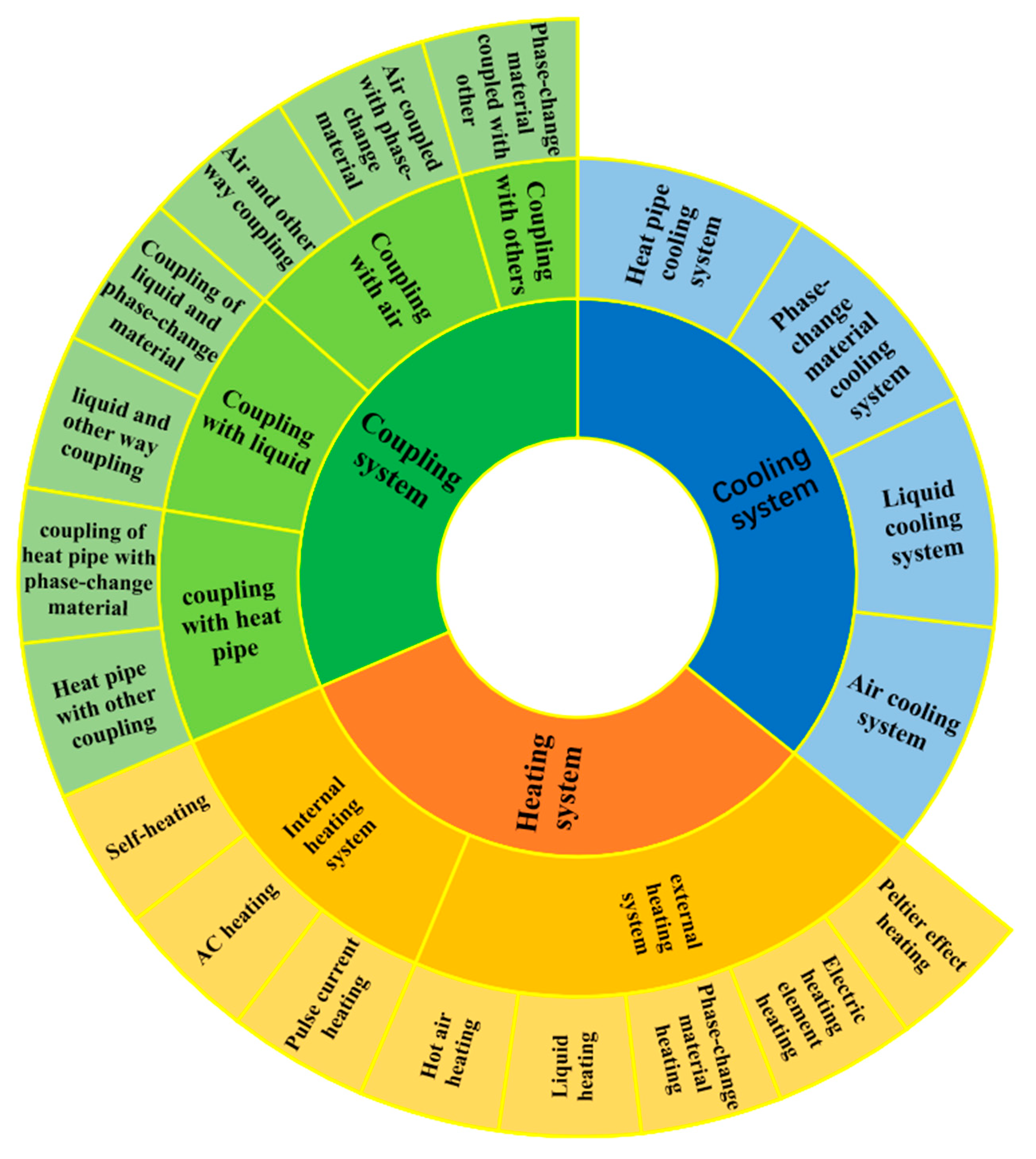
2. Cooling System
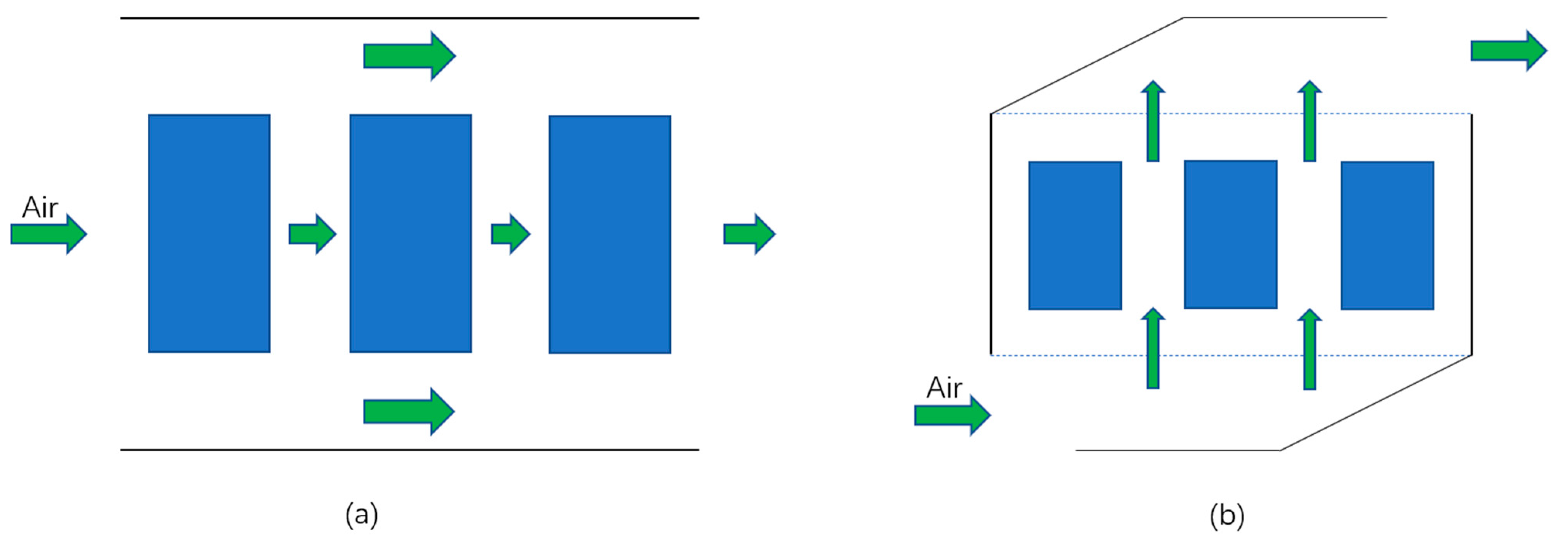
2.1. Air Cooling System
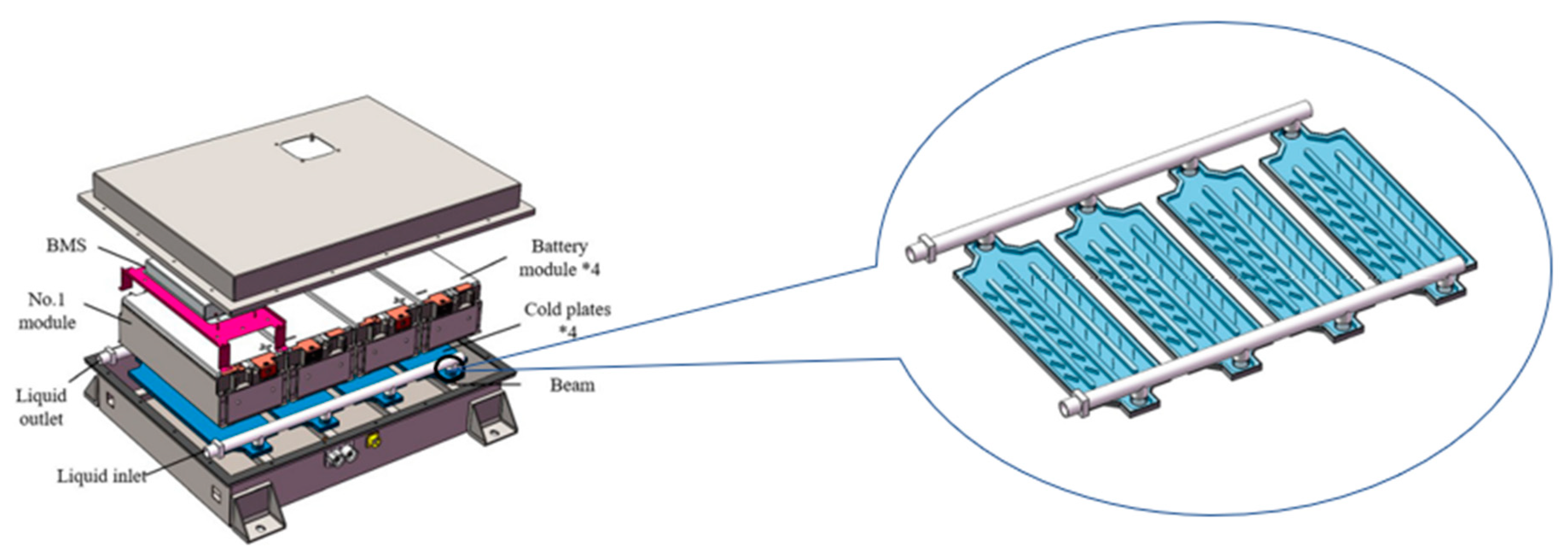
2.2. Liquid Cooling System
2.3. Phase Change Material Cooling System
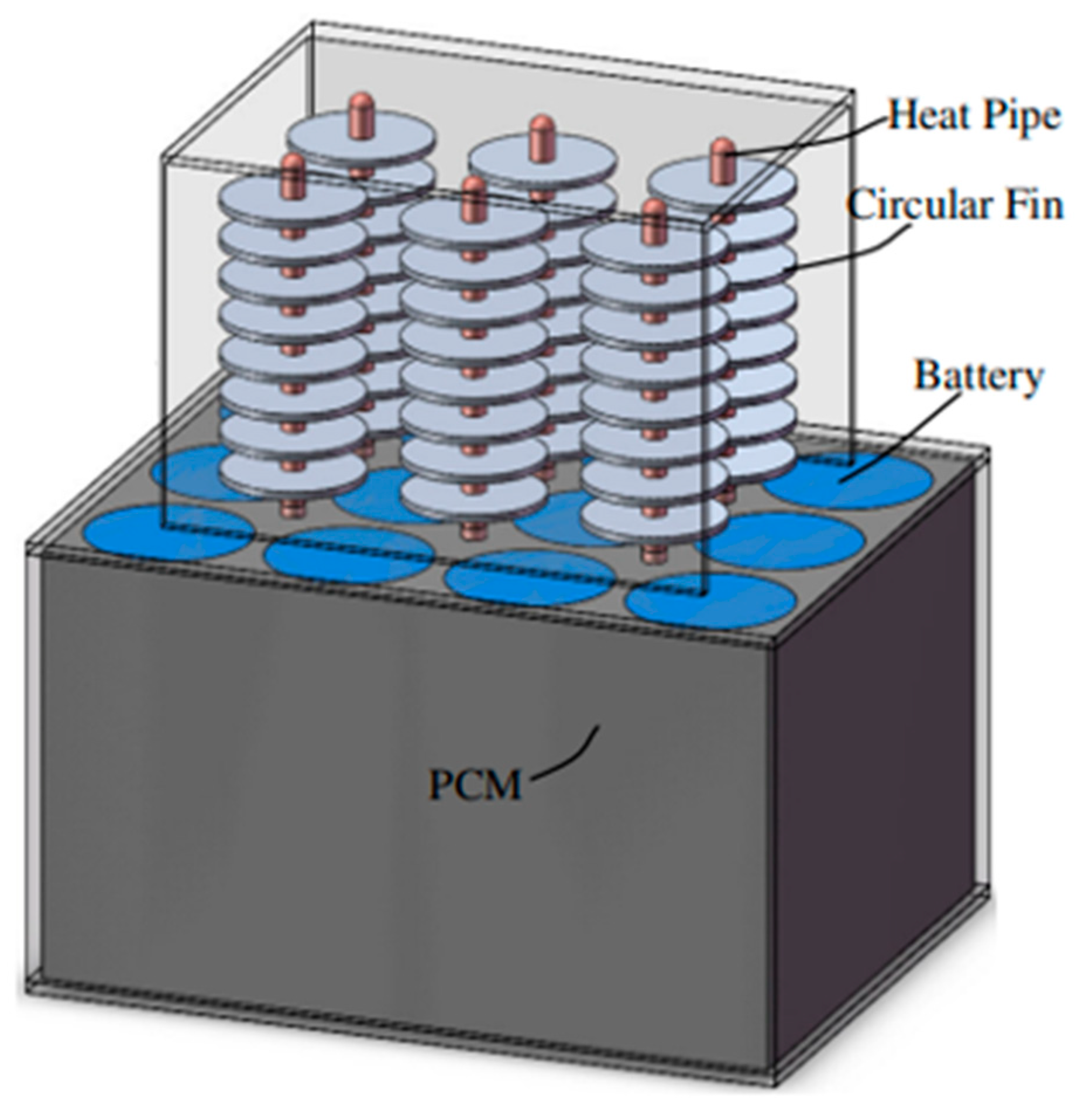
2.4. Heat Pipe Cooling System
3. Heating System
3.1. Internal Heating System
- (1)
- Self-heating
- (2)
- AC heating
- (3)
- Pulse current heating
3.2. External Heating System
- (1)
- Hot air heating
- (2)
- Liquid heating
- (3)
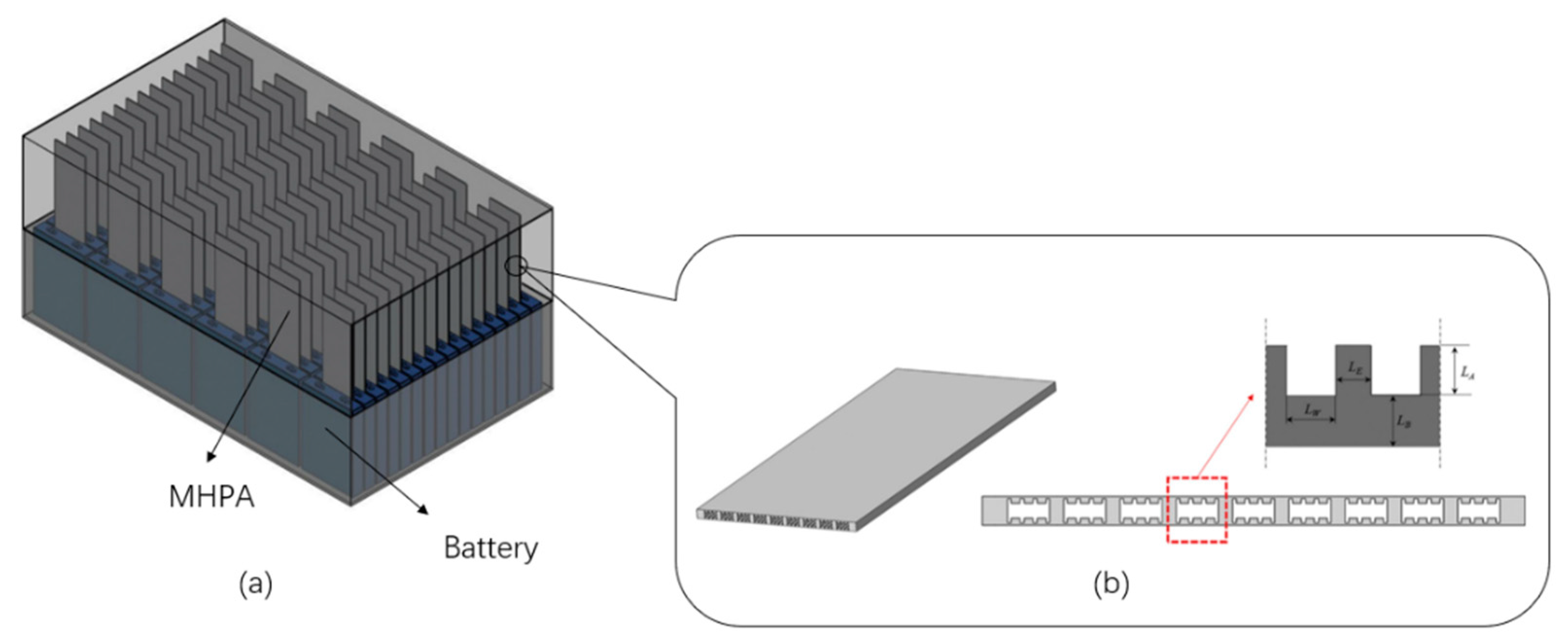
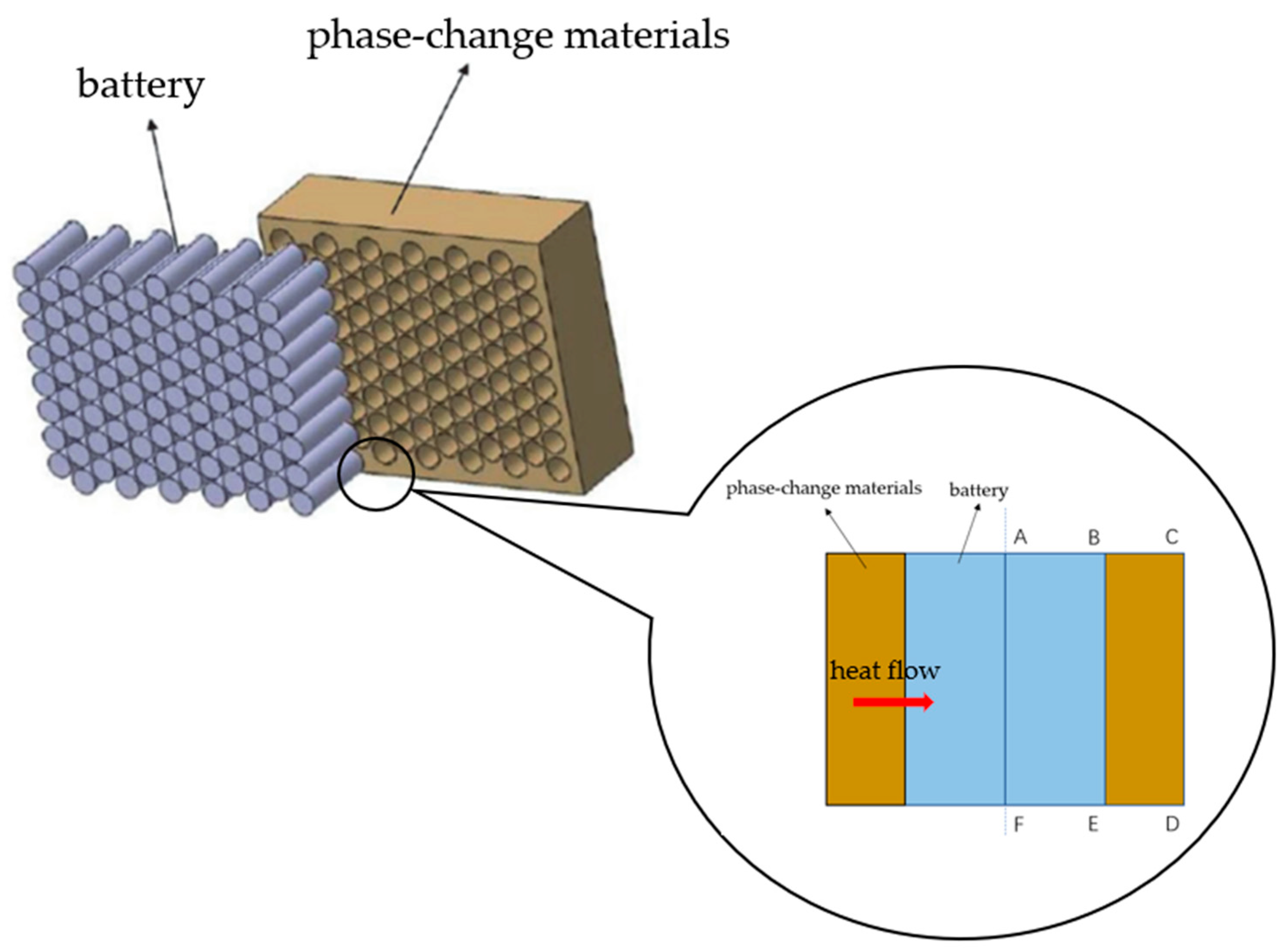
- Phase-change material heating
- (4)
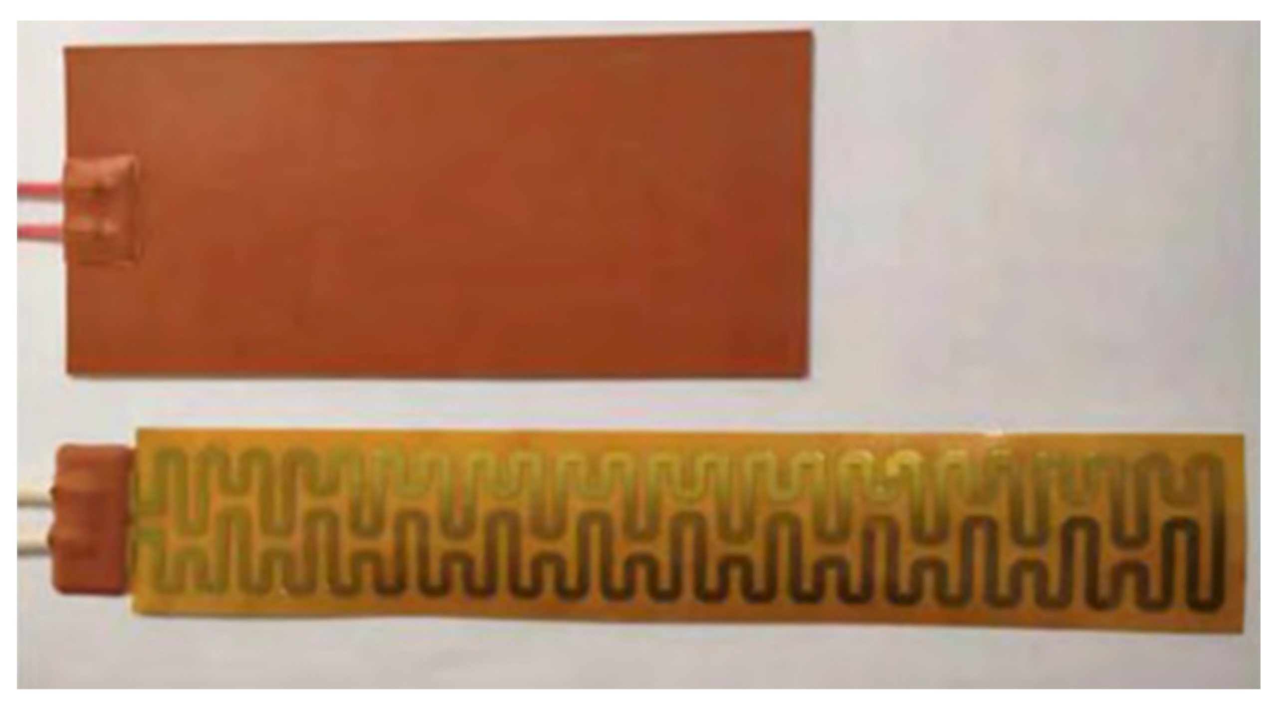
- Electric heating element heating
- (5)
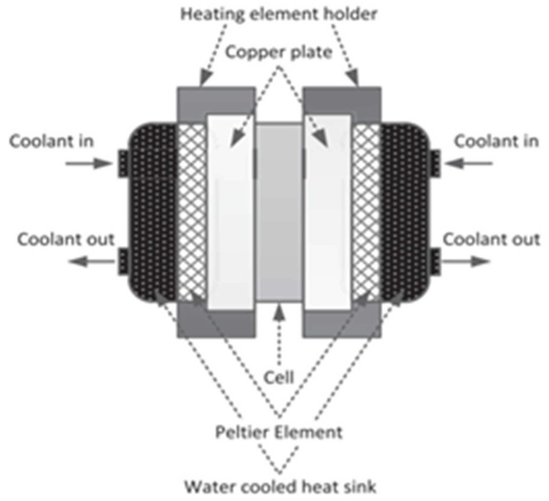
- Peltier effect heating
4. Coupling System
4.1. Coupling with Air
- (1)
- Air coupled with phase-change material
- (2)
- Air and other way couplings
4.2. Coupling with Liquid
- (1)
- Coupling of liquid and phase-change material
- (2)
- Liquid and other way couplings
4.3. Coupling with Heat Pipe
- (1)
- Coupling of heat pipe with phase-change material
- (2)
- Heat pipe with other couplings
4.4. Coupling Phase Change Material Coupled with Other
5. Conclusions
Author Contributions
Funding
Acknowledgments
Conflicts of Interest
References
- Andersen, P.H.; Mathews, J.A.; Rask, M. Integrating private transport into renewable energy policy: The strategy of creating intelligent recharging grids for electric vehicles. Energy Policy 2009, 37, 2481–2486. [Google Scholar] [CrossRef]
- Teixeira AC, R.; Sodré, J.R. Impacts of replacement of engine powered vehicles by electric vehicles on energy consumption and CO2 emissions. Transp. Res. D Transp. Environ. 2018, 59, 375–384. [Google Scholar] [CrossRef]
- Wang, Q.; Ping, P.; Zhao, X.; Chu, G.; Sun, J.; Chen, C. Thermal runaway caused fire and explosion of lithium-ion battery. J. Power Sources 2012, 208, 210–224. [Google Scholar] [CrossRef]
- Spitthoff, L.; Shearing, P.R.; Burheim, O.S. Temperature, Ageing and Thermal Management of Lithium-Ion Batteries. Energies 2021, 14, 1248. [Google Scholar] [CrossRef]
- Yang, S.; Ling, C.; Fan, Y.; Yang, Y.; Tan, X.; Dong, H. A review of lithium-ion battery thermal management system strategies and the evaluate criteria. Int. J. Electrochem. Sci. 2019, 14, 6077–6107. [Google Scholar] [CrossRef]
- Lu, Z.; Yu, X.; Wei, L.; Qiu, Y.; Zhang, L.; Meng, X.; Jin, L. Parametric study of forced air-cooling strategy for lithium- ion battery pack with staggered arrangement. Appl. Therm. Eng. 2018, 136, 28–40. [Google Scholar] [CrossRef]
- Zhang, T.; Gao, Q.; Wang, G.; Gu, Y.; Wang, Y.; Bao, W.; Zhang, D. Investigation on the promotion of temperature uniformity for the designed Battery Pack with Liquid Flow in cooling process. Appl. Therm. Eng. 2017, 116, 655–662. [Google Scholar] [CrossRef]
- Ianniciello, L.; Biwole, P.H.; Achard, P. Electric vehicles batteries thermal management systems employing phase change materials. J. Power Sources 2018, 378, 383–403. [Google Scholar] [CrossRef]
- Xie, Y.; Tang, J.; Shi, S.; Xing, Y.; Wu, H.; Hu, Z.; Wen, D. Experimental and numerical investigation on integrated thermal management for lithium- ion battery pack with composite phase change materials. Energy Convers. Manag. 2017, 154, 562–575. [Google Scholar] [CrossRef] [Green Version]
- Feng, L.; Zhou, S.; Li, Y.; Wang, Y.; Zhao, Q.; Luo, C.; Wang, G.; Yan, K. Experimental investigation of thermal and strain management for lithium- ion battery pack in heat pipe cooling. J. Energy Storage 2018, 16, 84–92. [Google Scholar] [CrossRef]
- Wu, S.; Xiong, R.; Li, H.; Nian, V.; Ma, S. The state of the art on preheating lithium-ion batteries in cold weather. J. Energy Storage 2020, 27, 101059. [Google Scholar] [CrossRef]
- Wang, C.Y.; Zhang, G.; Ge, S.; Xu, T.; Ji, Y.; Yang, X.G.; Leng, Y. Lithium-ion battery structure that self-heats at low temperatures. Nature 2016, 529, 515–518. [Google Scholar] [CrossRef] [PubMed]
- Zhu, J.; Sun, Z.; Wei, X.; Dai, H. An alternating current heating method for lithium-ion batteries from subzero temperatures. Int. J. Energy Res. 2016, 40, 1869–1883. [Google Scholar] [CrossRef]
- Zhu, J.; Sun, Z.; Wei, X.; Dai, H.; Gu, W. Experimental investigations of an AC pulse heating method for vehicular high power lithium-ion batteries at subzero temperatures. J. Power Sources 2017, 367, 145–157. [Google Scholar] [CrossRef]
- Rao, Z.H.; Wang, Y.L.; Zhang, Y.L. Thermal Management with Phase Change Material for a Power Battery under Cold Temperatures. Energy Sources Part A 2014, 36, 2287–2295. [Google Scholar] [CrossRef]
- Jin, X.; Li, J.; Zhang, C.; Wu, P. Researches on modeling and experiment of Li-ion battery PTC self-heating in electric vehicles. Energy Procedia 2016, 104, 62–67. [Google Scholar] [CrossRef]
- Zhang, S.; Shen, W. Rule-Based Control of Battery External Heating for Electric Vehicle during Driving at Low Temperatures. IEEE Access 2021, 9, 149360–149371. [Google Scholar] [CrossRef]
- Alaoui, C.; Salameh, Z.M. A Novel Thermal Management for Electric and Hybrid Vehicles. IEEE Trans. Veh. Technol. 2005, 54, 468–476. [Google Scholar] [CrossRef]
- Goutam, S.; Timmermans, J.M.; Omar, N.; Bossche, P.V.D.; Van Mierlo, J. Comparative study of surface temperature behavior of commercial li-ion pouch cells of different chemistries and capacities by infrared thermography. Energies 2015, 8, 8175–8192. [Google Scholar] [CrossRef] [Green Version]
- Rugh, J.P.; Pesaran, A.; Smith, K. Electric Vehicle Battery Thermal Issues and Thermal Management Techniques (Presentation); National Renewable Energy Laboratory (NREL): Golden, CO, USA, 2013. [Google Scholar]
- Saw, L.H.; Poon, H.M.; San Thiam, H.; Cai, Z.; Chong, W.T.; Pambudi, N.A.; King, Y.J. Novel thermal management system using mist cooling for lithium-ion battery packs. Appl. Energy 2018, 223, 146–158. [Google Scholar] [CrossRef] [Green Version]
- Aris, A.M.; Shabani, B. An experimental study of a lithium ion cell operation at low temperature conditions. Energy Procedia 2017, 110, 128–135. [Google Scholar] [CrossRef]
- Yang, T.; Yang, N.; Zhang, X.; Li, G. Investigation of the thermal performance of axial-flow air cooling for the lithium-ion battery pack. Int. J. Therm. Sci. 2016, 108, 132–144. [Google Scholar] [CrossRef]
- Na, X.; Kang, H.; Wang, T.; Wang, Y. Reverse layered air flow for Li-ion battery thermal management. Appl. Therm. Eng. 2018, 143, 257–262. [Google Scholar] [CrossRef]
- Ikezoe, M.; Hirata, N.; Amemiya, C.; Miyamoto, T.; Watanabe, Y.; Hirai, T.; Sasaki, T. Development of High Capacity Lithium-Ion Battery for Nissan Leaf; SAE Technical Paper; SAE International: Warrendale, PA, USA, 2012. [Google Scholar]
- Zhang, F.; Lin, A.; Wang, P.; Liu, P. Optimization design of a parallel air-cooled battery thermal management system with spoilers. Appl. Therm. Eng. 2021, 182, 116062. [Google Scholar] [CrossRef]
- Pan, S.; Ji, C.; Wang, S.; Wang, B. Study on the performance of parallel air-cooled structure and optimized design for lithium-ion battery module. Fire Technol. 2020, 56, 2623–2647. [Google Scholar] [CrossRef]
- Li, K.; Tan, X.; Chu, Y.; Fan, Y. A research on the air cooling thermal management system of lithium-ion traction battery pack in electric vehicles. J. Chin. J. Power Sources 2019, 43, 1975–1978, 2035. [Google Scholar]
- Xiaoming, X.; Wei, T.; Jiaqi, F.; Donghai, H.; Xudong, S. The forced air cooling heat dissipation performance of different battery pack bottom duct. Int. J. Energy Res. 2018, 42, 3823–3836. [Google Scholar] [CrossRef]
- Xi, Y.; Feng, Y.; Xiao, Y.; He, G. Novel Z-shaped structure of lithium-ion battery packs and optimization for thermal management. J. Energy Eng. 2020, 146, 04019035. [Google Scholar] [CrossRef]
- Yates, M.; Akrami, M.; Javadi, A.A. Analysing the performance of liquid cooling designs in cylindrical lithium-ion batteries. J. Energy Storage 2021, 33, 100913. [Google Scholar] [CrossRef]
- Al-Zareer, M.; Dincer, I.; Rosen, M.A. A novel approach for performance improvement of liquid to vapor based battery cooling systems. Energy Convers. Manag. 2019, 187, 191–204. [Google Scholar] [CrossRef]
- Tang, W.; Ding, H.; Xu, X.; Fu, J.; Liu, L.; Wei, W.; Xiao, Y.; Huang, H. Research on battery liquid-cooled system based on the parallel connection of cold plates. J. Renew. Sustain. Energy 2020, 12, 045701. [Google Scholar] [CrossRef]
- Zhao, J.; Rao, Z.; Li, Y. Thermal performance of mini-channel liquid cooled cylinder based battery thermal management for cylindrical lithium-ion power battery. Energy Convers. Manag. 2015, 103, 157–165. [Google Scholar] [CrossRef]
- Min, X.; Tang, Z.; Gao, Q.; Song, A.; Wang, S. Heat dissipation characteristic of liquid cooling cylindrical battery module based on mini-channel wavy tube. J. Zhejiang Univ. 2019, 53, 463–469. [Google Scholar]
- Pan, C.; Tang, Q.; He, Z.; Wang, L.; Chen, L. Structure optimization of battery module with a parallel multi-channel liquid cooling plate based on orthogonal test. J. Electrochem. Energy Convers. Storage 2020, 17, 021104. [Google Scholar] [CrossRef]
- Temel, U.N.; Somek, K.; Parlak, M.; Yapici, K. Transient thermal response of phase change material embedded with graphene nanoplatelets in an energy storage unit. J. Therm. Anal. Calorim. 2018, 133, 907–918. [Google Scholar] [CrossRef]
- Samimi, F.; Babapoor, A.; Azizi, M.; Karimi, G. Thermal management analysis of a Li-ion battery cell using phase change material loaded with carbon fibers. Energy 2016, 96, 355–371. [Google Scholar] [CrossRef]
- Wang, Z.; Li, X.; Zhang, G.; Lv, Y.; He, J.; Luo, J.; Yang, C.; Yang, C. Experimental study of a passive thermal management system for three types of battery using copper foam saturated with phase change materials. RSC Adv. 2017, 7, 27441–27448. [Google Scholar] [CrossRef] [Green Version]
- Jilte, R.D.; Kumar, R.; Ahmadi, M.H.; Chen, L. Battery thermal management system employing phase change material with cell-to-cell air cooling. Appl. Therm. Eng. 2019, 161, 114199. [Google Scholar] [CrossRef]
- Tian, S.; Xiao, J. Numerical simulation and analysis of lithium-ion battery heat pipe cooling module based on orthogonal analytic hierarchy process. CIESC J. 2020, 71, 3510–3517. [Google Scholar]
- Dan, D.; Yao, C.; Zhang, Y.; Zhang, H.; Zeng, Z.; Xu, X. Dynamic thermal behavior of micro heat pipe array-air cooling battery thermal management system based on thermal network model. Appl. Therm. Eng. 2019, 162, 114183. [Google Scholar] [CrossRef]
- Putra, N.; Ariantara, B.; Pamungkas, R.A. Experimental investigation on performance of lithium-ion battery thermal management system using flat plate loop heat pipe for electric vehicle application. Appl. Therm. Eng. 2016, 99, 784–789. [Google Scholar] [CrossRef]
- Xiong, R.; Li, L.; Tian, J. Towards a smarter battery management system: A critical review on battery state of health monitoring methods. J. Power Sources 2018, 405, 18–29. [Google Scholar] [CrossRef]
- Ratnakumar, B.V.; Smart, M.C.; Kindler, A.; Frank, H.; Ewell, R.; Surampudi, S. Lithium batteries for aerospace applications: 2003 Mars Exploration Rover. J. Power Sources 2003, 119, 906–910. [Google Scholar] [CrossRef]
- Zhang, C.; Zhao, T.S.; Xu, Q.; An, L.; Zhao, G. Effects of operating temperature on the performance of vanadium redox flow batteries. Appl. Energy 2015, 155, 349–353. [Google Scholar] [CrossRef]
- Petzl, M.; Kasper, M.; Danzer, M.A. Lithium plating in a commercial lithium-ion battery—A low-temperature aging study. J. Power Sources 2015, 275, 799–807. [Google Scholar] [CrossRef]
- Xiong, R.; Yang, R.; Chen, Z.; Shen, W.; Sun, F. Online fault diagnosis of external short circuit for lithium-ion battery pack. IEEE Trans. Ind. Electron. 2019, 67, 1081–1091. [Google Scholar] [CrossRef]
- Pesaran, A.; Vlahinos, A.; Stuart, T. Cooling and preheating of batteries in hybrid electric vehicles. In Proceedings of the 6th ASME-JSME Thermal Engineering Joint Conference, Hawaii Island, HI, USA, 16–20 March 2003; pp. 1–7. [Google Scholar]
- Ji, Y.; Wang, C.Y. Heating strategies for Li-ion batteries operated from subzero temperatures. Electrochim. Acta 2013, 107, 664–674. [Google Scholar] [CrossRef]
- Lei, Z.; Zhang, Y.; Lei, X. Improving temperature uniformity of a lithium-ion battery by intermittent heating method in cold climate. Int. J. Heat Mass Transf. 2018, 121, 275–281. [Google Scholar] [CrossRef]
- Xu, Z.; Ruan, H.; Jiang, J.; Sun, B.; He, X. Temperature-adaptive internal heating strategy for lithium ion battery at low temperature. Chin. J. Power Sources 2019, 43, 1989–1992+2043. [Google Scholar]
- Chen, Z.; Xiong, R.; Li, S.; Zhang, B. Extremely Fast Heating Method of the Lithium-ion Battery at Cold Climate for Electric Vehicle. J. Mech. Eng. 2021, 57, 113–120. [Google Scholar]
- He, X.; Sun, B.; Ruan, H.; Wang, Z.; Su, X. A Variable-Frequency and Variable-Amplitude AC Low-Temperature Self-Heating Strategy for Lithium-Ion Battery. Trans. China Electrotech. Soc. 2019, 34, 1798–1805. [Google Scholar]
- Guo, S.; Xiong, R.; Sun, F.; Cao, J.; Wang, K. An echelon internal heating strategy for lithium-ion battery. Energy Procedia 2017, 142, 3135–3140. [Google Scholar] [CrossRef]
- Shang, Y.; Zhu, C.; Lu, G.; Zhang, Q.; Cui, N.; Zhang, C. Modeling and analysis of high-frequency alternating-current heating for lithium-ion batteries under low-temperature operations. J. Power Sources 2020, 450, 227435. [Google Scholar] [CrossRef]
- Wu, X.; Li, L.; Du, J. Preheating strategy of variable-frequency pulse for lithium battery in cold weather. Int. J. Energy Res. 2020, 44, 10724–10738. [Google Scholar] [CrossRef]
- Qu, Z.G.; Jiang, Z.Y.; Wang, Q. Experimental study on pulse self–heating of lithium–ion battery at low temperature. Int. J. Heat Mass Transf. 2019, 135, 696–705. [Google Scholar] [CrossRef]
- Huang, Z.; Gao, Z.; Liu, Y.; Guan, K.; Liao, H.; Wu, Y.; Le, Y.; Jiang, F.; Peng, J. A Fast Energy-Efficient Pulse Preheating Strategy for Li-Ion Battery At Subzero Temperatures. In Proceedings of the 2020 IEEE Energy Conversion Congress and Exposition (ECCE), Detroit, MI, USA, 11–15 October 2020; IEEE: Piscataway, NJ, USA, 2020; pp. 4446–4451. [Google Scholar]
- Wang, F.C.; Zhang, J.Z.; Wang, L.F. Design of electric air-heated box for batteries in electric vehicles. Chin. J. Power Sources 2013, 37, 1184–1187. [Google Scholar]
- Huang, K.; Chen, C.; Li, J. Research on Power Battery Thermal Management System Based on Vortex Tube Technology. Mach. Tool Hydraul. 2019, 47, 96–99. [Google Scholar]
- Yuan, H.; Wang, L.; Wang, L. Battery Thermal Management System with Liquid Cooling and Heating in Electric Vehicles. J. Automot. Saf. Energy 2012, 3, 371–380. [Google Scholar]
- Li, G.; Huang, X.; Fu, X. Design Research on Battery Heating and Preservation System Based on Liquid Cooling Mode. J. Hunan Univ. 2017, 44, 26–33. [Google Scholar]
- Yan, Y.; Luo, Y. Flow path design and flow rate optimization of liquid contact battery thermal management system. Chin. J. Power Sources 2019, 43, 1801–1804+1816. [Google Scholar]
- Ling, Z.; Wen, X.; Zhang, Z.; Fang, X.; Xu, T. Warming-up effects of phase change materials on lithium-ion batteries operated at low temperatures. Energy Technol. 2016, 4, 1071–1076. [Google Scholar] [CrossRef]
- Zhu, B.; Du, R.; Yao, M.; Zhao, Y.; Zhang, Y. Research on thermal management of pure electric vehicle battery based on phase change material. Chin. J. Power Sources 2020, 44, 1666–1670. [Google Scholar]
- Huo, Y.; Rao, Z. Investigation of phase change material based battery thermal management at cold temperature using lattice Boltzmann method. Energy Convers. Manag. 2017, 133, 204–215. [Google Scholar] [CrossRef]
- Ghadbeigi, L.; Day, B.; Lundgren, K.; Sparks, T.D. Cold temperature performance of phase change material based battery thermal management systems. Energy Rep. 2018, 4, 303–307. [Google Scholar] [CrossRef]
- Zhou, D.; Yuan, P.; Xin, M. Study on Low Temperature Heating Method of Pure Electric Vehicle Power Battery. Auto Electr. Parts 2018, 11, 15–17. [Google Scholar]
- Liu, C.; Zhang, H. Research on heating method at low temperature of electric vehicle battery. Chin. J. Power Sources 2015, 39, 1645–1647. [Google Scholar]
- Wu, C.; Wu, Y.; Wu, L.; Yu, L. Analysis on Low Temperature Heating of Modular Power Battery of EV. Ship Electron. Eng. 2021, 41, 107–110, 149. [Google Scholar]
- Zhang, Z.; Li, Q.; Zhang, Z.; Hua, Y. Pre-Heating Simulation of Lithium-ion Battery Module for Electric Vehicles. Comput. Integr. Manuf. Syst. 2021, 38, 85–89. [Google Scholar]
- Cao, Y. Low temperature heating strategy research of electric vehicle power supply system. Chin. J. Power Sources 2017, 41, 765–769. [Google Scholar]
- Troxler, Y.; Wu, B.; Marinescu, M.; Yufit, V.; Patel, Y.; Marquis, A.J.; Brandon, N.P.; Offer, G.J. The effect of thermal gradients on the performance of lithium-ion batteries. J. Power Sources 2014, 247, 1018–1025. [Google Scholar] [CrossRef]
- Chen, F.; Huang, R.; Wang, C.; Yu, X.; Liu, H.; Wu, Q.; Qian, K.; Bhagat, R. Air and PCM cooling for battery thermal management considering battery cycle life. Appl. Therm. Eng. 2020, 173, 115154. [Google Scholar] [CrossRef]
- He, J.; Yang, X.; Zhang, G. A phase change material with enhanced thermal conductivity and secondary heat dissipation capability by introducing a binary thermal conductive skeleton for battery thermal management. Appl. Therm. Eng. 2019, 148, 984–991. [Google Scholar] [CrossRef]
- Hong, S.; Zhang, X.; Chen, K.; Wang, S. Design of flow configuration for parallel air-cooled battery thermal management system with secondary vent. Int. J. Heat Mass Transf. 2018, 116, 1204–1212. [Google Scholar] [CrossRef]
- Wang, X.; Xie, Y.; Day, R.; Wu, H.; Hu, Z.; Zhu, J.; Wen, D. Performance analysis of a novel thermal management system with composite phase change material for a lithium-ion battery pack. Energy 2018, 156, 154–168. [Google Scholar] [CrossRef] [Green Version]
- Qin, P.; Liao, M.; Zhang, D.; Liu, Y.; Sun, J.; Wang, Q. Experimental and numerical study on a novel hybrid battery thermal management system integrated forced-air convection and phase change material. Energy Convers. Manag. 2019, 195, 1371–1381. [Google Scholar] [CrossRef]
- Yang, Y.; Chen, L.; Yang, L.; Du, X. Numerical study of combined air and phase change cooling for lithium-ion battery during dynamic cycles. Int. J. Therm. Sci. 2021, 165, 106968. [Google Scholar] [CrossRef]
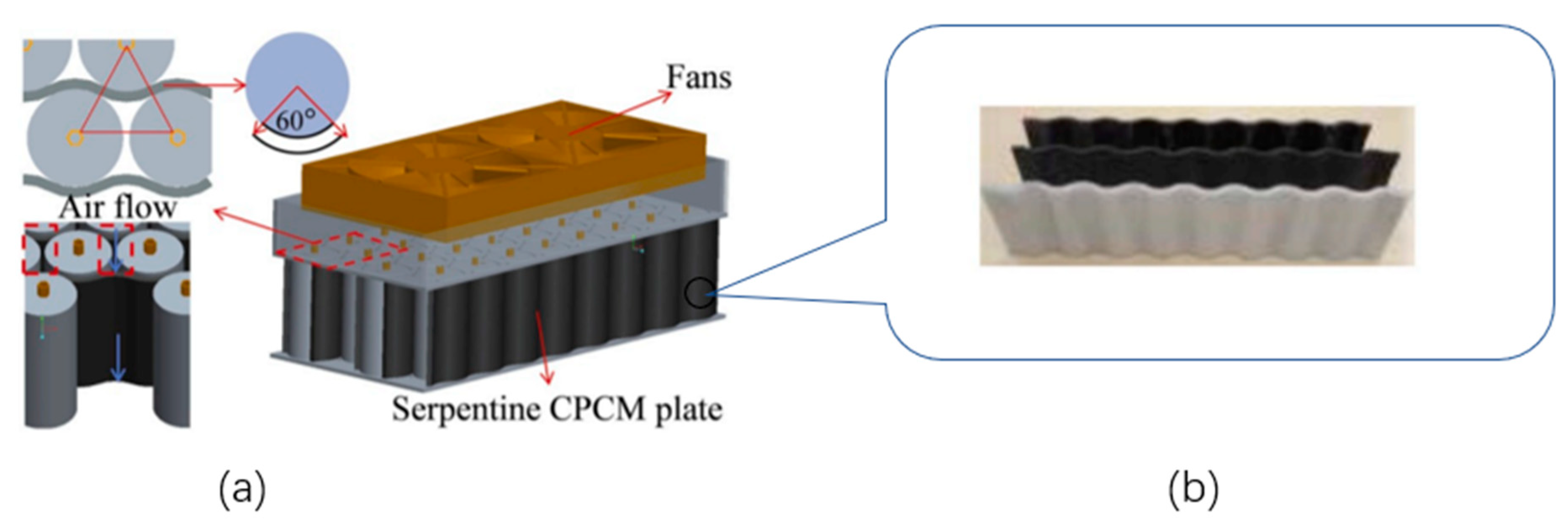
- Lv, Y.; Liu, G.; Zhang, G.; Yang, X. A novel thermal management structure using serpentine phase change material coupled with forced air convection for cylindrical battery modules. J. Power Sources 2020, 468, 228398. [Google Scholar] [CrossRef]
- Li, X.; He, F.; Zhang, G.; Huang, Q.; Zhou, D. Experiment and simulation for pouch battery with silica cooling plates and copper mesh based air cooling thermal management system. Appl. Therm. Eng. 2019, 146, 866–880. [Google Scholar] [CrossRef]
- Luo, W.; He, F.; Huang, Q.; Li, X.; Zhang, G.; Zhong, Z. Experimental investigation on thermal performance of silica cooling plate-aluminate thermal plate-coupled forced convection-based pouch battery thermal management system. Int. J. Energy Res. 2019, 43, 7604–7613. [Google Scholar] [CrossRef]
- Bibin, C.; Vijayaram, M.; Suriya, V.; Ganesh, R.S.; Soundarraj, S. A review on thermal issues in Li-ion battery and recent advancements in battery thermal management system. Mater. Today Proc. 2020, 33, 116–128. [Google Scholar] [CrossRef]
- Deng, Y.; Feng, C.; Jiaqiang, E.; Zhu, H.; Chen, J.; Wen, M.; Yin, H. Effects of different coolants and cooling strategies on the cooling performance of the power lithium ion battery system: A review. Appl. Therm. Eng. 2018, 142, 10–29. [Google Scholar] [CrossRef]
- Bamdezh, M.A.; Molaeimanesh, G.R.; Zanganeh, S. Role of foam anisotropy used in the phase-change composite material for the hybrid thermal management system of lithium-ion battery. J. Energy Storage 2020, 32, 101778. [Google Scholar] [CrossRef]
- Rao, Z.; Wang, Q.; Huang, C. Investigation of the thermal performance of phase change material/mini-channel coupled battery thermal management system. Appl. Energy 2016, 164, 659–669. [Google Scholar] [CrossRef]
- Ping, P.; Zhang, Y.; Kong, D.; Du, J. Investigation on battery thermal management system combining phase changed material and liquid cooling considering non-uniform heat generation of battery. J. Energy Storage 2021, 36, 102448. [Google Scholar] [CrossRef]
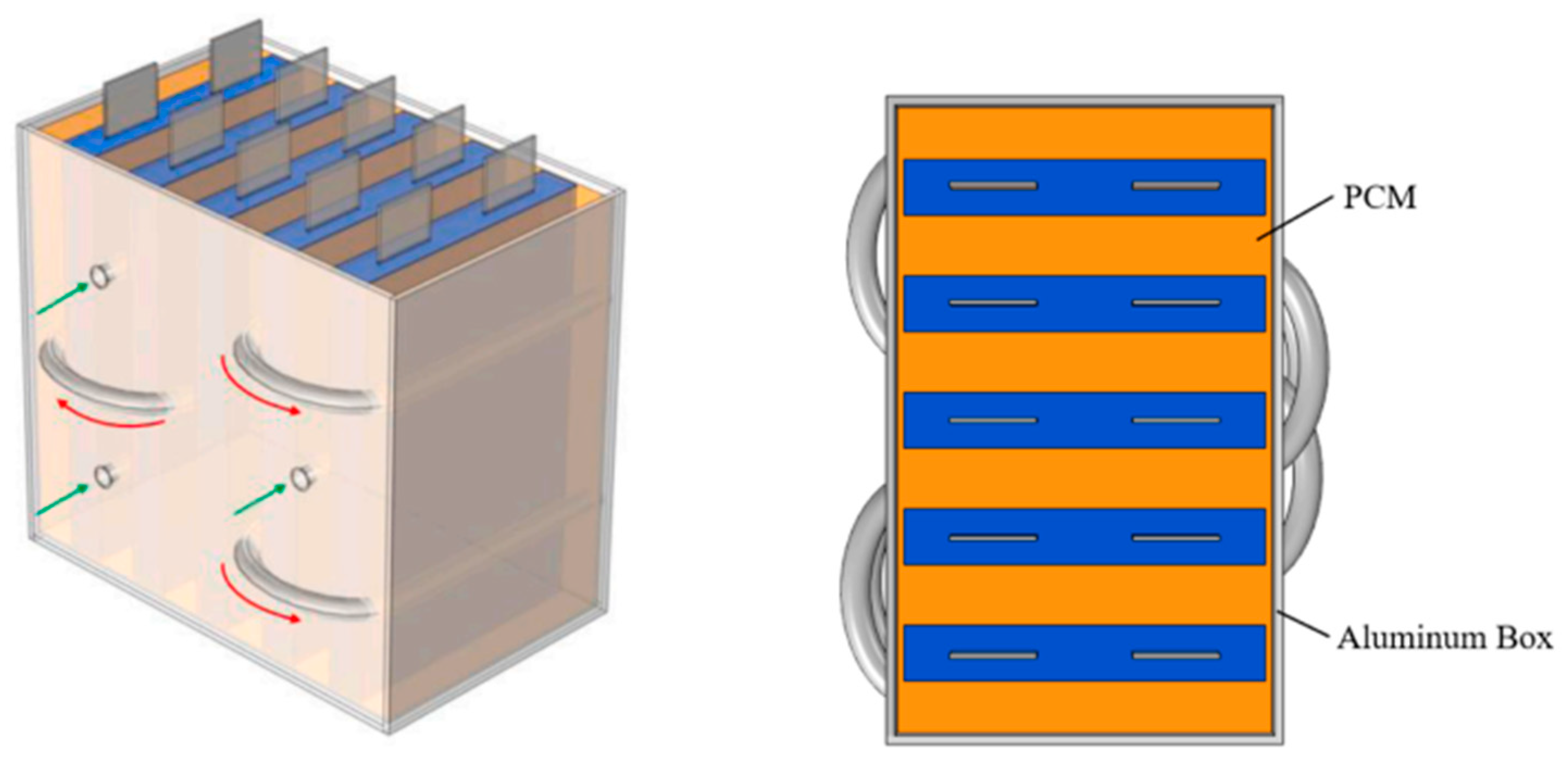
- Kong, D.; Peng, R.; Ping, P.; Du, J.; Chen, G.; Wen, J. A novel battery thermal management system coupling with PCM and optimized controllable liquid cooling for different ambient temperatures. Energy Convers. Manag. 2020, 204, 112280. [Google Scholar] [CrossRef]
- Liu, Z.; Huang, J.; Cao, M.; Jiang, G.; Yan, Q.; Hu, J. Experimental study on the thermal management of batteries based on the coupling of composite phase change materials and liquid cooling. Appl. Therm. Eng. 2021, 185, 116415. [Google Scholar] [CrossRef]
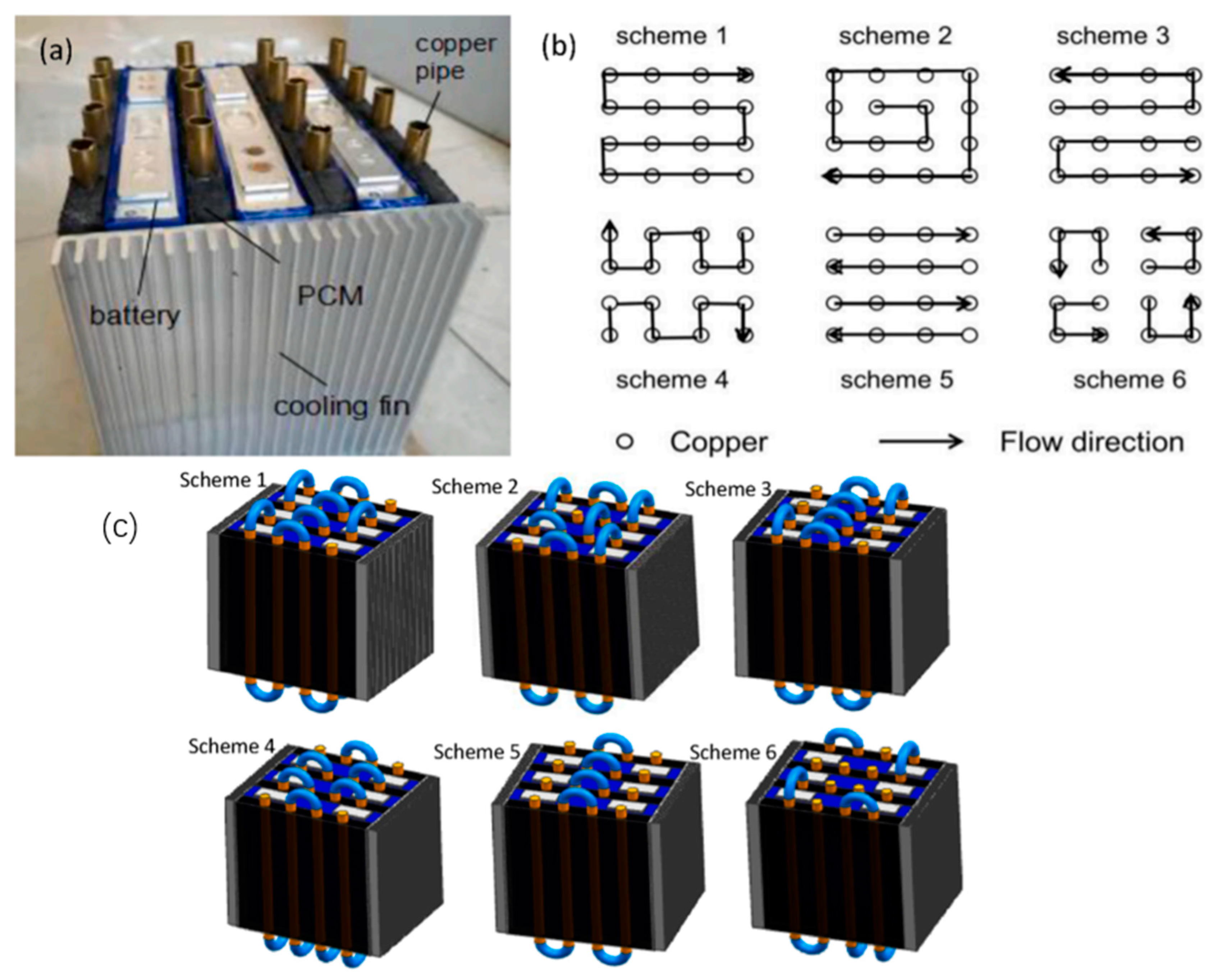
- Liu, H.; Ahmad, S.; Shi, Y.; Zhao, J. A parametric study of a hybrid battery thermal management system that couples PCM/copper foam composite with helical liquid channel cooling. Energy 2021, 231, 120869. [Google Scholar] [CrossRef]
- Xu, Y.; Li, X.; Liu, X.; Wang, Y.; Wu, X.; Zhou, D. Experiment investigation on a novel composite silica gel plate coupled with liquid-cooling system for square battery thermal management. Appl. Therm. Eng. 2021, 184, 116217. [Google Scholar] [CrossRef]
- Xu, X.; Tang, W.; Fu, J.; Li, R.; Sun, X. Plate flat heat pipe and liquid-cooled coupled multistage heat dissipation system of Li-ion battery. Int. J. Energy Res. 2019, 43, 1133–1141. [Google Scholar] [CrossRef]
- Ali, H.M. Applications of combined/hybrid use of heat pipe and phase change materials in energy storage and cooling systems: A recent review. J. Energy Storage 2019, 26, 100986. [Google Scholar] [CrossRef]
- Jouhara, H.; Serey, N.; Khordehgah, N.; Bennett, R.; Almahmoud, S.; Lester, S.P. Investigation, development and experimental analyses of a heat pipe based battery thermal management system. Int. J. Thermofluids 2020, 1, 100004. [Google Scholar] [CrossRef]
- Zhang, Z.; Wei, K. Experimental and numerical study of a passive thermal management system using flat heat pipes for lithium-ion batteries. Appl. Therm. Eng. 2020, 166, 114660. [Google Scholar] [CrossRef]
- Zhao, J.; Lv, P.; Rao, Z. Experimental study on the thermal management performance of phase change material coupled with heat pipe for cylindrical power battery pack. Exp. Therm. Fluid Sci. 2017, 82, 182–188. [Google Scholar] [CrossRef]
- Wang, Q.; Rao, Z.; Huo, Y.; Wang, S. Thermal performance of phase change material/oscillating heat pipe-based battery thermal management system. Int. J. Therm. Sci. 2016, 102, 9–16. [Google Scholar] [CrossRef]
- Zhao, J.; Rao, Z.; Liu, C.; Li, Y. Experiment study of oscillating heat pipe and phase change materials coupled for thermal energy storage and thermal management. Int. J. Heat Mass Transf. 2016, 99, 252–260. [Google Scholar] [CrossRef]
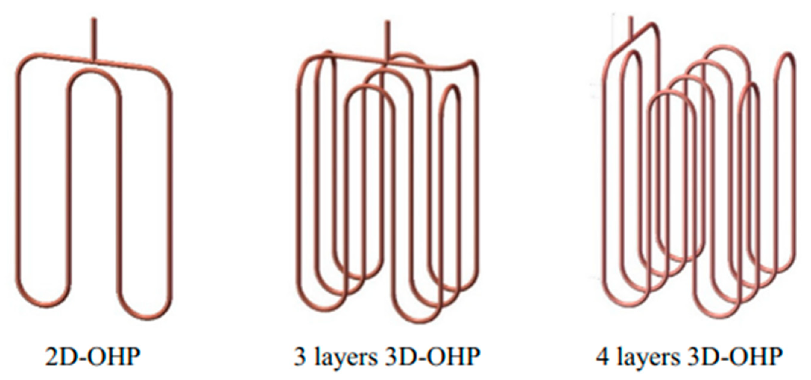
- Qu, J.; Ke, Z.; Zuo, A.; Rao, Z. Experimental investigation on thermal performance of phase change material coupled with three-dimensional oscillating heat pipe (PCM/3D-OHP) for thermal management application. Int. J. Heat Mass Transf. 2019, 129, 773–782. [Google Scholar] [CrossRef]
- Yuan, Q.; Xu, X.; Tong, G.; Ding, H. Effect of coupling phase change materials and heat pipe on performance enhancement of Li-ion battery thermal management system. Int. J. Energy Res. 2021, 45, 5399–5411. [Google Scholar] [CrossRef]
- Jin, X.; Duan, X.; Jiang, W.; Wang, Y.; Zou, Y.; Lei, W.; Sun, L.; Ma, Z. Structural design of a composite board/heat pipe based on the coupled electro-chemical-thermal model in battery thermal management system. Energy 2021, 216, 119234. [Google Scholar] [CrossRef]
- Yuan, X.; Tang, A.; Shan, C.; Liu, Z.; Li, J. Experimental investigation on thermal performance of a battery liquid cooling structure coupled with heat pipe. J. Energy Storage 2020, 32, 101984. [Google Scholar] [CrossRef]
- Behi, H.; Kalogiannis, T.; Suresh Patil, M.; Mierlo, J.V.; Berecibar, M. A new concept of air cooling and heat pipe for electric vehicles in fast discharging. Energies 2021, 14, 6477. [Google Scholar] [CrossRef]
- Zhong, G.; Zhang, G.; Yang, X.; Li, X.; Wang, Z.; Yang, C.; Yang, C.; Gao, G. Researches of composite phase change material cooling/resistance wire preheating coupling system of a designed 18650-type battery module. Appl. Therm. Eng. 2017, 127, 176–183. [Google Scholar] [CrossRef]
- Cao, J.; Feng, J.; Fang, X.; Ling, Z.; Zhang, Z. A delayed cooling system coupling composite phase change material and nano phase change material emulsion. Appl. Therm. Eng. 2021, 191, 116888. [Google Scholar] [CrossRef]
- Lv, Y.; Yang, X.; Li, X.; Zhang, G.; Wang, Z.; Yang, C. Experimental study on a novel battery thermal management technology based on low density polyethylene-enhanced composite phase change materials coupled with low fins. Appl. Energy 2016, 178, 376–382. [Google Scholar] [CrossRef]
- He, F.; Li, X.; Zhang, G.; Zhong, G.; He, J. Experimental investigation of thermal management system for lithium ion batteries module with coupling effect by heat sheets and phase change materials. Int. J. Energy Res. 2018, 42, 3279–3288. [Google Scholar] [CrossRef]


| Serial Number | Cooling System | Advantage | Shortcoming |
|---|---|---|---|
| 1 | Air cooling system | Simple structure, low cost, small footprint, lightweight, etc. | Low thermal conductivity, poor cell uniformity control, etc. |
| 2 | Liquid cooling system | Good thermal conductivity, good cooling effect, relatively uniform heat dissipation, etc. | There is a risk of liquid leakage, difficult maintenance, heavyweight, complex structure, etc. |
| 3 | Phase-change material cooling system | High heat density, large latent heat, good stability, fast heat dissipation, high-temperature control uniformity, etc. | The heat absorbed by the phase change material cannot be well dissipated to the external environment, etc. |
| 4 | Heat pipe cooling system | High thermal conductivity, high heat dissipation efficiency, fast heating rate, good uniform performance, good safety, high reliability, etc. | High cost, difficult to control the amount of heat exchange medium, complicated structure, inconvenient installation, etc. |
| Serial Number | Internal Heating | Advantage | Shortcoming | Temperature Rise Rate (°C/s) |
|---|---|---|---|---|
| 1 | Self-heating | High heating efficiency, no additional equipment required | It is necessary to change the existing battery structure and existing battery production process, which has certain safety risks | 0.46 [52] |
| 2 | AC heating | Higher heating efficiency and better cell temperature consistency | Low-frequency alternating current has great damage to the battery, and the system control is complicated | 0.063 [54] |
| 3 | Pulse current heating | Cell temperature consistency is good | Complex system control, high cost, and high energy consumption | 0.025 [57] |
| Serial Number | External Heating | Advantage | Shortcoming | ΔT/°C |
|---|---|---|---|---|
| 1 | Hot air heating | Simple structure, low cost, and easy control | Large space and low heating efficiency | ≤5 |
| 2 | Liquid heating | High heating efficiency and good cell uniformity | High tightness requirements and high costs | ≤5 |
| 3 | Phase-change material heating | Simple structure, small footprint, low energy consumption, good battery temperature uniformity | Relatively immature process, high thermal conductivity, and high cost | ≤5 |
| 4 | Electric heating element heating | Simple structure, small footprint, and high heating efficiency | Less secure | ≤5 |
| 5 | Peltier effect heating | High heating efficiency and high battery temperature control accuracy | High cost, complex structure, and immature process | ≤8 |
Publisher’s Note: MDPI stays neutral with regard to jurisdictional claims in published maps and institutional affiliations. |
© 2022 by the authors. Licensee MDPI, Basel, Switzerland. This article is an open access article distributed under the terms and conditions of the Creative Commons Attribution (CC BY) license (https://creativecommons.org/licenses/by/4.0/).
Share and Cite
Wang, X.; Liu, S.; Zhang, Y.; Lv, S.; Ni, H.; Deng, Y.; Yuan, Y. A Review of the Power Battery Thermal Management System with Different Cooling, Heating and Coupling System. Energies 2022, 15, 1963. https://doi.org/10.3390/en15061963
Wang X, Liu S, Zhang Y, Lv S, Ni H, Deng Y, Yuan Y. A Review of the Power Battery Thermal Management System with Different Cooling, Heating and Coupling System. Energies. 2022; 15(6):1963. https://doi.org/10.3390/en15061963
Chicago/Turabian StyleWang, Xingxing, Shengren Liu, Yujie Zhang, Shuaishuai Lv, Hongjun Ni, Yelin Deng, and Yinnan Yuan. 2022. "A Review of the Power Battery Thermal Management System with Different Cooling, Heating and Coupling System" Energies 15, no. 6: 1963. https://doi.org/10.3390/en15061963
APA StyleWang, X., Liu, S., Zhang, Y., Lv, S., Ni, H., Deng, Y., & Yuan, Y. (2022). A Review of the Power Battery Thermal Management System with Different Cooling, Heating and Coupling System. Energies, 15(6), 1963. https://doi.org/10.3390/en15061963