Article

Comparative Analysis of Hybrid Electric Architectures for Specialized Agricultural Tractors

Department of Mechanical and Aerospace Engineering, Politecnico di Torino, Corso Duca degli Abruzzi 24, 10129 Torino, Italy
*
Author to whom correspondence should be addressed.
Energies 2022, 15(5), 1944; https://doi.org/10.3390/en15051944
Submission received: 10 February 2022 / Revised: 2 March 2022 / Accepted: 3 March 2022 / Published: 7 March 2022
(This article belongs to the Special Issue Frontiers in Hybrid Vehicles)

Abstract

:
In this work, a comparative numerical analysis between the performance of a conventional specialized orchard tractor and those of three different hybrid electric tractor configurations is presented. The aim was to compare several powertrain configurations in the same working scenarios derived from field measurements. Peak power capabilities and endurance were numerically tested with specific load scenarios involving both transportation mission profiles and field activities with external implements powered through the power take off of the tractor. The proposed hybrid architectures were configured with the same battery-based energy storage system to perform the comparison with the same energy storage capabilities. Two parallel, two series and one electro-hydraulic hybrid configuration were modeled and tested through simulations. The parallel ones excelled in peak power performance, whereas the series configurations had the highest fuel savings. The electro-hydraulic configuration was proposed as an alternative able to allow for a downsized engine but also for the introduction of the Continuously Variable Transmission (CVT) functionality, which is always an interesting feature for such working machines.

1. Introduction

Agriculture has always played a crucial role when it comes to food for human beings. With the current population growth, the need for a highly productive agriculture has become mandatory. In this direction, agriculture automation and mechanization have proven to increase farms productivity [1]. However, with productivity comes a high impact on the environment. In particular, cultivation agriculture alone can be seen as responsible for almost 20% of the annual global production of CO2 emissions [2]. Other harmful products, such as NOx and particulate matter, are the undesired effects of all the heavy-duty agricultural machinery propelled by high-power diesel engines to perform their daily activities [3]. For this reason, strict emission regulations have been progressively imposed all around the world to mitigate, in general, pollutant emissions of non-road mobile machinery (NRMM) [4].
To be compliant with these regulations, several techniques have been proposed by OEM diesel engines manufacturers [5]. Exhaust gas recirculation (EGR) systems aim to reduce the amount of NOx emissions recirculating in the combustion chamber part of the exhaust stream to reduce the average combustion temperature. However, to produce the same amount of power, a higher fuel rate should be provided; thus, overall lower efficiency of the system can be expected. Diesel particulate filter (DPF) systems remove particulate matter of a certain grain size from the exhaust gases, but periodic fuel burning procedures are required to clean the filter. Selective catalytic reduction (SCR) systems introduce molecular ammonia into the exhaust stream to lower the amount of NOx. However, despite the higher efficiency of these systems, the vehicle should be provided with a dedicated tank to store urea solutions to be used while working. Overall, those systems proposed at the OEM level do not completely solve the problem and put vehicle manufacturers in difficulties when it comes to onboard integration. However, agricultural tractors and in particular specialized tractors, are well known for the compactness of their powertrains, which is required for visibility, maneuverability [6] and in general to reduce the overall weight which can cause excessive soil compaction. For these reasons, new technologies have been explored by researchers and manufacturers to reduce pollutant emissions, increasing the overall efficiency of the vehicle.
On that topic, tractor powertrain electrification is one of the most promising strategies that will gain visibility in the upcoming years [7]. As suggested by Somà et al. [8], electrification of a heavy-duty working vehicle should always be performed with a proper hybridization factor (HF) between the thermal engine and the electric machines. The HF value for a working vehicle should come from the statistical investigation on the average use of the specific machine to avoid improper adoption of oversized components, which would affect the overall functionality and cost of the machine [9]. Actually, a good design based on the working cycle of the machine can allow the use of full electric architectures (with HF = 1), thereby avoiding the use of an internal combustion Engine (ICE) as the primary power source in favor of a properly designed battery-based energy storage system (BESS) [10].
Electric and hybrid topologies for agricultural tractors are becoming more and more interesting for industrial manufacturers, who are proposing concepts of their vehicles at fairs almost all around the world [11], and they are receiving good feedback by experts of the field. However, the application of this technology on these working machines is still at its early stage, as demonstrated by the absence of commercially available products. The scientific community is demonstrating more and more interest on this topic due to the intrinsic peculiarities of agricultural tractors when compared with other working vehicles. Several studies are available in the literature exploring the performances of specific hybrid electric architectures. Particular attention is given to full electric tractor (FET) configurations, where the entire vehicle is powered by a properly sized BESS, as a viable solution for farm decarbonization [12]. Liu et al. [13] explored the overall energy conversion efficiency of a FET when using a load torque-based control strategy to optimize motor performance for a given gearbox transmission. Vogt and Melo et al. [14,15] proposed a small FET for family farming applications. Their idea was to propose a tractor with a 9 kW electric motor propelled by a low voltage battery pack, able to perform most of the simplest tasks which need to be performed in a small farm with a low cost tool. To optimize the typical working ranges of a tractor, Li et al. [16] proposed a FET architecture where two electric motors with different electro-magnetic characteristics are coupled together to have full torque at low rpm and the best efficiency at higher speed ranges. This is an interesting idea, but requires a higher number of components, and thus a lot of space, which goes against the simplicity of a FET architecture.
Although FETs represent a great solution for manufacturers due to the lower number of components involved in comparison with diesel powered traditional tractors, the actual state of the art of BESSs prevents their widespread diffusion due to the limited amount of storable onboard energy. For this reason, several studies focused their attention on the design of and performance evaluations of hybrid electric tractor (HET) architectures. Dalboni et al. [17] proposed a study where an HET with parallel configuration was studied and built for experimental validation. In this work, the research group proposed a prototype with a downsized diesel engine coupled with an electric motor-generator powered by a 25 kWh BESS. The HET was tested on a field with a set of 12 working scenarios using a charge sustaining control strategy and showing good results in fuel savings. The experimental platform allowed them to demonstrate the unfeasibility of fully electric operation due to the limited energy storage. This vehicle did good results in hybrid mode in all the proposed scenarios though. A similar parallel HET configuration was studied numerically by Mocera and Somà [18]. They tested a traditional model and a hybrid electric model against test cases derived experimentally from a real orchard tractor. The proposed working scenarios involved both transportation with trailer and field operations with several types of implements attached to the machine. An average energy saving of 17% was obtained by the proposed architecture using a load observer control strategy, which was then tested by Mocera [19] on a real hardware platform in a hardware-in-the-loop (HIL) test bench configuration. Several studies are also available in the literature on series HET architectures. Baek et al. [20,21] proposed a study based on a prototype of an all-wheel drive tractor where four dedicated motors were connected to the wheels with specific gearboxes. In this case, the tractor was of a high-power class with an installed power greater than 120 kW obtained by the cooperation of a battery pack and four gasoline-based commercial generators. The proposed configuration showed good peak torque capabilities but with a workable time of 2.5 h in plow tillage. Thus, in this case too, the size of the battery pack represented a critical point to be addressed. More complex architecture have been investigated in the literature to couple the advantage of series and parallel configuration characteristics. Rossi et al. [22,23] proposed a hybrid electric CVT configuration, in which the use of a planetary gearbox increased the efficiency of every operating mode for all the involved power sources. In this way, it was possible to consider the best power flow depending on the specific working conditions the tractor was requested to face. Mocera et al. [24] investigated a hybrid electric CVT (HeCVT) configuration for an orchard tractor, highlighting energy efficiency improvements ranging from 10% in the most power demanding tasks to 20% for transportation of heavy trailers where the added degrees of freedom helped with the optimal ICE control.
Thus, studies on several HET architectures are available in the literature, but to the authors’ knowledge, there is still no clear answer on which architecture best fits a specific tractor class. In this work, the authors proposed three different HET topologies, whose performances were tested against those of a traditional orchard tractor. To achieve this, the same working scenarios were applied to all the proposed models to perform a one-to-one comparison in terms of peak power capabilities. Moreover, given a certain type of battery pack configuration, all the HET solutions were tested against some representative daily working cycles. Interesting results were obtained in terms of efficiency improvements, although the performances of some of the proposed topologies were more affected than others by the BESS size.

2. Materials and Methods

2.1. Case Study Description

Orchard tractors are specialized tractors that are designed to operate among narrow rows. Compactness for this class of agricultural machines is crucial to increase productivity in such small working spaces. The vehicle’s wheelbase and track width can strongly affect its curving capabilities, regarding its range of approachable orchards. The characteristics of the conventional diesel-powered orchard tractor (CDOT) studied in this work are shown in Table 1.
Due to the wide range of workloads these machines may encounter during their lives, it is a common practice and a customer request to have tractors equipped with high power diesel units. However, looking at the most common working scenarios and at their distribution throughout the year, the engine designed to accomplish heavy duty tasks is mostly used at medium–low loads. Consequently, the resulting efficiency is not optimal, and it translates into fuel wastage with respect to the real daily energy needs. As shown in Figure 1, a numerical model of the following subsystem was developed using Matlab/Simulink version 2021b to simulate tractor performance:
  • Engine
  • Gearbox and clutches
  • Longitudinal dynamics
  • Power Take Off (PTO) loads.
The engine was modeled using a tabulated torque data approach, so that the speed–torque and speed–power curves shown in Figure 2 represent the maximum torque and power output at full throttle. The proposed torque and power curves were derived from data available online for commercial diesel engine units having nominal characteristics as close as possible to the ones of the reference conventional tractor studied in this and previous works by the authors. To make a comparison between the proposed HET powertrains, a parametric fuel consumption estimation model was used. In this work, the model proposed by the Nebraska Tractor Test Laboratory, proposed also by Grisso et al. [25], was calibrated and used according to the following equations:
Q F = ( 0.0434· X + 0.019) · P n o m 0.735 · 3.785
Q R = Q F · 1 ( N 1 ) · ( 0.45· X 0.877)
where:
  • Q F is the diesel fuel consumption at partial load and full throttle (L/h);
  • Q R is the diesel fuel consumption at partial load and reduced throttle (L/h);
  • X is the actual engine load expressed as the ratio of the actual engine output power over the maximum power available at the same speed (−);
  • P n o m is the nominal engine power (kW);
  • N is the ratio between the actual engine speed and the nominal speed at which P n o m is evaluated.
The proposed fuel consumption model was tested by the authors with respect to several tractor tests performed by the Nebraska Tractor Laboratory. On this population, this approximated model achieved average errors between the estimated fuel consumption and the actual consumption of around 10%. However, in this work the proposed model did not need to provide the exact value of fuel consumption (which would require experimental validation), but was a tool to compare fuel consumption between engines of different nominal power, different load characteristics and different operating speeds. These are the most relevant quantities affecting fuel consumption in diesel engines.
Figure 2. Torque and power characteristics for the diesel engine of the conventional tractor.
Energies 15 01944 g002
Tractors are well known for their very complex transmission gearboxes whose aim are to distribute the engine power as well as possible from very-low-speed field operations up to the maximum speed used for road transportation. The gearbox in this work was modeled using groups of simple gears connected in series or in parallel with the help of disengaging friction clutches to achieve the overall desired vehicular speed.
The longitudinal dynamic behavior of the tractor was modeled according to the approach proposed by the authors in previous works [18], using a 1D model as shown in Figure 3. The 1D model considers the vehicle longitudinal motion as a result of all the relevant forces and torques applied on the tractor body. Propulsion comes from the overall longitudinal force derived from the interaction between the wheels and the ground, and the resistive contribution mainly comes from rolling resistance (wheel–ground interaction), weight in cases of inclined surfaces and all the forces transmitted from the attached trailer to the tractor. Although included in the vehicle model, the resistive contributions of the aerodynamic forces are negligible with respect to the other ones.
As for the interaction between the wheels and the soil, the tire friction was parametrized in terms of static and kinetic coefficients. The static friction coefficient determines the applied torque at which the tire loses traction and begins to slip, and the kinetic friction coefficient determines the amount of torque the tire transmits to the pavement once it begins to slip.
m V x ˙ = 2 F x f + F x r F d m g · s i n β
F z f = h F d + m g · s i n β + b · m g · c o s β 2 ( a + b )
F z r = + h F d + m g · s i n β + a · m g · c o s β 2 ( a + b )
where:
  • a, b, and h represent the relative position of the centre of gravity of the vehicle with respect to the front and rear axles;
  • m is the tractor mass, g the acceleration of gravity;
  • β is the road slope angle;
  • V x is the vehicle longitudinal speed;
  • F d is the aerodynamic drag force as F d = 0.5ρ C d A V x 2 · s i g n ( V x ) , ρ is air density, C d is the drag coefficient and A is frontal cross-sectional area of the vehicle;
  • F x f and F x r are the contact forces between the wheels and the ground on the longitudinal direction (front and rear axle);
  • F z f and F z r are the normal contact forces between the wheels and the ground (front and rear axle).
To simulate the presence of a trailer attached to the tractor, a rigid connection was considered between the two bodies to share the same longitudinal speed. Thus, the overall system accelerates by way of the global mass and the balance between the tractive force developed by the drivetrain and the overall resistive contributions, including those acting on the trailer. Different payloads on the trailer were simulated changing accordingly its mass. Finally, the power take off of the tractor, and any attached implements, was modeled. In general, all the implements considered in this study were modeled as resistive torques applied to the tractor PTO to absorb certain amounts of power. From experimental data obtained in previous works [18], three implements’ loads were studied with their relevant characteristics when powered at a PTO speed of 540 rpm. These experimental data were collected from the CAN BUS network from a real orchard tractor, with characteristics very close to the ones of the conventional vehicle considered in this work, using a USB CAN analyzer. These data were then post-processed to derive, from the actual engine load and speed and the vehicle work speed, the power requested by the considered implements. In Figure 4, examples of measured data from field tests with a rotary harrow attached are reported. Table 2 shows a summary of these three working scenarios.
In this study, parametric models of the required power for the atomizer and harrowing activities are also proposed. These models were created and calibrated by the authors in accordance with the experimental data showed in Table 2. The main purpose of the proposed models was to replicate changes of the work activities’ characteristics in terms of required power when their main parameters changed. However, for the purpose of this work, these models were just calibrated according to the available data, but will be further investigated in future works. In terms of power consumption, the most relevant components within an atomizer are the hydraulic pump and the fan. Based on that, the following parametric model was proposed.
P a t o m i z e r = P p u m p + P f a n = Q p · p p η p + Q a i r · Δ p t η f
where
  • Q p is the pump flow.
  • p p is the pump pressure gain.
  • η p is the pump efficiency.
  • Q a i r is the fan air flow.
  • Δ p t is the total pressure difference through the fan, total pressure means static pressure plus dynamic pressure.
  • η f is the fan efficiency.
As for the rotary harrow, the proposed parametric model considered the implement’s working width, the depth of cut and the feed rate. The power required by the rotary harrow was defined by two elements: the power required by the PTO to activate the harrow, and the additional power required at the wheels to tow it. According to these considerations, the following equation was proposed:
P h a r r o w = P P T O + P w h e e l = K · p · B + K 1 · v f d · p · B 1
where
  • K is a coefficient of the power required at the PTO, expressed in W/(m2).
  • p is the depth of cut.
  • B is the effective working width.
  • K 1 is a coefficient of the additional power required at the wheels, expressed in N/(m2).
  • v f d is the feed rate.
  • B 1 the operative working width.
In Figure 5, it is possible to appreciate a schematic representation of the power flow within the driveline. The additional load deriving from an attached trailer will affect the portion of power flowing through the transmission to the wheels, affecting the overall acceleration performance of the vehicle.

2.2. HET Architectures under Investigation

In this work, three different types of HET architectures were considered, starting always with the same design goal to use a downsized diesel engine (Figure 6). The use of a smaller internal combustion engine was inspired by the following considerations:
  • Orchard tractors are usually equipped with oversized diesel engines, to meet occasional peaks in power demand. For large portions of their operational lives, they work with partial medium–low loads. Therefore, higher fuel consumption and lower overall efficiency are inevitable. A downsized engine would work at higher loads, which means better fuel management and higher efficiency.
  • NRMM regulations classify engines according to their nominal power. Thus, an oversized engine has stricter restrictions about the admissible amount of pollutant production than smaller ones which instead produce lower amounts of harmful emissions per kWh of mechanical energy produced. Consequently, vehicles in the lower power class need smaller and lighter exhaust gas after-treatment systems.
Figure 6. Downsized ICE torque and power curves.
Energies 15 01944 g006
In the proposed HET architectures, electric motors were design to support the thermal unit when power peaks were required. However, along with the electric drives, a proper control strategy and BESS should be considered. The BESS considered for this work was the same for all three different HET configurations in order to provide the same storage for all the proposed working scenarios and cycles. The proposed BESS has the characteristics shown in Table 3.
Given them, to monitor the actual state of charge of the battery pack, a simple Coulomb counting strategy was used in this work, neglecting more detailed model available in the literature [26]. The following equations were used:
C u s e d = t 1 t 2 i b a t t d t
S O C = C n o m C u s e d C n o m
where:
  • C u s e d is the used capacity;
  • C n o m is the nominal capacity;
  • S O C is the state of charge of the battery pack.

2.2.1. Parallel HET

This configuration was characterized by the implementation of the electric unit mechanically coupled in parallel with respect to the thermal engine, so that either the ICE or the EM could individually drive the tractor wheels (Figure 7). The two power sources were linked upstream of the transmission. The interesting point about this solution is that it aims to use the same gearbox as the conventional powertrain. For this parallel HET architecture, two different electric motors were proposed, whose properties are shown in Table 4.
The EMs adopted were reversible machines, so they could act as generators when needed. This is an important requirement because, together with the power converter characteristics, it allowed the tractor to recover energy during operations, and eventually charge the battery pack when idling. The electric machines and power converters were simulated as a function of a speed-torque data curve which defines the limit capabilities of the electric unit. Figure 8 shows the typical torque–speed and power–speed profiles of the EMs considered in this work. The numerical model of the electric machines considered the electrical losses as the sum of the following terms: fixed converter losses, ohmic losses (torque dependent) in copper windings and iron losses (speed dependent) due to eddy currents. In this way, the mechanical power available at the motor shaft was linked to the electrical power interacting with the high-voltage DC bus. If the electric machine was actuated to provide mechanical power, the current taken from the DC Bus was a function of the motor current (thus torque) and actual speed. On the other hand, if the electric machine acted as generator, the current was supplied to the high-voltage DC bus and modulated according to the actuation signal (limiting the braking torque). However, this is a simplified approach that the authors considered sufficient for the analysis conducted in this work. Future works might include a more detailed model of the electric machines. The electrical power requested by the electronic drive was fed by the electric capabilities of the battery pack.

2.2.2. Series HET

The series HET configuration was characterized by the implementation of two electrical units, a generator and an electric motor (Figure 9). The thermal unit is not kinematically linked to the wheels, so it is possible to let it work in its optimal point, and turns the generator, while the vehicle is driven by the electric motor. Both electrical units considered in this work were reversible machine. On the other hand, the PTO was mechanically linked to the ICE and the generator. This connection still represents a constraint for the optimal operation of the diesel engine as also discussed by Varani et al. [27].
There might be several advantages in electrically driven external implements both in terms of efficiency and controllability. However, due to the higher complexity in terms of onboard integration when it comes to add new electric components, for the purpose of this work the authors preferred to not consider this other type of series HET configuration. The electric motor is connected to the wheels through a two-speed gearbox: one dedicated to high-speed road transportation (maximum speed 40 km/h) and one for low speed-high torque operations (maximum speed 12 km/h). Additionally, in this case, two different solutions were proposed, differentiated by the EM characteristics, whose properties are shown in Table 5.

2.2.3. Electro-Hydraulic HET

The electro-hydraulic HET architecture had one thermal unit and one electric motor, coupled in parallel upstream of the driveline (Figure 10). The transmission was characterized by the implementation of a hydraulic circuit, including a variable displacement hydraulic pump and a hydraulic motor. The ICE and the EM turned the hydraulic pump; therefore, the pump converted mechanical power into a hydraulic high-pressure flow, while the hydraulic motor converted it back into mechanical power available at the output shaft. This HET configuration allowed for decoupling of the engine from the wheels, and thus, for a Continuously Variable Transmission (CVT).
From the functional point of view, this solution wanted to mimic the benefits of the more traditional series HET architecture, but with the goal of using just one electric machine to help the downsized engine as in the parallel HET. As for the series HET architecture, this electro-hydraulic HET needed a gearbox with two speed ranges for the low torque–high speed and high torque–low speed working scenarios. The main properties of the electro-hydraulic powertrain considered in this work are shown in Table 6.
To limit the maximum pressure in the hydraulic circuit, a pressure relief valve was needed at the model level, and the pressure drop at which the valve began to open was set at 300 bar. The hydraulic system was modeled considering a variable-displacement pump and a variable-displacement motor for the grater flexibility in controlling its operating working conditions. However, for the purposes of the specific tests performed in this work, the motor displacement was considered fixed at a constant value during simulations. The parameters were set so that the efficiency curves of the pump and the hydraulic motor, obtained at 1500 rpm, fluid temperature 50 °C and kinematic viscosity of 30 mm2/s, were equal to those reported in Figure 11.

2.3. Control Strategies for HET Architectures

The proposed HET architectures have different characteristics in terms of number and performance of the installed electric machines, but also in interaction with the ICE, which represents the most abundant energy source, crucial for long field activities. Thus, different control strategies were required to properly manage the power units. The authors always kept in mind the primary goal for a machine: being able to complete an assigned task. To be able to increase the overall efficiency of the powertrain and complete the tasks, it is important to carefully use the amount of electric energy in the BESS. From the system point of view, this component and its power flow needs to have the highest level of attention due to the time required to refill this energy reservoir. Thus, looking at Figure 12 the energy management strategy adopted for all the HET architectures can be described as follows (see Gao et al. [28] and Zhang and Zhang [29]):
  • For S O C > 30 % , the powertrain operated in charge depleting (CD) mode;
  • For S O C 30 % , the powertrain operated in charge sustaining (CS) mode.
Figure 12. SOC management strategy.
Energies 15 01944 g012
The SOC threshold at 30% was identified as a first reference value in order to imagine a safe working scenario for the BESS batteries. This value can be further optimized with a deeper knowledge of the working scenarios as well of the specific chemistry adopted. This will be further discussed in future works.

2.3.1. Parallel HET Control Strategy

In CD mode, the Parallel HET control strategy was based on the continuous monitoring of the ICE load. The control signal of the electric motor was weighted by a function of the actual engine load. The engine load was defined as the ratio between the actual power output and the maximum power of the engine for a given rotational speed. The aim of the strategy was to use the thermal unit as much as possible, and the main role of the electric motor was to help it during peaks in power demand. As a consequence, there was a relevant level of electric motor boost only above a certain level of power demand according to the load observer approach proposed by Mocera and Somà [18]. In CS mode, the aim of the strategy was to maintain the BESS SOC around 30% actuating the electric machine as a generator. Figure 13 shows a schematic representation of the control strategy.

2.3.2. Electro-Hydraulic HET Control Strategy

The control strategy used for the electro-hydraulic HET architecture was the same one used for the parallel HET, shown in Figure 13. This was mainly due to the fact that for this architecture the ICE and the EM were arranged in parallel, upstream the hydraulic transmission. During the proposed tests, the ICE rotational speed was maintained at a fixed value and the vehicle speed was regulated changing the displacement of the hydraulic pump. Increasing the pump displacement means increasing the vehicle speed. The law of variation of the pump displacement was optimized for each test.

2.3.3. Series HET Control Strategy

As for the electric motor, it was controlled by the vehicle’s speed requests. Instead, a control strategy based on the two modes, CD and CS, was designed for the generator. In CD mode, the generator was controlled according to the selected speed (low–high). The main difference between the modes was that for the low-speed range the generator supported the ICE, whereas for the high-speed range the generator was turned by the ICE, in order to provide energy to the electric motor. In the low-speed range, the control signal of the generator was weighted by a function of the actual engine load, so that the generator could support the ICE during peaks of power required by the PTO. This principle, used in the low-speed range, was the same load observer approach applied to the parallel and electric-hydraulic HET architectures, with the ICE used as much as possible and the generator that provided relevant power only when high levels of power were required by the PTO. In the high-speed range, the control signal of the generator was weighted by a function of the BESS current, so that it provided enough power to the EM to have a good level of autonomy in CD mode. In this case, the key parameter is the ratio between the actual BESS discharge current and its maximum allowed instantaneous discharge current, fixed at 5C. As for the CS mode, its purpose was to keep the battery pack SOC around 30% both in the low and high speed ranges. A schematic representation of the generator control strategy is shown in Figure 14.

3. Results

To make a comparison between the conventional powertrain and the proposed HET architectures, several tests were performed. Tests were designed to evaluate both peak power capabilities of the proposed powertrains and and energy demand for typical daily working scenarios. Acceleration and slope tests in transportation can give a good representation of peak capabilities, because all the power is directly used for a specific purpose: a quick acceleration or the maximum approachable slope. On the other hand, during field activities, the power produced might need to propel the vehicle in terms of tractive force and/or activate the attached implement. In these cases, the endurance of the power unit is of greater interest because peak capabilities may be involved only for very short periods, whereas the tractor must be able to last an entire working day. This is the reason of the section where considerations about two possible daily working scenarios are provided. Finally, since the BESS has the same characteristics in all the proposed HET architectures, some constraints were applied on its operational capabilities during tests to propose a hypothetical precautionary approach aimed to preserve its state of health (SOH):
  • Maximum battery pack current during continuous discharging equal to 3 C n o m .
  • Maximum battery pack current during instantaneous discharging equal to 5 C n o m (maximum 10 s).
  • Maximum battery pack current during continuous charging equal to 0.5 C n o m .
  • Maximum battery pack current during instantaneous charging equal to 1 C n o m .
These constraints were derived from the knowledge gained by the research group in previous numerical and experimental activities focused on the application of LiFePO4 cells within BESSs specifically designed to operate on hybrid electric working vehicles [10,30].
As for the interaction between the wheels and the soil, during the numerical simulations, the static and kinetic friction coefficients were changed according to the simulation’s needs. In particular, for the performance tests and trailer handling tests, the coefficients were set considering a paved road, whereas for the PTO tests they were set considering a field terrain.

3.1. Acceleration Performance

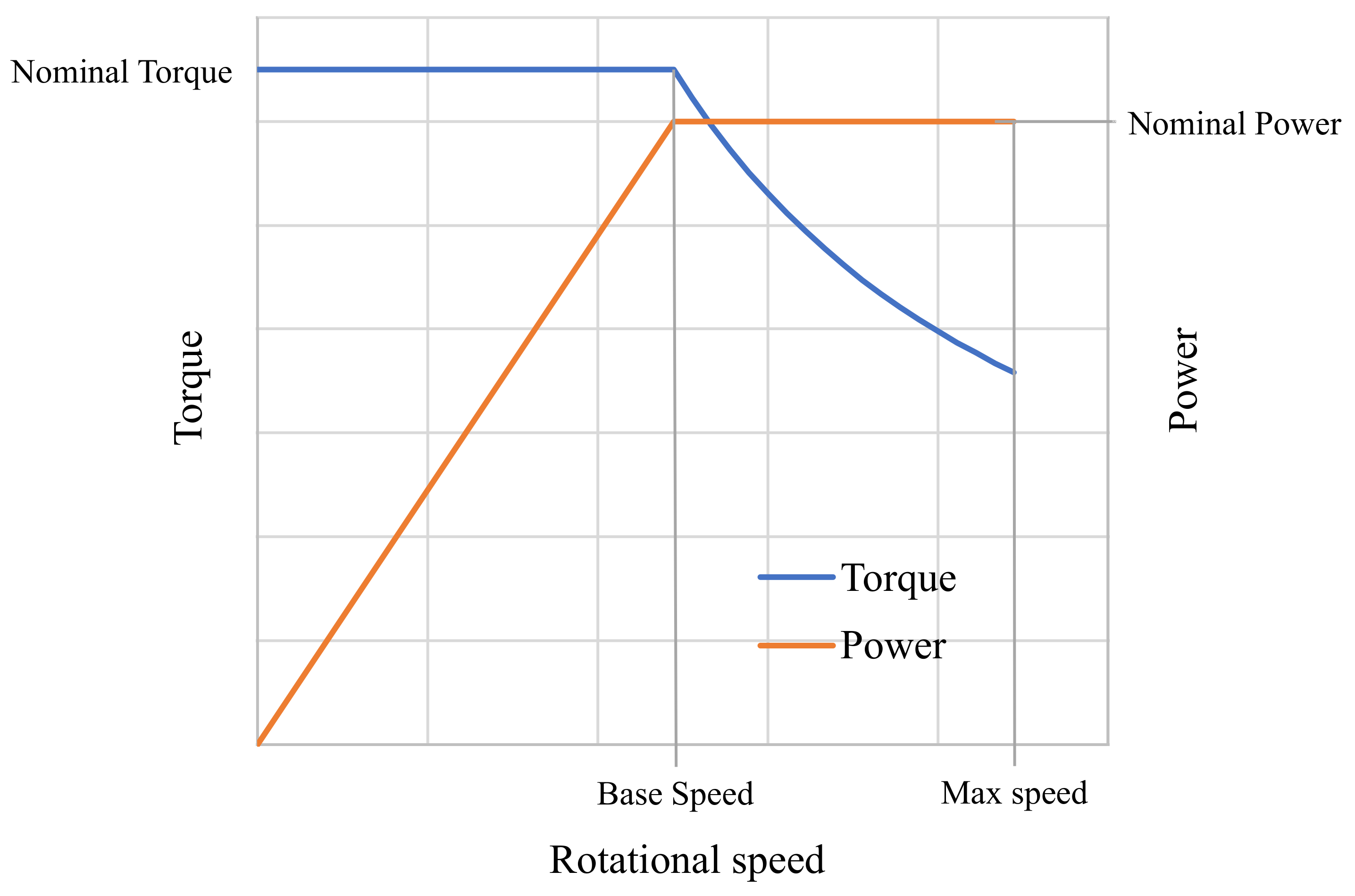
The proposed acceleration tests aimed to evaluate performance of the proposed HET architectures in the two macroscopic working speed ranges within which a traditional tractor may be required to operate. As stated before, these two ranges are characterized by a low maximum speed and high available torque (Low speed range), or by a high maximum travel speed and low torque (High speed range). For these reasons, the following acceleration tests were proposed for the numerical analysis:
  • 0–15 km/h with no trailer, with a trailer with 6000 kg and 10,000 kg of payloads.
  • 0–40 km/h with no trailer, with a trailer with 6000 kg and 10,000 kg of payloads.
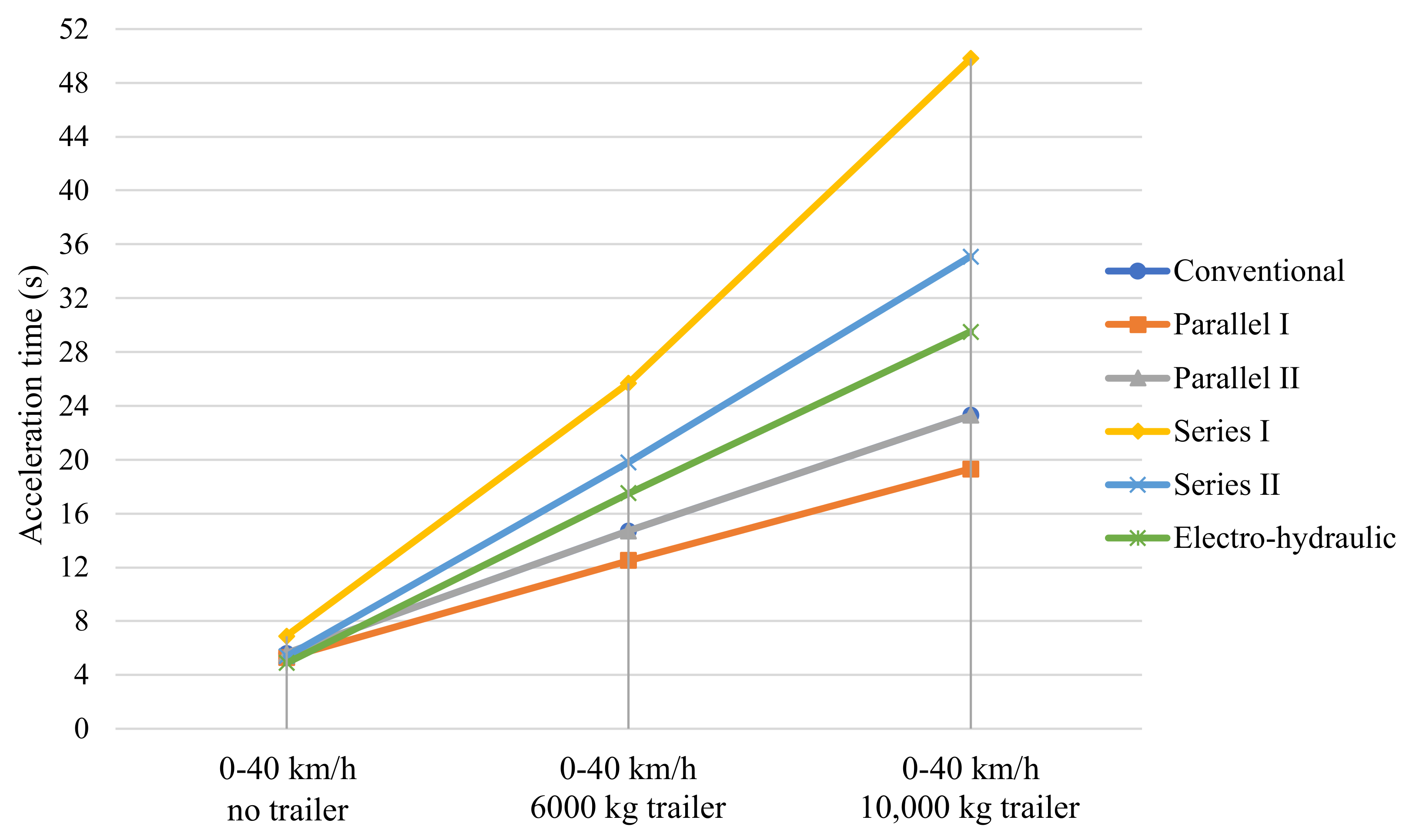
The 0–15 km/h acceleration tests provided very similar results for all the architectures thanks to the high torque multiplication given by the low-speed range gearset. On the other hand, performance analysis in the 0–40 km/h acceleration showed interesting differences between the proposed architectures, particularly when pulling the trailer. In Figure 15, results of the 0–40 km/h acceleration tests are shown. The Parallel I HET architecture showed the most promising results, as expected, in peak power capabilities. The reason clearly lies in the cooperation between the ICE and EM when it comes to providing direct traction power [31]. For the proposed characteristics of the electric components, the double energy conversion happening in the Series I and II HET configurations penalized these solutions in pure peak power capabilities. The Parallel II HET architecture showed comparable results with the CDOT version but with a smaller ICE as desired at the design stage. Interesting results were also shown by the electro-hydraulic HET architecture. Despite the not excellent performance in peak power capabilities, it is interesting to note that good acceleration performance was obtained in all the proposed tests, shining a positive light on CVT, which notably increases the user experience of such working vehicles.

3.2. Slope Performance

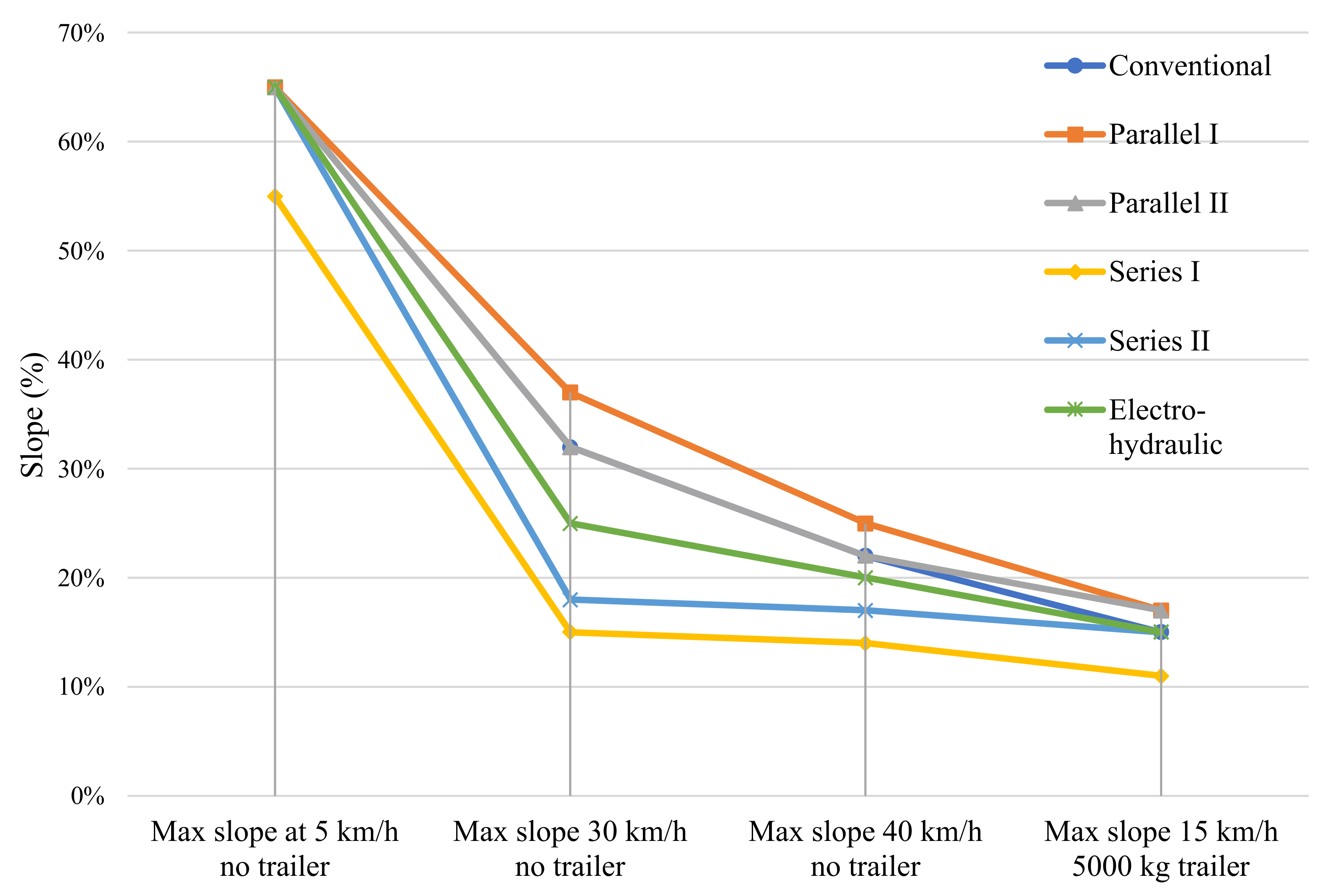
Another important test to evaluate peak power capabilities is the slope test, both with and without an attached trailer. In the first case, it is possible to evaluate the limit conditions in terms of maximum affordable slope and consequently the maximum reachable speed. In the second case, it is interesting to investigate the limit payload compatible with a certain slope. Of course, in this scenario the number of possible combinations to be investigated can increase very quickly; thus, some of the most representative operating conditions were considered. In particular, the following tests were performed:
  • Approaching of slopes at 5 km/h, 30 km/h and 40 km/h with no trailer.
  • Approaching of slopes at 15 km/h with a trailer of 5000 kg.
Figure 16 shows a summary of the results obtained by this set of tests. It is important to highlight that the numerical simulations were performed from standing starts at the base of the prescribed slope. As expected, with slopes tests being representative of peak power capabilities, the results confirmed the performances stated by the acceleration tests. The Parallel I and II HET architectures were confirmed to be the best options for performing better or at least as well as with the conventional powertrain in terms of peak performance. Additionally, in this case, the electro-hydraulic model was confirmed to have good performance with respect to the conventional powertrain but with the benefit of introducing CVT capabilities, and allowing for better control of the optimal ICE working point, decoupling it from the wheels. Additionally, in this case, the two series HET architectures did not excel in covering peaks in power demand, at least for the proposed configuration of the electric systems.

3.3. Energy Consumption Analysis

In the previous sections, peak power capabilities for the proposed HET architectures were explored to compare their performances with that of a conventional diesel-powered tractor. In this section, data were gathered to state the overall energy consumption of the proposed architectures, and thus their efficiency in daily working activities. For this reason, working scenarios involving external implements were considered to also explore performance in field activities.
Table 7 summarizes the results for this group of performance tests.
To properly approach these results, it is important to mention that Table 7 shows the differences between the overall energy required by the conventional powertrain to accomplish a specific task and the energy required by the respective proposed HET architectures to perform the same task. Thus, for the hybrid powertrains, the energy required to accomplish the simulated task was calculated as the sum of the kWh of electric energy coming from the battery pack, obtainable through the SOC level reduction, and the kWh of chemical energy produced by the fuel consumed, obtainable from the fuel consumption model presented in Section 2.1. The energy from the battery pack and the equivalent energy associated with a certain fuel consumption were summed to obtain the total energy required to accomplish the simulated task. Thus, this value intrinsically takes into account all the efficiency conversions in the chain: from tank to engine shaft, from battery to motor shaft and from generator shaft to motor shaft. The authors also want to highlight that this analysis did not aim to provide the exact values of energy consumption, which surely would require experimental characterization and validation of the models for each of the proposed HET architectures. Instead, the point was to perform a relative comparison with respect to the energy consumption of the conventional powertrain model. In this way, it was possible to highlight how all the different energy conversion efficiencies affected the final performances of the HET solutions.
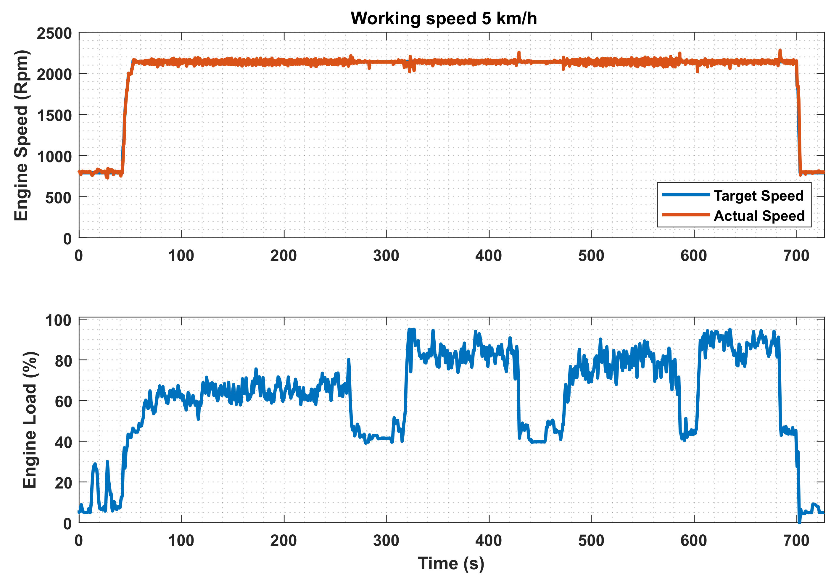
During tests with shredder, atomizer and rotary harrow, the tractor speed was fixed at 5 km/h, as measured during experimental tests conducted in previous works. As for the handling trailer tests, they consisted of evaluating the energy consumption while pulling the trailer at the constant speed of 40 km/h. These tests were all performed in CD mode to have the same energy management strategy among all the HET architectures. From results in Table 7, it is possible to see that all the HET architectures can achieve better energy efficiency in all the proposed working scenarios if compared with a conventional architecture. One of the main reasons is surely the adoption of a smaller diesel engine working closer to its high efficiency points. In these set of performance tests, both Series I and Series II HET architectures achieved better overall energy efficiency, despite the double energy conversion involved when the generator needed to provide power for the high voltage bus to supply the motor. The results confirmed the difficulty in energy consumption optimization for the parallel architectures because of the direct mechanical connections between the engine and the wheels. This consideration was validated by the results for tests involving external implements. In these test cases, both the constant vehicle speed and PTO speed allowed one to have the engine as close as possible to a high efficiency working point, in accordance with the set of gear speed combinations within the transmission. Thus, the overall energy consumption is comparable in both parallel and series HET configurations. Unfortunately, in this type of analysis the electro-hydraulic HET solution showed its main drawback: the CVT function comes at the cost of a higher overall use of the available energy (both from the tank and from the BESS).

3.4. Work Cycle Analysis

Finally, two work cycle analyses were performed to evaluate the design characteristics of the proposed BESS in daily load profiles, estimating this time the amount of fuel saving with respect to the traditional powertrain.
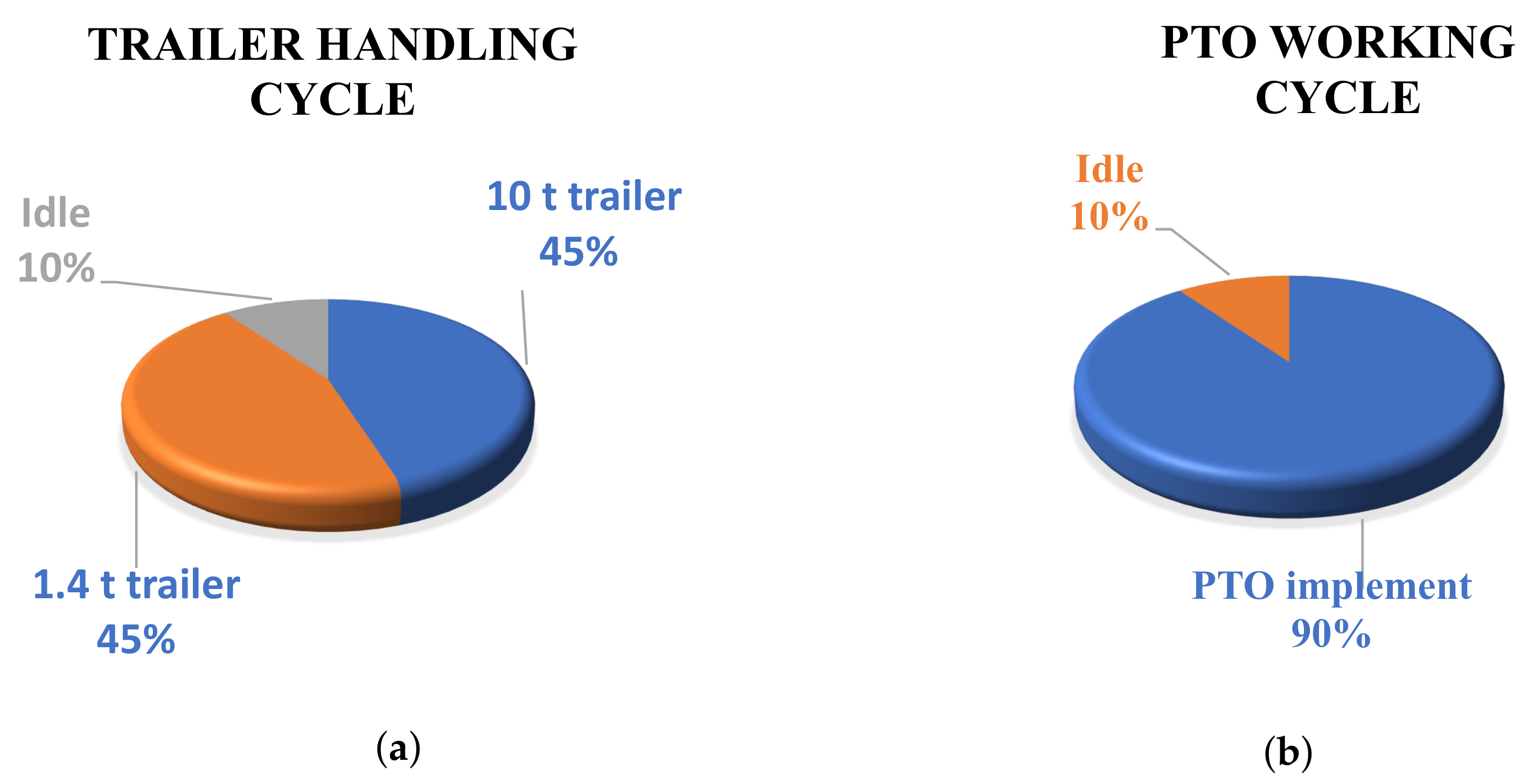
The proposed tests consisted of a full day of transportation and of a PTO-powered external implement. For the purpose of this analysis, a workday of 8 h was considered. For the transportation work scenario shown in Figure 17a, we used had the tractor traveling at maximum speed with a full load (10,000 kg) for 45% of the time and at maximum speed but with the minimum trailer mass (1400 kg) for 45% of the time. The remaining 10% was imagined as idle time, or moments when the tractor is powered on but it is not actually working (this happens very often in those moments wherein the trailer needs to be fulfilled or emptied). For the PTO work scenario, a more simple but critical load profile was identified, as shown in Figure 17b, with continuous PTO work for almost 90% of the time, and again 10% of idling time for all those moments regarding mounting and dismounting of the tool or other related operations. In order to optimize the BESS use, the hybrid powertrains were controlled to recharge the batteries when idling.
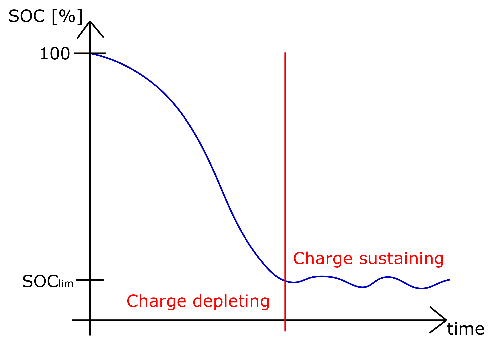
Table 8 shows the numerical outcomes of the proposed tests in terms of fuel saving with respect to the conventional powertrain. A traditional tractor is supposed to be able to complete the 8 h working cycles, and in very exceptional and intensive cases, it is possible to refuel it in a very short time. On the other hand, the autonomy is an aspect of primary importance in electrified working vehicles, because it could affect negatively a company’s productivity if it is not able to complete the planned activities. This is the reason why, looking at the working day, the CS mode of the energy management strategy is crucial to find the correct balance between the BESS discharge and overall autonomy of the proposed HET configuration. Results show that the parallel and series HET architectures managed to accomplish the proposed tasks with better fuel efficiency compared to the conventional powertrain. In particular, the series HET recorded 20.4% fuel savings in the handling trailer cycle, mainly because of the absence of the mechanical link between the thermal unit and the wheels, allowing it to work around its optimal working point. The electro-hydraulic powertrain, instead, was not able to complete the rotary harrow working cycle because of the higher power losses in the hydraulic system. The failure of the test was stated when the energy consumption of the BESS went beyond its maximum storage capability. This means that, in this case, the only way to complete the cycle was to change the working parameters to limit the energy consumption. However, this may translate in productivity reduction, or in the worst case, to not being able to perform that type of task.
As for the HET, at the end of each proposed working cycle, the SOC level was generally at 30% due to the CD mode, apart from the handling trailer cycle, where the Parallel I, Parallel II and electro-hydraulic had SOC slightly above that value. Therefore, this combination of CD and CS mode is optimal when the battery pack has the possibility of being recharged through a plug-In system. In this way, after completing the working day, the tractor can be recharged, and its SOC level can be brought back to 100% for the next working day.

4. Conclusions

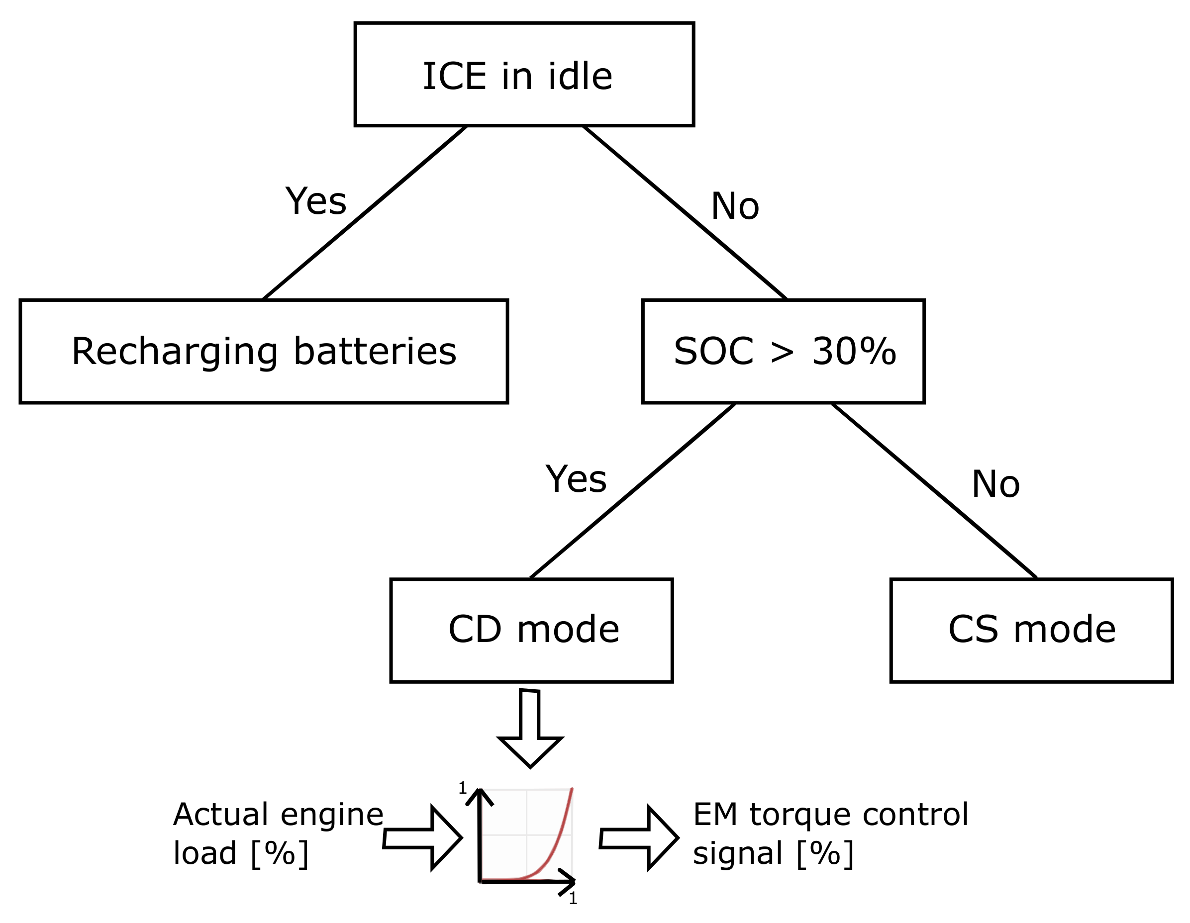
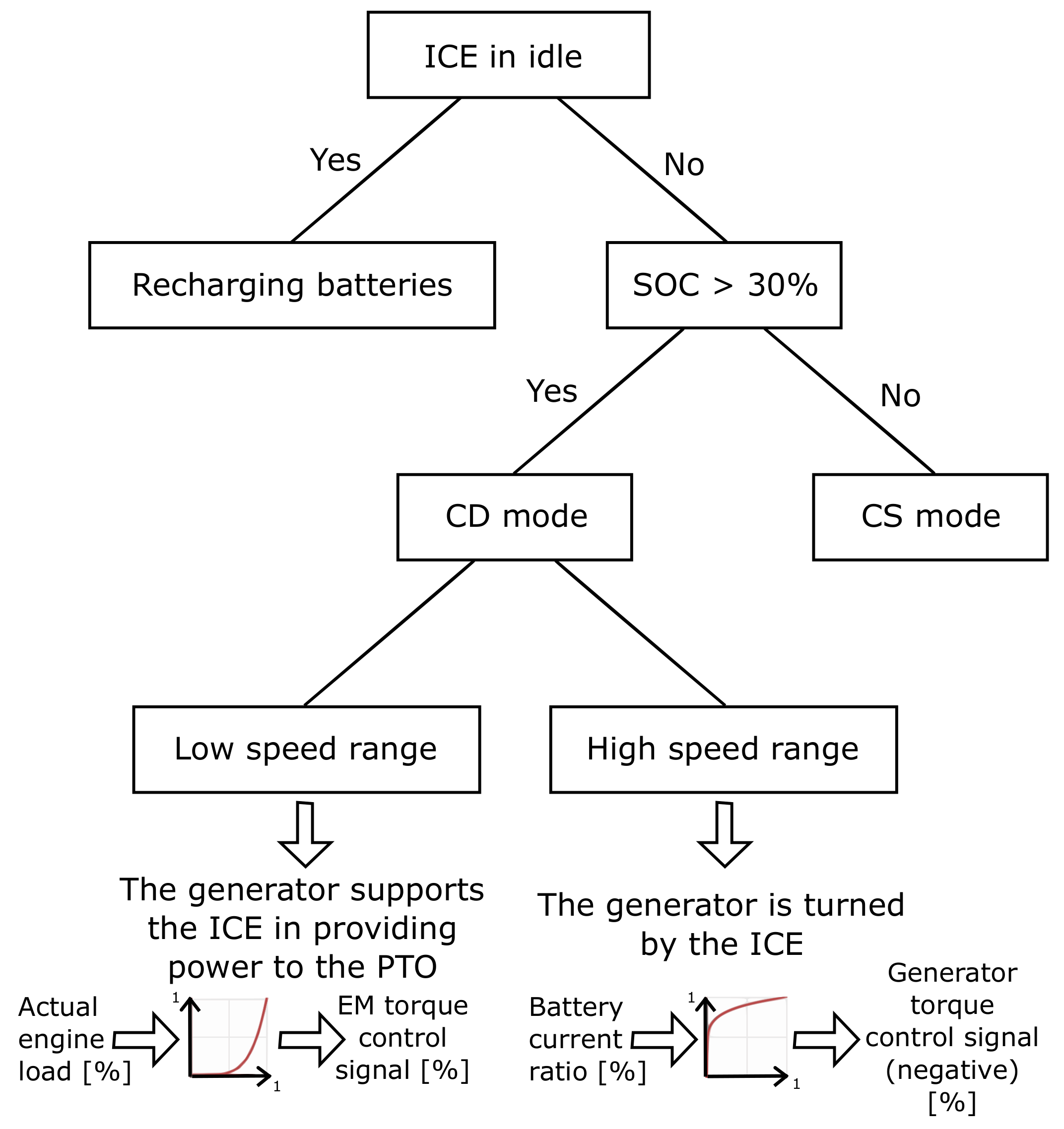
In literature, some works on the hybridization of agricultural tractors have been proposed. However, to the authors’ knowledge, there is no clear answer on what hybrid architecture could better fit specific class of tractors. In case of an orchard tractor, hybridization of the powertrain should consider the different kinds of problems that affect these vehicles. In particular, highly variable work scenarios, peak power capabilities, endurance and onboard space availability may represent true challenges in the design of the electrified powertrain. Therefore, this work aimed at highlighting the benefits and drawbacks of different hybrid solutions considering the requirements of this specialized vehicles. In this work, a numerical comparative analysis between the performance of a conventional specialized orchard tractor, propelled by a diesel-powered engine with nominal power of 73 kW, and the performances of three different HET solutions, adopting a downsized 53 kW diesel engine, was presented. Peak power capabilities and energy consumption of the conventional and HET architectures were numerically tested in a specific set of working scenarios related to experimental field measurements from previous works. For each HET architecture, an energy management strategy was proposed to properly split the power between the thermal and the electric units. These strategies were designed to prefer the ICE as primary power source and used two main operating modes depending on the BESS SOC level: charge depleting (CD) and charge sustaining (CS). Simulations were carried out to evaluate the efficiency improvements and fuel savings of the HET architectures compared to the conventional powertrain. Since the onboard BESS is the most critical energy source, for all the HET configurations, the same capacity was used. Therefore, simulations also allowed to establish the feasibility of both the voltage and capacity of the proposed BESS according to the proposed mission profiles. The results showed that HET solutions managed to have performances comparable to and even better than the conventional architecture. Moreover, they managed to achieve better fuel efficiency during normal working activities thanks to the use of a downsized engine instead of an oversized one. The downsized engine, moreover, could lead to a lower environmental impact of the vehicle and to a cost reduction for the required exhaust gas after-treatment system. Among the proposed HET solutions, parallel HET configurations performed better in terms of peak power capabilities, whereas series HET ones showed better overall efficiencies, and thus greater fuel savings. Moreover, the series HET undoubtedly presented advantages in simplifying the transmission, which can be translated into greater constructive simplicity. An electro-hydraulic HET configuration was also proposed in this work as a trade off between the need for a smaller diesel engine, helped by the electric motor, and the CVT capabilities. Performance tests showed good peak power capabilities, but lower overall efficiency due to the introduction of hydraulic losses in the hydrostatic transmission. Future works will focus on improving the limits that characterize the proposed architectures. Moreover, a deeper investigation of the control strategy should be a subject of research, since it could affect in a relevant way the performance and fuel consumption of the tractor. In addition, a deeper investigation of the battery pack and its sizing, according to the onboard space availability, deserves study. Other architectures, such as a powersplit hybrid, that theoretically could combine the advantages of both the parallel and series HET, might be explored in future research activities.

Author Contributions

The authors contributed equally to this work. All authors have read and agreed to the published version of the manuscript.

Funding

This research received no external funding.

Institutional Review Board Statement

Not applicable.

Informed Consent Statement

Not applicable.

Data Availability Statement

Not applicable.

Conflicts of Interest

The authors declare no conflict of interest.

References

  1. Gorjian, S.; Ebadi, H.; Trommsdorff, M.; Sharon, H.; Demant, M.; Schindele, S. The advent of modern solar-powered electric agricultural machinery: A solution for sustainable farm operations. J. Clean. Prod. 2021, 292, 126030. [Google Scholar] [CrossRef]
  2. Platis, D.P.; Anagnostopoulos, C.D.; Tsaboula, A.D.; Menexes, G.C.; Kalburtji, K.L.; Mamolos, A.P. Sustainability Energy Analysis, and Carbon and Water Footprint for Environmentally Friendly Farming Practices in Agroecosystems and Agroforestry. Sustainability 2019, 11, 1664. [Google Scholar] [CrossRef] [Green Version]
  3. Lovarelli, D.; Bacenetti, J. Exhaust gases emissions from agricultural tractors: State of the art and future perspectives for machinery operators. Biosyst. Eng. 2019, 186, 204–213. [Google Scholar] [CrossRef]
  4. European Parliament—Council of the European Union. Regulation (EU) 2016/1628 of the European Parliament and of the Council of 14 September 2016 on Requirements Relating to Gaseous and Particulate Pollutant Emission Limits and Type-Approval for Internal Combustion Engines for Non-Road Mobile Machinery, Amending Regulations (EU) No 1024/2012 and (EU) No 167/2013, and Amending and Repealing Directive 97/68/EC. Eur-Lex. 2016. Available online: https://eur-lex.europa.eu/legal-content/EN/TXT/?uri=CELEX:02016R1628-20210630 (accessed on 8 February 2022).
  5. Bacenetti, J.; Lovarelli, D.; Facchinetti, D.; Pessina, D. An environmental comparison of techniques to reduce pollutants emissions related to agricultural tractors. Biosyst. Eng. 2018, 171, 30–40. [Google Scholar] [CrossRef]
  6. Ye, Y.; He, L.; Wang, Z.; Jones, D.; Hollinger, G.A.; Taylor, M.E.; Zhang, Q. Orchard manoeuvring strategy for a robotic bin-handling machine. Biosyst. Eng. 2017, 169, 85–103. [Google Scholar] [CrossRef]
  7. Moreda, G.; Muñoz-García, M.; Barreiro, P. High voltage electrification of tractor and agricultural machinery—A review. Energy Convers. Manag. 2016, 115, 117–131. [Google Scholar] [CrossRef]
  8. Somà, A. Trends and Hybridization Factor for Heavy-Duty Working Vehicles; IntechOpen: Rijeka, Croatia, 2017; p. 1. [Google Scholar] [CrossRef] [Green Version]
  9. Somà, A.; Bruzzese, F.; Mocera, F.; Viglietti, E. Hybridization Factor and Performance of Hybrid Electric Telehandler Vehicle. IEEE Trans. Ind. Appl. 2016, 52, 5130–5138. [Google Scholar] [CrossRef]
  10. Mocera, F.; Somà, A. Working Cycle requirements for an electrified architecture of a vertical feed mixer vehicle. Procedia Struct. Integr. 2018, 12, 213–223. [Google Scholar] [CrossRef]
  11. Mocera, F.; Somà, A. A Review of Hybrid Electric Architectures in Construction, Handling and Agriculture Machines. In New Perspectives on Electric Vehicles [Working Title]; IntechOpen: Rijeka, Croatia, 2021. [Google Scholar] [CrossRef]
  12. Soofi, A.F.; Manshadi, S.D.; Saucedo, A. Farm electrification: A road-map to decarbonize the agriculture sector. Electr. J. 2022, 35, 107076. [Google Scholar] [CrossRef]
  13. Liu, M.; Xu, L.; Zhou, Z. Design of a Load Torque Based Control Strategy for Improving Electric Tractor Motor Energy Conversion Efficiency. Math. Probl. Eng. 2016, 2016, 1–14. [Google Scholar] [CrossRef] [Green Version]
  14. Vogt, H.H.; de Melo, R.R.; Daher, S.; Schmuelling, B.; Antunes, F.L.M.; dos Santos, P.A.; Albiero, D. Electric tractor system for family farming: Increased autonomy and economic feasibility for an energy transition. J. Energy Storage 2021, 40, 102744. [Google Scholar] [CrossRef]
  15. Melo, R.R.; Antunes, F.L.; Daher, S.; Vogt, H.H.; Albiero, D.; Tofoli, F.L. Conception of an electric propulsion system for a 9 kW electric tractor suitable for family farming. IET Electr. Power Appl. 2019, 13, 1993–2004. [Google Scholar] [CrossRef]
  16. Li, T.; Xie, B.; Li, Z.; Li, J. Design and Optimization of a Dual-Input Coupling Powertrain System: A Case Study for Electric Tractors. Appl. Sci. 2020, 10, 1608. [Google Scholar] [CrossRef] [Green Version]
  17. Dalboni, M.; Santarelli, P.; Patroncini, P.; Soldati, A.; Concari, C.; Lusignani, D. Electrification of a Compact Agricultural Tractor: A Successful Case Study. In Proceedings of the 2019 IEEE Transportation Electrification Conference and Expo (ITEC), Detroit, MI, USA, 19–21 June 2019; pp. 1–6. [Google Scholar] [CrossRef]
  18. Mocera, F.; Somà, A. Analysis of a Parallel Hybrid Electric Tractor for Agricultural Applications. Energies 2020, 13, 3055. [Google Scholar] [CrossRef]
  19. Mocera, F. A Model-Based Design Approach for a Parallel Hybrid Electric Tractor Energy Management Strategy Using Hardware in the Loop Technique. Vehicles 2020, 3, 1. [Google Scholar] [CrossRef]
  20. Baek, S.Y.; Baek, S.M.; Jeon, H.H.; Kim, W.S.; Kim, Y.S.; Sim, T.Y.; Choi, K.H.; Hong, S.J.; Kim, H.; Kim, Y.J. Traction Performance Evaluation of the Electric All-Wheel-Drive Tractor. Sensors 2022, 22, 785. [Google Scholar] [CrossRef]
  21. Baek, S.Y.; Kim, Y.S.; Kim, W.S.; Baek, S.M.; Kim, Y.J. Development and Verification of a Simulation Model for 120 kW Class Electric AWD (All-Wheel-Drive) Tractor during Driving Operation. Energies 2020, 13, 2422. [Google Scholar] [CrossRef]
  22. Rossi, C.; Pontara, D.; Falcomer, C.; Bertoldi, M.; Mandrioli, R. A Hybrid–Electric Driveline for Agricultural Tractors Based on an e-CVT Power-Split Transmission. Energies 2021, 14, 6912. [Google Scholar] [CrossRef]
  23. Rossi, C. E-CVT power split transmission for hybrid-electric vehicles. In Proceedings of the 2013 9th IEEE Vehicle Power and Propulsion Conference, Beijing, China, 15–18 October 2013; pp. 138–145. [Google Scholar] [CrossRef]
  24. Mocera, F.; Martini, V. Numerical Performance Investigation of a Hybrid eCVT Specialized Agricultural Tractor. Appl. Sci. 2022, 12, 2438. [Google Scholar] [CrossRef]
  25. Grisso, R.B. Predicting Tractor Diesel Fuel Consumption. Virginia Cooperative Extension. Available online: https://vtechworks.lib.vt.edu/bitstream/handle/10919/47472/442-073_pdf.pdf (accessed on 8 February 2022).
  26. Wang, Z.; Feng, G.; Zhen, D.; Gu, F.; Ball, A. A review on online state of charge and state of health estimation for lithium-ion batteries in electric vehicles. Energy Rep. 2021, 7, 5141–5161. [Google Scholar] [CrossRef]
  27. Varani, M.; Mattetti, M.; Molari, G. Performance Evaluation of Electrically Driven Agricultural Implements Powered by an External Generator. Agronomy 2021, 11, 1447. [Google Scholar] [CrossRef]
  28. Gao, D.; Zhang, W.; Shen, A.; Wang, Y. Parameter Design and Energy Control of the Power Train in a Hybrid Electric Boat. Energies 2017, 10, 1028. [Google Scholar] [CrossRef] [Green Version]
  29. Zhang, S.; Zhang, J. Optimal State-of-Charge Value for Charge-Sustaining Mode of Plug-In Hybrid Electric Vehicles. IEEE Access 2020, 8, 187959–187964. [Google Scholar] [CrossRef]
  30. Mocera, F.; Vergori, E.; Soma, A. Battery Performance Analysis for Working Vehicle Applications. IEEE Trans. Ind. Appl. 2020, 56, 644–653. [Google Scholar] [CrossRef]
  31. Sieg, C.; Küçükay, F. Benchmarking of Dedicated Hybrid Transmissions. Vehicles 2020, 2, 6. [Google Scholar] [CrossRef] [Green Version]
Figure 1. Simulink model architecture for the conventional tractor.
Energies 15 01944 g001
Figure 3. 1D longitudinal tractor model.
Energies 15 01944 g003
Figure 4. Field test data during work activities with a rotary harrow at 5 km/h.
Energies 15 01944 g004
Figure 5. Schematic powertrain power flow diagram.
Energies 15 01944 g005
Figure 7. Schematic representation of the parallel hybrid architecture.
Energies 15 01944 g007
Figure 8. Typical torque–speed and power–speed profiles of the electric machines considered in this work.
Energies 15 01944 g008
Figure 9. Schematic representation of the series architecture.
Energies 15 01944 g009
Figure 10. Schematic representation of the electro-hydraulic architecture.
Energies 15 01944 g010
Figure 11. Efficiency curve of the hydraulic motor and hydraulic pump.
Energies 15 01944 g011
Figure 13. Parallel hybrid and electro-hydraulic hybrid control strategy.
Energies 15 01944 g013
Figure 14. The control strategy of the parallel hybrid and electro-hydraulic hybrid systems.
Energies 15 01944 g014
Figure 15. Acceleration performance comparison.
Energies 15 01944 g015
Figure 16. Comparison between the architectures’ slope performances.
Energies 15 01944 g016
Figure 17. Daily work scenarios (8 h): (a) transportation; (b) field activities with implement.
Energies 15 01944 g017
Table 1. Main characteristics of the orchard tractor.
Vehicle Properties
Mass2500 kg
Vehicle wheelbase1900 mm
Track width1850 mm
Wheel radius680 mm
Nominal power75 kW @ 2300 rpm
Top speed40 km/h
Minimum speed0.4 km/h
Table 2. Relevant characteristics of the proposed implement-related activities.
ShredderAtomizerRotart Harrow
Min power (kW)123236
Mean power (kW)193644
Max power (kW)264052
Vehicle speed (km/h)555
Table 3. Main properties of the battery pack.
Voltage600 V
Capacity16 kWh
Continuous Discharge 3 · C n o m
Peak Discharge 5 · C n o m
Continuous Charge 0.5· C n o m
Peak Charge 1 · C n o m
Table 4. Main properties of the EM adopted by the parallel architectures.
Parallel IParallel II
Nominal power (kW)3022
Maximum torque (Nm)13094
Nominal efficiency (%)9393
Table 5. Main properties of the series architectures.
Series ISeries II
Generator nominal power (kW)5656
Generator maximum torque (Nm)230230
Generator nominal efficiency (%)9393
Motor nominal power (kW)5463
Motor maximum torque (Nm)90100
Motor nominal efficiency (%)9393
Transmission ratios97; 35103; 38
Table 6. Main properties of the electro-hydraulic architecture.
EM nominal power22 kW
EM maximum torque94 Nm
Pump max displacement80 cm3
Pump nominal pressure gain250 bar
Pump nominal rotational speed1500 rpm
Hydraulic motor displacement80 cm3
Hydraulic motor nominal pressure drop250 bar
Hydraulic motor nominal rotational speed1500 rpm
Transmission ratios38; 13
Table 7. Energy consumption in CD mode compared to the conventional powertrain.
ParallelParallelSeriesSeriesElectro
IIIIIIHydraulic
Shredder−15.8%−15.8%−15.1%−15.1%−8.8%
Atomizer−13.3%−12.9%−12.1%−12.1%−7.1%
Rotary harrow−12.4%−12.2%−11.8%−11.8%−7.5%
Handling a trailer at 0–40 km/h
6000 kg trailer−15.4%−15.4%−22.1%−22.1%−6.4%
10,000 kg trailer−16.4%−15.9%−17.7%−17.7%−7.0%
Avg−14.7%−14.4%−15.8%−15.8%−7.4%
Table 8. Fuel consumption on working cycles compared to conventional powertrain.
ParallelParallelSeriesSeriesElectro
IIIIIIHydraulic
Shredder cycle−15.7%−15.7%−15.0%−15.0%−9.5%
Atomizer cycle−11.3%−11.5%−10.4%−10.4%−5.9%
Rotary harrow cycle−9.5%−9.8%−9.0%−9.0%FAILED *
Handling trailer cycle−17.4%−17.4%−20.4%−20.4%−7.9%
Avg−13.5−13.6−13.7−13.7−7.8 *
* not compatible with the 16 kWh BESS size.
Publisher’s Note: MDPI stays neutral with regard to jurisdictional claims in published maps and institutional affiliations.

