
A Review about Flux-Weakening Operating Limits and Control Techniques for Synchronous Motor Drives


Abstract
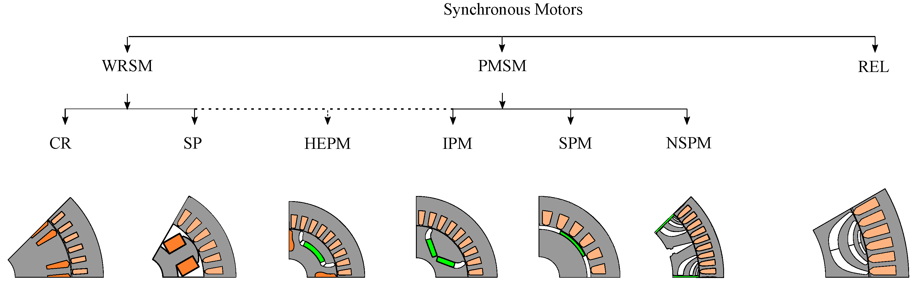
:1. Introduction
- Section 2 defines the steady-state operation loci of PMSMs, distinguishing between MTPA and FW operation mode.
- Section 3 resumes some considerations concerning the design of SPM, IPM, REL and HEPM motors for given FW performances. A per unit (p.u.) analysis is proposed to generalize the design guidelines.
- Section 4 presents FW control architectures, discussing advantages and drawbacks. The widespread feed-back, feed-forward and hybrid architectures are presented, together with other promising configurations.
2. Motor Model and Operating Condition
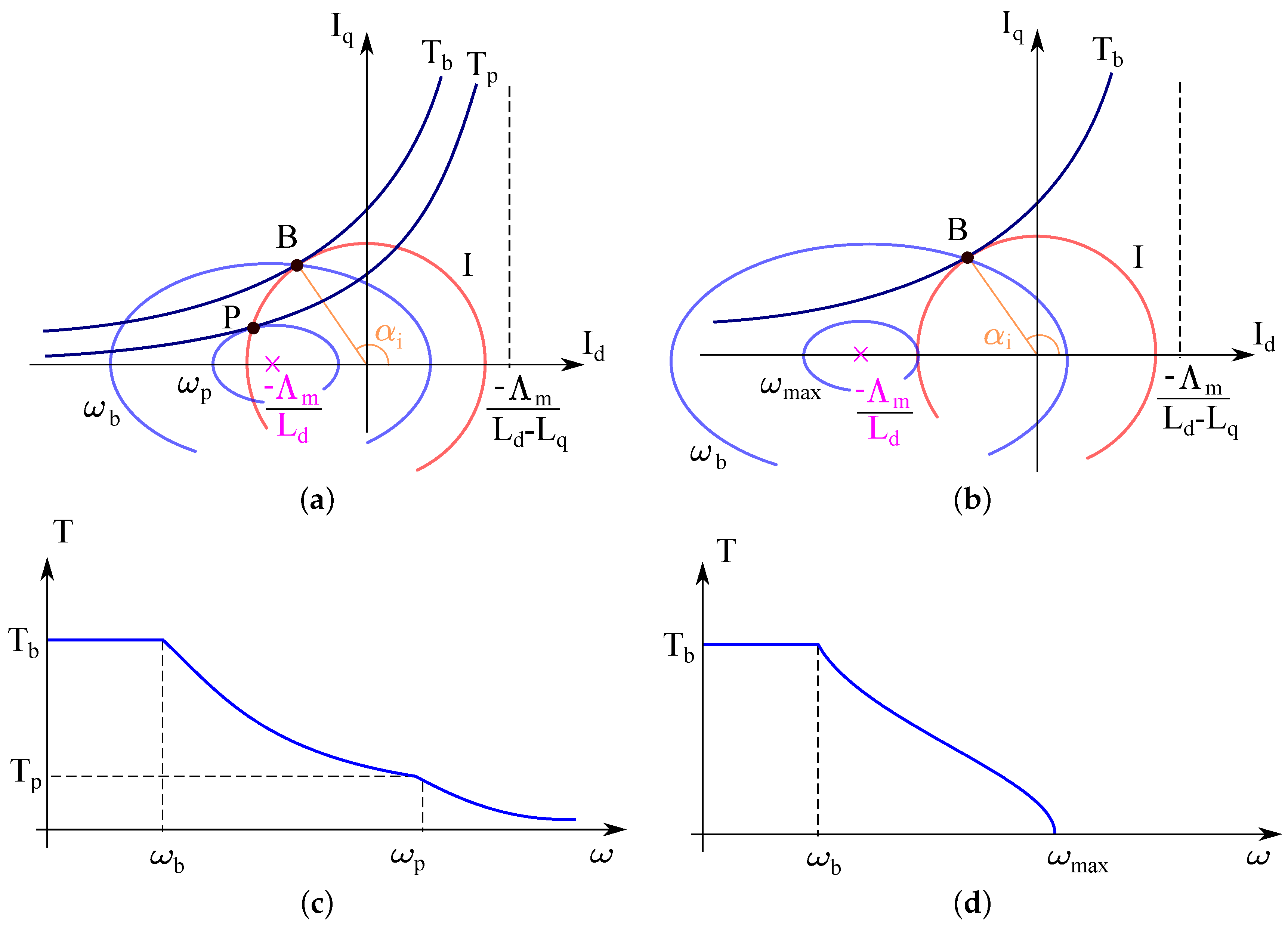
2.1. Constant Maximum Available Torque Region
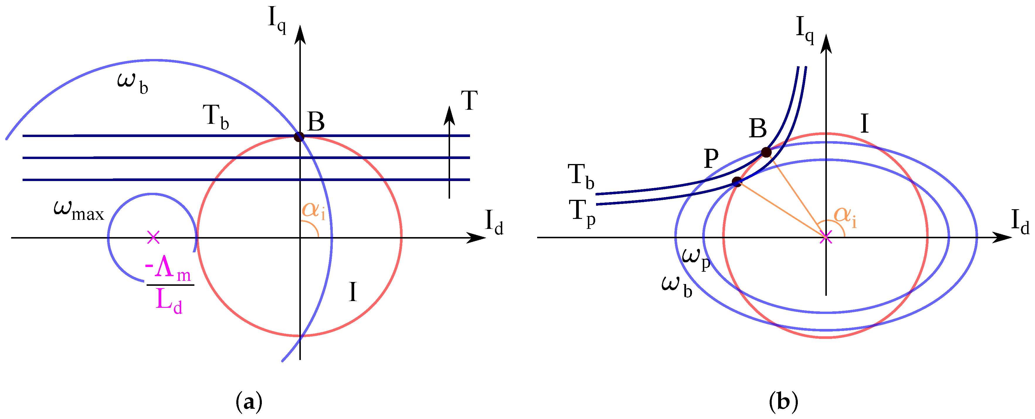
2.2. Flux-Weakening: Constant Maximum Available Volt-Ampere Region
2.3. Flux-Weakening: Decreasing Volt-Ampere Region
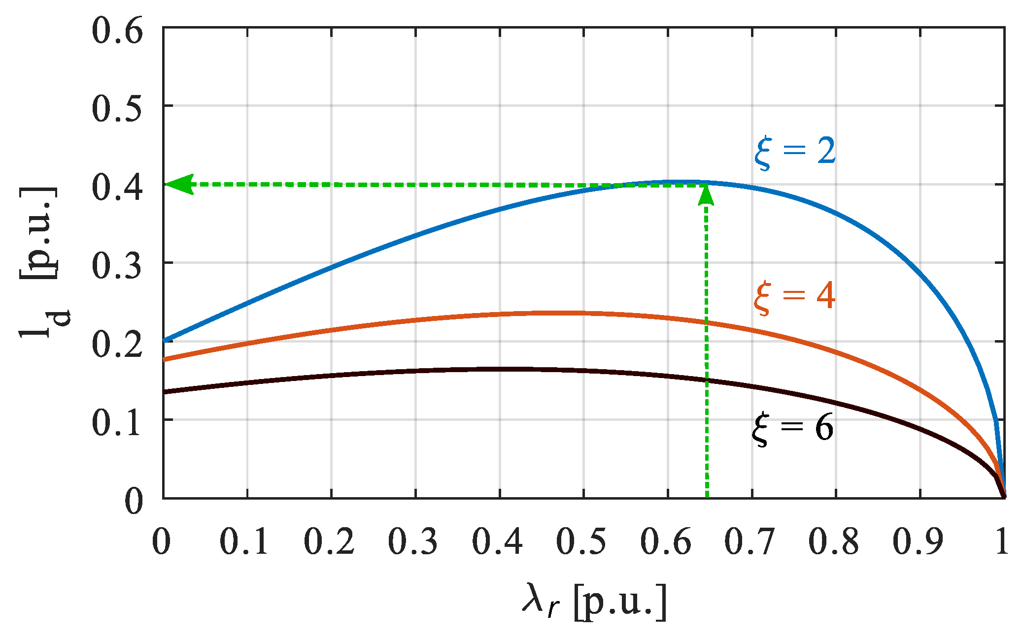
3. Design of Electric Motors for Given FW Requirements
- 1.
- Set the desired values of maximum FW speed and torque ;
- 2.
- A suitable couple of rotor flux linkage and saliency ratio must be selected;
- 3.
- In order to fulfill the specification at nominal point of base torque , voltage , and speed , only one value of direct inductance and current i can assure the desired performance once and are set;
- 4.
- Finally, the defined p.u. parameters can be reported to the absolute magnitude value and then the machine can be designed. These values must be realized with a proper motor design by taking into account practical limitation.
3.1. PM Motors
3.2. Pure Reluctance Motor
3.3. Motor with Rotor Excitation Windings
4. Flux-Weakening Control Strategies
- feed-forward architectures, which do not implement any voltage feedback;
- feedback schemes, where only a voltage feedback provides the FW operation;
- hybrid methods, which couple both a voltage feedback and feed-forward action.
4.1. Feed-Forward Schemes
4.2. Feedback Schemes
4.3. Hybrid FW Schemes
4.4. DC-Bus Voltage Use
4.5. Direct Flux Control
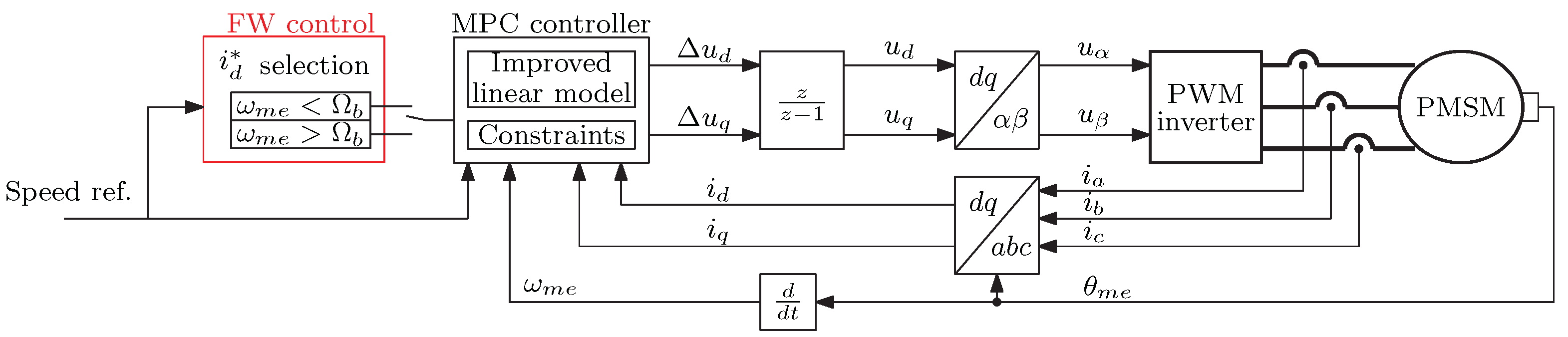
4.6. Model Predictive Control
4.7. Sensorless Control
5. Conclusions
Author Contributions
Funding
Conflicts of Interest
Appendix A. Normalized Parameters

| P.U. QUANTITIES | |||
|---|---|---|---|
| Torque | Electrical speed | ||
| Phase current | Rotor flux linkage | ||
| Phase voltage | Synchronous inductance | ||
References
- Soong, W.; Miller, T. Practical field-weakening performance of the five classes of brushless synchronous AC motor drive. In Proceedings of the 1993 Fifth European Conference on Power Electronics and Applications, Brighton, UK, 13–16 September 1993; Volume 5, pp. 303–310. [Google Scholar]
- Sebastiangordon, T.; Slemon, G.R. Operating Limits of Inverter-Driven Permanent Magnet Motor Drives. IEEE Trans. Ind. Appl. 1987, IA-23, 327–333. [Google Scholar] [CrossRef]
- Fontana, M.; Bianchi, N. Design and Analysis of Normal Saliency IPM Spoke Motor. IEEE Trans. Ind. Appl. 2020, 56, 3625–3635. [Google Scholar] [CrossRef]
- Amara, Y.; Vido, L.; Gabsi, M.; Hoang, E.; Ben Ahmed, A.H.; Lecrivain, M. Hybrid Excitation Synchronous Machines: Energy-Efficient Solution for Vehicles Propulsion. IEEE Trans. Emergy Sel. Top. Power Electron. 2009, 58, 2137–2149. [Google Scholar] [CrossRef]
- Sneyers, B.; Novotny, D.W.; Lipo, T.A. Field Weakening in Buried Permanent Magnet AC Motor Drives. IEEE Trans. Ind. Appl. IA-21, 398–407. [CrossRef]
- Jahns, T.M.; Kliman, G.B.; Neumann, T.W. Interior Permanent-Magnet Synchronous Motors for Adjustable-Speed Drives. IEEE Trans. Ind. Appl. 1986, IA-22, 738–747. [Google Scholar] [CrossRef]
- Jahns, T.M. Flux-Weakening Regime Operation of an Interior Permanent-Magnet Synchronous Motor Drive. IEEE Trans. Ind. Appl. 1987, IA-23, 681–689. [Google Scholar] [CrossRef]
- Sepulchre, L.; Fadel, M.; Pietrzak-David, M.; Porte, G. MTPV Flux-Weakening Strategy for PMSM High Speed Drive. IEEE Trans. Ind. Appl. 2018, 54, 6081–6089. [Google Scholar] [CrossRef]
- Xia, Z.; Nalakath, S.; Tarvirdilu-Asl, R.; Sun, Y.; Wiseman, J.; Emadi, A. Online Optimal Tracking Method for Interior Permanent Magnet Machines With Improved MTPA and MTPV in Whole Speed and Torque Ranges. IEEE Trans. Power Electron. 2020, 35, 9753–9769. [Google Scholar] [CrossRef]
- Xu, L.; Ye, L.; Zhen, L.; El-Antably, A. A new design concept of permanent magnet machine for flux weakening operation. IEEE Trans. Ind. Appl. 1995, 31, 373–378. [Google Scholar] [CrossRef] [Green Version]
- Pellegrino, G.; Armando, E.; Guglielmi, P. Direct Flux Field-Oriented Control of IPM Drives With Variable DC Link in the Field-Weakening Region. IEEE Trans. Ind. Appl. 2009, 45, 1619–1627. [Google Scholar] [CrossRef]
- Toso, F.; Carlet, P.G.; Preindl, M.; Bolognani, S. Active-Flux-Based Motion-Sensorless Control of PMSM Using Moving Horizon Estimator. In Proceedings of the 2018 IEEE 9th International Symposium on Sensorless Control for Electrical Drives (SLED), Helsinki, Finland, 13–14 September 2018; pp. 78–83. [Google Scholar] [CrossRef]
- Favato, A.; Carlet, P.G.; Toso, F.; Torchio, R.; Bolognani, S. Integral Model Predictive Current Control for Synchronous Motor Drives. IEEE Trans. Power Electron. 2021, 36, 13293–13303. [Google Scholar] [CrossRef]
- Ortombina, L.; Karamanakos, P.; Zigliotto, M. Robustness Analysis of Long-Horizon Direct Model Predictive Control: Permanent Magnet Synchronous Motor Drives. In Proceedings of the 2020 IEEE 21st Workshop on Control and Modeling for Power Electronics (COMPEL), Aalborg, Denmark, 9–12 November 2020; pp. 1–8. [Google Scholar] [CrossRef]
- Dianov, A.; Tinazzi, F.; Calligaro, S.; Bolognani, S. Review and Classification of MTPA Control Algorithms for Synchronous Motors. IEEE Trans. Power Electron. 2022, 37, 3990–4007. [Google Scholar] [CrossRef]
- Yamazaki, K.; Seto, Y. Iron loss analysis of interior permanent-magnet synchronous motors-variation of main loss factors due to driving condition. IEEE Trans. Ind. Appl. 2006, 42, 1045–1052. [Google Scholar] [CrossRef]
- Morimoto, S.; Takeda, Y.; Hirasa, T.; Taniguchi, K. Expansion of operating limits for permanent magnet motor by current vector control considering inverter capacity. IEEE Trans. Ind. Appl. 1990, 26, 866–871. [Google Scholar] [CrossRef]
- Soong, W.; Miller, T. Theoretical limitations to the field-weakening performance of the five classes of brushless synchronous AC motor drive. In Proceedings of the 1993 Sixth International Conference on Electrical Machines and Drives, Oxford, UK, 8–10 September 1993; pp. 127–132. [Google Scholar]
- Hackl, C.M.; Kullick, J.; Eldeeb, H.; Horlbeck, L. Analytical computation of the optimal reference currents for MTPC/MTPA, MTPV and MTPF operation of anisotropic synchronous machines considering stator resistance and mutual inductance. In Proceedings of the 2017 19th European Conference on Power Electronics and Applications (EPE’17 ECCE Europe), Warsaw, Poland, 11–14 September 2017; pp. P.1–P.10. [Google Scholar] [CrossRef]
- Adnanes, A.; Undeland, T. Optimum torque performance in PMSM drives above rated speed. In Proceedings of the Conference Record of the 1991 IEEE Industry Applications Society Annual Meeting, Dearborn, MI, USA, 28 September–4 October 1991; Volume 1, pp. 169–175. [Google Scholar] [CrossRef]
- Schiferl, R.; Lipo, T. Power capability of salient pole permanent magnet synchronous motors in variable speed drive applications. IEEE Trans. Ind. Appl. 1990, 26, 115–123. [Google Scholar] [CrossRef]
- Betz, R.; Jovanovic, M.; Lagerquist, R.; Miller, T. Aspects of the control of synchronous reluctance machines including saturation and iron losses. In Proceedings of the Conference Record of the 1992 IEEE Industry Applications Society Annual Meeting, Houston, TX, USA, 4–9 October 1992; Volume 1, pp. 456–463. [Google Scholar] [CrossRef]
- Dang, L.; Bernard, N.; Bracikowski, N.; Berthiau, G. Design Optimization with Flux Weakening of High-Speed PMSM for Electrical Vehicle Considering the Driving Cycle. IEEE Trans. Ind. Electron. 2017, 64, 9834–9843. [Google Scholar] [CrossRef]
- Bianchi, N.; Bolognani, S. Parameters and volt-ampere ratings of a synchronous motor drive for flux-weakening applications. IEEE Trans. Power Electron. 1997, 12, 895–903. [Google Scholar] [CrossRef]
- Bianchi, N.; Bolognani, S. Unified approach to the analysis and design of an AC motor drive for flux-weakening operations. In Proceedings of the Conference Record of 1998 IEEE Industry Applications Conference. Thirty-Third IAS Annual Meeting, St. Louis, MO, USA, 12–15 October 1998; Volume 1, pp. 95–102. [Google Scholar] [CrossRef]
- Pellegrino, G.; Vagati, A.; Guglielmi, P.; Boazzo, B. Performance Comparison Between Surface-Mounted and Interior PM Motor Drives for Electric Vehicle Application. IEEE Trans. Ind. Electron. 2012, 59, 803–811. [Google Scholar] [CrossRef] [Green Version]
- Bianchi, N.; Bolognani, S.; Frare, P. Design criteria for high-efficiency SPM synchronous motors. IEEE Trans. Energy Convers. 2006, 21, 396–404. [Google Scholar] [CrossRef]
- Li, Y.; Bobba, D.; Sarlioglu, B. Design and Optimization of a Novel Dual-Rotor Hybrid PM Machine for Traction Application. IEEE Trans. Ind. Electron. 2018, 65, 1762–1771. [Google Scholar] [CrossRef]
- Kawanishi, K.; Matsuo, K.; Mizuno, T.; Yamada, K.; Okitsu, T.; Matsuse, K. Development and Performance of High-Speed SPM Synchronous Machine. In Proceedings of the 2018 International Power Electronics Conference (IPEC-Niigata 2018-ECCE Asia), Niigata, Japan, 20–24 May 2018; pp. 169–176. [Google Scholar] [CrossRef]
- Abeyrathne, I.P.; Toulabi, M.S.; Filizadeh, S. Design Optimization and Performance Prediction of Synchronous Reluctance Motors. In Proceedings of the 2018 21st International Conference on Electrical Machines and Systems (ICEMS), Jeju, Kore, 7–10 October 2018; pp. 576–581. [Google Scholar] [CrossRef]
- Vagati, A.; Pastorelli, M.; Francheschini, G.; Petrache, S. Design of low-torque-ripple synchronous reluctance motors. IEEE Trans. Ind. Appl. 1998, 34, 758–765. [Google Scholar] [CrossRef]
- Morimoto, S.; Ooi, S.; Inoue, Y.; Sanada, M. Experimental Evaluation of a Rare-Earth-Free PMASynRM With Ferrite Magnets for Automotive Applications. IEEE Trans. Ind. Electron. 2014, 61, 5749–5756. [Google Scholar] [CrossRef]
- Bianchi, N.; Cinti, L.; Michieletto, D. Hybrid Excitation PM Synchronous Motors: Part I Per Unit Analysis. IEEE Trans. Energy Convers. 2021, 37, 487–494. [Google Scholar] [CrossRef]
- Bianchi, N.; Michieletto, D.; Cinti, L. Hybrid Excitation PM Synchronous Motors: Part II—Finite Element Analysis. IEEE Trans. Energy Convers. 2021, 37, 495–504. [Google Scholar] [CrossRef]
- Rossi, C.; Casadei, D.; Pilati, A.; Marano, M. Wound Rotor Salient Pole Synchronous Machine Drive for Electric Traction. In Proceedings of the Conference Record of the 2006 IEEE Industry Applications Conference Forty-First IAS Annual Meeting, Tampa, FL, USA, 8–12 October 2006; Volume 3, pp. 1235–1241. [Google Scholar] [CrossRef]
- Cinti, L.; Bianchi, N. Hybrid-Excited PM Motor for Electric Vehicle. Energies 2021, 14, 916. [Google Scholar] [CrossRef]
- Cinti, L.; Michieletto, D.; Bianchi, N.; Bertoluzzo, M. A Comparison between Hybrid Excitation and Interior Permanent Magnet Motors. In Proceedings of the 2021 IEEE Workshop on Electrical Machines Design, Control and Diagnosis (WEMDCD), Modena, Italy, 8–9 April 2021; pp. 10–15. [Google Scholar] [CrossRef]
- Cinti, L.; Carlucci, M.; Bianchi, N.; Bertoluzzo, M. Electro-Magnetic and Structural Analysis of Six-Pole Hybrid-Excited Permanent Magnet Motors. Electronics 2021, 10, 2051. [Google Scholar] [CrossRef]
- Amara, Y.; Hlioui, S.; Ahmed, H.B.; Gabsi, M. Power Capability of Hybrid Excited Synchronous Motors in Variable Speed Drives Applications. IEEE Trans. Magn. 2019, 55, 1–12. [Google Scholar] [CrossRef]
- Jacob, J.; Bottesi, O.; Calligaro, S.; Petrella, R. Design Criteria for Flux-Weakening Control Bandwidth and Voltage Margin in IPMSM Drives Considering Transient Conditions. IEEE Trans. Ind. Appl. 2021, 57, 4884–4900. [Google Scholar] [CrossRef]
- Barcaro, M.; Bianchi, N.; Magnussen, F. Rotor Flux-Barrier Geometry Design to Reduce Stator Iron Losses in Synchronous IPM Motors Under FW Operations. IEEE Trans. Ind. Appl. 2010, 46, 1950–1958. [Google Scholar] [CrossRef]
- Tursini, M.; Chiricozzi, E.; Petrella, R. Feedforward Flux-Weakening Control of Surface-Mounted Permanent-Magnet Synchronous Motors Accounting for Resistive Voltage Drop. IEEE Trans. Ind. Electron. 2010, 57, 440–448. [Google Scholar] [CrossRef]
- Wang, S.; Kang, J.; Degano, M.; Galassini, A.; Gerada, C. An Accurate Wide-Speed Range Control Method of IPMSM Considering Resistive Voltage Drop and Magnetic Saturation. IEEE Trans. Ind. Electron. 2020, 67, 2630–2641. [Google Scholar] [CrossRef]
- Chen, Y.; Huang, X.; Wang, J.; Niu, F.; Zhang, J.; Fang, Y.; Wu, L. Improved Flux-Weakening Control of IPMSMs Based on Torque Feedforward Technique. IEEE Trans. Power Electron. 2018, 33, 10970–10978. [Google Scholar] [CrossRef]
- Hoang, K.D.; Aorith, H.K.A. Online Control of IPMSM Drives for Traction Applications Considering Machine Parameter and Inverter Nonlinearities. IEEE Trans. Transp. Electrif. 2015, 1, 312–325. [Google Scholar] [CrossRef] [Green Version]
- Wang, J.; Wu, J.; Gan, C.; Sun, Q. Comparative study of flux-weakening control methods for PMSM drive over wide speed range. In Proceedings of the 2016 19th International Conference on Electrical Machines and Systems (ICEMS), Chiba, Japan, 13–16 November 2016; pp. 1–6. [Google Scholar]
- Zhang, Z.; Nahid-Mobarakeh, B.; Emadi, A. Adaptive Voltage Controller for Flux-weakening Operation in PMSM Drives. In Proceedings of the IECON 2021—47th Annual Conference of the IEEE Industrial Electronics Society, Toronto, ON, Canada, 13–16 October 2021; pp. 1–6. [Google Scholar] [CrossRef]
- Pothi, N. Improvement of flux-weakening control of surface mounted permanent magnet synchronous machine considering inverter nonlinearity. In Proceedings of the 2017 International Electrical Engineering Congress (iEECON), Pattaya, Thailand, 8–10 March 2017; pp. 1–4. [Google Scholar] [CrossRef]
- Nalepa, R.; Orlowska-Kowalska, T. Optimum Trajectory Control of the Current Vector of a Nonsalient-Pole PMSM in the Field-Weakening Region. IEEE Trans. Ind. Electron. 2012, 59, 2867–2876. [Google Scholar] [CrossRef]
- Miguel-Espinar, C.; Heredero-Peris, D.; Gross, G.; Llonch-Masachs, M.; Montesinos-Miracle, D. Maximum Torque per Voltage Flux-Weakening Strategy with Speed Limiter for PMSM Drives. IEEE Trans. Ind. Electron. 2021, 68, 9254–9264. [Google Scholar] [CrossRef]
- Manzolini, V.; Da Rù, D.; Bolognani, S. An Effective Flux Weakening Control of a SyRM Drive Including MTPV Operation. IEEE Trans. Ind. Appl. 2019, 55, 2700–2709. [Google Scholar] [CrossRef]
- Taha, W.; Emadi, A. Online Non-Parametric Auto-Tuning of Flux Weakening Controller for IPMSM Drives using Modified Relay Feedback Test. In Proceedings of the 2021 IEEE Transportation Electrification Conference Expo (ITEC), Chicago, IL, USA, 21–25 June 2021; pp. 309–314. [Google Scholar] [CrossRef]
- Bolognani, S.; Calligaro, S.; Petrella, R. Adaptive Flux-Weakening Controller for Interior Permanent Magnet Synchronous Motor Drives. IEEE Trans. Emergy Sel. Top. Power Electron. 2014, 2, 236–248. [Google Scholar] [CrossRef]
- Borocci, G.; Capponi, F.G.; De Donato, G.; Caricchi, F. Closed-Loop Flux-Weakening Control of Hybrid-Excitation Synchronous Machine Drives. IEEE Trans. Ind. Appl. 2017, 53, 1116–1126. [Google Scholar] [CrossRef]
- Xu, W.; Ismail, M.M.; Liu, Y.; Islam, M.R. Parameter Optimization of Adaptive Flux-Weakening Strategy for Permanent-Magnet Synchronous Motor Drives Based on Particle Swarm Algorithm. IEEE Trans. Power Electron. 2019, 34, 12128–12140. [Google Scholar] [CrossRef] [Green Version]
- Kwon, T.S.; Sul, S.K.; Alberti, L.; Bianchi, N. Design and Control of an Axial-Flux Machine for a Wide Flux-Weakening Operation Region. IEEE Trans. Ind. Appl. 2009, 45, 1258–1266. [Google Scholar] [CrossRef]
- Zhu, Z.; Chen, Y.; Howe, D. Online optimal flux-weakening control of permanent-magnet brushless AC drives. IEEE Trans. Ind. Appl. 2000, 36, 1661–1668. [Google Scholar] [CrossRef] [Green Version]
- Trancho, E.; Ibarra, E.; Arias, A.; Kortabarria, I.; Jurgens, J.; Marengo, L.; Fricassè, A.; Gragger, J.V. PM-Assisted Synchronous Reluctance Machine Flux Weakening Control for EV and HEV Applications. IEEE Trans. Ind. Electron. 2018, 65, 2986–2995. [Google Scholar] [CrossRef] [Green Version]
- Jung, S.Y.; Mi, C.C.; Nam, K. Torque Control of IPMSM in the Field-Weakening Region With Improved DC-Link Voltage Utilization. IEEE Trans. Ind. Electron. 2015, 62, 3380–3387. [Google Scholar] [CrossRef]
- Lee, H.J.; Shon, J.G. Improved Voltage Flux-Weakening Strategy of Permanent Magnet Synchronous Motor in High-Speed Operation. Energies 2021, 14, 7464. [Google Scholar] [CrossRef]
- Liu, H.; Zhu, Z.Q.; Mohamed, E.; Fu, Y.; Qi, X. Flux-Weakening Control of Nonsalient Pole PMSM Having Large Winding Inductance, Accounting for Resistive Voltage Drop and Inverter Nonlinearities. IEEE Trans. Power Electron. 2012, 27, 942–952. [Google Scholar] [CrossRef]
- Kwon, T.S.; Choi, G.Y.; Kwak, M.S.; Sul, S.K. Novel Flux-Weakening Control of an IPMSM for Quasi-Six-Step Operation. IEEE Trans. Ind. Appl. 2008, 44, 1722–1731. [Google Scholar] [CrossRef]
- Zhang, Y.; Cao, W.; McLoone, S.; Morrow, J. Design and Flux-Weakening Control of an Interior Permanent Magnet Synchronous Motor for Electric Vehicles. IEEE Trans. Appl. Supercond. 2016, 26, 1–6. [Google Scholar] [CrossRef] [Green Version]
- Zhang, X.N.; Foo, G.; Douglas, L.M.; Rahman, F. An improved robust field-weakening control algorithm for direct torque controlled IPM synchronous motors. In Proceedings of the 2014 Australasian Universities Power Engineering Conference (AUPEC), Perth, Australia, 28 September–1 October 2014; pp. 1–6. [Google Scholar] [CrossRef]
- Inoue, Y.; Morimoto, S.; Sanada, M. Comparative Study of PMSM Drive Systems Based on Current Control and Direct Torque Control in Flux-Weakening Control Region. IEEE Trans. Ind. Appl. 2012, 48, 2382–2389. [Google Scholar] [CrossRef]
- Casadei, D.; Serra, G.; Stefani, A.; Tani, A.; Zarri, L. DTC Drives for Wide Speed Range Applications Using a Robust Flux-Weakening Algorithm. IEEE Trans. Ind. Electron. 2007, 54, 2451–2461. [Google Scholar] [CrossRef]
- Mynar, Z.; Vesely, L.; Vaclavek, P. PMSM Model Predictive Control With Field-Weakening Implementation. IEEE Trans. Ind. Electron. 2016, 63, 5156–5166. [Google Scholar] [CrossRef]
- Liu, J.; Gong, C.; Han, Z.; Yu, H. IPMSM Model Predictive Control in Flux-Weakening Operation Using an Improved Algorithm. IEEE Trans. Ind. Electron. 2018, 65, 9378–9387. [Google Scholar] [CrossRef]
- Chen, N.; Zheng, Z.; Zhou, J.; Li, Y.; Wang, K. A novel MPC flux weakening method for induction motor applied in electric wheel. In Proceedings of the 2013 International Conference on Electrical Machines and Systems (ICEMS), Busan, Korea, 26–29 October 2013; pp. 113–118. [Google Scholar] [CrossRef]
- Kwon, T.S.; Shin, M.H.; Hyun, D.S. Speed sensorless stator flux-oriented control of induction motor in the field weakening region using Luenberger observer. IEEE Trans. Power Electron. 2005, 20, 864–869. [Google Scholar] [CrossRef]
- Bolognani, S.; Tubiana, L.; Zigliotto, M. EKF-based sensorless IPM synchronous motor drive for flux-weakening applications. IEEE Trans. Ind. Appl. 2003, 39, 768–775. [Google Scholar] [CrossRef]
- Yoo, J.; Lee, J.; Sul, S.K. Analysis of Instability in Torque Control of Sensorless PMSM Drives in Flux Weakening Region. IEEE Trans. Power Electron. 2021, 36, 10815–10826. [Google Scholar] [CrossRef]


Publisher’s Note: MDPI stays neutral with regard to jurisdictional claims in published maps and institutional affiliations. |
© 2022 by the authors. Licensee MDPI, Basel, Switzerland. This article is an open access article distributed under the terms and conditions of the Creative Commons Attribution (CC BY) license (https://creativecommons.org/licenses/by/4.0/).
Share and Cite
Bianchi, N.; Carlet, P.G.; Cinti, L.; Ortombina, L. A Review about Flux-Weakening Operating Limits and Control Techniques for Synchronous Motor Drives. Energies 2022, 15, 1930. https://doi.org/10.3390/en15051930
Bianchi N, Carlet PG, Cinti L, Ortombina L. A Review about Flux-Weakening Operating Limits and Control Techniques for Synchronous Motor Drives. Energies. 2022; 15(5):1930. https://doi.org/10.3390/en15051930
Chicago/Turabian StyleBianchi, Nicola, Paolo Gherardo Carlet, Luca Cinti, and Ludovico Ortombina. 2022. "A Review about Flux-Weakening Operating Limits and Control Techniques for Synchronous Motor Drives" Energies 15, no. 5: 1930. https://doi.org/10.3390/en15051930
APA StyleBianchi, N., Carlet, P. G., Cinti, L., & Ortombina, L. (2022). A Review about Flux-Weakening Operating Limits and Control Techniques for Synchronous Motor Drives. Energies, 15(5), 1930. https://doi.org/10.3390/en15051930