1. Introduction
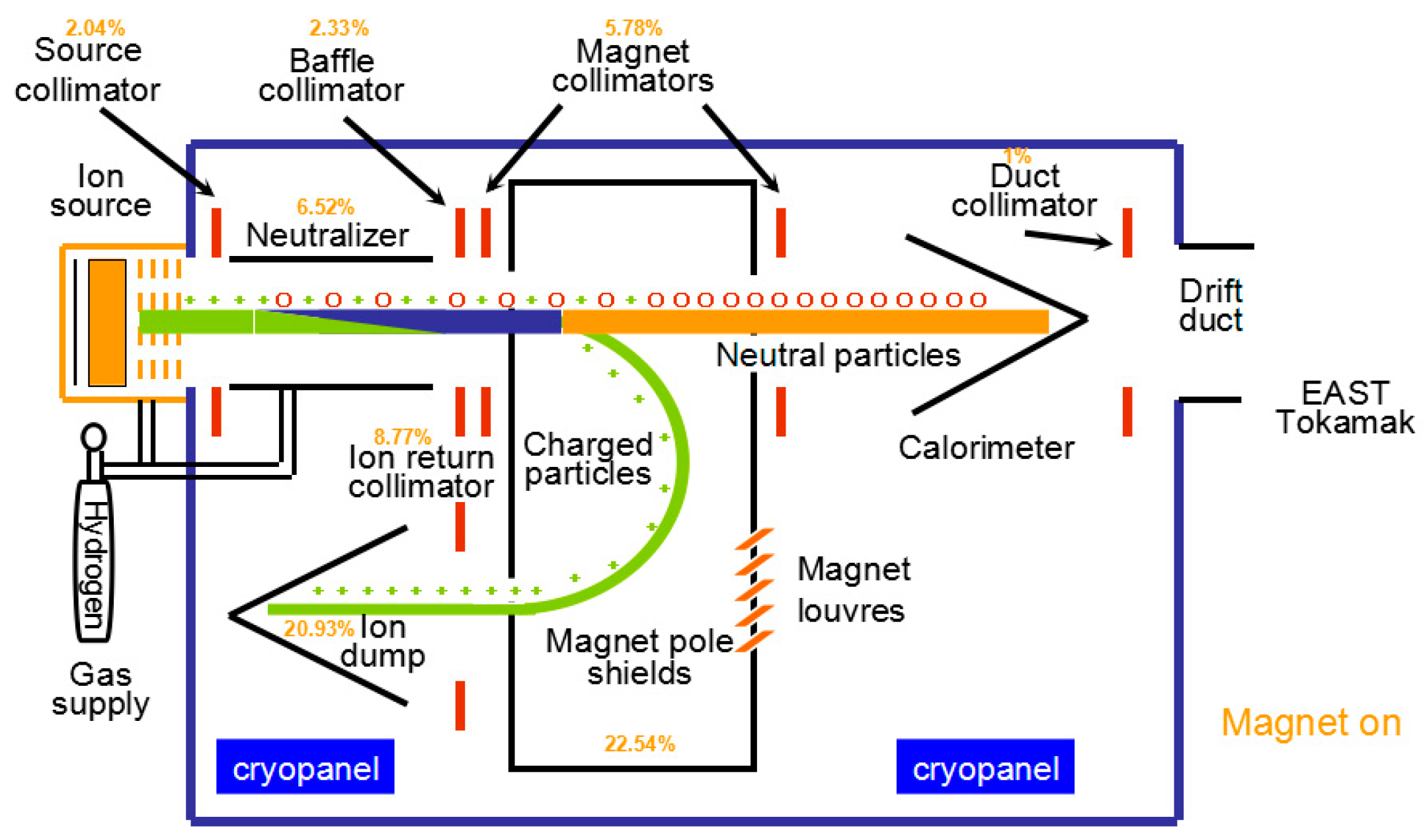
The Experimental Advanced Superconducting Tokamak (EAST) has achieve more than 100 s pulse length to maintain the plasma condition. As one of the main means of auxiliary heating and maintenance of plasma on the magnetic confinement controlled nuclear fusion experimental device [
1], Neutral Beam Injection (NBI) heating is shown in
Figure 1. The deflection magnet (DM) is one of the key components of the NBI system concerning the formation of the neutral particle beam [
2]. There are still some un-neutralized charged particles after the neutralizer, and the beam mixed with the residual ions will enter the area of the DM. The residual ions can be stripped out of the beam passage by the DM, and they then form a neutral beam that can be injected into the tokamak. According to the different sources of the force on the charged particles during deflection, the deflection methods can be divided into magnetic deflection and electrical deflection [
3,
4,
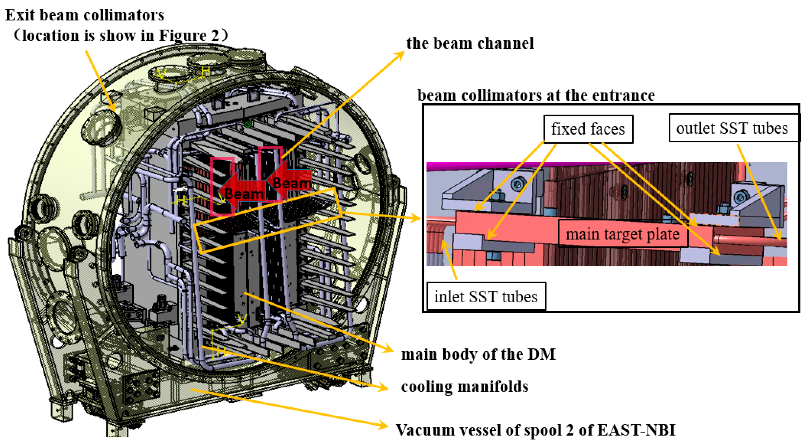
5]. Currently, the most mature and widely used is the magnetic deflection method. The EAST-NBI system also uses the magnetic deflection method, and the detail arrangement of its DM is shown in
Figure 2 [
6]; beside the body of deflection magnet yoke, it is composed of coil, magnetic pole shield, shielding bar, shutter and the entrance and exit collimators [
7]. Among those, the entrance and exit collimators are, respectively, located on both sides of the DM, and their basic function is to absorb the divergent particles of the beam to prevent them from bombarding the deflection magnet itself.
The original design of DM beam collimators adopts the inertial heat exchange mode, and the stainless steel cooling water pipe is fixed inside the copper plate by vacuum brazing, resulting in certain contact thermal resistance and a poor heat exchange effect. According to the experimental operation results of EAST-NBI (more than 65 Kev), the original design of DM beam collimators will cause the problem that the temperature rise exceeds the upper limit of the system, resulting in the suspension of the experimental operation; in the later stage of the experiment, ablation spots can be seen in parts after disassembly. Therefore, in order to improve the pulse operation time and realize the operation requirements of pulses greater than 100 s [
8] or even longer, the structure of DM beam collimators must be redesigned and optimized. Referring to the design scheme of nuclear fusion-related high heat flux components, there are many kinds of improved structure design scheme that can be used to strengthen heat exchange of collimators of DM [
9,
10,
11,
12]. In order to ensure the reliability of the structure and prevent the beam transmission from causing particle bombardment to other components, especially the cryogenic pump behind it, the beam collimators are still recommended to adopt the plate structure, according to the experience of EAST-NBI and DIII-D NBI [
13,
14]. According to the physical calculation of beam transmission characteristics, the value of the heat flux deposited on the surface of the collimators is no more than 2 MW/m
2; it is preliminarily planned to redesign the collimators as a big plate-shaped structure which is lapped to splice by some parallel-arranged small plates shaped with a straight hole inside.
Here the efficient thermo-mechanical coupling simulation method is used to optimize the new design scheme and verify its thermo-mechanical performance, which has been widely used in design and optimization of nuclear fusion-related high heat flux components [
15,
16,
17]. Wang et al. [
14] verified that the absolute collimator could better meet the design criteria of surface temperatures (<573.15 K) and a non-thermal ratcheting pulsed operation scenario by using ANSYS CFX software. Muri et al. [
18] simulated and tested the thermo-mechanical performance of 1D-carbon–carbon fiber composite prototypes for the SPIDER (Source for Production of Ion of Deuterium Extracted from RF plasma) diagnostic calorimeter. Mistry et al. [
19] evaluated the reliability of heat transfer elements (HTEs) in the worst operational condition by the thermal-structural analysis, and pointed that the second calorimeter for the Neutral Beam Indian Test Facility composed with curved V-type HTE models could meet the required number of thermal cycles (fatigue cycles) for the designed case. Wei et al. [
20] gave the thermo-mechanical design of the neutralizer for the CRAFT (Comprehensive Research Facility for Fusion Technology) negative NBI system, and obtained the appropriate combination of operating parameters. Peng et al. [
21] did steady state thermo-hydraulic and thermo-mechanical elastic analyses for the water cooled divertor of CFETR (China Fusion Engineering Test Reactor), one of the most challenging components of CFETR, to verify the feasibility of the cooling structure, and gave an optimal mass rate as a compromise between the heat load bearing and the pumping power based on analysis results. So for the new design of DM collimators, it is very important to perform the thermo-hydraulic and thermo-mechanical analysis to carry out structural optimization and obtain the optimal structure.
2. Design Scheme of New Deflection Magnet Beam Collimators
According to the area of vacuum chamber and the size of the body of deflection magnet yoke, the design size of the components left at the inlet is that: The length direction must be at least greater than 0.12 m, and the distance from the beam incoming side should be 0.36 m; that is, the restriction on the installation position of the beam and magnetic finger in the height and width directions should not be greater than 0.24 m. It is planned that the newly designed beam collimators at the DM entrance and exit will increase the heat exchange performance by using the parallel arrangement of multiple rows of tubes. The preliminary structural design is shown in
Figure 3. The exit and entrance beam collimators have a similar structure, and only the installation positions are different (shown in
Figure 2). Thus, only the entrance beam collimator is used as an example for description here and is called “beam collimator” for short. Later, combined with specific analysis and optimization, the corresponding design parameters of the two beam collimators will be given, respectively. The beam collimator is designed as a flat plate structure above the beam channel (0.12 m × 0.48 m), which can prevent the beam from transmitting to other parts. The main target plate is made of oxygen free copper, and formed by overlapping several small plates in the front and back, and the front and back of two sides of the cooper plate are arranged support structures which are fixed on the body of the DM with bolts, as shown in
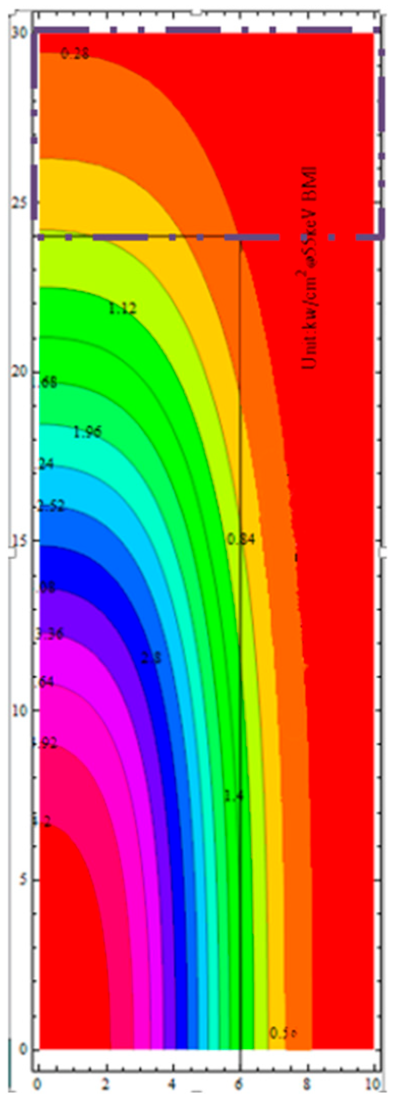
Figure 3. Considering the limitation of the space area, the main pipe can only be arranged outside the DM and the branch pipes linked with the stainless steel circular pipe to avoid the branch pipes interfering with each other, and the joint between different materials is fixed by vacuum brazing. It is required to leave about 0.007 m welding space between each two pipes. Referring to the physical analysis of beam transmission, the heat flux deposition on the entrance beam collimator is symmetrically distributed, as shown in
Figure 4 (the quarter of the whole profile).
The power deposition distribution on the collimator surface on one side of the centreline is in the dotted box. The constraints of the model optimization design are as follows: (1) The number of pipe rows is an integer. Due to the structural requirements, the value range of the pipe row diameter corresponding to a different number of pipe rows is different, but it shall be less than 0.0065 m, and the corresponding plate width of the pipe bundle shall not be less than 0.01 m; (2) the pressure drop of the tube bundle shall not be greater than 0.7 MPa; (3) the overall structural width shall not be greater than 0.136 m, and the plate thickness shall not be greater than 0.05 m; (4) the maximum temperature of the heat flow surface shall not exceed 573.15 K; in addition, the deformation of the structure shall not exceed 0.002 m, and the stress shall not exceed the required stress of oxygen free copper (plate structure) and stainless steel (branch pipe and support), which are 81 MPa and 111 MPa, respectively (with safety factor of 3).
3. Numerical Analysis Model of DM Beam Collimators
In the simulation process of the DM beam collimators, the following assumptions are used: (1) The fluid is a steady flow with constant physical properties and no internal heat source; (2) the fluid is incompressible; (3) the natural convection and thermal radiation are ignored. Considering that the structural deformation is small and the influence on fluid flow and heat transfer can be ignored, the unidirectional coupling analysis method is adopted in the numerical simulation in this paper; that is, firstly, the thermal-flow analysis model is established to calculate the transient temperature distribution and flow field pressure distribution of the collimator; on this basis, the transient structural analysis model by using the finite element method is established, and the temperature load and the fluid-structure coupling surface’s fluid pressure at each time are transmitted to the transient structural analysis model to calculate the structural deformation and stress. The thermo-hydraulic analysis model is shown in
Table 1.
Where
is fluid density, and
are the components of fluid velocity vector
in
coordinate directions, respectively.
,
and
are the components of the volume force on the micro element in the
directions.
is the dynamic viscosity of the fluid,
is the second molecular viscosity of the fluid,
is the fluid pressure,
is the fluid temperature,
is the thermal conductivity of the fluid, and
is the viscous dissipation term.
Cμ,
C1ε,
C2ε and
C3ε are model constants,
σk and
σε are the turbulent Prandtl numbers of
k and
ε equations.
Sk and
Sε are the user-defined parameters [
20,
21,
22,
23].
is the generation term of turbulent kinetic energy caused by average velocity gradient, and
is the generation term of turbulent kinetic energy caused by buoyancy.
Among them, due to the large variation of velocity in the boundary layer, more computational grids are needed to analyze the cooling pipe near the pipe wall. The resolution of the grid near the wall can be measured by the dimensionless wall distance y+.
where
is the friction velocity,
is mean velocity of fluid;
is dimensionless velocity of fluid,
is wall shear stress,
is the normal distance and
is a boundary condition and is calculated as:
Both of the friction velocities (
,
) are blended between the viscous sub-layer and the logarithmic region.
For the friction velocity
, the following formulation is used
Here, the Menter–Lechner near-wall treatment is adopted, and the main idea of the Menter–Lechner near-wall treatment is to add a source term to the transport equation of the turbulence kinetic energy k that accounts for near-wall effects. The additional source term is active only in the viscous sub-layer here. It automatically becomes zero in the logarithmic region.
In order to describe the structural vibration of the collimator, the finite element vibration model under the fluid pressure and the thermal effect is established as
where
,
and
are the global mass, damping and stiffness matrices of the collimator, respectively.
is the global nodal displacement vector and
is the global load vector (including the pressure on the fluid-structure coupling surface and the thermal stress).
Due to the different discretization methods and grid division of structural field and flow field, the grids of these two models do not match, which requires the interpolation of coupling physical quantities (the temperature and the fluid-structure coupling surface’s fluid pressure) during unidirectional coupling analysis to ensure the transmission of coupling information (such as the local interpolation represented by the mapping point method and constant volume conversion method, and the global interpolation represented by the radial basis function method).
4. Simulation and Verification of Thermo-Mechanical Performance of the New Scheme
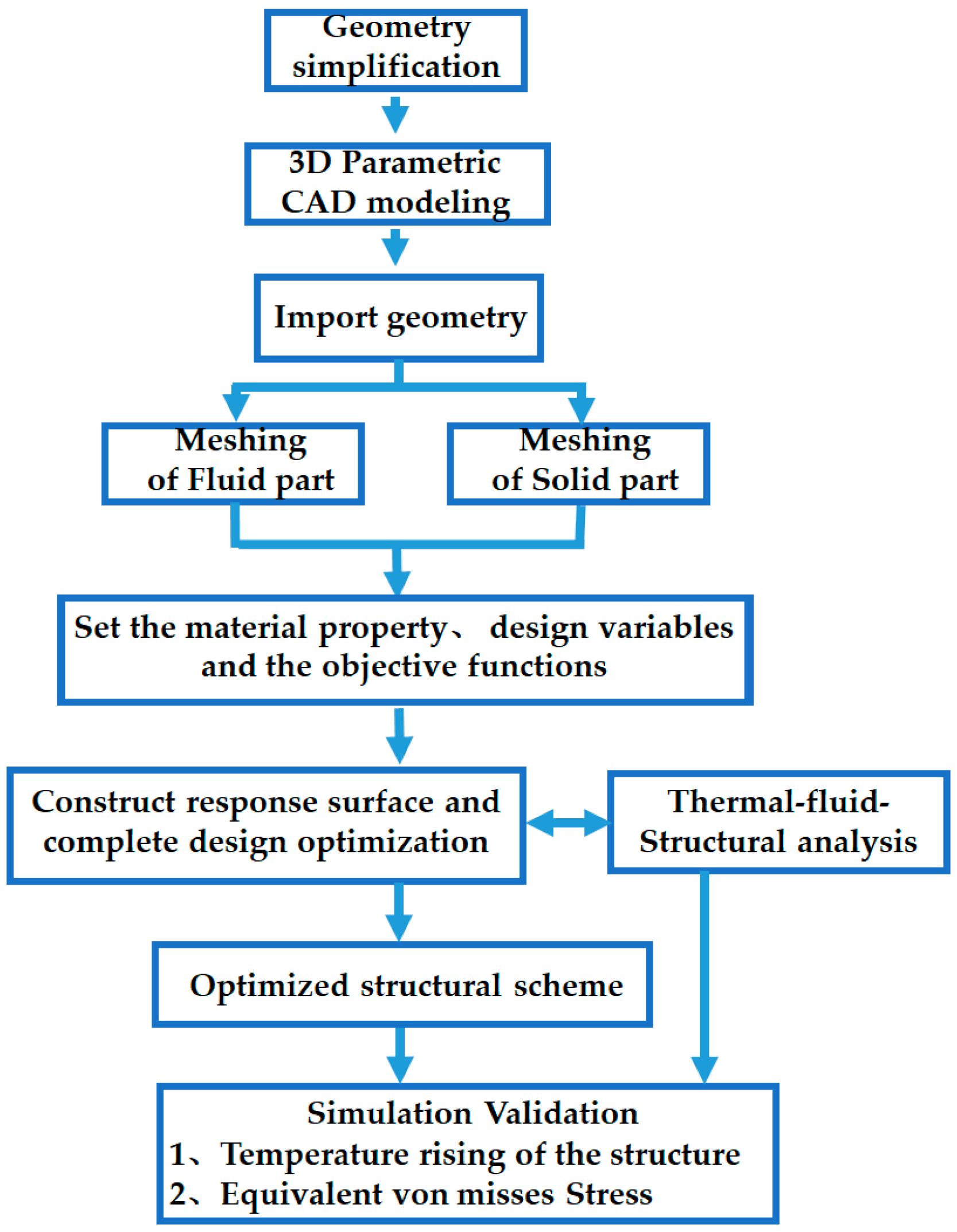
The parametric optimization method uses the sampling technology to collect the design variable sampling points, calculate the response results of each sampling point and use the quadratic difference function to construct the response surface surrogate model of the design space. Then the design optimization based on the surrogate model is completed, and the optimal design scheme is obtained. Finally, the optimal design scheme is verified by using the original thermal-fluid-structure coupling analysis model. The selection of the design parameters is mainly based on the influence on the heat exchange and cooling performance. For the design shown in
Figure 3, in order to obtain the best heat exchange performance, comprehensively considering the design constraints (1)–(4), the tube bundle diameter, the number of tube rows and the inlet flow rate are selected as the design variables. Setting the tube bundle diameter (0.0035 m, 0.004 m, 0.0045 m, 0.005 m, 0.0055 m, 0.006 m, 0.0065 m, 0.007 m and 0.0075 m), the number of tube rows as the integer value (2–10), the product of the number of tube rows and the plate width corresponding to the tube bundle diameter is less than or equal to 0.136 m (maximum design width), and the inlet flow rate is 0.1~6 m/s, respectively; different design schemes can be obtained. There are four objective functions, including the temperature rise of the heat-loaded surface, the pressure drop between the inlet and the outlet, the Von Mises stress of different parts with different materials and the space size, described in
Section 2. The corresponding analysis is carried out by using the thermal-fluid-structure coupling model described in
Section 3, and based on the parametric optimization analysis, the optimal design scheme meeting the design requirements can be obtained by comprehensively considering the engineering feasibility and economy as follows: (1) The entrance beam collimator—the minimum flow velocity is 4 m/s, and the diameter of each tube is 0.0065 m, a total of three pipes are required, the maximum spacing between each tube is 0.046 m and the diameter of the main tube is 0.011 m; (2) the outlet collimators—the minimum flow velocity is 4 m/s, the diameter of each tube is 6.5 mm, a total of four pipes are required, the maximum spacing between each tube is 0.04 m and the diameter of the main tube is 0.0127 m. The basic flow chart of simulation and optimization is shown as the
Figure 5.
For the optimized structural scheme, taking the entrance beam collimator as an example, the detailed analysis results of heat transfer performance and structural stress are given here. During the simulation process, the main part of the copper plates and the fluid areas adopt TGrid mesh, the inflated layers in the cooling pipe are set, which can make the calculation near the wall more realistic, and the Menter–Lechner near-wall treatment is chosen to describe the near-wall condition. For this optimized structure of entrance collimator, the grid independence has been verified. Under the current calculation grid state of 6.49 million, the change of surface temperature rise is about ±1 K, and the error of numerical simulation results is within 5%. The thermodynamic parameters of oxygen free copper at 293 K are as follows: The thermal conductivity is 387.6 W/m·K, the specific heat is 390 J/kg·K, the density is 8930 kg/m and the maximum surface temperature TCR = 573 K; the thermodynamic parameters of the outer stainless steel pipe are: The thermal conductivity is 16.27 W/m·K, the specific heat is 470 J/kg·K and the density is 8030 kg/m
3. Set the inlet water temperature as 293 K and the inlet flow velocity as 4 m/s. The thermodynamic parameters of the water in this state are: Specific heat of 4.183 kJ/(kg·K), density of 998.2 kg/m
3 and viscosity coefficient of 0.001006 N.s/m
2, during the simulation; the physical parameters of material are listed as shown in the
Table 2.
From
Figure 2, the entrance collimator is fixed at the inlet of DM with an inclination of about 88 degrees, the deposited heat flux value on the surface of collimator decreases and, corresponding to the vertical direction (as shown in
Figure 3), is much less than 2 MW/m
2, and the maximum value is only 1.04 mw/m
2; the approximate heat flux distribution on the corresponding surface is shown in
Figure 6. One could find that the heat flux distribution profile on the heat-loaded surface in
Figure 6 has the same trend with the beam profile as in
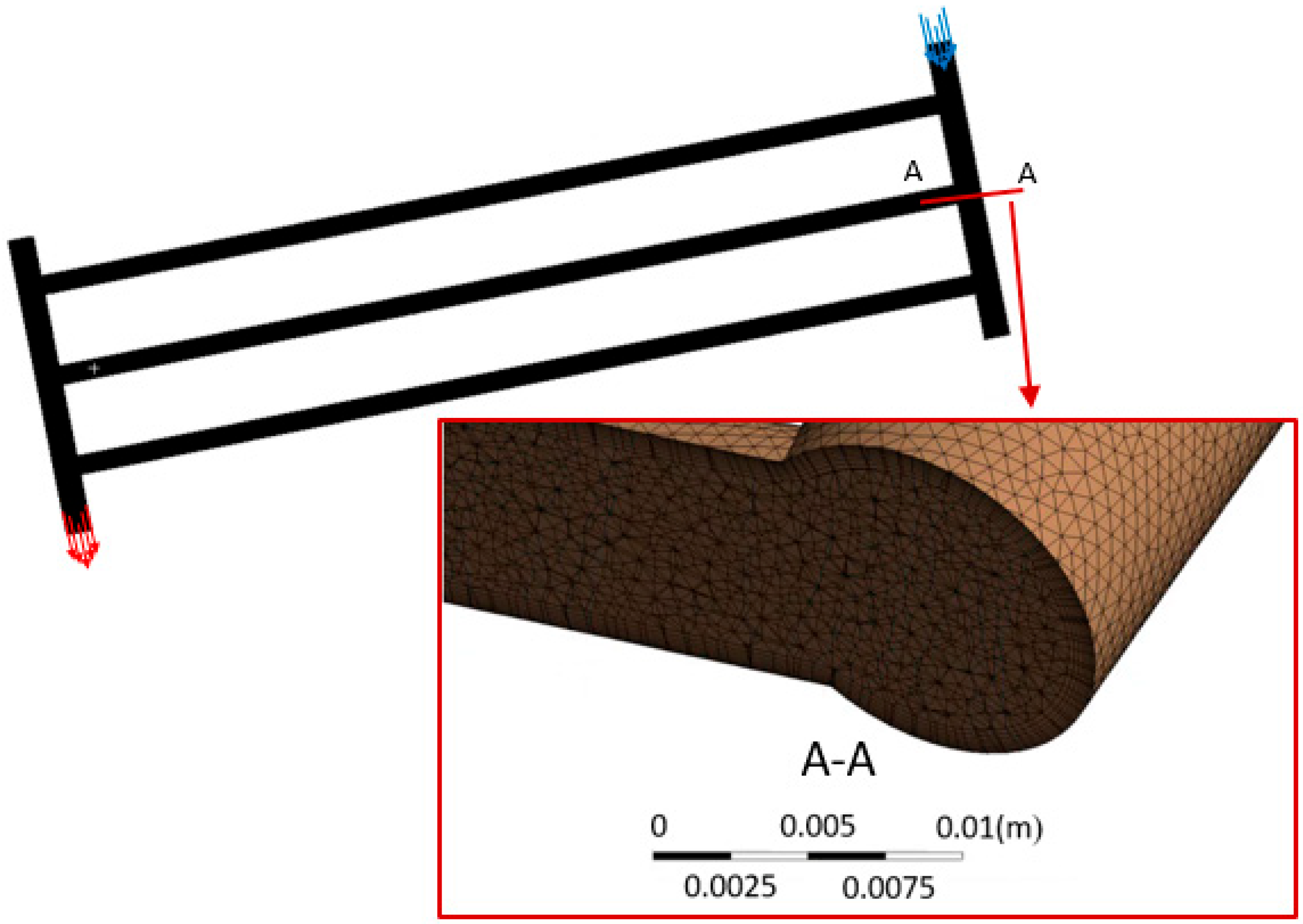
Figure 3. With an inclined angle factor, the value of heat flux density per unit area was effectively reduced, and meanwhile, there is no heat flux distribution in other locations except the loaded surface. The grid layout is shown in
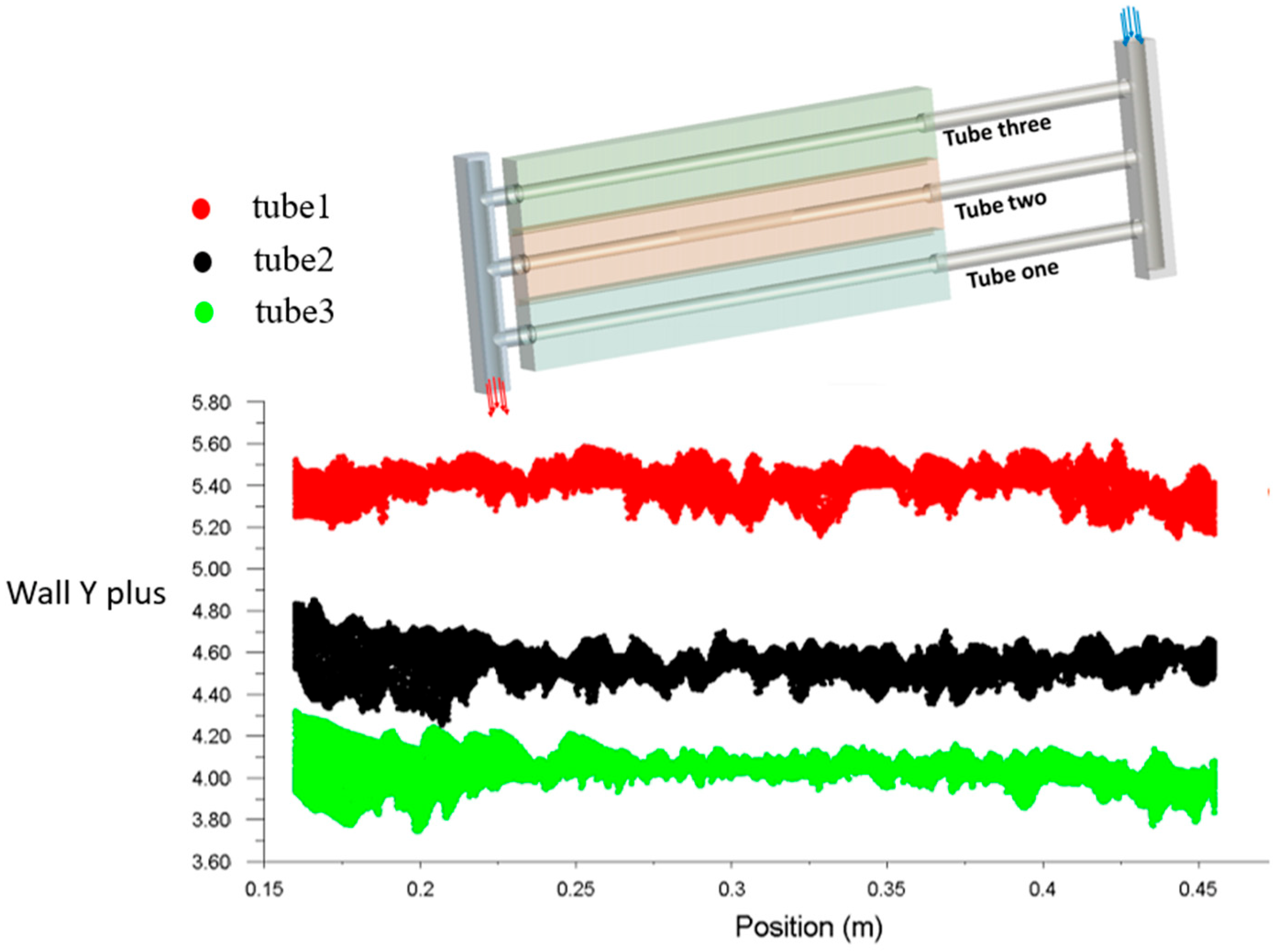
Figure 7, and the details of the boundary layer mesh where a single branch pipe joins the main pipe are shown in the enlarged view; a total of 12 boundary layers are set. The y plus varying with the length of the cooling tubes is shown in
Figure 8. The different colors in
Figure 8 represent different pipe branches from inside to outside, respectively, and three branches have different average y plus values. The total average y+ corresponding to the boundary layer is about 4~5, which meets the calculation accuracy requirements and is applicable to the current set of Menter–Lechner near-wall treatment.
The maximum temperature, flow velocity and pressure drop of the optimal design scheme for the collimator at the entrance on the above working conditions and parameters are shown in
Figure 9 and
Figure 10. In
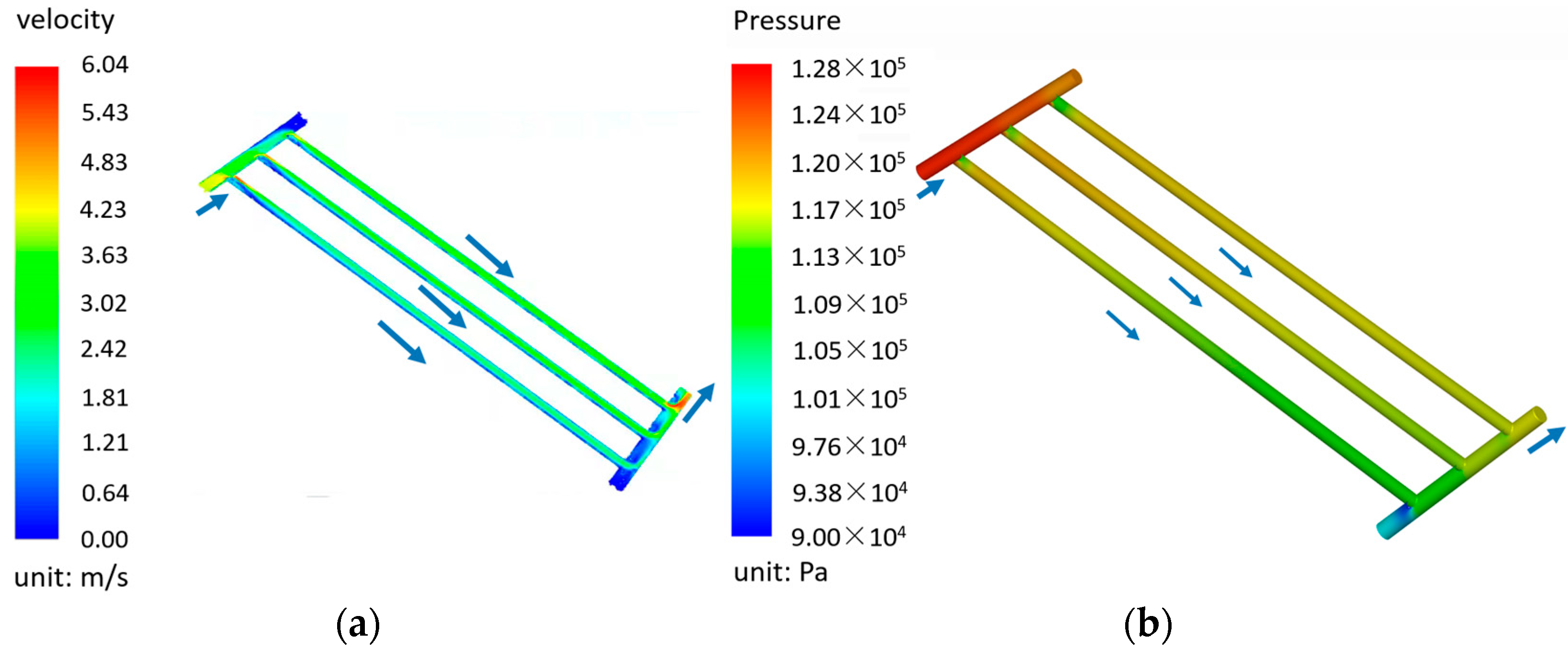
Figure 9, the maximum temperature of the heat-loaded surface increases rapidly in the first 20 s, and then the rate slows and becomes nearly steady. The maximum temperature is nearly 335 K, which means at the corresponding cooling condition, the structure has the potential to withstand a more than 100 s longer pulse bombardment. The average velocity is 3~4 m/s, and there is a rapid change of velocity at the inlet and outlet of the structure, and the maximum value of local speed (at the inlet and outlet of branch pipe) can reach 6 m/s, but in the heat exchange area, the velocity keeps quite steady, as shown in
Figure 10a. The corresponding pressure drop between the inlet and the outlet is only 0.03 MPa, as shown in
Figure 10b. The maximum velocity and pressure drop appearance is at the tube near the outlet; meanwhile, the corresponding relationship gradually increases with the distance between the cooling tubes and the inlet, which is the main feature of Z-shaped cooling tube bundles.
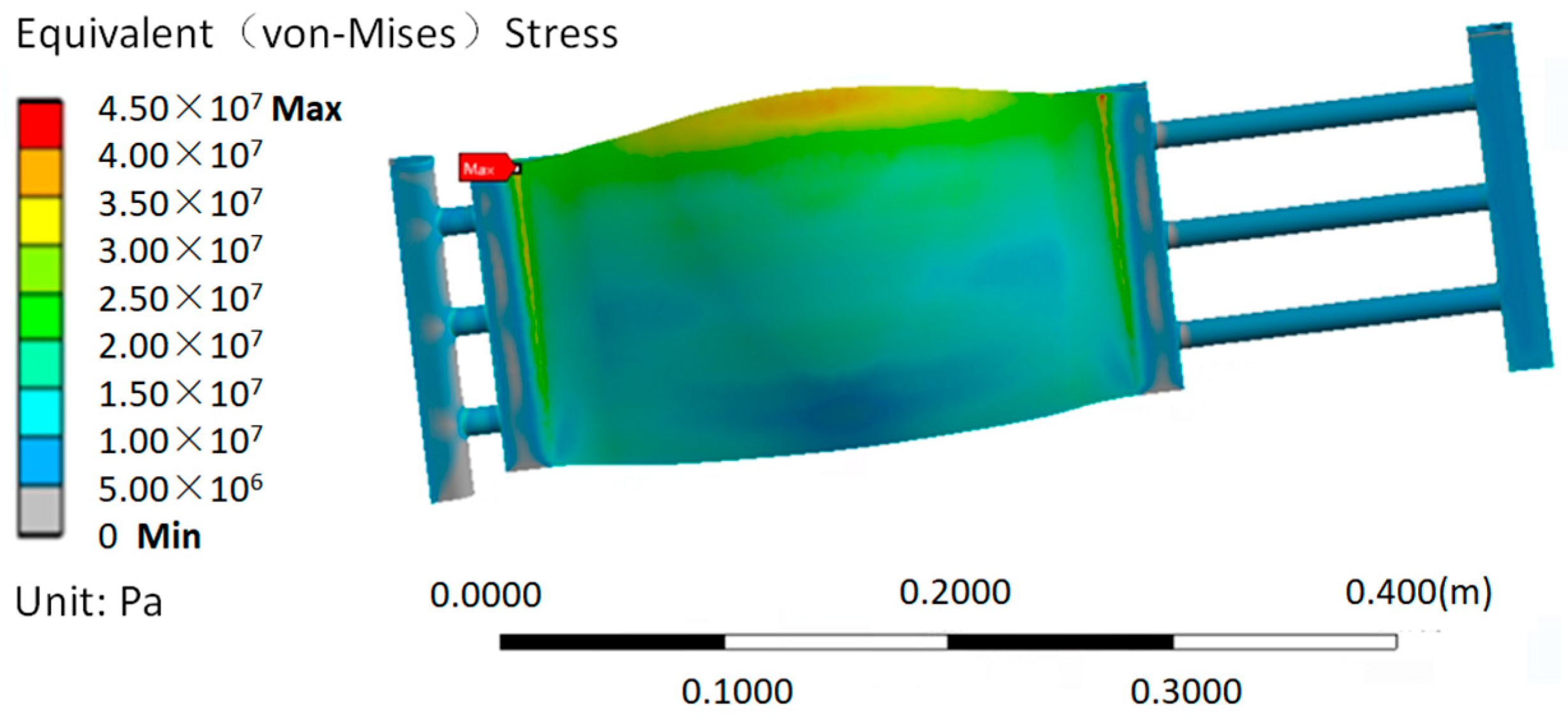
The temperature field and the structure equivalent (Von Mises) stress of entrance collimator at the 100th second are shown in
Figure 11 and
Figure 12. After the heat loaded for 100 s, the maximum temperature of the heat flux loaded surface is only 333 K; the corresponding heat transfer performance is greatly improved. The maximum structure equivalents (Von Mises) stress at the 100th second of oxygen free copper (plate structure) and stainless steel (branch pipe and support) are 45 MPa and 25 MPa, respectively, which are all less than the upper limitation. While, in the
Figure 12, it could be found that the maximum stress appears at the fixed position on both sides of the copper plate, if the heat flux continues to increase, the stress at this position will increase sharply, so in the future, if the operating heat flux exceeds more than the current working condition, the stress at this position may be more than now.
To sum up, the new entrance collimator structure can better meet the cooling requirements of the 100 s pulse length operation under the current beam operating conditions, with low surface temperature rise and low stress, and has the potential for longer pulse time operation.


