Abstract
Low-power BLDC motors are often and willingly used in many drive devices due to their functional advantages. They are also used in advanced positioning systems, where their good dynamic performance parameters are used. The control systems use shaft position sensors mounted on motors, the structure of which is based on magnetic elements and Hall sensors. The aim of this article was to investigate the influence of the BLDC motor quality on the correct operation of the control semiconductor system. The article presents the effect of BLDC motor shaft observation system’s inaccuracies on the friction and current amplitudes of individual inverter keys. Waveforms of the controller phase currents are considered and recorded on a test bench that allows precise sensor position changes. In addition, the effect of sensor misalignment on power losses in individual inverter transistors is investigated. The article shows a significant influence of the motor shaft observation system’s assembly accuracy on the current amplitudes of individual driver transistors and their power losses, which makes it necessary to consider these parameters when constructing power electronic systems.
1. Introduction
The dynamic development of the production process’s automation and the growing requirements for controllable precision has resulted in the increased number of modern electric drive systems solutions (drones, washing machines, skateboards, robotics, Industry 4.0).
The desire to reduce both the impact on the environment and the constantly growing costs of electricity isa challenge, in terms of increasing the efficiency of energy conversion through these machines. This means that, despite the high cost of permanent magnets, it is the drive systems based on this technology that are becoming dominant in the solutions created today. The increased costs of the motor’s magnetic system are partially compensated by the use of a relatively cheap solution for the shaft position observation system, based on three Hall sensors and a rotating magnet mounted on the rotor. This solution is sufficient to control BLDC motors and, with the use of shaft position estimation procedures, is also sufficient for the PMSM motor [1].
Works related to the design of the power electronic part of the drive system are often based on the use of auxiliary tools, allowing for the precise determination of the influence of individual drive system parameters and control transistors on the operation of the entire drive. This type of tool assumes the symmetry of the Hall sensor system and the rotating magnetic element. Many publications emphasize the relatively low accuracy in determining the position of the shaft by such a system, due to the imprecision of the sensor’s arrangement [2,3], as well as the execution of the rotating magnetic element itself [4]. This causes a number of problems in the operation of the drive system in a closed feedback loop, such as torque pulsations [5] or increased heating of the motor and inverter. This is because the signals from Hall sensors are used to determine the rotational speed of the motor shaft. Their asymmetrical arrangement means that, at a constant actual speed, its readings, determined on the basis of time which elapsed between successive changes in the state of the sensors, vary significantly. Additionally, the switching of the inverter transistors takes place in other than optimal conditions, which affects the efficiency of the operation of individual elements as well as the entire power electronic inverter.
As a result of these problems, a number of studies have been conducted in order to develop an effective method for the compensation of the described errors and related effects. These methods fall broadly into two groups: methods that use the measurements of electrical values (mainly currents) and correct fluctuations in the motor’s electromagnetic torque, and methods that calculate the sensor placement errors based on the time elapsed between successive steady-state commutation points of transistors. Methods that limit current fluctuations reduce the asymmetry of its amplitude between phases, but mostly do not affect the duration of the commutation signal—hence, the losses between different legs will still be different, and the power switches will heat up to different temperatures. Methods that focus on modifying transistor switching times also have disadvantages. The first is the need to synchronize the calculated transistor switching signal with one of the Hall sensors. This procedure is relatively simple for motors with one pair of poles, or when the rotating magnet on the motor shaft is made perfectly symmetrically. However, the asymmetry of the magnet, which is a common phenomenon [6], causes the intervals between successive commutation points of transistors for multipole motors to be different, despite the same state of the Hall sensors. This significantly complicates the process of calculating the commutation errors and assigning them to individual sectors of the winding operation. The compensation of the sensor placement and the rotating element inaccuracies places high demands on the inverter control systems and are reserved for the most advanced control systems. Their action positively affects the operation of the closed-loop system by correcting speed readings, but often does not focus on improving transistor commutation.
One of the hybrid methods of torque pulsation compensation is described in [7]. It utilizes the fact that, by deriving the relationship between three-phase currents and error angles, one can obtain the Hall sensor’s installation error angle. First, it is determined whether a particular sensor is operating with a delay or an advance. This is detected by observing the phase current at the rising edge of the corresponding Hall sensor. For a delayed Hall sensor signal, the current will be greater than the stable current. The optimum delay angle for the next electrical cycle is then determined, thus reducing torque ripple and commutation time. Among the placement error compensation methods, there are also those based on calculating sector interval and signal errors, and then compensating them [8]. The authors in [8] also present a novel PWM signal generation scheme using compensated Hall signals. Another method of rotor position determination is the one described in [9]. It consists of transforming the Hall vector to an alpha-beta vector with fundamental and harmonic waves, and then applying frequency filtering. This approach leads to a reduction in torque ripple as well as a decreased power loss in the inverter; however, the authors of the paper do not show the values by which the power losses were reduced. The methods based on data analysis also include the method described in [10] of averaging the errors for a given speed to eliminate the influence of steady-state errors, assuming that at least one of the Hall sensors is installed correctly. The proposed method also reduces the heating of the inverter DC bus capacitor.
The correct operation of inverters depends mainly on their topology but also on the control method. Hence, more and more works aim to optimize the inverters used in electric drive, grid [11,12], renewable energy [13], and electromobility [14,15] applications. The damage possibility caused by excessive heating of the device [16] has also led to the development of numerous techniques to estimate the temperature of both BLDC motors [17] and semiconductor junctions of transistors. These activities are largely focused on the implementation of modern equipment maintenance techniques and the detection of anomalies in their operation.
2. Hall Sensors Misalignment
The error in the arrangement of sensors is a common problem in BLDC motors [18]. Many researchers in this field point out the error of reading the engine speed as a function of changes in the state of the shaft position sensors over time. Hall sensor misalignment makes the time intervals between successive changes in the state of the Hall sensors different at a constant, real engine speed, introducing errors in determining the rotor speed. These errors often reach several dozen percent, preventing the implementation of a fast speed feedback loop and causing pulsations of the electromagnetic torque, significantly affecting the operation of the BLDC motor [19,20,21]. These difficulties are multiplied by the accuracy of the manufacturing for the rotating magnetic element mounted on the machine shaft.
The problems related to the accuracy of determining the position of the motor shaft are not limited to the deterioration of the closed-loop speed feedback of the motor. Since the change in the state of Hall sensors is a signal for the control system to modify the generated voltage vector, its change in the non-optimal position of the rotor () in relation to the stator is associated with the flow of greater current through the power electronic switch. This is because, when the transistor is turned on at a non-optimal moment intime, the rotating rotor with permanent magnets induces too low a voltage in the stator winding. This is a situation comparable to a temporary reduction in the rotor flux of a motor. These dependencies result directly from the mathematical model of the electric BLDC motor [22,23].
For simplification, the electrical model is expressed for one phase of the stator windings, as shown below.
where
- is the k-phase voltage,
- is the k-phase current,
- is the k-phase back EMF voltage,
- is the resistance of each stator winding,
- is the inductance of each stator winding,
- is the number of turns of wire,
- ΦB is the magnetic flux through a single loop.
This effect has a large impact on the value of the currents flowing through the inverter transistors, especially since the asymmetry causes a cyclical increase in the current amplitude of individual transistors and may lead to their uneven heating. In extreme cases, it may damage the transistor, and thus stop the operation of the entire device.
3. BLDC 3-Phase Inverter Modelling
BLDC motors, like all three-phase motors, use an inverter topology based on a system of six semiconductor switches operating in a three-phase bridge system. It assumes the use of power switches with the same parameters and a symmetrical flow of the phase currents of the electric machine powered in this way.
Among the BLDC motors’ control methods, the most frequently used method is the block commutation method [24]. Such commutation methods include bipolar, unipolar, six step commutation [25] and hybrid dead-time methods [26]. The six-step unipolar method was used for the tests. It is characterized by the fact that only the upper transistors of each leg of the inverter are switched with the PWM signal, while the lower transistors are used to close the circuit of the motor phase currents [27]. A characteristic feature of this method of control is that the three transistors in the upper part of the bridge work are completely differently to the lower transistors (Figure 1). Their switching losses are significantly greater and more proportional to their switching frequencies [27,28]. The losses of the lower transistors depend mainly on the body diode parameters. Importantly, the total losses of the converter are also influenced by the static and dynamic parameters of the transistors and their type [29].
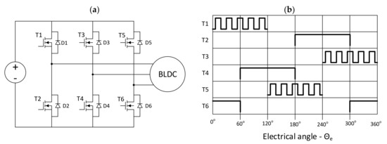
Figure 1.
Circuit (a) control method and (b) BLDC motor transistors according to six step asynchronous PWM strategy.
Unipolar asynchronous PWM is the simplest BLDC motor control algorithm which, at the same time, is characterized by slightly increased losses compared to the bipolar method. Due to its popularity and increased losses compared to other methods, it was selected to control the inverter transistors on the test stand.
4. Experimental Research
In order to determine the influence of the BLDC motor’s Hall sensors’ placement inaccuracy on the operation and losses of the three-phase inverter, experimental studies were performed. The block diagram of the measurement system is presented in Figure 2a. A prototype laboratory measurement setup is shown in Figure 2b. It consists of an inverter based on the Mosfet Infineon IPW65C7045 transistors (Table 1), which feeds the FXD57BL BLDC motor with a power of P = 150W and a rated voltage of U = 24 VDC (Table 2). This motor is connected using a dog coupling to an auxiliary machine working as a generator loaded with a resistor. The control algorithm is implemented in the 32-bit microcontroller of the STM32F302 series. The measuring part of the laboratory stand consists of a Tektronix DPO5054B oscilloscope equipped with TCP0030A, THDP0200 measuring probes, a Keithley DMM6500 multimeter, a RND320 laboratory power supply, a DMT21 tachometer, and an FLIR6500 thermal imaging camera.
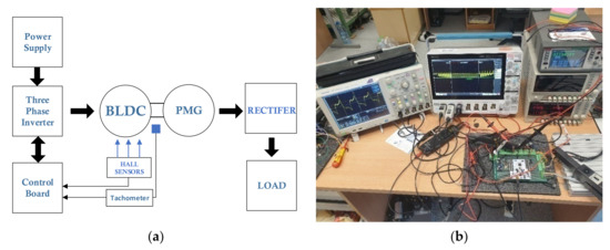
Figure 2.
(a) Block diagram of the measuring system; (b) laboratory setup.

Table 1.
IPW65C7045 parameters.

Table 2.
BLDC motor parameters.
During the research, it is necessary to enable the Hall sensors’ position to be changed with high accuracy and repeatability, so their adjustment by means of physical position manipulation is difficult. It is especially difficult with the assumed accuracy of one electric degree which, with a motor with two pole pairs, translates into the position changing accuracy of the sensor by a 0.5 mechanical degree. It was decided upon to use a 14-bit absolute encoder system, which allows the commutation angle to be adjusted with an accuracy of (for the number of pole pairs of the tested motor p = 2):
The controller cyclically reads the values of the rotor shaft absolute position and switches the control system for the commutation angles saved in the device’s memory. These angles can be changed by the user while the drive is running.
4.1. Conditions of Conducted Experimental Research
The test procedure was carried out using the following basic operating conditions: constant, nominal torque; a constant rotational speed of n = 1100 rpm; PWM switching frequency of f = 10 kHz; and supply voltage of Udc = 24V.
The values of power losses in the inverter in relation to the sensor arrangement error were determined while maintaining a constant rotational speed and a constant load torque. By modifying the parameters of the control system, the transistor’s commutation point was shifted as if the Hall B sensor’s position changed every 1 mechanical degree in the range (1–20)° while taking measurements. The power losses in the inverter transistors were determined for each transistor separately on the basis of the values of currents and voltages measured by the circuit shown in the picture (Figure 3) using the advanced power analysis option of the Tektronix DPO5054B oscilloscope (Tektronix DPO-PWR (power measurement and analysis)) (Figure 3). The above test procedure helps to reproduce the actual conditions of continuous operation of the engine and enables the determination of losses in the inverter’s semiconductors in the steady state condition with the load torque and rotational speed unchanged. In addition, the measurement method (Figure 3) helps to determine the RMS value and the current amplitude separately in each inverter transistor, and thus allows for the precise determination of their power losses.
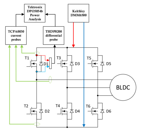
Figure 3.
Laboratory measurement setup.
When performing the power loss measurements of inverter transistors, the key aspect is the quality of the measurement probes and their correct calibration. A particularly important aspect is the phase shift between the signal from the voltage probe and the current probe. This shift should be minimized by configuring the “deskew” parameter in the Tektronix oscilloscope during the probe calibration procedure. Such a procedure was carried out with reference to [30] by Tektronix and using a circuit with a low-impedance measurement resistor and a rectangular waveform generator, similar to the Power Measurement Deskew Fixture system by Tektronix. After such calibration, the measurements on the test bench were carried out.
4.2. Experimental Results
The results of the laboratory tests are presented below. Figure 4 shows the results of experimental research on power losses and the values of effective phase currents as a function of the shift angle of the Hall B sensor. Figure 4a shows a diagram of power losses in the upper transistors of the inverter. It can be observed that the power losses in the upper phase U and V transistors in the range (0–10)° increase linearly, while this relationship becomes exponential in the range (11+)°. For an exemplary shift of the sensor by 20° from the optimal position, the increase in the value of power losses is 700 mW, which gives a change of 43%. It is worth noting that the increase in power losses occurs only in the U and V phases, while the power losses change insignificantly in the W phase. Figure 4b shows that the power losses in the lower transistors of the inverter have a similar waveform. These values also include body diode losses, which are strongly related to the transistor parameters.
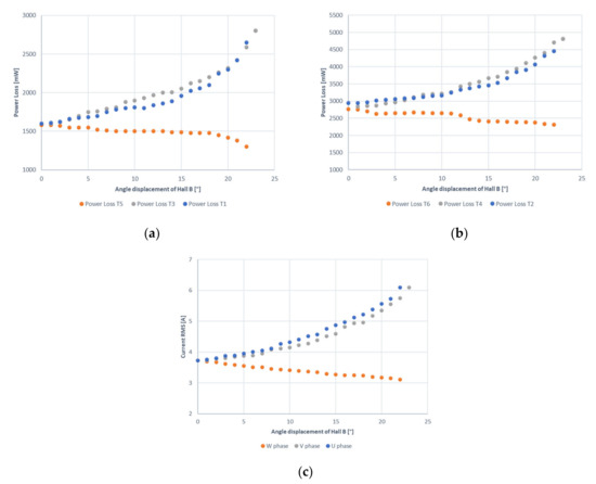
Figure 4.
Experimental results as a function of angle displacement of Hall B sensor: (a) power loss in the high-side switch; (b) power loss in the low-side switch (include body diode loss); (c) RMS phase currents.
Figure 4c shows the change in the value of the root mean square phase currents of the inverter in relation to the sensor shift angle. For the original position of the sensor, the RMS values of the phase currents are equal to 3.7 A. As the shift angle increases in the U and V phases, the RMS current begins to increase to 6 A for (22° shift), while this current begins to linearly decrease to the value of 3.1 A at a 22° displacement in the W phase. This is due to the reduced turn-on time of the W phase transistors that results from the delayed triggering of Hall B (Figure 8). The recorded waveforms of the motor phase currents for different angles of the Hall B offset from the optimal position are shown in Figure 5.
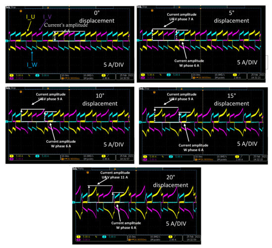
Figure 5.
Phase currents waveforms depending on Hall B sensor displacement.
On the basis of the measurement oscillograms, it can be seen that with the increased shift angle, the amplitudes of the U and V phase currents also increase from 6 A to 11 A for a 20° shift, while the current amplitude remains unchanged in the W phase. Along with the increase in the phase currents asymmetry, the noise emitted by the drive functioning in this way and the fluctuations of the electromagnetic moment increase.
Figure 6 shows an oscillogram from the measurements of the upper and lower currents of the transistors in a given branch. On this basis, effective values, maximum currents, and power losses in individual transistors were determined.
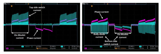
Figure 6.
Top- and high-side switchcurrent waveform from experimental research.
Figure 7 shows the distribution of individual types of power losses (conduction, switching, diodes) in the inverter transistors in relation to the sensor shift angle with the block control method. Conduction and switching loss dominate in the group of top-side switches (T1, T3, T5). On the other hand, in the group of bottom-side switches (T2, T4, T6), there are mainly syn diode and conduction losses. It can be noticed that, with the increased shift angle of the Hall B sensor, the load distribution on individual power switches changes, causing an unbalance in the inverter load. In transistors (T1, T2, T3, T4), the total power losses start to increase, while they decrease in (T5, T6). In the second branch (T2, T4), the power losses increase from 1600 mW to 2400 mW for the T2 switch, and from 2800 mW to 4200 mW for the T4 switch, which means an increase of 50%. This causes a change in the distribution and a strong difference in the temperature increase of individual transistors.
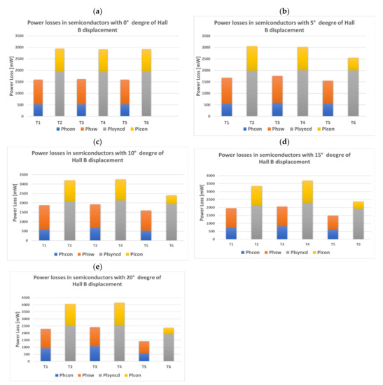
Figure 7.
Top- and high-side switches division power loss of experimental results in the function of Hall B displacement: (a) 0 deg; (b) 5 deg; (c) 10 deg; (d) 15 deg; (e) 20 deg.
Changing the position of the sensor increases the power losses on the transistors switched at a non-optimal moment of the rotor position in relation to the winding, but also makes the switches carrying the increased current work for longer (Figure 8). This additionally worsens the heat balance of the inverter transistors and makes it necessary to modify the method of determining the converter losses.
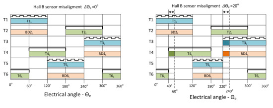
Figure 8.
Losses in individual elements of the unipolar-controlled BLDC motor inverter as a function of the electric angle, TXL—transistor X losses, BDXL—body diode losses of TX transistor.
Assuming a symmetrical distribution of sensors, the power losses in the entire semiconductor system are determined by summing the power losses of individual elements [31,32] and dividing the obtained value by three [33]. This is because unipolar asynchronous PWM is a control method in which each switch only works for one third of the inverter operating time.
The system with asymmetry in the Hall sensors’ arrangement should be treated completely differently. Apart from the changes related to the increase in effective currents flowing through power transistors, it is necessary to take into account the different working duration of individual switches involved in the commutation of the system. The negative effect of the HallB sensor asymmetry is not only the increased effective current for T3 and T4 transistors, but also the extension of their operation time in relation to other switches. This causes an additional increase in the energy released on the half-bridge elements and a further increase in the T3 and T4 temperature.
As the losses on individual components increase, the losses of the inverter as a whole increase. The results of the total inverter losses as a function of the HallB sensor placement error are shown in Figure 9.
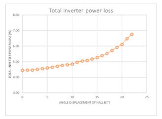
Figure 9.
Total losses of the inverter transistor connectors as a function of the Hall B sensor shift from the optimal axis.
In order to verify the influence of the sensor arrangement asymmetry on the temperature of semiconductor switches, load tests were carried out with the rated torque for five values of the shift angle of the Hall B sensor (0.5, 10, 15, 20)°. Each of the tests lasted 10 min and were performed with a constant load moment. Before each subsequent test, the BLDC motor and the inverter were cooled down to the ambient temperature. The non-optimal positions of the Hall B sensor resulted in increased losses in the bridge. consisting of T3 and T4 transistors. In T4, there are additional losses related to the current flow through the body diode; therefore, the temperature measurement focus point is on transistor T4.
With the correct arrangement of the sensors, where the losses are evenly distributed between the inverter branches, the temperature of the T4 transistor is 54.2 degrees and increases to 95 degrees when Hall B sensor displacement equals 20° (Figure 10). The operation of the transistor at such a temperature without an appropriate cooling system increases the power losses and additionally worsens its parameters (e.g., it increases the RDS(ON)), which may result in permanent semiconductor damage.
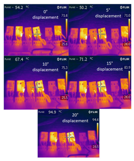
Figure 10.
Image of the temperature distribution of the inverter transistors for different Hall B offsets.
5. Conclusions
Inaccurate placement of the sensors leads to increased losses and an asymmetric increase in the inverter transistor’s current. Their unbalanced load causes some transistors to heat up much more than others. With serious errors in the placement of sensors, the phase current amplitude can increase significantly—even by 40% (Figure 4c), while extending the working time of the transistor. This significantly increases the thermal power dissipated on the transistor and total power losses of the inverter (Figure 9). As this effect is observed over the entire range of engine speeds and load torques, it can lead to their overheating and, consequently, damage. The conducted tests clearly indicate the need to consider the presence of the inaccuracies in the shaft position observation system when designing the BLDC motor inverter. In addition to the negative impact on the hardware part of the converter, significant differences in phase currents may have a negative impact on the operation of the current and speed controller. Based on the conducted research, we can conclude that small inaccuracies of sensor placement <2.5°are acceptable and do not cause significant asymmetry of the motor phase currents. In the case of larger inaccuracies (which is a typical problem in low-power BLDC motors [6]), it is necessary to take this fact into account when selecting inverter elements. A good solution may be the use of advanced software methods in sensor placement error correction. These methods correct the asymmetry of signals that control the switching of the inverter transistors. Typical commercial drive systems rarely use them. These are very often based on off-the-shelf circuits that control transistor switches depending on the Hall sensor state and are not equipped with any computational logic capable of correcting sensor placement inaccuracies. This is why it is so important for drive system designers to be aware that the quality of the shaft position observation system design has a significant impact. The selection of inverter elements must be correlated with the measuring system quality in order to prevent damage to transistor switches while maintaining high efficiency of the drive system.
Author Contributions
Conceptualization, K.K. and B.D.; methodology, A.J.M.; software, J.G. and B.D.; validation, A.J.M., B.D. and K.K.; formal analysis, A.J.M.; investigation, B.D. and K.K.; resources, J.G.; data curation, B.D.; writing—original draft preparation, K.K. and B.D.; writing—review and editing, A.J.M.; visualization, J.G. and B.D.; supervision, A.J.M.; project administration, K.K.; funding acquisition, K.K. All authors have read and agreed to the published version of the manuscript.
Funding
This work was supported by Lublin University of Technology grant no.FD-20/EE-2/605.
Institutional Review Board Statement
Not applicable.
Informed Consent Statement
Not applicable.
Data Availability Statement
Not applicable.
Conflicts of Interest
The authors declare no conflict of interest.
References
- Giulii Capponi, F.; De Donato, G.; Del Ferraro, L.; Honorati, O.; Harke, M.C.; Lorenz, R.D. AC Brushless Drive with Low-Resolution Hall-Effect Sensors for Surface-Mounted PM Machines. IEEE Trans. Ind. Appl. 2006, 42, 526–535. [Google Scholar] [CrossRef]
- Alaeinovin, P.; Jatskevich, J. Filtering of Hall-Sensor Signals for Improved Operation of Brushless DC Motors. IEEE Trans. Energy Convers. 2012, 27, 547–549. [Google Scholar] [CrossRef]
- Park, J.-W.; Kim, J.-H.; Kim, J.-M. Position Correction Method for Misaligned Hall-Effect Sensor of BLDC Motor using BACK-EMF Estimation. Trans. Korean Inst. Power Electron. 2012, 17, 246–251. [Google Scholar] [CrossRef][Green Version]
- Mahdiuon-Rad, S.; Mousavi-Aghdam, S.R.; Reza Feyzi, M.; Sharifian, M.B.B. Analysis of PM Magnetization Field Effects on the Unbalanced Magnetic Forces Due to Rotor Eccentricity in BLDC Motors. Eng. Technol. Appl. Sci. Res. 2013, 3, 461–466. [Google Scholar] [CrossRef]
- Kolano, K.; Drzymała, B.; Gęca, J. Sinusoidal Control of a Brushless DC Motor with Misalignment of Hall Sensors. Energies 2021, 14, 3845. [Google Scholar] [CrossRef]
- Kolano, K. Determining the Position of the Brushless DC Motor Rotor. Energies 2020, 13, 1607. [Google Scholar] [CrossRef]
- Xuliang, Y.; Xiaoming, J.; Yan, Z. Compensation Method for Commutation Torque Ripple Reduction of BLDC Motor with Misaligned Hall Sensors. In Proceedings of the IECON 2017—43rd Annual Conference of the IEEE Industrial Electronics Society, Beijing, China, 29 October–1 November 2017; pp. 1862–1867. [Google Scholar]
- Wang, L.; Zhu, Z.Q.; Bin, H.; Gong, L.M. A Commutation Optimization Strategy for High Speed Brushless DC Drives with Inaccurate Rotor Position Signals. In Proceedings of the 2021 Sixteenth International Conference on Ecological Vehicles and Renewable Energies (EVER), Monte-Carlo, Monaco, 5–7 May 2021; pp. 1–9. [Google Scholar]
- Lim, J.-H.; Park, S.M.; Hyon, B.J.; Park, J.S.; Kim, J.-H.; Choi, J.-H. Study on PMSM Rotor Position Compensation Method for Hall-Effect Sensor Installation Error Using WBG- Based Inverter. In Proceedings of the 2021 24th International Conference on Electrical Machines and Systems (ICEMS), Gyeongju, Korea, 31 October–3 November 2021; pp. 1844–1848. [Google Scholar]
- Liu, S.; Liu, Y.; Zhang, H. A Data-Based HALL Sensor Position Deviation Compensation Method. In Proceedings of the 2021 IEEE 4th International Electrical and Energy Conference (CIEEC), Wuhan, China, 28–30 May 2021; pp. 1–6. [Google Scholar]
- Jarzyna, W.; Zieliński, D.; Gopakumar, K. An Evaluation of the Accuracy of Inverter Sync Angle During the Grid’s Disturbances. Metrol. Meas. Syst. 2020, 27, 355–371. [Google Scholar] [CrossRef]
- Jarzyna, W.; Zieliński, D.; Zielińska, K.; Fatyga, K. Reduction of Voltage and Power Oscillation in the Two-Phase Shorting of a Grid Inverter. In Proceedings of the 2017 19th European Conference on Power Electronics and Applications (EPE’17 ECCE Europe), Warsaw, Poland, 11–14 September 2017; pp. 1–8. [Google Scholar] [CrossRef]
- Ahmed, M.H.; Wang, M.; Hassan, M.A.S.; Ullah, I. Power Loss Model and Efficiency Analysis of Three-Phase Inverter Based on SiC MOSFETs for PV Applications. IEEE Access 2019, 7, 75768–75781. [Google Scholar] [CrossRef]
- Subrahmanya Kumar Bhajana, V.V.; Jarzyna, W.; Fatyga, K.; Zieliński, D.; Kwaśny, Ł. Performance of a Sic Mosfet Based Isolated Dual Active Bridge DC-DC Converter for Electro-Mobility Applications. Rev. Roum. Sci. Tech. Série Électrotech. Énergétique 2019, 64, 383–390. [Google Scholar]
- Fatyga, K.; Zieliński, D. Comparison of Main Control Strategies for DC/DC Stage of Bidirectional Vehicle Charger. In Proceedings of the 2017 International Symposium on Electrical Machines (SME), Naleczow, Poland, 18–21 June 2017; pp. 1–4. [Google Scholar]
- Kudelina, K.; Asad, B.; Vaimann, T.; Rassõlkin, A.; Kallaste, A.; Khang, H.V. Methods of Condition Monitoring and Fault Detection for Electrical Machines. Energies 2021, 14, 7459. [Google Scholar] [CrossRef]
- Czerwiński, D.; Gęca, J.; Kolano, K. Machine Learning for Sensorless Temperature Estimation of a BLDC Motor. Sensors 2021, 21, 4655. [Google Scholar] [CrossRef] [PubMed]
- Beccue, P.B.; Pekarek, S.D.; Deken, B.J.; Koenig, A.C. Compensation for Asymmetries and Misalignment in a Hall-Effect Position Observer Used in PMSM Torque-Ripple Control. IEEE Trans. Ind. Appl. 2007, 43, 560–570. [Google Scholar] [CrossRef]
- Tsotoulidis, S.; Safacas, A. Side-Effects of Hall Sensors Misplacement on BLDC Motor Drive Operation. In Proceedings of the 2014 International Conference on Electrical Machines (ICEM), Berlin, Germany, 2–5 September 2014; pp. 1825–1830. [Google Scholar]
- Samoylenko, N.; Han, Q.; Jatskevich, J. Dynamic Performance of Brushless DC Motors With Unbalanced Hall Sensors. IEEE Trans. Energy Convers. 2008, 23, 752–763. [Google Scholar] [CrossRef]
- Alaeinovin, P.; Chiniforoosh, S.; Jatskevich, J. Evaluating Misalignment of Hall Sensors in Brushless DC Motors. In Proceedings of the 2008 IEEE Canada Electric Power Conference, Vancouver, BC, Canada, 6–7 October 2008; pp. 1–6. [Google Scholar]
- Tan, B.; Wang, X.; Zhao, D.; Shen, K.; Zhao, J.; Ding, X. A Lag Angle Compensation Strategy of Phase Current for High-Speed BLDC Motors. IEEE Access 2019, 7, 9566–9574. [Google Scholar] [CrossRef]
- Lee, A.-C.; Fan, C.-J.; Chen, G.-H. Current Integral Method for Fine Commutation Tuning of Sensorless Brushless DC Motor. IEEE Trans. Power Electron. 2017, 32, 9249–9266. [Google Scholar] [CrossRef]
- Lai, Y.; Lin, Y. Assessment of Pulse-Width Modulation Techniques for Brushless DC Motor Drives. In Proceedings of the Conference Record of the 2006 IEEE Industry Applications Conference Forty-First IAS Annual Meeting, Tampa, FL, USA, 8–12 October 2006; Volume 4, pp. 1629–1636. [Google Scholar]
- Ciurys, M.P. Analysis of the influence of inverter PWM speed control methods on the operation of a BLDC motor. Arch. Electr. Eng. 2018, 67, 939–953. [Google Scholar] [CrossRef]
- Kim, H.-J.; Park, H.-S.; Kim, J.-M. Expansion of Operating Speed Range of High-Speed BLDC Motor Using Hybrid PWM Switching Method Considering Dead Time. Energies 2020, 13, 5212. [Google Scholar] [CrossRef]
- Hossain, S.A.; Reis, P. Effect of BLDC Motor Commutation Schemes on Inverter Power Loss. In Proceedings of the 2008 18th International Conference on Electrical Machines, Vilamoura, Portugal, 6–9 September 2008; pp. 1–5. [Google Scholar]
- Miyamasu, M.; Akatsu, K. Efficiency Comparison between Brushless DC Motor and Brushless AC Motor Considering Driving Method and Machine Design. IEEJ J. Ind. Appl. 2013, 2, 79–86. [Google Scholar] [CrossRef]
- Schonewille, K.R. Efficiency Comparison between Si and GaN Based Triple Half Bridge BLDC Motor Drivers. Bachelor’s Thesis, University of Twente, Enschede, The Netherlands, 2020. [Google Scholar]
- Measuring Power Supply Switching Loss with an Oscilloscope. Available online: https://www.tek.com/en/documents/application-note/measuring-power-supply-switching-loss-oscilloscope (accessed on 16 February 2022).
- Kolar, J.W. Losses in PWM Inverters Using IGBTs. IEE Proc.-Electr. Power Appl. 1995, 142, 285. [Google Scholar] [CrossRef]
- Acquaviva, A.; Rodionov, A.; Kersten, A.; Thiringer, T.; Liu, Y. Analytical Conduction Loss Calculation of a MOSFET Three-Phase Inverter Accounting for the Reverse Conduction and the Blanking Time. IEEE Trans. Ind. Electron. 2021, 68, 6682–6691. [Google Scholar] [CrossRef]
- Neaca, M.I.; Neaca, A.M. Determination of Power Loss in Inverters Which Supply a BLDC Motor. In Proceedings of the 2016 International Symposium on Fundamentals of Electrical Engineering (ISFEE), Bucharest, Romania, 30 June–2 July 2016; pp. 1–6. [Google Scholar]
Publisher’s Note: MDPI stays neutral with regard to jurisdictional claims in published maps and institutional affiliations. |
© 2022 by the authors. Licensee MDPI, Basel, Switzerland. This article is an open access article distributed under the terms and conditions of the Creative Commons Attribution (CC BY) license (https://creativecommons.org/licenses/by/4.0/).