1. Introduction
In the traditional grid, the power flows unidirectionally from the main power plants, which use fossil fuels, such as coal and gas, or nuclear materials, to the consumers via the transmission and distribution networks. These grids suffer the disadvantages of a lack of automated analysis, slow response to a quickly changing load, limited control, and poor coordination between generated and consumed energy. Therefore, the traditional power grid urgently needs to transform to a smart power grid. This transformation must rely on an efficient, flexible, long-lived, and reliable communication technology, which makes cellular communication a key technology in the field of smart grids. How to combine cellular communication technology with smart grids to improve communication efficiency and anti-interference ability is a research hotspot at present.
The prospective application of cellular network technology in smart grids was introduced by Weiming Zhang, and the advantages and challenges were discussed [
1]. Charalampos Kalalas surveyed the literature related to the evolution of cellular communication as a key enabling technology for the fundamental operations of smart grid neighborhood area networks (NANs), and LTE-D2D’s applicability in the power distribution grid was also discussed in detail [
2]. D. Baimel et al. summarized the existing communication technologies, such as ZigBee, WLAN, cellular communication, WiMAX, and power line communication (PLC). In addition, they also compared the communication infrastructure of the traditional power grid and the smart grid [
3]. Fauzun et al. studied the energy efficiency and delay of heterogeneous networks when transmitting smart grid data with different delay requirements and proposed a distributed channel access and power control scheme. The feasibility of the scheme was verified by the deep reinforcement learning method [
4]. An energy-saving scheme for the cellular network was proposed, which can effectively reduce the power of the cellular network. In addition, compared with the traditional scheme, the signal-to-noise ratio and -interference ratio of this scheme were also improved [
5]. Peng proposed a two-stage wireless resource allocation scheme. The results showed that the scheme was effective at allocating channels and minimizing transmission power. It can maximize the total rate of cellular users and ensure the minimum throughput of each sensor and control unit [
6]. How to improve the channel anti-interference ability is very important when cellular communication is applied to smart grids. Based on channel reciprocity and the zero space iteration theorem, Run Tian proposed a distributed zero forcing interference aligned serial detection algorithm to manage multiple access interference in the network [
7]. Aiming at improving spectrum efficiency and energy efficiency by using interference, Xin Su carried out research on cooperative transmission technology based on interference alignment (IA) and rate splitting (RS). Through the scheme design and theoretical derivation, the practicability and adaptability of IA and RS in new scenarios were improved [
8]. Md Jahidur discussed the performance of MIMO PLC IA in the presence of indoor-measurement-related noise. The maximum signal-to-interference noise ratio algorithm was used to numerically quantify the impact of noise correlation on the realizability and rate of MIMO PLC with interference alignment [
9]. This paper focused on interference alignment technology.
With the expansion of the wireless network and the increase of intelligent access devices in the smart gird, interference has become a major problem that limits the performance of cellular wireless communication systems. It is very important to develop a feasible and effective interference management scheme for multi-user wireless networks and intelligent access devices. In practical wireless communication systems, the conventional interference management techniques treat the interference signal as noise and orthogonalize the available channel resources. However, the former ignores the structure of interference signals and is effective only when the power of the interference signal is low. The latter will lead to inefficient utilization of wireless channel resources. Interference alignment (IA) [
10,
11,
12,
13] and IA-inspired schemes [
14,
15,
16,
17,
18,
19,
20] have been considered as promising coordinated beamforming techniques conceived to achieve theoretical spatial multiplexing gain on the multi-user interference network for the smart gird.
Extensive studies on the MIMO interference channel (IC) over the last few years has shown that the total spatial multiplexing gain can be boosted by transmitting data streams simultaneously between different communication pairs, by means of IA and IA-inspired schemes, rather than regarding the interference as noise or orthogonalizing the channel resources. IA refers to the alignment of multiple interfering signals in a small subspace at each receiver to maximize the number of interference-free dimensions remaining for the desired signal [
12]. According to the provided IA scheme in [
12], each communication pair in the
K-user SISO IC can progressively occupy half of the total multiplexing gain as the available channel resources approach infinity in the frequency or time domain. However, most IA schemes [
10,
11,
12,
14,
15] assume that all transmitters can obtain global or partial channel state information (CSI). From a practical application point of view, global or partial CSI should be obtained at the transmitter through finite-rate feedback in order to achieve IA.
Most of the early interference management methods with finite-rate feedback [
21,
22,
23,
24] focused on the case of the MU MIMO broadcast channel. It was demonstrated in [
21] that the number of feedback bits per user needs to increase with the transmit signal-to-noise ratio (SNR) so as to eliminate the throughput loss caused by feedback quantization in MIMO broadcast channels. In [
23], the authors proposed block-diagonalized multiuser transmission for the multi-user MIMO broadcast channel with limited-rate feedback, which takes into account that each receive antenna should not be considered as a separate user when the antennas are co-located. Reference [
24] discussed the sum-rate performance of a MIMO downlink system, with partial channel state information at the transmitter due to finite-rate feedback.
Based on the above research on the multi-user MIMO broadcast channel, some works have explored the case of the interference channel with limited feedback under infinite-frequency diversity. The authors of [
25,
26,
27,
28,
29,
30] discussed IA schemes under limited feedback in the wireless multi-user interference channel. Specifically, References [
25,
26] investigated the minimum feedback bits required to achieve perfect IA for the frequency-selective SISO and MIMO IC with L taps between any pair of users. In [
27], the authors proposed a beneficial channel quantization feedback approach to optimize the performance of IA by importing an additional receive filter to minimize the chordal distance mentioned in [
31], which calculated the quantization error on the Grassmann manifold detailed in [
31]. Another sophisticated IA scheme with the help of differential CSI feedback was designed for time-correlated MIMO channels in [
28]. To overcome the feedback overload problems in IA, an analog CSI feedback was introduced with several restrictions in [
29]. In [
30], the authors elaborated on the interference alignment in the uplink of cellular systems having a limited-rate feedback. Reference [
32] proposed several new ergodic interference alignment schemes for K-user interference channels with delayed feedback. A grouping-based IA was conceived of in [
33] with optimized IA–cell assignment for the multiple cells with a MIMO multiple access channel (MAC) network under limited-rate feedback. In addition, Reference [
34] mentioned a novel interference alignment transceiver beam-forming structure along with a low-complexity iterative coordinated beam-forming scheme, which included the codebook-based feedback and was deployed in the LTE/LTE-advanced systems. In [
35], the authors paid more attention to the general centralized feedback topology when all of the channels, precoders, and decoders were fed back by finite rates and proposed a scaling law of the feedback bits for the CSI, precoders, and decoders to achieve full multiplexing gain.
Different from [
25,
26], the feasibility of IA in the signal vector space [
36] was investigated with limited-rate feedback in this paper, which utilized spatial beamforming and communicated over a flat-fading
K-user MIMO IC. Signal spatial alignment schemes are desirable because of their analytical tractability and the useful insights they provide for the finite SNR regime where they may naturally be combined with some numerical IA methods [
14,
17,
20]. In the signal vector space IA scheme, spatial dimension alignment by multiple antennas (MIMO) is more robust to practical limitations such as frequency offset than alignment in the time or frequency domains. In addition, to order to reduce the required feedback bits, we constrained the feedback information to the precoding matrix index, which is more effective than using the CSI considered by [
25,
26]. When the number of antennas at both the transmitter and receiver is large, the impact of reduced feedback overload on the scheme is significant, especially in the case of transmitting a small amount of data streams to each user. We calculate the required feedback rate and demonstrated that the feasibility conditions of the interference alignment scheme mentioned in [
36] for IA in the signal space can be satisfied even in the limited-feedback-based
K-user MIMO interference channel having
M antennas at each transmitter and
N antennas at each receiver, if the number of bits fed back by each receiver is equal to or more than
, where
is the number of data streams for user
i and
P is the total power available. This implies that in order to obtain the same spatial multiplexing gain as those IA schemes operating under a perfect CSI [
14], the number of precoding matrix index bits for each receiver should be increased linearly with the total available power. In this work, we explored the sum-rate performance of the practical IA schemes presented in [
14] under limited-rate feedback and demonstrated that the numerical simulation results closely coincided with the theoretical analysis.
The rest of the paper is organized as follows. The system model under consideration is presented in the next section. In the third section, the precoding matrix quantization and feedback scheme is presented. The fourth section describes spatial interference alignment with limited feedback. In the fifth section, the experimental procedures and numerical results are demonstrated. The conclusion are presented in the last section.
Vectors and matrices are set in lower-case and upper-case bold-face letters, respectively. The superscripts stand for the Hermitian transpose. For a matrix , is the trace of . denotes the expectation operator. is the set of complex matrices with N rows and M columns. The inner product of two column vectors and of equal dimension is . denotes a circularly symmetric complex normal distribution with variance .
We note that a shorter conference version of this paper appeared in [
37]. Our initial conference paper did not address the application in smart grids and the experimental procedures. This manuscript addresses this issue and provides the implementation method of spatial interference alignment relying on limited precoding matrix feedback indices in multi-cell communication scenario.
3. The Precoding Matrix Quantization and Feedback Scheme
We assumed that each receiver was capable of capturing the global CSI, and hence, the matrices
were perfectly generated, which were then used for calculating the TPC matrices
for IA. The knowledge of
is acquired by each transmitter through a limited-rate non-interfered error-free feedback link. Each receiver transmits the quantization versions of
back to each transmitter in the TPC feedback phase. In the following, we describe the quantization and feedback scheme for the TPC matrices. The proposed scheme quantizes the TPC matrix
to the matrix
at each receiver. The quantization codebook (CB) of the TPC matrix utilized by each user was fixed beforehand, and it was open to both the transmitters and the receivers. The quantization CB
comprises
matrices in the set
chosen by
, where
is the number of feedback bits assigned to each user. The quantization version of the TPC matrix
was selected from the CB
according to the following rule:
where
denotes the distance between the matrix
and its quantization version
. Since the optimal quantitative design for a given distance metric is a challenging problem, instead, we considered the performance averaged over random quantization codebooks [
38], which have been applied in the single-user MIMO channel with limited-rate feedback [
39,
40,
41]. In order to calculate the distance metric, we firstly took into account the Grassmann manifold [
31]
as the set of all
-dimensional subspaces of the complex Euclidean
M-dimensional space
, which is a homogeneous space isomorphic to
and forms a compact Riemannian manifold of dimension
, where
refers to an
m-dimensional orthogonal space. According to the formulation of the Grassmann manifold [
31], we employed
as the distance metric between the pair of subspaces
and
in the Grassmann manifold
and selected the following chordal distance as its crystallization:
where
denotes the principle angles between the two subspaces spanned by the columns of the matrices
and
. Since the principle angles only depend on the subspaces spanned by the columns of the matrices, it can be assumed that the elements of
are unitary matrices (i.e.,
). To simplify the calculations, an alternative form of the chordal distance can be formulated as [
23]:
As a matter of fact, the distance
denotes the quantization error. The maximum quantization error of the TPC CB
C can be formulated as:
where
is directly related to the number of feedback bits
and the quantization error
is bounded by
. Hence, we need to calculate an upper bound on
in terms of
. The relationship in the following formulation holds between
and
according to the conclusions in [
25,
31,
42]:
where
denotes the dimension of the Grassmannian manifold
and
is the radius of a sphere around a point
formulated as:
We can redefine the relationship between
and
as follows:
The maximum quantization error
is upper-bounded by
. The proof of this result is similar to the one in [
26]. Therefore, we have:
We will observe later in
Section 4 that setting
to be equal to
leads to the feedback scaling rate given by:
which is sufficient to achieve the maximum spatial multiplexing gain obtained by IA schemes in a limited-rate feedback
K-user MIMO interference channel. In (
13), (a) is valid for the appropriate dimension of Grassmann manifold
.
To analyze the average performance over all possible random CBs, The error or distortion associated with the given CB
for the quantization version TPC matrix
is defined as:
The maximum quantization error for the TPC CB
can be formulated as:
where
is the quantization version of
derived according to (
5). The value of
is associated with the feedback bits
, and the quantization error
D in (
14) is bounded by
. Hence, we need to calculate an upper bound on
in terms of
. Based on the conclusions in [
23], it can be shown for the quantization errors of the channel coefficient matrices that
, where:
for a TPC CB of size
. In this formulation,
denotes the Gamma function, while
T is the dimension of the Grassmann manifold
, where
. Furthermore,
is a real number between zero and one, chosen to guarantee that
, where
is given by
. The second (exponential) term in (
16) can be neglected when the values of
are large, where the number of data streams is
or 3 [
23], yielding:
Since we only considered the influence of the number of feedback bits
on
, (
17) can be simplified to:
In terms of reducing the interference imposed by the quantization errors to a value below the noise power, we set
to
according to [
25,
26], which leads to:
We will notice later in
Section 4 that
is sufficiently high to achieve the maximum spatial multiplexing gain arising by IA in the limited-feedback-based
K-user MIMO IC.
4. Spatial Interference Alignment with Limited Feedback
In this section, we verify the feasibility conditions of the IA of (
3) and (
4) in the limited-feedback-based
K-user MIMO IC relying only on the spatial signal dimensions.
According to [
14], if all the elements of the channel matrices are randomly and independently generated from a continuous-valued distribution and
satisfy the condition in (
3), then (
4) will also be satisfied with a probability of one. From a physical perspective, (
3) requires that all interference be suppressed at each receiver, leaving exactly as many interference-free dimensions allocated to that receiver as the number of interferes. If the interference is aligned or directed into the nullspace of
, then the IA condition of (
3) will be satisfied. The efficiency of IA may be quantified by the power of the interference leakage at each receiver, i.e., by the residual interference power remaining in the received signal after IA is applied. The total interference leakage at receiver
i due to all the undesired transmitters
is given by:
where
. If IA is feasible, then eventually, the interference power at receiver
i will become
. When the TPC matrix
at transmitter
i is chosen from the quantization CB
C according to (
5), the interference power remaining in the received signal in (
20) will be nonzero owing to the quantization error, yielding:
Before continuing the derivation in (
21), we describe some of the preliminary mathematical results. In the following lemma, we show that the subspace of the quantized TPC matrix can be decomposed as the weighted sum of the true TPC matrix and of an independent, as well as isotropic quantization error term
Lemma 1. The quantized versionof the TPC matrixmay be expressed by the following decomposition:where: is the original TPC matrix at transmitterk;
is unitary and uniformly distributed over;
is upper triangular with positive diagonal elements, satisfying;
is upper triangular with positive diagonal elements and satisfies;
is an orthonormal basis for an isotropically distributed (complex)-dimensional plane in the-dimensional left nullspace of.
This decomposition of the TPC matrix is an extension of the decompositions provided in [
23], where the object of the decomposition is the channel matrix. Similar to [
23], the quantities
,
, and
are distributed independently of each other, as are the pair
and
. Furthermore, the matrix
represents the quantization error.
Proof. Refer to Appendix A in [
23]. □
According to Lemma 4.1 and
, we arrive at:
The ergodic residual interference power remaining in the received signal at the receivers is:
Here, (a) follows from the fact that
and
, where the latter is isotropically distributed in the left nullspace of
, are independent, as are
and
in (
22). Furthermore,
is also isotropically distributed in the left nullspace of
, and it is independent of
. Thus,
is the matrix-variate
[
23,
43]. Additionally, we have
according to Theorem 5.3.12 of [
43] and Theorem 5.3.19 of [
43] after an appropriate modification for the complex-valued case. Combining the above results and (
18), we arrive at:
When we set the number of feedback bits
for each user to
given by (
13), we have:
Hence, the ergodic residual interference power remaining in the received signal is bounded, regardless of P.
5. Experimental Procedures and Numerical Results
Figure 1 demonstrates the implementation method of spatial interference alignment relying on limited precoding matrix feedback indices in the multi-cell communication scenario. According to the requirement of system optimization, we firstly calculated the number of communication pairs consisting of the BS and MT implementing IA by maximum achievable multiplexing gain and forming an IA cooperative communication group.
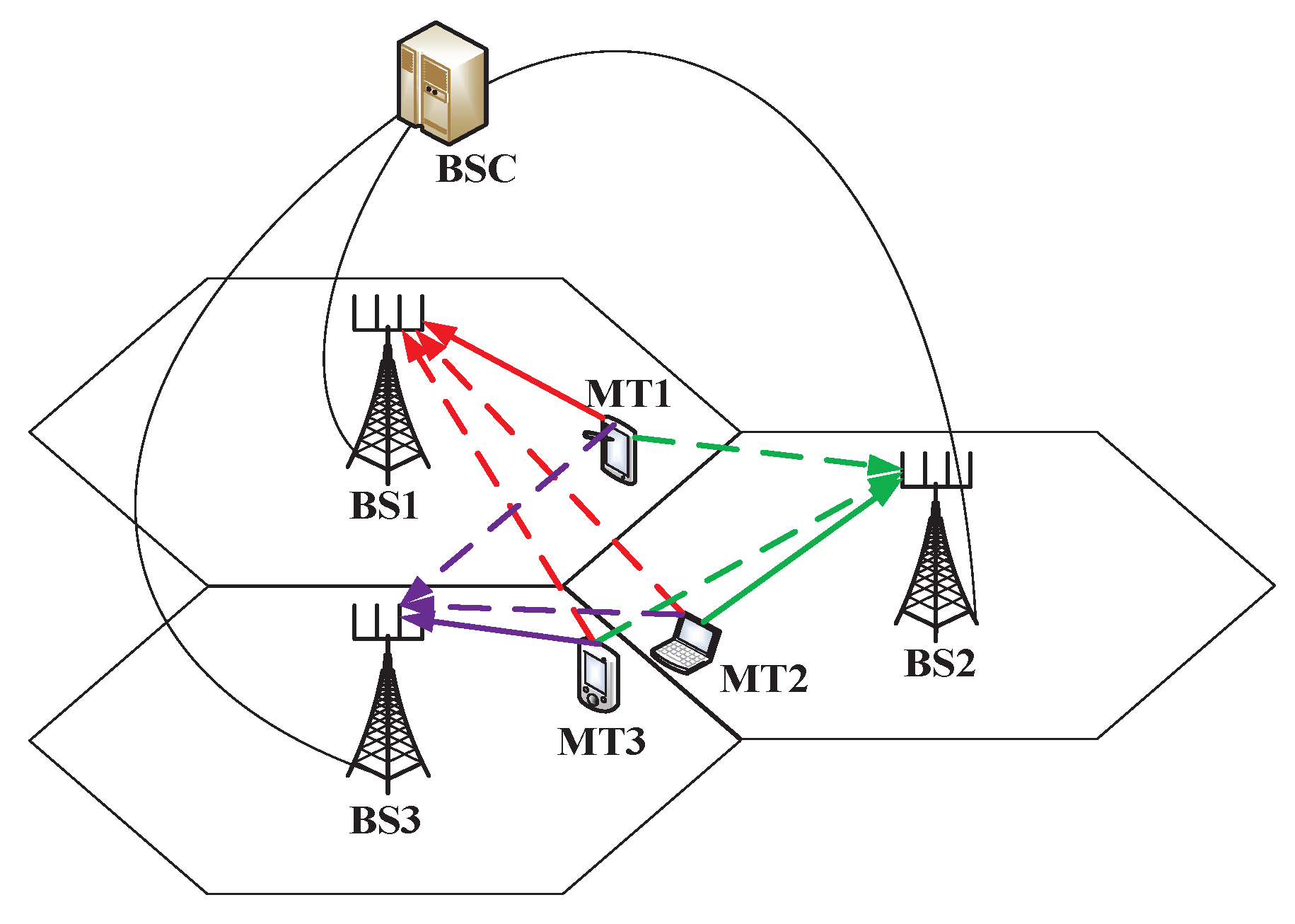
Figure 2 shows a diagram for an IA cooperative communication group in an uplink multi-cell communication example. In
Figure 2, the three hexagons represent thee three cells implementing IA cooperative communication, and they are an IA cooperative communication group. The different access MTs in the adjacent area of the cell refer to the users distributed on the edge of the cell. The BS is located in the center of each cell. The MT in one cell will cause interference to the other two cell users when it is communicating with the BS in this cell, and three BSs connect with the base station controllers (BSCs) through backhaul links. Taking the uplink as an example, each MT will cause interference to the BSs in the other two cells when they are sending data to the respective BS in their own cell.
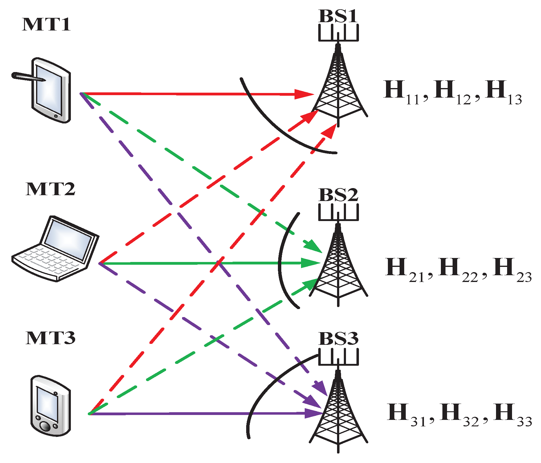
Figure 3 indicates the
K-user MIMO IC deriving from the uplink multi-cell cellular communication system. In
Figure 3, the multi-cell cellular communication system is converted into an interference channel consisting of three transmitters and three receivers. Each MT is equipped with
M antennas, and each BS is equipped with
N antennas. The solid lines represent the desired channel links including
, and dotted lines represent the interference channel links such as interference channel links
caused by MT1, interference channel links
caused by MT2, and interference channel links
caused by MT3.
In the IA cooperative communication group, different cells transmit data in the same frequency. Therefore, each MT and BS pair utilizes the time division multiplexing scheme to send pilots and train channels, ensuring that the BSs can accurately obtain the respective local CSI. The BSs estimate the local CSI for all the
K links connected to them through the pilot signal from the MTs. For the three-user IC in
Figure 3, each BSs need to occupy three time slots to obtain the local CSI. Taking BS1 as an example, it occupies three time slots to estimate its local CSI
. After obtaining the local CSI, each the BS will send these CSIs to the BSC through the backhaul link.
Then, the BSC will own the global CSI for this three-user interference channel, and it will employ these CSIs to calculate the TPC matrix, achieving interference alignment in the IA cooperative communication group. There are two calculation methods for the TPC matrix in our algorithm: (1) When the uplink and downlink have channel reciprocity in our cellular communication system (such as the TDD system), the BSC can employ the iterative interference alignment algorithm or the Max-SINR algorithm mentioned in [
14] to calculate the TPC matrix. (2) When the uplink and downlink do not have channel reciprocity in our cellular communication system (such as the FDD system), the BSC needs to employ the WMMSE mentioned in [
44] to calculate the TPC matrix. All TPC matrices calculated by the BSC will be sent back to each BS through backhaul links in the IA cooperative communication group and complete the acquisition process of the TPC matrices.
In addition to calculating the TPC matrices, our cellular communication system needs to quantify the TPC matrices into the TPC CB. In this process, there are two things to consider: the number of bits and the selection method for the TPC CB. According to (
13), the minimum feedback bits to achieve spatial multiplexing gain should be
. Then, we can determine that the number of CB bits used for quantifying TPC matrices is
. At present, there is no relevant conclusion to verify which quantization CB is better. In this experiment, we chose the random matrix quantization method to generate the quantization CB for the TPC matrices. In addition, we assumed that the quantization CB is known both by the BSs and MTs before the feedback.
On the BSs, systems will choose optimal quantization code words from the quantization CB. In this experiment, we utilized the Monte Carlomethod to achieve the selection of the quantization code words because of its low complexity. Comparing theoretical TPC matrices with every code word in the quantization CB, the BS will calculate the Euclidean geometric distance between theoretical TPC matrices and the quantization code word one by one according to the minimum distance principle for two subspaces:
where
is the TPC matrices for MT
i,
is the random quantization code word, and
is the number of feedback bits. The code word with the smallest Euclidean geometric distance is selected as the optimal quantization code word. Then, the selected code word is sent back to the corresponding MT through the feedback link, and the system will save the index of this code word.
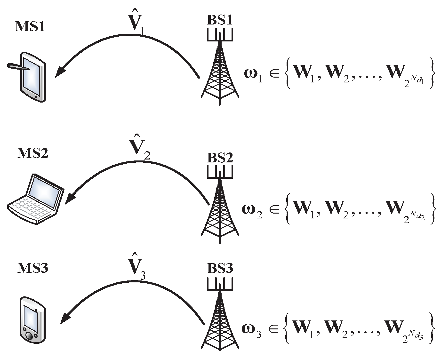
Figure 4 is the feedback diagram for the code word index of the TPC matrices. In the feedback duration for the quantization code word, the BSs will transmit the index of the quantization code word to the MT in their cell through control signaling. For example, BSi will determine the index of the optimal quantization code word from the quantization CB and transmit the index to MTi. Finally, MTi chooses the quantization code word from the index information of the TPC matrices and uses the code word as the TPC matrices to achieve spatial multiplexing gain in the interference alignment transmitting scheme.
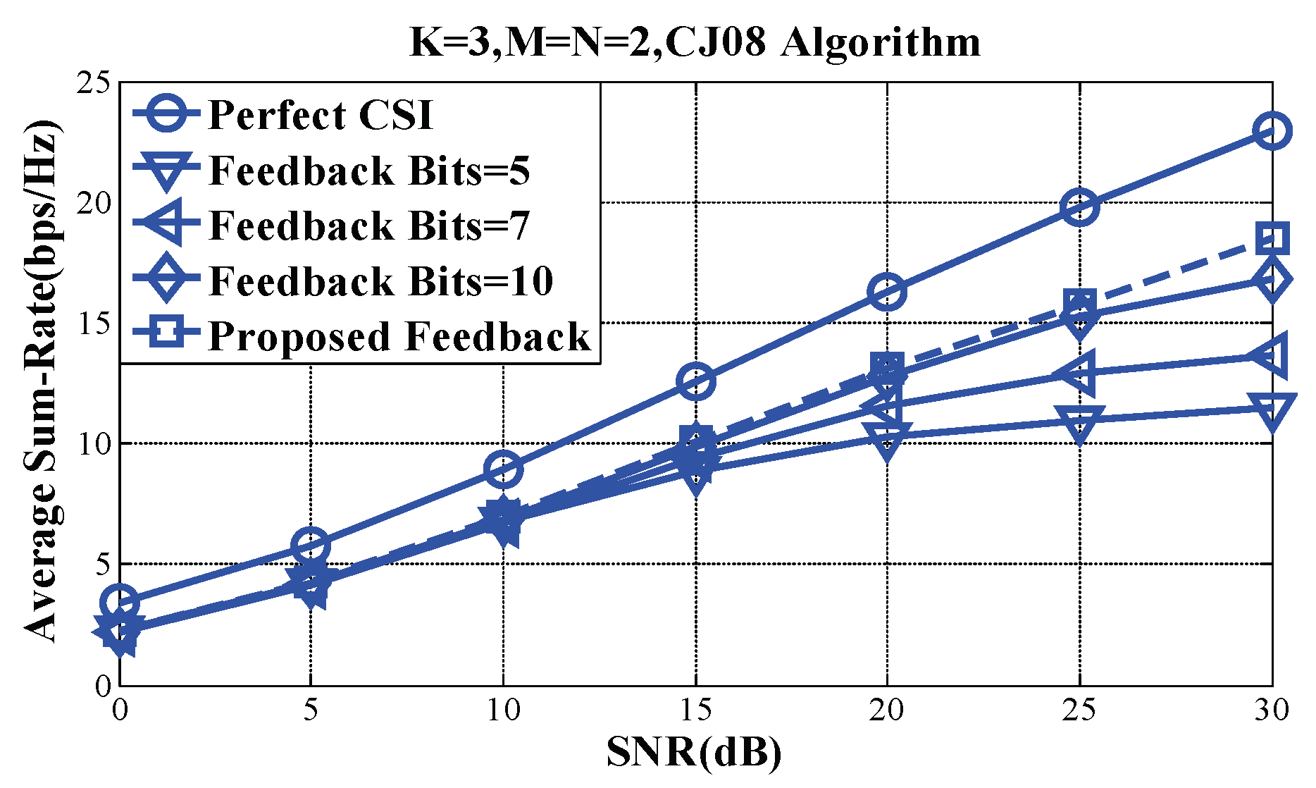
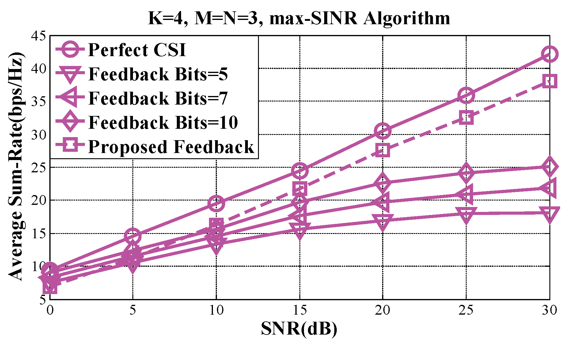
In
Figure 5, we compare the average sum rate of Algorithm 1 (the CJ08 algorithm) mentioned in [
14] for
users and for
antennas relying on perfect CSI, as well as on
feedback bits and on the specific number of feedback bits given by (
13) (labeled as Proposed Feedback in
Figure 2). The average sum rate of Algorithm 2 (the max-SINR algorithm) mentioned in [
14] is portrayed in
Figure 2, where we have
and
. For the average sum-rate performance investigations, we set the noise power to
, while
is defined as
. Due to the stochastic nature of the quantization CB, an average was taken over 100 different random CBs for a given channel realization. The numerical results of
Figure 1 and
Figure 6 show that the slope of the performance curve associated with the specific number of feedback bits given by (
13) was similar to that of the perfect CSI case. This means that the proposed TPC matrix feedback strategy was capable of achieving the same spatial multiplexing gain as the IA relying on the perfect CSI, although some inconsistencies still existed for some of the
due to the propagation of errors in the above pair of IA algorithms. The simulation results demonstrated the feasibility of the proposed feedback strategy, provided that the feedback bit rate is controlled sufficiently and promptly by the
according to (
13).


