Article

Virtual Sensor Using a Super Twisting Algorithm Based Uniform Robust Exact Differentiator for Electric Vehicles

1
School of Electrical and Electronics Engineering, Universiti Sains Malaysia, Nibong Tebal, Seberang Perai 14300, Penang, Malaysia
2
Center for Automotive Research (CAR), The Ohio State University, Columbus, OH 43212, USA
3
Department of Electrical and Computer Engineering, Comsats University Islamabad, Islamabad 44000, Pakistan
4
Electrical Engineering Department, Capital University of Science and Technology, Islamabad 44000, Pakistan
*
Author to whom correspondence should be addressed.
These authors contributed equally to this work.
Energies 2022, 15(5), 1773; https://doi.org/10.3390/en15051773
Submission received: 27 January 2022 / Revised: 17 February 2022 / Accepted: 20 February 2022 / Published: 28 February 2022

Abstract

:
The highly efficient Interior Permanent Magnet Synchronous Motor (IPMSM) is ubiquitous choice in Electric Vehicles (EVs) for today’s automotive industry. IPMSM control requires accurate knowledge of an immeasurable critical Permanent Magnet (PM) flux linkage parameter. The PM flux linkage is highly influenced by operating temperature which results in torque derating and hence power loss, unable to meet road loads and reduced life span of electrified powertrain in EVs. In this paper, novel virtual sensing scheme for estimating PM flux linkage through measured stator currents is designed for an IPMSM centric electrified powertrain. The proposed design is based on a Uniform Robust Exact Differentiator (URED) centric Super Twisting Algorithm (STA), which ensures robustness and finite-time convergence of the time derivative of the quadrature axis stator current of IPMSM. Moreover, URED is able to eliminate chattering without sacrificing robustness and precision. The proposed design detects variation in PM flux linkage due to change in operating temperature and hence is also able to establish characteristics of fault detection. The effectiveness and accuracy in different operating environments of the proposed scheme for nonlinear mathematical IPMSM model with complex EV dynamics are verified thorough extensive simulation experiments using MATLAB/Simulink.

1. Introduction

The rising awareness of climate change activities including global warming, transition to clean energy with vision of zero-emission vehicles and rapid decline of fossil fuels collates for electrifying the automotive industry—due to which many automotive industry players (OEMs, investors, suppliers, startups, and so on) are making sizeable investment decisions for survival and profitability.
In order to cope up with the challenges in EVs including but not limited to sustainability, high performance, high efficiency, and affordability in EV, ranging from Battery Electric Vehicle (BEV), Fuel Cell Electric Vehicle (FCEV), Plugin Hybrid Electric Vehicle (PHEV), and Hybrid Electric Vehicle (HEV), the car industry is going under radical transformation in electrified powertrain [1].

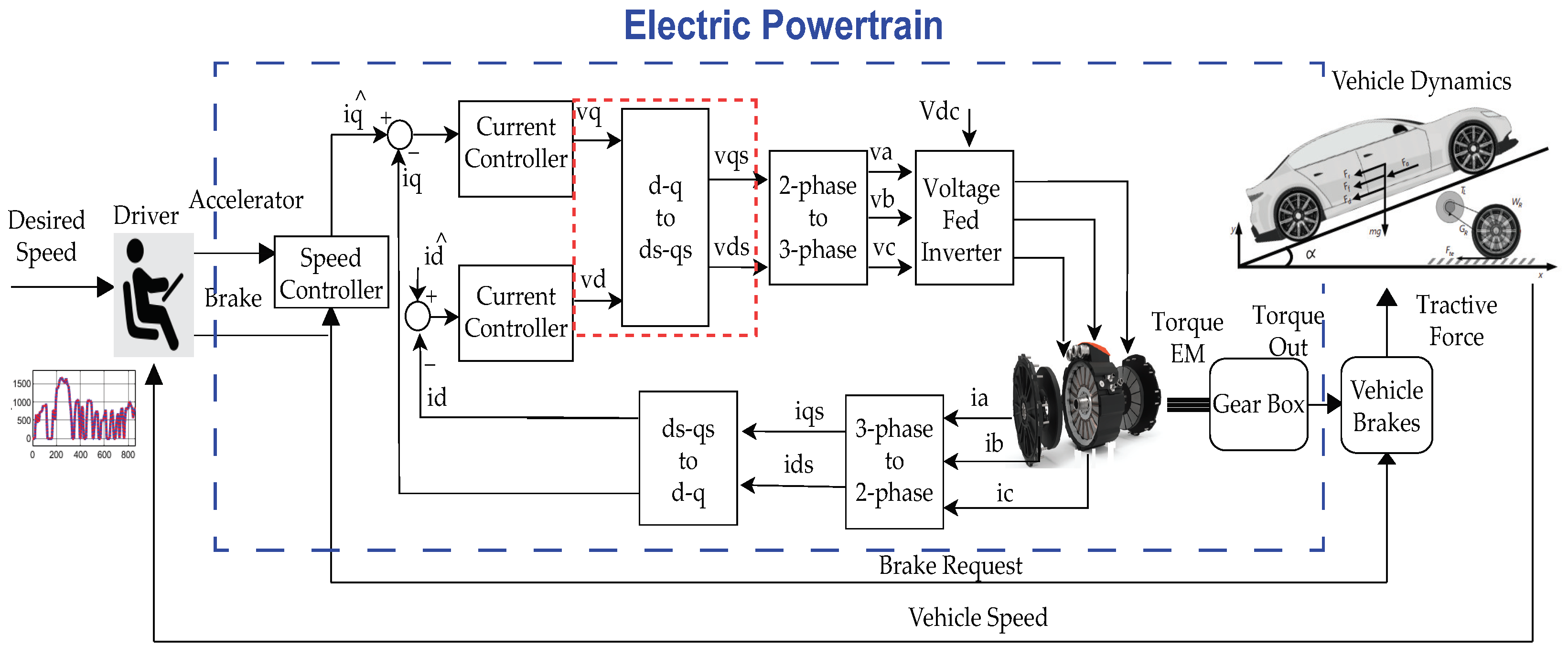
1.1. Electrified Powertrain

The electrified powertrain is the most substantial part of EV, which consists of traction motor, inverter and gearbox. Electric traction motor is a key component of the electrified powertrain. Permanent Magnet Synchronous Motor (PMSM) is the most suitable choice for traction motor among Induction Machine (IM), DC machines and Switched Reluctance Machine (SRM) due to its characteristics of wide speed operation range, high torque: at starting, at low speed with small volume design, good flux regulation capability, wide constant power operation, appropriateness for regenerative braking, fault tolerance and robustness in different environments [2,3]. PMSM is most commonly employed in the automotive industry; NIO ES6, NIO EC6, Tesla Model 3, Hyundai Kona, Volkswagen e-up, Hyundai Ioniq, Nissan Leaf, Toyota Prius and Chevrolet Volt [4].
PMSM has two types: IPMSM and SPMSM (Surface Permanent Magnet Mounted Synchronous Motor). IPMSM has easy mechanical control, higher armature reaction flux, air gap flux density greater than of remanence and large flux weakening capability as compared to SPMSM. Most importantly, IPMSM has higher permanent magnet flux linkage, and, hence, a smaller size, reduced weight (cost effective) and high torque production in wide speed range (high performance) make it the most preferred choice for traction applications.
The ideal torque, power and speed benchmark curves for electric traction motors are critical in automotive applications, as illustrated in Figure 1. The region I depicts the maximum constant torque of a traction motor as a result of acceleration and hill climbing requirements. The peak torque can be gained with the maximum current provided by an inverter till maximum power condition of the motor is achieved. It is worth mentioning here that the traction motor will be able to provide rated torque in this region only. In region II, torque reduces with the increase of speed and power remaining constant.
EV electrified powertrain control performance degrades because of parameter variation. The IPMSM based electrified powertrain parameters are affected due to a change in operating conditions caused by drive cycles (highway and urban traffic conditions), vehicle load and temperature influence [5]. As a result, this affects stator resistance, winding of machine [6], d-axis and q-axis inductances, and permanent magnet flux linkage (both intrinsic coercivity H c i and remanance B r [7]). PM flux linkage is one of the most substantial parameters vulnerable to high temperature. Its importance is evident from the fact that PM with high flux linkage is used to increase power density, which results in several key requirements mentioned above of torque over a wide speed range, minimized energy consumption and reduction of weight, resulting in cost effectiveness and derating of torque [8]. Due to the PM flux linkage influenced and hence derating torque, the electrified powertrain of EV may suffer the following [9]:
  • Being unable to meet the road loads in all operating conditions;
  • Aging (Reduced life span);
  • Inefficient powertrain operations or high power loss.

1.2. Related Work

To overcome these challenges due to temperature, PM flux linkage parameter variation needs to be obtained, which cannot be directly measured. Even the infrared thermography (limited to surface magnet) is not a viable solution for measuring PM flux linkage of IPMSM due to the high cost and construction drawbacks depending on magnets and winding temperature [10]. In addition, the extra sensors do not work during motor operation for thermal modelling [11]. The invasive methods can also be used but have their own limitation of working only at no load conditions with increasing current and harmonics [12]. Thus, taking into consideration the aforementioned bottle necks, online parameter estimation, which can perform in various operating ranges, is the most suitable choice for PM flux linkage estimation of IPMSM [13].
Several online methods have been previously implemented to solve the parameter estimation problems [14]—affine projection algorithm [15], extended Kalman filtering (EKF), Kalman like adaptive observers [16] and model reference adaptive system [17], which suffer from high computational load and complex designs. The Model Predictive Current Control (MPCC) for PMSM drives has also been proposed in the past [18] but mostly face torque and current ripples. The artificial Intelligence (AI)-based neural network [19] and genetic algorithm [20] show good performance but are considered expensive solutions because they require a large data set, increasing the training time and computational cost.
Ref. [21] proposes an improved deadbeat predictive stator flux control (DPSFC) based on a disturbance observer to address the problems of steady state tracking error and robustness decrease due to the detrimental parameter mismatch and disturbance. The Linear Disturbance Observer has also been used in [22] for PMSM parameter estimation. It is not a considered a preferred choice as it relies on precise models. Luenberger and extended Luenberger methods are also implemented for PMSM drives [23], but their stability depends on the actual rotor speed value.
Sliding Mode Observer (SMO) has also been used for decades due to its intrinsic parametric robustness, low computational burden, modeling uncertainties and easy implementation properties [24,25]. A robust deadbeat predictive controller with delay compensation based on composite sliding mode observer for PMSMs has been proposed [26], which simultaneously estimates the future current value and lumped disturbance caused by the parameter mismatch of inductance, resistance and flux linkage. However, a sliding mode faces a crucial challenge of a chattering phenomenon. To overcome this obstacle, researchers have proposed sliding surface design modification (integer order integral, fractional order and terminal sliding mode) [27,28,29]. These modifications face numerous challenges: parameter tuning of gains in order to ensure a balance between chattering and a disturbance rejection property, determination of the frequency band for fractional order operator and poor convergence, especially when the system state is far from equilibrium. Sliding mode integration with artificial intelligence is also very old and has several advantages and disadvantages, but the most critical disadvantage is the computational load it takes, which makes it difficult to implement [30,31].
High Order Sliding Mode (HOSM) is another preferred choice for parameter estimation of IPMSM, in which the control input acts on higher derivatives of sliding surface. HOSM was introduced by [32], which provides better performance in terms of chattering effects suppression while enacting the advantages of conventional sliding mode control. To cater aforementioned effects, differentiators in HOSM twisting, suboptimal, prescribed convergence law, quasi-continuous algorithm and Super Twisting Algorithm (STA) have been proposed and applied in the past [33,34].

1.3. Major Contributions

Inspired by the above discussions to accomplish accurate torque production and desired speed for meeting road loads, reducing aging and increasing efficiency of EVs, advance control requires accurate knowledge of IPMSM parameters widely used in the powertrain of EVs. The authors have proposed a novel STA based URED of higher order sliding-mode for development of virtual sensors to monitor the immeasurable and most important PM flux linkage parameter of the electrified powertrain. For estimation strategy, first the STA-based URED is constructed for estimation of the time-derivative of q-axis current in finite time, independent of the initial conditions [35], followed by the PM flux linkage estimation scheme. Moreover, the architecture is able to detect a decrease in permanent flux linkage due to variation in operating temperature. To verify the effectiveness of the proposed scheme, a simulator for the complete electrified powertrain is designed using 3 KW IPMSM, simulated against the Worldwide harmonized Light vehicles Test Procedures (WLTP) class 3 driving cycles commonly adopted by the automotive community [36,37], and voltages are obtained. The stator voltages in d-q coordinates are then used for the testing of an open loop novel STA based URED scheme. Extensive simulation experiments are carried out in Matlab/Simulink, which demonstrates exact convergence and robust estimation. It has also been realised that the proposed virtual sensor has the potential for online implementation after minor tuning.
The rest of this paper is arranged as follows: Section 2 illustrates mathematical modeling of IPMSM; Section 3 depicts a novel strategy of STA-based URED; Section 4 discusses simulation experiment results; and the conclusions are presented in Section 5, followed by references.

2. EV-Based IPMSM Dynamics

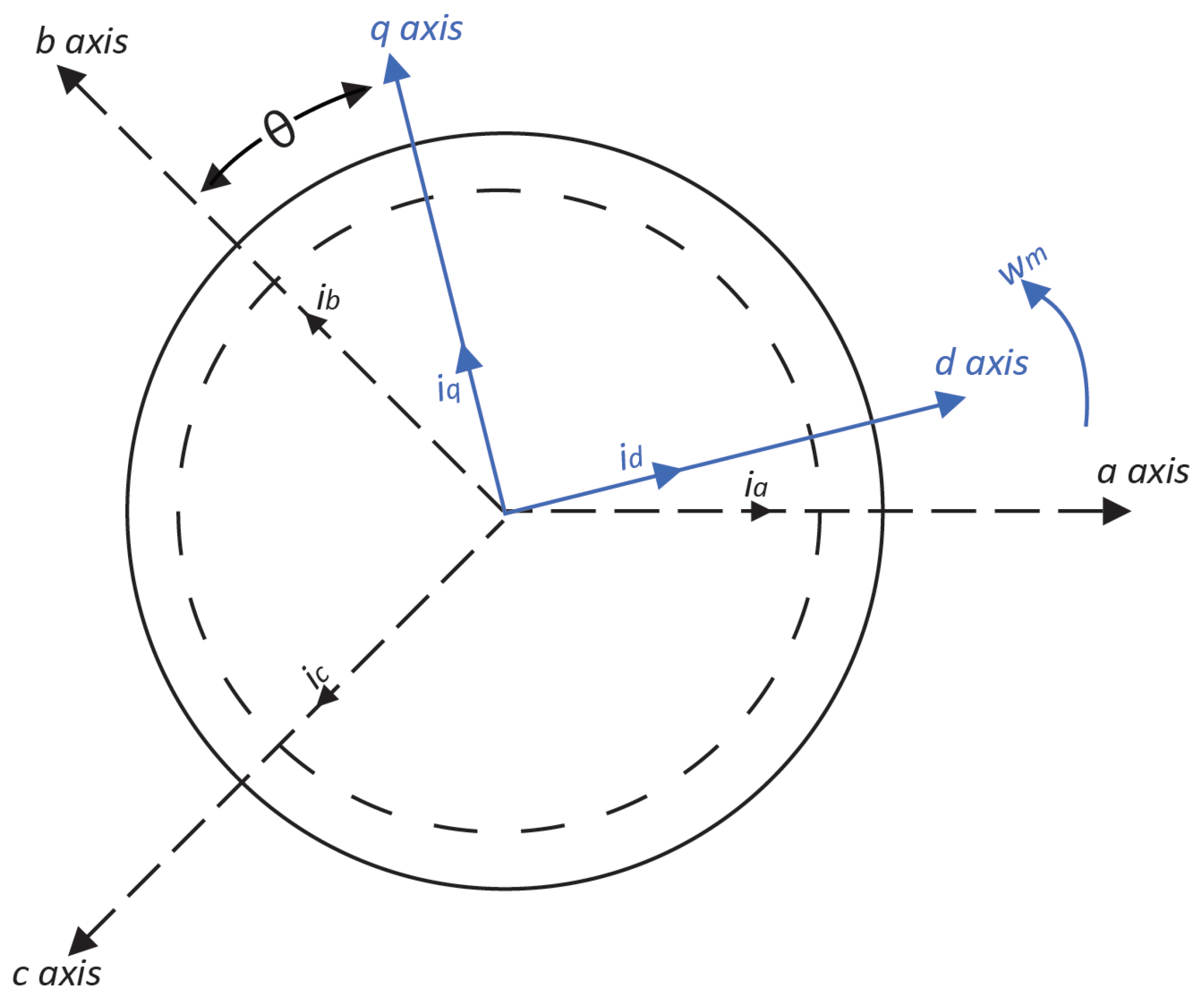
2.1. IPMSM Mathematical Modelling

In order to analyze the characteristics of the three phase nonlinear IPMSM for different operating temperatures, the most exclusive IPMSM model among [38,39,40,41,42,43,44,45] has been adopted. Saturation, coupling, spatial harmonics and core losses are assumed negligible in this nonlinear mathematical model.
The IPMSM has no rotor circuits, and the three phase voltage v a b c s and current i a b c s equations for the stator windings are taken into consideration as follows:
v a b c s = R s i a b c s + d ψ a b c s d t
The flux linkage ψ a b c s of IPMSM has two components due to stator currents and two because of flux linkage of permanent magnets given by:
ψ k a s = ψ k s a s + ψ k s b s + ψ k s c s + ψ k s f
where: ψ a s f , ψ b s f , ψ c s f are flux linkages due to stator currents, and ψ k s f is flux due to permanent magnets and k = a , b , c . These flux linkages are also be expressed in terms of field current I f and related inductances L k s a s , L k s b s , L k s c s as follows:
ψ k a s = L k s a s i k s + L k s b s i k s + L k s c s i k s + L k s f I f
where k = a , b , c . The total flux linkage of an IPMSM in the form stator inductance L s and L f mutual inductances are given by:
ψ a b c s = L s i a b c s + L f I f
where:
L s = A L J L J = 1 , 2 , 3 .
A L J = 1 2 L A L B c o s 2 ( θ r + ( 1 L + J ) π 3 ) , L J L l s + L A L B c o s 2 ( θ r 2 ( L 1 ) π 3 ) L = J 1 2 L A L B c o s 2 ( θ r ) , 1 < L < J & J = J m a x o r v i c e v e r s a
i a b c s = i a s i b s i c s
L f = L s f I f c o s θ r c o s ( θ r 2 π 3 ) c o s ( θ r 4 π 3 )
L s f depends on the amplitude of the permanent magnet flux linkage, c o s ( θ r ) rotor position. L l s is the leakage inductance, L A represents average value of magnetizing inductance, and L B represents variation in value of magnetizing inductance.
The direct quadrature coordinates-based equivalent circuit is used for modelling of IPMSM. A cross sectional representation of 3-phase, 2 pole IPMSM along with two references frames are depicted in Figure 2. The d-q reference frame consists of stationary reference frame in which a d-q coordinate system does not rotate, which is known as Clark transformation, and the rotating reference frame in a d-q coordinate system rotates at a speed of rotor w or a rotating magnetic field. This type of transformation is known as Park transformation. The angle between rotating and stationary reference frame may vary over time.
The three phase abc variables f a , f b , f c , which are voltages and currents of IPMSM, k chosen arbitrarily can be transformed into a d-q axis stationary reference frame f d s , f q s using the equations given below:
f d s = k [ f a c o s ( θ ) + f b c o s ( 2 π 3 ) + f c c o s ( 2 π 3 ) ]
f q s = k [ f a s i n ( θ ) + f b s i n ( 2 π 3 ) + f c s i n ( 2 π 3 ) ]
Similarly, the transformation of abc variables can be transformed into a d-q variable in stationary reference using coefficient k = 2 3 , which reflects that the magnitude of d-q is exactly equal to abc variables. This transformation is also called magnitude invariance transformation and is given by:
f d = 2 f a f b f c 3
f q = 1 3 ( f b f c )
For the modeling and analysis of IPMSM, the transformation from a stationary reference frame into a rotating reference frame f d e , f q e is required, which can be formulated using Equations (11) and (12) as follows:
f d e = f d s c o s θ + f q s s i n θ
f q e = f d s s i n θ + f q s c o s θ
From the circuit equivalent dynamics, the IPMSM voltage equations can be written in an arbitrary reference rotating frame at speed w as:
V d s = R s i d s + d d t ψ d s p ω m ψ q s
V q s = R s i q s + d d t ψ q s + p ω m ψ d s
The transformation into a d-q axis rotating at arbitrary speed w of stator flux linkage of IPMSM mentioned in Equation (4) can be formulated as follows:
ψ d q e = B L J i d q + c o s ( θ θ r ) ) s i n ( θ θ r ) ) 0 ψ P M L J = 1 , 2 ,
where
B L J = L l s + 3 2 ( L A L B c o s 2 ( θ θ r ) ) , L = J 3 2 s i n 2 ( θ θ r ) L J
The stator flux linkage with a constant inductance in the rotor frame can be resolved into:
ψ d s = L d s i d s + ψ P M
ψ q s = L q s i q s
The output torque is obtained by dividing the output power by the rotor speed w m :
T e = 3 P 2 ( L d s L q s ) i d s i q s R e l u c t a n c e t o r q u e + ψ P M i q s M a g n e t i c t o r q u e
The IPMSM model can be rewritten in explicit form by opting the state variables ( θ m , ω m , i d s , i q s ) as follows:
θ ˙ m = ω m
ω ˙ m = 3 p 2 J [ i q s ψ P M + ( L d s L q s ) i d s i q s ] B J ω m 1 J τ L
i d s ˙ = 1 L d s ( R s i d s + p L q S ω m i q s + V d s )
i q s ˙ = 1 L q s ( R s i q s + p L d S ω m i d s p ψ P M ω m + V q s )
Temperature changes have a direct impact on PM flux linkage, thus torque production as stated in Equation (27). As the temperature rises, permanent magnet flux decreases due to which torque derates and hence the performance of electrified powertrain deteriorates [6,7]. The change of torque with respect to speed with variation in operating temperature is shown in Figure 3. The IPMSM model derived in Section 2.1 and parameters mentioned in Table 1 have been used to investigate the temperature influenced IPMSM-based electrified powertrain. Due to elevated temperature, the starting torque, which results in a decreased amount of air gap that actually converts into a mechanical form. This phenomenon ultimately ends up with a lower efficiency of IPMSM:
ψ P M = ( B r T ) d A
ψ P M = ψ P M 0 [ 1 + α T T 0 100 ]
It should be noted that α is a negative temperature coefficient, which indicates decreasing remanence with an increase in temperature. An example of temperature coefficient for the mostly used permanent magnet Neodymium iron boron (NdFeB) magnet from Arnold technologies is α = −12%/°C. NdFeB is one the best magnetic materials present, due to its coercivity H c i and residual flux density B. Coercivity indicates the intensity of the magnetic field to reduce magnetization and residual flux intensity, also known as remanence, represents the remaining magnetic field. If the permanent magnets are exposed to temperatures above the operating temperature, its original flux level cannot be restored when it returns to an original temperature, irreversible changes occur and there is a big loss for magnetism.

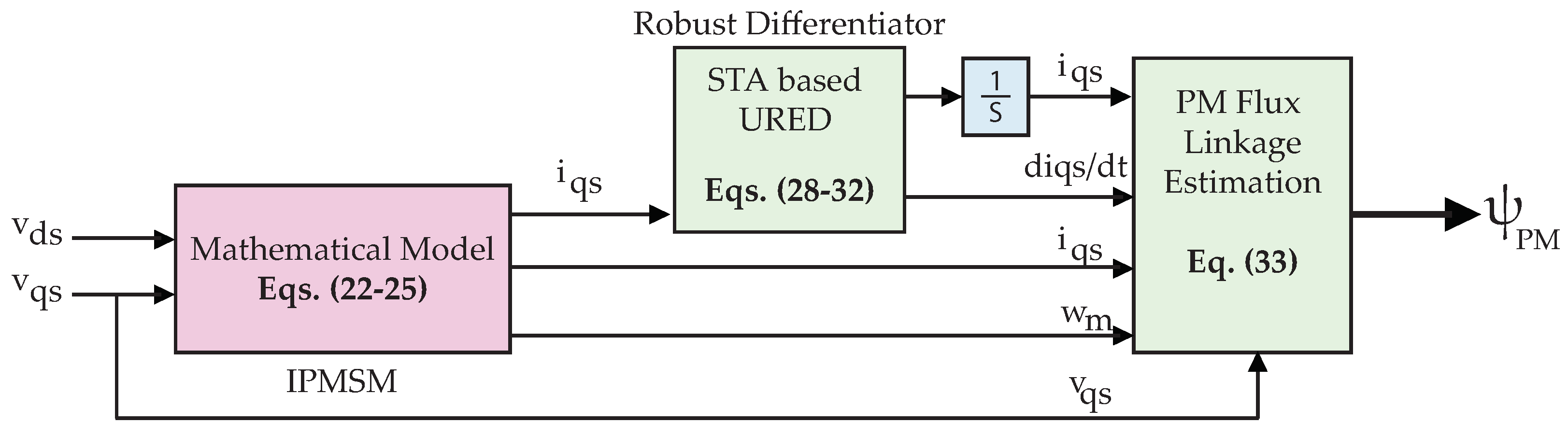
3. Virtual Sensor Development Strategy

In EVs, widely used IPMSM requires accurate knowledge of parameters for accurate torque production and maximal efficiency. Its performance is degraded due to the parameter variation against temperature change.
ψ P M , being the most critical motor influenced parameter by temperature, is considered and estimated using STA based URED. The idea of virtual sensor is presented in Figure 4. The V d s , V q s , i d s , i q s , ω m are measured values available and the derivative of i q needs to be computed for estimation of the PM flux linkage. The IPMSM mathematical model derived in Equations (22)–(25) is simulated and measured i q s is fed into STA based URED. URED is constructed using high order nonlinear STA terms to have the uniform and exact convergence in the differentiator.
The value of differentiator with measured V q s , i d s , i q s , ω m values are fed as input to the PM flux linkage estimation block to compute PM flux linkage by using Equation (33).
The estimation of the flux linkage ψ P M is carried out in two steps. Initially, the time derivative of the measured q axis current i q s of the IPMSM is computed by employing URED; then, Equation (25) is algebraically solved to yield ψ P M .
Let i q s , be the input signal to be differentiated. Then, ς 0 = i q s and its time derivative ς 1 = i q ˙ represent states of the second order system given as:
ς ˙ 0 = ς 1 , ς ˙ 1 = i q ¨ .
In order to construct a URED which gives a robust estimation of i q s ˙ in finite time, independent of the initial conditions, the following methodology is adopted. Consider a sliding variable σ 0 = z 0 ς 0 , which represents the difference between estimated and actual signal to be differentiated, respectively. Now, by using the results in [35], the STA based URED scheme is characterized as follows:
z 0 ˙ = k o p t 1 ϕ 1 ( σ 0 ) + z 1 , z 1 ˙ = k o p t 2 ϕ 2 ( σ 0 ) ,
where z 0 and z 1 are the estimates of i q s and its time derivative i q s ˙ , respectively, and k o p t 1 , k o p t 2 + represent the gains of URED. The auxiliary functions ϕ 1 and ϕ 2 are given as follows:
ϕ 1 ( σ 0 ) = | σ 0 | 1 2 s i g n ( σ 0 ) + μ | σ 0 | 3 2 s i g n ( σ 0 ) , ϕ 2 ( σ 0 ) = 1 2 s i g n ( σ 0 ) + 2 μ σ 0 + 3 2 μ 2 | σ 0 | 2 s i g n ( σ 0 ) ,
where μ + is the design parameter of URED. The higher degree nonlinear STA terms in Equation (30) provide finite-time and exact convergence to i q . Moreover, the convergence is independent of the initial conditions of URED.
The exact convergence of URED can only be achieved if the gains k o p t 1 , k o p t 2 satisfy the following conditions in a set:
K = k o p t 1 , k o p t 2 R 2 | 0 < k o p t 1 2 L , k o p t 2 > k o p t 1 2 4 + 4 L 2 k o p t 1 2
k o p t 1 , k o p t 2 R 2 | 0 < k o p t 2 2 L , k o p t 2 > 2 L
The exact convergence can be shown through global Lyapunov function as:
V ( σ ) = ζ T P ζ σ = [ σ 0 σ 1 ]
where vector ζ T = [ ψ ( σ 0 ) σ 1 ] and P = P T is a symmetric positive definite matrix. σ is a vector of auxiliary functions.
After the establishment of sliding mode in the manifold σ 0 , z 0 = i q and z 1 account for i q s ˙ . Furthermore, by employing Equation (25), ψ P M is computed as:
ψ P M = 1 p ω m ( i q ˙ L q + R s i q p L d ω m i d V q )

4. Simulation Experiments

The method outlined in the previous section for the development of virtual sensor for immeasurable PM flux linkage has been validated on electrified powertrain simulated in MATLAB/Simulink under steady state conditions. Steady state conditions mean that voltage values of v d s and v q s are considered constant.

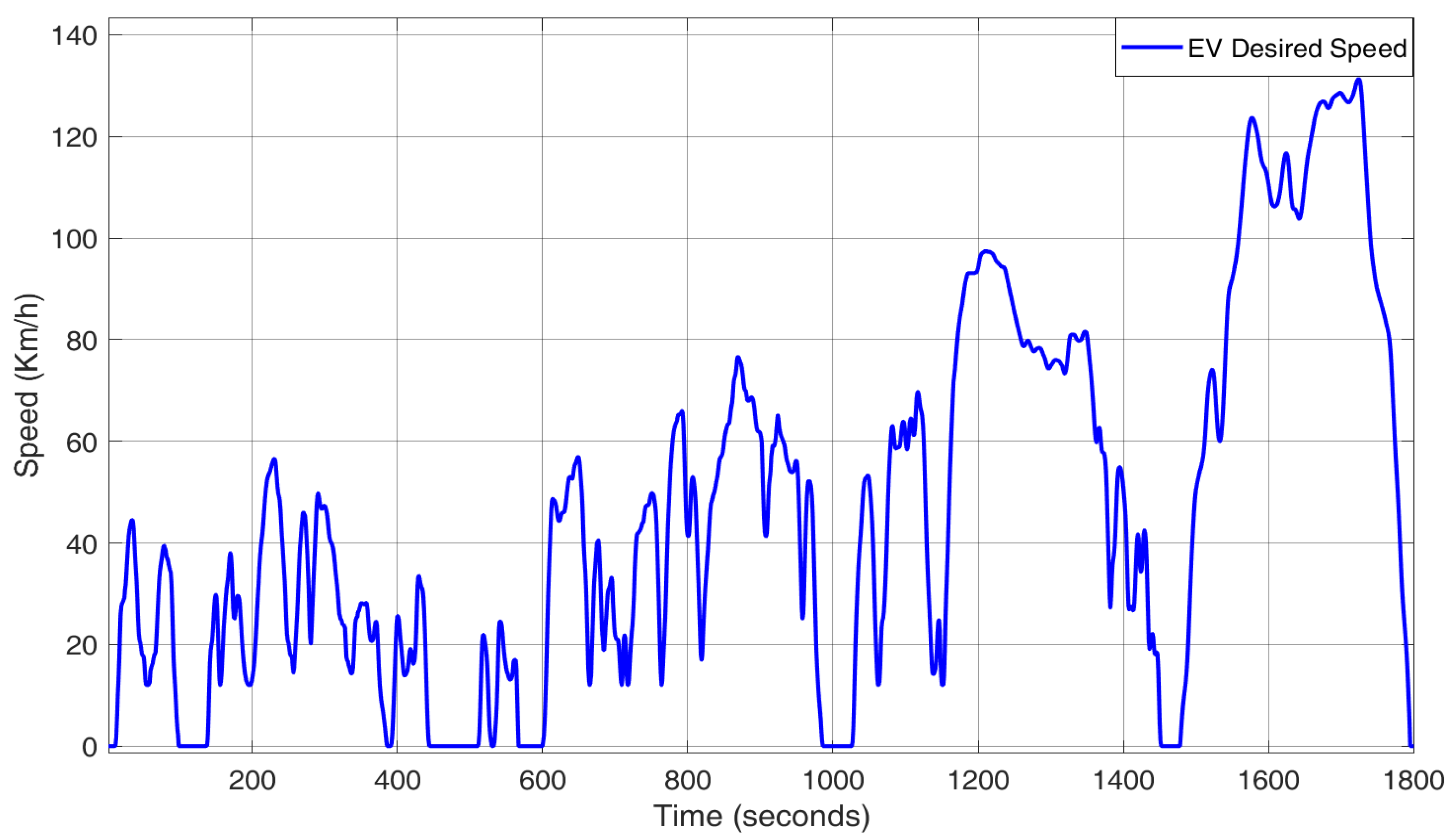
4.1. Simulator Design

To obtain the real-time values of the stator voltages, electrified powertrain was simulated using Field Oriented Control (FOC) for 3 kW IPMSM parameters depicted in Table 1. Block diagram of electrified powertrain with FOC is shown in Figure 5. An electrified powertrain consists of an inverter embedded with a controller, IPMSM and gearbox with torque inputs and outputs, and the rest of the vehicle dynamics. IPMSM in electrified powertrain is controlled to deliver the required torque against the road loads using an FOC control strategy. The WLTP class 3 driving cycle shown in Figure 6 was used as an input to an electrified powertrain. The driving cycle includes periods of constant acceleration, deacceleration, and various speeds in urban and highway driving areas. The FOC is used to generate the voltages fed into an inverter and then to the IPMSM. For practical consideration, the gain of voltage fed inverter is assumed to have unity, while keeping the load torque constant in controlled environmental conditions.
The demonstrated electrified powertrain is not solely applied to IPMSM but takes into account the EV aerodynamics and mechanics principles [46]. The speed dynamics of wheel drive and load torque in Equations (35) and (36) are described in the traction motor referential.
The highlighted part of stator voltages v d and v q in red are stored separately for the testing of virtual sensor in steady state conditions presented in Figure 7 and Figure 8:
ω ˙ m = p J ( τ e τ L B ω m )
τ L = ( F r + F f + F a + F d ) w r
Furthermore, IPMSM speed is proportional to vehicle speed (v), which can be expressed in terms of gear box ratio ( G r ) and wheel radius ( w r ) by:
ω m = G r w r v
All the simulation experiments were prepared using temperature influenced stator resistance as represented in Equation (37) at steady state conditions:
R s T = R s 0 ( 1 + γ 0 Δ ( T ) )
where γ 0 = 3.93 × 10 3 / C , R s T , R s 0 are winding resistances at operating and nominal temperature of 20 C and Δ ( T ) is the difference between operating and nominal temperatures.

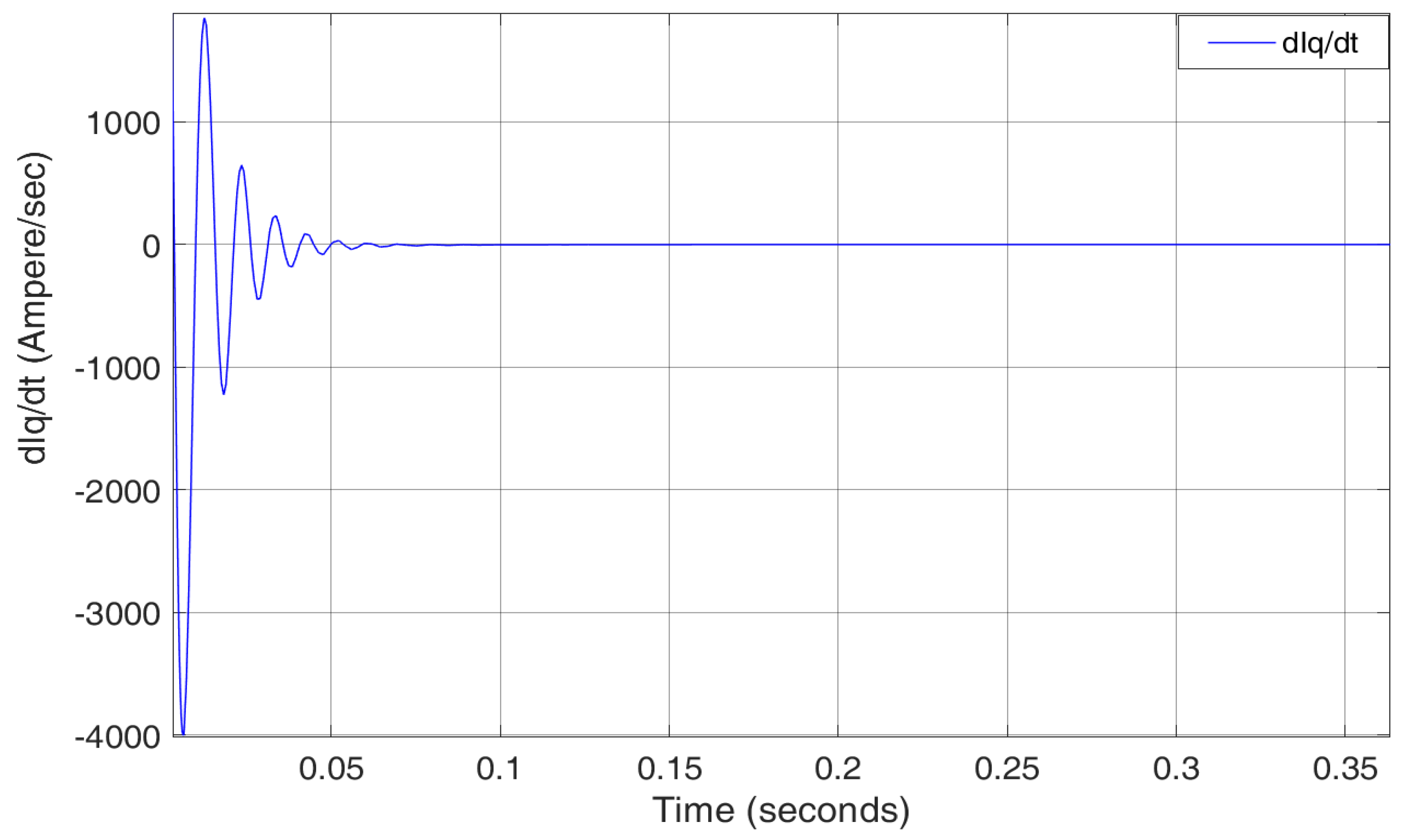
4.2. Estimating/Sensing of an Immeasurable Parameter
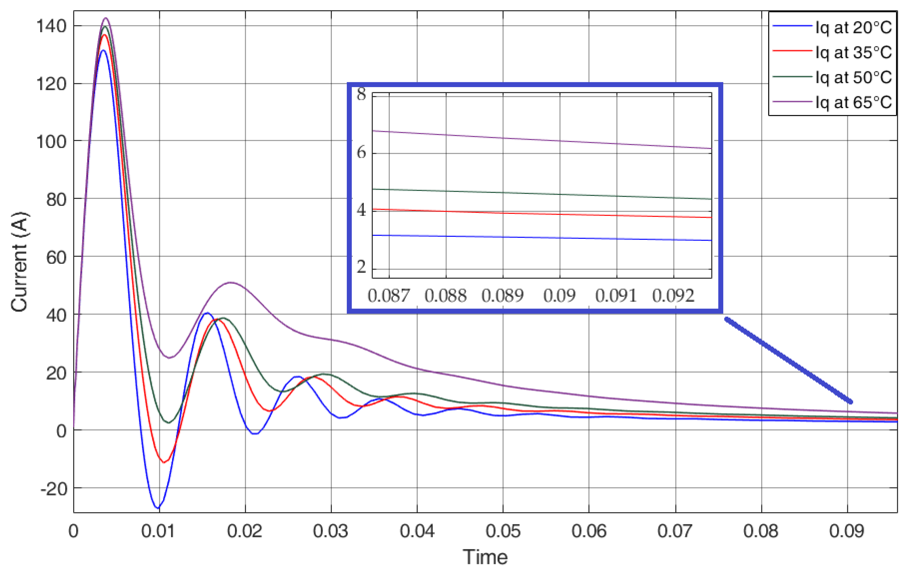
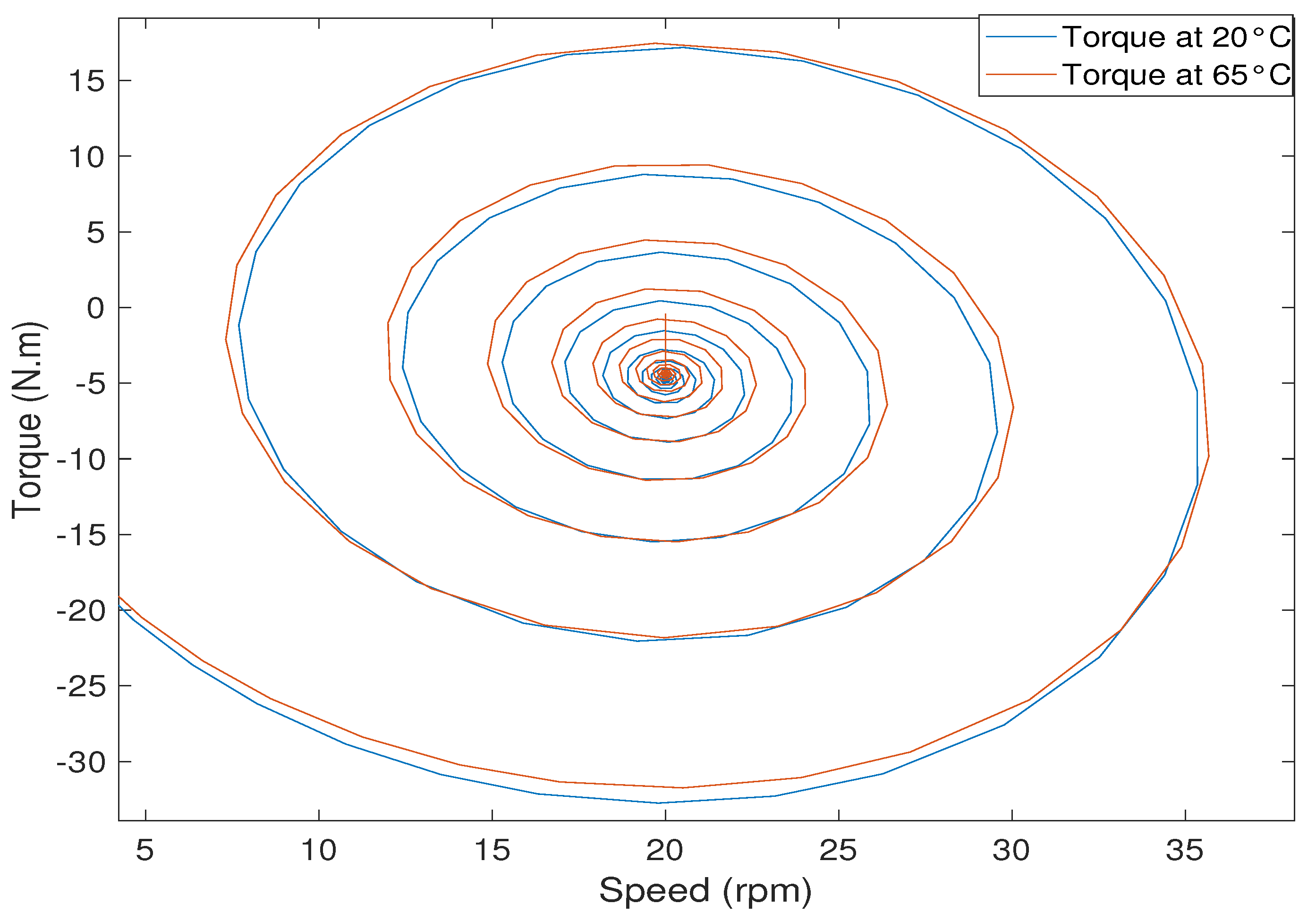
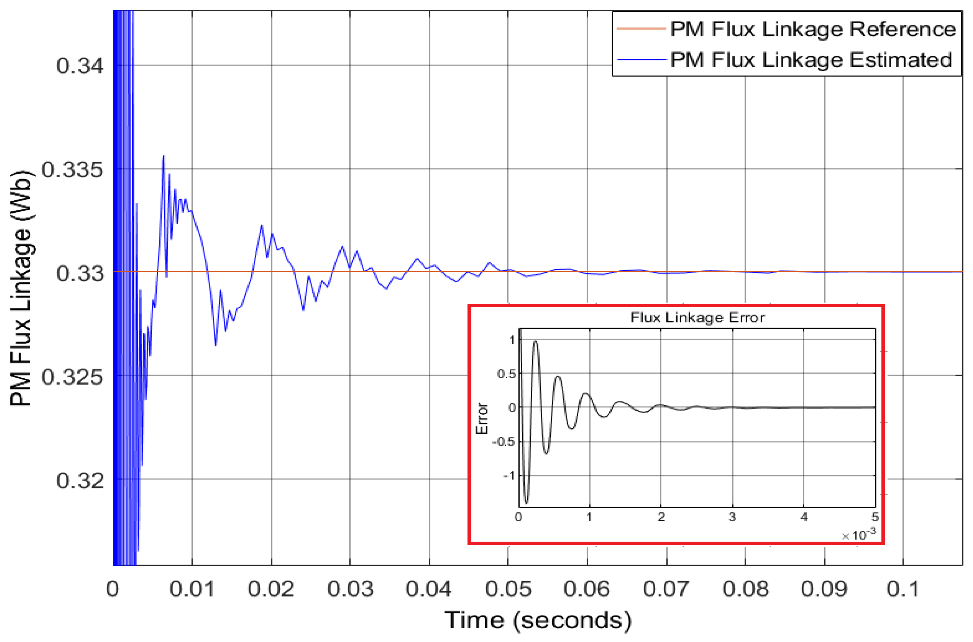
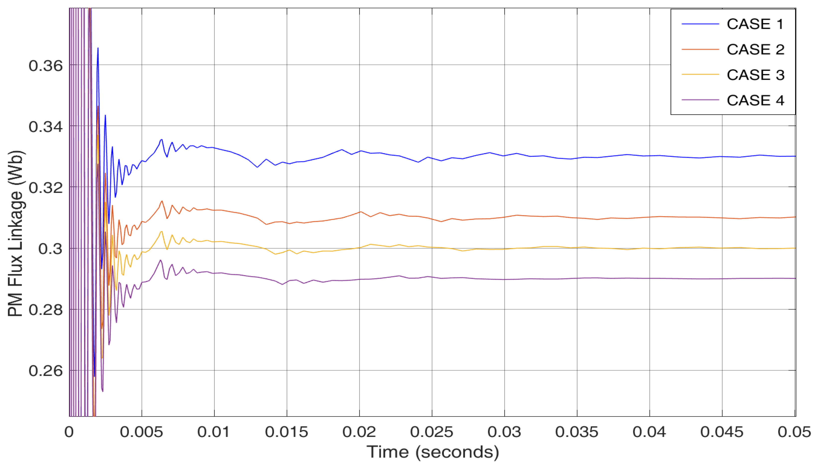
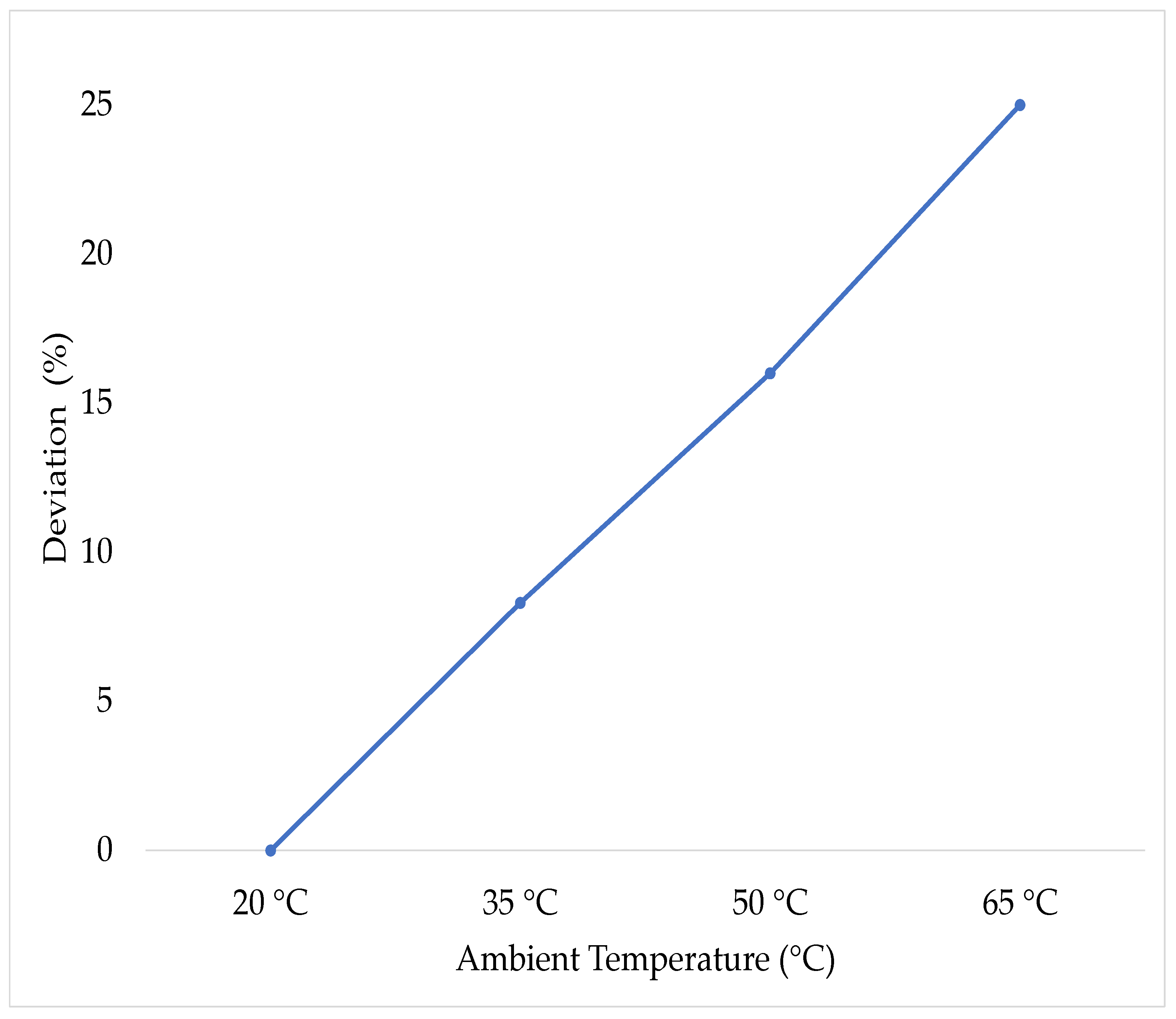
Estimation of immeasurable PM flux linkage provides useful information about efficacy of the electrified powertrain. Even the infrared thermography (limited to surface magnet) is not a viable solution for measuring PM flux linkage and extra sensors also do not work during motor operation for thermal modelling [11]. Thus, taking into consideration the aforementioned challenges, the proposed virtual sensor designed using STA based URED method for the ψ P M mentioned in Equation (33) successfully estimates the value at a nominal temperature of 20 C as shown in Figure 9. It can be observed that the settling time is less than 0.09 s, and the convergence remains close to zero. The parametric values tuned for the estimator are as follows: μ = 950 , k o p t 1 = 50 , k o p t 2 = 200 .
These parametric values are also able to estimate the PM flux linkages with change of temperatures from 20 C to 65 C by varying the stator resistance presented in Equation (37), shown in Figure 10. The following can be observed from the figure:
  • Case 1:
    The PM flux linkage is estimated to be 0.33 w b at a nominal temperature of 20 C. There is no change in stator resistance. The settling time remains less than 0.09 s and the convergence error remains close to zero.
  • Case 2:
    As the operating temperature of IPMSM-based electrified powertrain increases to 35 C, the stator resistance value increases around 5 % . Therefore, PM flux linkage decreases, and the decrease is estimated to 0.31 w b . The settling time remains less than 0.09 s, and the convergence error remains close to zero.
  • Case 3:
    With the increase of operating temperature of IPMSM-based electrified powertrain to 50 C, the stator resistance value increases around 11 % . The proposed virtual sensor is still able to detect decreased PM flux linkage. The estimated value from the figure can be seen to be 0.30 w b . The settling time still remains less than 0.09 s and the convergence error remains close to zero.
  • Case 4:
    The stator resistance value increases 17 % with the increase of operating temperature of IPMSM-based electrified powertrain to 65 C. The PM flux linkage decreases, and the decrease is still correctly detected and estimated to be 0.29 w b . The settling time remains less than 0.09 s, and the convergence error remains close to zero.
Figure 11 represents the i q , corresponding to the PM flux linkage with a change of temperature from 20 C to 65 C. The settling time can be noted to be 0.1 s. Moreover, it can also be seen that, with an increase of temperature, stator current i q also increases and PM flux linkage decreases. The stator current q-axis error at nominal temperature 20 C is also presented in Figure 12. The transient of error is between 0.24 to −0.16 approximately. The setting time 0.14 s can be observed.
The derivative of i q s mentioned in Equation (25) is presented in Figure 13. This estimated derivate current is of high importance, as it required as an input to estimation of permanent magnet flux linkage mentioned in Equation (33). The value of it changes until convergence of the stator current i q s . The value of derivative of current will be higher if the difference between the reference value of stator current i q s and the estimated value is greater. The efficient tracking of an STA based URED technique can be observed throughout the experimental results with the convergence error remaining close to or almost zero.
Figure 10 illustrates a decrease of PM flux linkage as a result of variation in operating environment from 20 C to 65 C under steady state conditions and hence an increase in mean square error. Figure 14 clearly shows the deviation of PM flux linkage with an increase in temperature. This decreases and, as a result, also validates the proposed scheme fault detection ability. Furthermore, the proposed estimation scheme is not only computationally cost effective but has a potential for pragmatic online implementation.
The mean square error computes a decrease PM flux linkage as a result of variation in an operating environment from 20 C to 65 C under steady state conditions. Using mean square error, PM flux linkage deviation with an increase in temperature is computed, as shown in Figure 14.
The experiments’ simulation results clearly show that, with an increase of temperature, the PM flux linkage decreases, which derates torque and hence is unable to meet the roadloads, loss of lifetime and high power loss. The increase in deviation also validates the proposed scheme fault detection ability. Furthermore, the proposed estimation scheme is not only computationally cost effective but has a potential for pragmatic online implementation.

5. Conclusions

A virtual sensor using an STA based URED for PM flux linkage online estimation has been designed by considering nonlinear IPMSM centric EV. The accuracy analysis in steady state has been demonstrated through rigorous simulation experiments, which established an efficient tracking of the proposed scheme. The results illustrated a convergence of the derivative of stator current, which guaranteed accurate estimation of PM flux linkage irrespective of the initial conditions. Moreover, the simulation experiments’ results validate the fault diagnosis ability of the proposed design. Furthermore, the designed scheme is computationally cheap and can be extended to practical implementation.
Hardware in the loop testing of virtual sensor along with a controller design to compensate the thermal derating torque will be used for IPMSM-based EVs.

Author Contributions

Conceptualization, H.M., M.K.I., A.H., A.A.U., A.B. and N.A.M.I.; methodology, H.M., A.H., A.A.U. and A.B.; software, H.M., A.H., A.A.U. and A.B.; validation, H.M., M.K.I., A.A.U. and A.B.; formal analysis, H.M., M.K.I., A.A.U. and A.H.; writing—original draft preparation, H.M., M.K.I. and A.A.U.; writing—review and editing, H.M., M.K.I., A.H., A.A.U. and Bhatti, A; supervision, M.K.I., A.B. and N.A.M.I. All authors have read and agreed to the published version of the manuscript.

Funding

The financial is partly supported by USM-Research University Grant (1001/PELECT/8014049).

Acknowledgments

The authors would like to express their thanks to Nadeem Ahmad.

Conflicts of Interest

The authors declare no conflict of interest.

Nomenclature

The following nomenclature is used in this manuscript:
EVElectric Vehicles
OEMsOriginal Equipment Manufacture
PMSMPermanent Magnet Synchronous Motor
IPMSMInterior Permanent Magnet Synchronous Motor
SPMSMSurface Mounted Permanent Magnet Synchronous Motor
PMPermanent Magnet
SMOSliding Mode Observer
HOSMHigher Order Sliding Mode Observer
STASuper Twisting Algorithm
UREDUniform Robust Exact Differentiator
WLTPWorldwide harmonized Light vehicle Test Procedures
H c i , B r Intrinsic Coercivity and Remanence
I f Field Current
L s , L f Stator and Mutual Inductance
L l s Leakage Inductance
L A , L B Average value and Variation in value of magnetizing Inductance
V d s , V q s Stator Voltages in d and q-axis in V
ψ d s , ψ q s Stator flux in d and q-frame in W b
i d s , i q s Stator currents in A
R s Stator Resistance in Ω
pPoles pair
θ Angle between rotating and stationary reference frame
θ r Rotor position
ω m Rotor mechanical speed in r a d / s
L d s , L q s Inductances of stator in H
ψ P M Permanent Magnet flux linkage at operating temperature in W b
JMoment of inertia in k g / m 2
τ L Load torque in N m
BViscous damping constant
B r T Magnet remanence at operating temperature
T 0 , TNominal and operating temperature
ψ P M 0 Permanent Magnet flux linkage at nominal temperature in W b
AArea passed by magnetic flux linkage at T 0 and T
δ ( T ) Difference between PM flux linkage at operating and nominal temperature
α Temperature coefficient of remanence, which is not constant but changes with temperature
F r , F t Rolling and downgrade resistance force
F v , F a Viscous frictional and Aerodynamics drag force
F t e Tractive force
G r Gear ratio
w r Wheel radius
mVehicle mass

References

  1. Bilgin, B.; Magne, P.; Malysz, P.; Yang, Y.; Pantelic, V.; Preindl, M.; Korobkine, A.; Jiang, W.; Lawford, M.; Emadi, A. Making the case for electrified transportation. IEEE Trans. Transp. Electrif. 2015, 1, 4–17. [Google Scholar] [CrossRef]
  2. Ehsani, M.; Gao, Y.; Longo, S.; Ebrahimi, K. Modern Electric, Hybrid Electric, and Fuel Cell Vehicles; CRC Press: Boca Raton, FL, USA, 2018. [Google Scholar]
  3. Liu, C. Emerging electric machines and drives—An overview. IEEE Trans. Energy Convers. 2018, 33, 2270–2280. [Google Scholar] [CrossRef]
  4. Rind, S.J.; Ren, Y.; Hu, Y.; Wang, J.; Jiang, L. Configurations and control of traction motors for electric vehicles: A review. Chin. J. Electr. Eng. 2017, 3, 1–17. [Google Scholar]
  5. Li, S.; Sarlioglu, B.; Jurkovic, S.; Patel, N.R.; Savagian, P. Analysis of temperature effects on performance of interior permanent magnet machines for high variable temperature applications. IEEE Trans. Ind. Appl. 2017, 53, 4923–4933. [Google Scholar] [CrossRef]
  6. Wilson, S.D.; Stewart, P.; Taylor, B.P. Methods of resistance estimation in permanent magnet synchronous motors for real-time thermal management. IEEE Trans. Energy Convers. 2010, 25, 698–707. [Google Scholar] [CrossRef] [Green Version]
  7. Bilgin, O.; Kazan, F.A. The effect of magnet temperature on speed, current and torque in PMSMs. In Proceedings of the 2016 XXII International Conference on Electrical Machines (ICEM), Lausanne, Switzerland, 4–7 September 2016; pp. 2080–2085. [Google Scholar]
  8. Li, S.; Sarlioglu, B.; Jurkovic, S.; Patel, N.R.; Savagian, P. Comparative analysis of torque compensation control algorithms of interior permanent magnet machines for automotive applications considering the effects of temperature variation. IEEE Trans. Transp. Electrif. 2017, 3, 668–681. [Google Scholar] [CrossRef]
  9. Hanif, A.; Ahmed, Q.; Bhatti, A.I.; Rizzoni, G. A Unified Control Framework for Traction Machine Drive Using Linear Parameters Varying-Based Field-Oriented Control. J. Dyn. Syst. Meas. Control 2020, 142, 101006. [Google Scholar] [CrossRef]
  10. Maughan, C.V.; Reschovsky, J.M. Advances in motor and generator rotor health. In Proceedings of the 2010 IEEE International Symposium on Electrical Insulation, San Diego, CA, USA, 6–9 June 2010; pp. 1–4. [Google Scholar]
  11. Fan, J.; Zhang, C.; Wang, Z.; Dong, Y.; Nino, C.; Tariq, A.; Strangas, E. Thermal analysis of permanent magnet motor for the electric vehicle application considering driving duty cycle. IEEE Trans. Magn. 2010, 46, 2493–2496. [Google Scholar] [CrossRef]
  12. Reigosa, D.D.; Briz, F.; García, P.; Guerrero, J.M.; Degner, M.W. Magnet temperature estimation in surface PM machines using high-frequency signal injection. IEEE Trans. Ind. Appl. 2010, 46, 1468–1475. [Google Scholar] [CrossRef]
  13. Wang, T.; Huang, J.; Ye, M.; Chen, J.; Kong, W.; Kang, M.; Yu, M. An EMF observer for PMSM sensorless drives adaptive to stator resistance and rotor flux linkage. IEEE J. Emerg. Sel. Top. Power Electron. 2018, 7, 1899–1913. [Google Scholar] [CrossRef]
  14. Rafaq, M.S.; Jung, J.W. A comprehensive review of state-of-the-art parameter estimation techniques for permanent magnet synchronous motors in wide speed range. IEEE Trans. Ind. Inform. 2019, 16, 4747–4758. [Google Scholar] [CrossRef]
  15. Rafaq, M.S.; Mohammed, S.A.Q.; Jung, J.W. Online multiparameter estimation for robust adaptive decoupling PI controllers of an IPMSM drive: Variable regularized APAs. IEEE/ASME Trans. Mechatron. 2019, 24, 1386–1395. [Google Scholar] [CrossRef]
  16. Urbanski, K.; Janiszewski, D. Sensorless control of the permanent magnet synchronous motor. Sensors 2019, 19, 3546. [Google Scholar] [CrossRef] [Green Version]
  17. Pei, G.; Liu, J.; Li, L.; Du, P.; Pei, L.; Hu, Y. MRAS based online parameter identification for PMSM considering VSI nonlinearity. In Proceedings of the 2018 IEEE International Power Electronics and Application Conference and Exposition (PEAC), Shenzhen, China, 4–7 November 2018; pp. 1–7. [Google Scholar]
  18. Sun, X.; Wu, M.; Lei, G.; Guo, Y.; Zhu, J. An improved model predictive current control for PMSM drives based on current track circle. IEEE Trans. Ind. Electron. 2020, 68, 3782–3793. [Google Scholar] [CrossRef]
  19. Lee, J.; Ha, J.I. Temperature estimation of PMSM using a difference-estimating feedforward neural network. IEEE Access 2020, 8, 130855–130865. [Google Scholar] [CrossRef]
  20. Avdeev, A.; Osipov, O. PMSM identification using genetic algorithm. In Proceedings of the 2019 26th International Workshop on Electric Drives: Improvement in Efficiency of Electric Drives (IWED), Moscow, Russia, 30 January–2 February 2019; pp. 1–4. [Google Scholar]
  21. Sun, X.; Zhang, Y.; Lei, G.; Guo, Y.; Zhu, J. An improved deadbeat predictive stator flux control with reduced-order disturbance observer for in-wheel PMSMs. IEEE/ASME Trans. Mechatron. 2021. [Google Scholar] [CrossRef]
  22. Yao, Y.; Huang, Y.; Peng, F.; Dong, J. Position sensorless drive and online parameter estimation for surface-mounted pmsms based on adaptive full-state feedback control. IEEE Trans. Power Electron. 2019, 35, 7341–7355. [Google Scholar] [CrossRef] [Green Version]
  23. Vu, N.T.T. A Nonlinear State Observer for Sensorless Speed Control of IPMSM. J. Control. Autom. Electr. Syst. 2020, 31, 1087–1096. [Google Scholar] [CrossRef]
  24. Young, K.D.; Utkin, V.I.; Ozguner, U. A control engineer’s guide to sliding mode control. IEEE Trans. Control Syst. Technol. 1999, 7, 328–342. [Google Scholar] [CrossRef] [Green Version]
  25. Bensalem, Y.; Kouzou, A.; Abbassi, R.; Jerbi, H.; Kennel, R.; Abdelrahem, M. Sliding-Mode-Based Current and Speed Sensors Fault Diagnosis for Five-Phase PMSM. Energies 2022, 15, 71. [Google Scholar] [CrossRef]
  26. Sun, X.; Cao, J.; Lei, G.; Guo, Y.; Zhu, J. A robust deadbeat predictive controller with delay compensation based on composite sliding-mode observer for PMSMs. IEEE Trans. Power Electron. 2021, 36, 10742–10752. [Google Scholar] [CrossRef]
  27. Liang, Y.W.; Ting, L.W.; Lin, L.G. Study of reliable control via an integral-type sliding mode control scheme. IEEE Trans. Ind. Electron. 2011, 59, 3062–3068. [Google Scholar] [CrossRef]
  28. Sun, G.; Wu, L.; Kuang, Z.; Ma, Z.; Liu, J. Practical tracking control of linear motor via fractional-order sliding mode. Automatica 2018, 94, 221–235. [Google Scholar] [CrossRef]
  29. Huang, S.; Wu, G.; Rong, F.; Zhang, C.; Huang, S.; Wu, Q. Novel predictive stator flux control techniques for PMSM drives. IEEE Trans. Power Electron. 2018, 34, 8916–8929. [Google Scholar] [CrossRef] [Green Version]
  30. Yu, X.; Kaynak, O. Sliding-mode control with soft computing: A survey. IEEE Trans. Ind. Electron. 2009, 56, 3275–3285. [Google Scholar]
  31. Mohd Zaihidee, F.; Mekhilef, S.; Mubin, M. Robust speed control of PMSM using sliding mode control (SMC)—A review. Energies 2019, 12, 1669. [Google Scholar] [CrossRef] [Green Version]
  32. Levant, A. Robust exact differentiation via sliding mode technique. Automatica 1998, 34, 379–384. [Google Scholar] [CrossRef]
  33. Levant, A. Higher-order sliding modes, differentiation and output-feedback control. Int. J. Control 2003, 76, 924–941. [Google Scholar] [CrossRef]
  34. Zafari, Y.; Shoja-Majidabad, S. Second-order terminal sliding mode control of five-phase IPMSM with super twisting observer under demagnetisation fault. Int. J. Model. Identif. Control 2020, 34, 127–136. [Google Scholar] [CrossRef]
  35. Cruz-Zavala, E.; Moreno, J.A.; Fridman, L.M. Uniform robust exact differentiator. IEEE Trans. Autom. Control 2011, 56, 2727–2733. [Google Scholar] [CrossRef]
  36. Yang, Z.; Shang, F.; Brown, I.P.; Krishnamurthy, M. Comparative study of interior permanent magnet, induction, and switched reluctance motor drives for EV and HEV applications. IEEE Trans. Transp. Electrif. 2015, 1, 245–254. [Google Scholar] [CrossRef]
  37. Fang, L.; Qin, S.; Xu, G.; Li, T.; Zhu, K. Simultaneous optimization for hybrid electric vehicle parameters based on multi-objective genetic algorithms. Energies 2011, 4, 532–544. [Google Scholar] [CrossRef]
  38. Pohl, L.; Buchta, L. H tuning technique for PMSM cascade PI control structure. In Proceedings of the 2016 6th IEEE International Conference on Control System, Computing and Engineering (ICCSCE), Penang, Malaysia, 25–27 November 2016; pp. 119–124. [Google Scholar]
  39. Lee, Y.; Lee, S.H.; Chung, C.C. LPV H Control with Disturbance Estimation for Permanent Magnet Synchronous Motors. IEEE Trans. Ind. Electron. 2017, 65, 488–497. [Google Scholar]
  40. Alizadeh Pahlavani, M.R.; Damroodi, H. LPV Control for speed of permanent magnet synchronous motor (PMSM) with PWM Inverter. J. Electr. Comput. Eng. Innov. 2016, 4, 185–193. [Google Scholar]
  41. Lee, H.; Lee, Y.; Shin, D.; Chung, C.C. H control based on LPV for load torque compensation of PMSM. In Proceedings of the 2015 15th International Conference on Control, Automation and Systems (ICCAS), Busan, Korea, 13–16 October 2015; pp. 1013–1018. [Google Scholar]
  42. Hwang, H.; Lee, Y.; Shin, D.; Chung, C.C. H2 control based on LPV for speed control of permanent magnet synchronous motors. In Proceedings of the 2014 14th International Conference on Control, Automation and Systems (ICCAS 2014), Gyeonggi-do, Korea, 22–25 October 2014; pp. 922–927. [Google Scholar]
  43. Youssef, H.; Zazi Malika, M.R. Modeling and Robust H Control of a Synchronous Machine with a Salient Rotor. Int. J. Adv. Res. Sci. Eng. Technol. 2016, 3, 1332–1340. [Google Scholar]
  44. Yang, Z.; Chai, Y.; Yin, H.; Tao, S. LPV model based sensor fault diagnosis and isolation for permanent magnet synchronous generator in wind energy conversion systems. Appl. Sci. 2018, 8, 1816. [Google Scholar] [CrossRef] [Green Version]
  45. Quang, N.P.; Dittrich, J.A. Vector Control of Three-Phase AC Machines; Springer: Berlin/Heidelberg, Germany, 2008; Volume 2. [Google Scholar]
  46. Tabbache, B.; Benbouzid, M.E.H.; Kheloui, A.; Bourgeot, J.M. Virtual-sensor-based maximum-likelihood voting approach for fault-tolerant control of electric vehicle powertrains. IEEE Trans. Veh. Technol. 2012, 62, 1075–1083. [Google Scholar] [CrossRef] [Green Version]
Figure 1. Characteristics of electric traction motor.
Energies 15 01773 g001
Figure 2. IPMSM cross sectional in abc and dq axis.
Energies 15 01773 g002
Figure 3. Change of torque with respect to speed at temperature 20 C and 65 C.
Energies 15 01773 g003
Figure 4. Block diagram of STA based URED for IPM flux linkage estimation.
Energies 15 01773 g004
Figure 5. Electrified Powertrain block diagram.
Energies 15 01773 g005
Figure 6. WLTP class 3 driving cycle used as input to the electrified powertrain.
Energies 15 01773 g006
Figure 7. Real-time stator voltage v q obtained from electrified powertrain.
Energies 15 01773 g007
Figure 8. Real-time stator voltage v d obtained from electrified powertrain.
Energies 15 01773 g008
Figure 9. Estimates PM flux linkage in W b against the reference at a nominal temperature of 20 C.
Energies 15 01773 g009
Figure 10. Estimates PM flux linkage in W b against the reference at different temperatures.
Energies 15 01773 g010
Figure 11. Stator current in q-axis varies with changes in operating temperature of IPMSM.
Energies 15 01773 g011
Figure 12. Stator current in q-axis error at the nominal temperature of 20 C.
Energies 15 01773 g012
Figure 13. Derivative of Iq from URED at the nominal temperature of 20 C.
Energies 15 01773 g013
Figure 14. ψ P M tracking error in W b against the reference at a nominal temperature of 20 C.
Energies 15 01773 g014
Table 1. IPMSM parameters and EV specification data.
Parameters [Units]SymbolValue
Power [kW]P3
Nominal Torque [Nm] τ 20
Stator Resistance [ Ω ] R s 0.5
Inductance in q-axis [H] L q 0.005
Inductance in d-axis [H] L d 0.0035
Flux Linkage [Wb] ψ P M 0.33
Pole pairsp3
Inertia [Kgm 2 ]J0.004
Viscous DampingB0.0028
Vehicle Data
Gear ratio G r 6
Wheel radius [m] w r 0.3
Vehicle mass [kg]m750
Publisher’s Note: MDPI stays neutral with regard to jurisdictional claims in published maps and institutional affiliations.

