1. Introduction
1.1. Power Hardware-In-the-Loop Background
In order to design and test a system in conditions as close as possible to the real operating conditions without constructing an actual expensive and space-consuming system, a Power Hardware-In-the-Loop (PHIL) technique has been proposed. Such a modelling approach is used in a variety of industrial branches, e.g., the aviation industry [
1], the drives industry [
2] and power converter developments [
3]. The PHIL models allow the development of a power management system in laboratory conditions. There are several approaches to PHIL modelling.
The first is to use the digital signal processors (DSPs), field-programmable gate arrays (FPGA) or commercial real-time machines (HIL) with the power amplifier, which amplifies the instantaneous values of voltages and currents in the form of waveform signals [
4,
5,
6]. The second approach is to use the power inverter control algorithm for the required output signal generation. This second approach uses internal resources of the inverter control board DSP to control the output values [
7,
8,
9]. The approach proposed in this research uses functional level modelling in a dedicated real-time simulation unit, which reduces the computation time and the overall complexity of the model. DC or RMS values calculated in this unit are then sent via DAC I/O interface to the inverter.
This feature enables the PHIL model to be implemented using a commercially available and relatively inexpensive scalable power amplifier. However, the limitation of this approach is its lack of possibility to inject or to control harmonics, which could be potentially used in the fault diagnosis studies. For example, in the context of the marine industry, where the everyday operation, maintenance and servicing of the ship power distribution system is difficult due to the distance from the land and the specialized, well-equipped repair services, the adequate PHIL model helps to study and to test certain emergencies or control strategies when the target object (a ship) is far in the sea. The following article presents the PHIL model in the form of a power inverter, which emulates the behaviour of the real machine.
Modern distributed smart grid power systems are relatively complex structures in terms of their control and their ties to the main power grid. The development of such systems or the evolution of existing system components requires tools that allow for flexible and robust analysis of different steady and transient states of system components. PHIL and its more overall system approach, the Power-System-Hardware-In-the-Loop approach [
10], allows for the rapid development of modern smart grid control strategies. Distributed power system operation in off-grid conditions, such as the marine or aeroplane power systems, due to more stringent environmental requirements that are also experiencing rapid development.
The overall objective of this development is the improvement of the system efficiency as well as the reduction of greenhouse gases from those systems. As a result of those trends in the marine industry for example, new components are added to the system, such as Battery Energy Storage Systems (BESS) and solar and wind renewable energy sources. The increase in complexity of those systems introduces risks connected with the safe operation of the power distribution system [
11]. For this reason, modern marine Power Management Systems (PMSs) rely on the real-time diagnosis of system components. The PHIL approach allows for such control system development in safe laboratory conditions [
12].
This research focuses on the development of an adequate PHIL model and control strategy to accurately emulate the behaviour of synchronous generator units in autonomous power distribution systems.
1.2. Autonomous Power Distribution System Overview
The autonomous power distribution system is usually composed of an electrical energy source in the form of several diesel generator units with synchronous machines, the main distribution switchboard and different loads. The main objective of this system is the supply and distribution of electrical energy among the loads. In modern power distribution systems, the usually proposed power management strategy is aimed at the minimization of fuel consumption by maintaining the operation of the diesel generator units at peak efficiency.
Due to the increase in complexity of modern diesel-electric and hybrid power distribution systems, there is an increase in the operating modes of the typical diesel generation system. Sudden load changes due to large loads and BESS operation may occur due to the failure of some system components. Such a transient state leads to temporary changes in power system voltage amplitude and frequency. The PMS control algorithm is designed to maintain constant power system voltage amplitude and frequency; however, due to the transient state changes in those values other power system controllers and modern protection equipment operation might be affected [
13].
Another aspect of the autonomous power system development using the PHIL approach is the development of online diagnostic tools for the PMS. The basis for the real-time diagnosis of the power system components can be the ESA (Electrical Signature Analysis) or the MCSA (Motor Current Signature Analysis) techniques. Those methods are based on comparing the armature voltage and current waveforms with the waveforms of a healthy component. In MCSA used for generator analysis, only stator (armature) current measurements are collected and processed to identify small changes in current signatures. The ESA method additionally uses the measurement of the stator (armature) voltage.
It has been shown that, after appropriate treatment, ESA indicators are sensitive to mechanical and electrical disturbances occurring in the machines and their driven devices [
14,
15,
16]. The PHIL approach will allow for diagnostic system development as it is relatively easy to incorporate selected generation system internal and external failures to the system’s model.
1.3. Objectives and Scope
The main objective of the research is the development and performance analysis of the PHIL model of a synchronous generator operation in an isolated power system. The power system on load transient and steady-state performance is used for model verification and proposed solution validation. The main contributions of the presented research are:
The development of a discrete model of synchronous generator, including electrical and electromechanical equations in a MATLAB/Simulink environment.
The implementation of the developed model in a power amplifier control algorithm.
PHIL simulation and measurement performance analysis as well as model verification.
The main hypothesis of the research is that it is possible to accurately emulate both the steady-state and transient performance of the SG using a real-time simulation, analogue I/O interface and commercial-grade power inverter as the PHIL system power amplifier. This contribution is significant in the development of adequate tools for power system performance analysis. Normally, such a system requires either an expensive power amplifier or a model to be implemented in the DSP processor of a converter. The presented approach aims to show that it is possible for certain applications to use a commercial-grade power converter, one that can be controlled by setting the RMS and frequency values from an external real-time system and I/O interface.
2. Real-Time Model Implementation
2.1. Synchronous Generator Model
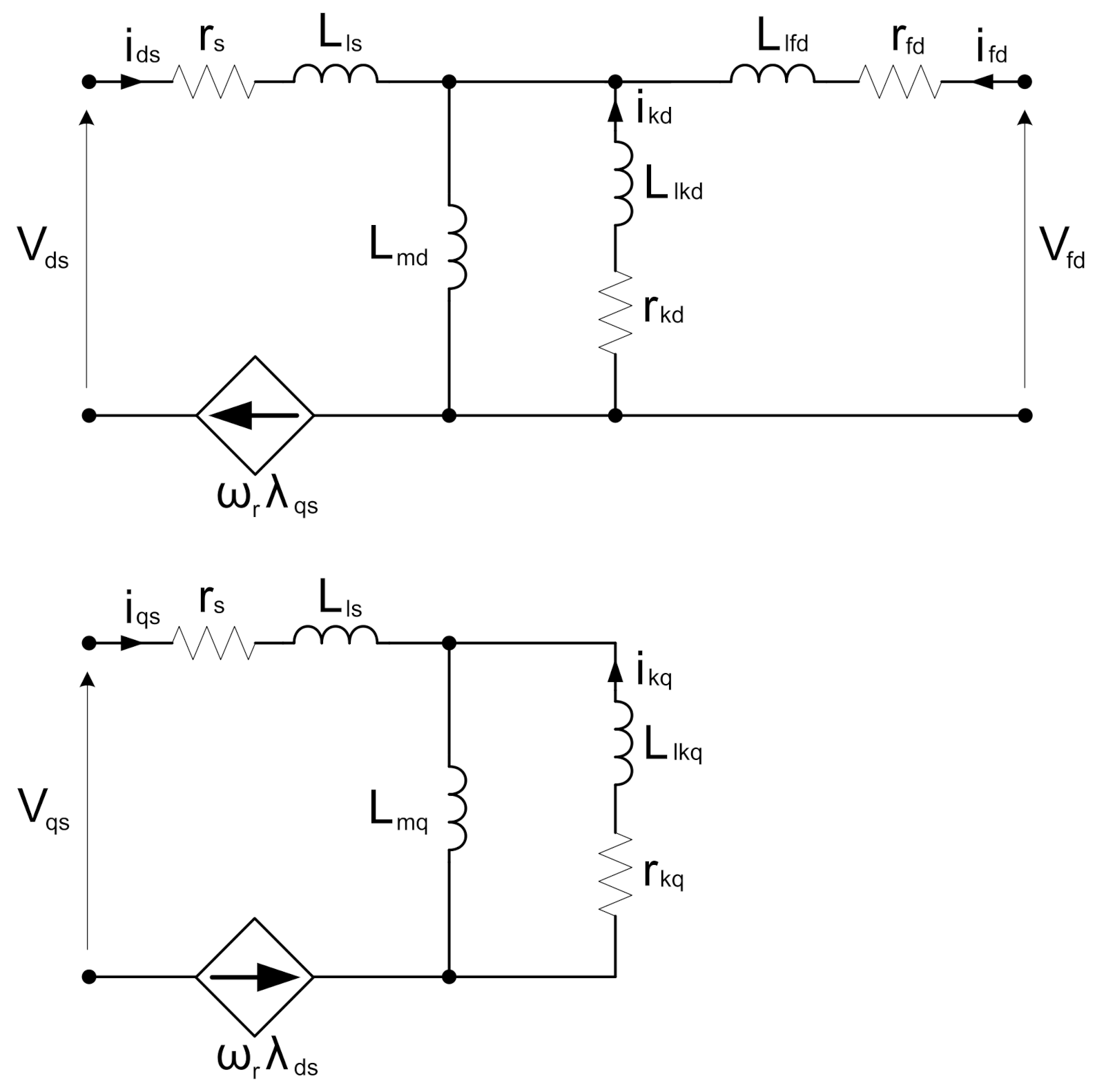
The synchronous generator model used for the PHIL application is the classical d, q model described in [
17] and shown in
Figure 1. Such models are relatively simple, and thus they are widely used and described in the literature [
18,
19,
20,
21].
The differential Equation (
1) describing the above equivalent circuits was rewritten in the MATLAB/Simulink environment in the discrete form. The parameters of the model were identified in the frequency domain using the Standstill Frequency Response (SSFR) test [
22,
23] and the least-squares problem procedures. The identified equivalent circuit parameters in [p.u.] are presented in
Appendix B.
The flux linkages are given by the equation system (
2).
The mechanical behaviour of the driving machine and the generator unit is described by Equations (
3) and (
4), where
is the driving torque set by the proportional-integral (PI) regulator.
is the electromagnetic torque and
is the friction coefficient.
J is the inertia coefficient and
p is the number of pole pairs.
One of the common issues that arise during real-time model building is the presence of algebraic loops. Indeed, in the synchronous generator mathematical model, the flux linkages
depend on the machine currents
i, while to calculate the currents, one has to know the linkages values. Such a situation can be usually solved by breaking the loops using delay blocks
. Unfortunately, in some cases, even if this solution works for MATLAB/Simulink simulations, it provokes instability while compiling the model to C language. Therefore, the authors propose a different approach consisting of rewriting the Equation (
1) in MATLAB/Simulink using integration blocks instead of differential ones. Thus, the damper bars flux leakages are calculated using Formula (
5) while the damper bars currents are calculated using Formulas (
6) and (
7).
In that case, adding the delay blocks does not result in numerical model instability.
2.2. Machine Emulation
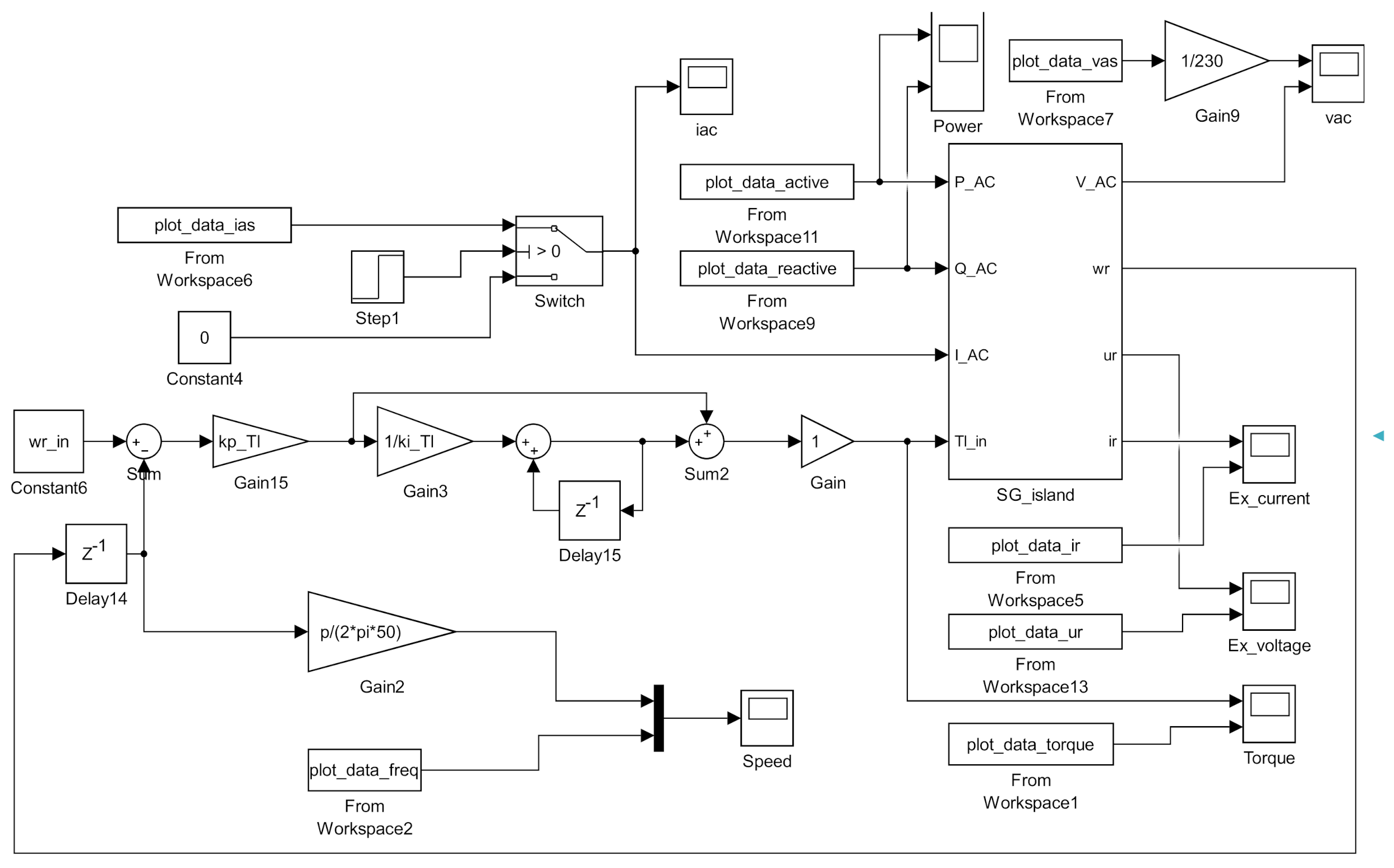
Generator model prepared in the MATLAB/Simulink environment (
Figure 2) was integrated into the real-time control algorithm of the DC/AC converter (FW functional unit). The general algorithm parameters, including the generator rated data, are configured by editing the m-file containing the set of initial variable values necessary for the operation of the functional unit controller (FUC). Then, these parameters are loaded into Workspace memory in MATLAB. After compiling the model in the Simulink environment with the parameters loaded previously, the resulting C program is automatically loaded to the functional unit controller.
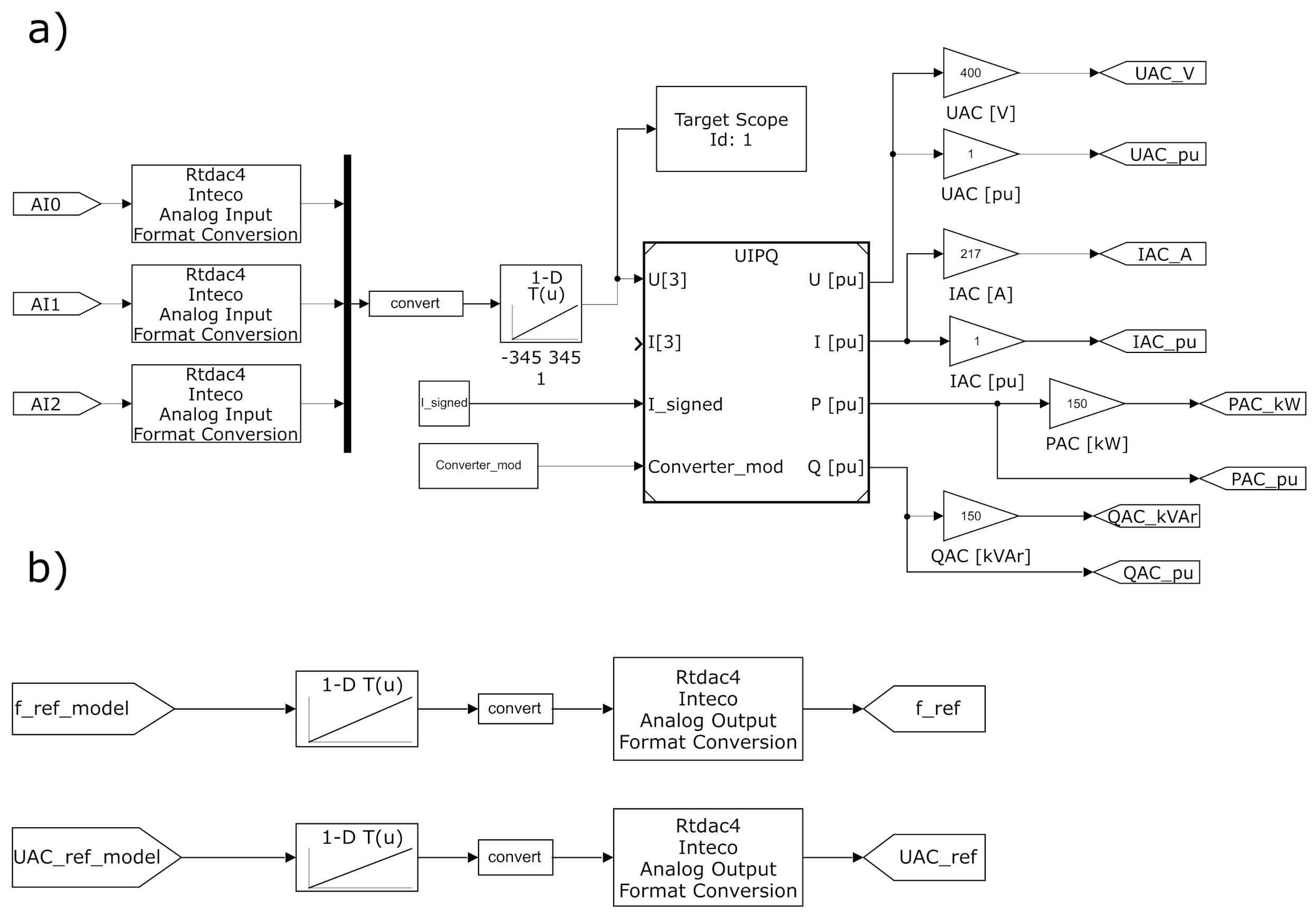
The real-time model calculation step was set to 1 ms. In each time interval, the AC phase voltages, line currents, converter frequency and DC voltage were measured by the RTDAC4 I/O card within the FUC. Raw sampled values were converted, scaled and used to calculate RMS line current, voltage and the active and reactive power (
Figure 3a). Those quantities were then fed into the generator model as inputs for the calculation of the RMS line voltage and frequency based on the mechanical speed
. At the same time, the field voltage and current from the MATLAB/Simulink generator model were also calculated. The reference values at the output of the generator model in the range of 0 to 1 were scaled to the appropriate voltage level and then converted to UINT16 variable type. Following the above mentioned operations, the values were sent to the RTDAC analogue output channels (
Figure 3b) and fed to the FW DC/AC inverter.
In the proposed approach, the inverter input parameters are typical set values for a commercial-grade inverter, such as the AC output voltage amplitude and frequency. For the frequency or the rotational mechanical speed
, a simple prime mover PI regulator was used. The output frequency of the model is dependent on the regulator parameters, the electromagnetic torque calculated based on (
4) and the combined machine moment of inertia
J.
3. Experimental Setup
3.1. Dynamometer Test Bench
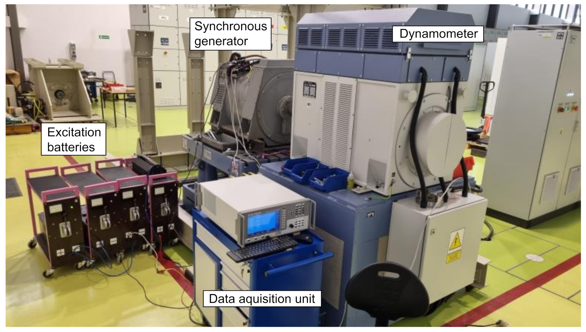
The performance of a discreet electromechanical model of synchronous generator working in autonomous power system was compared with the experimental results of the Elmor GCh114a/4 3-phase, 4-pole, 125 kVA (0.8 pf), 400 V (wye-connected) salient pole synchronous machine (rated data in
Appendix A). On load transients and steady-states were measured using a dynamometer test bench with speed and torque control (
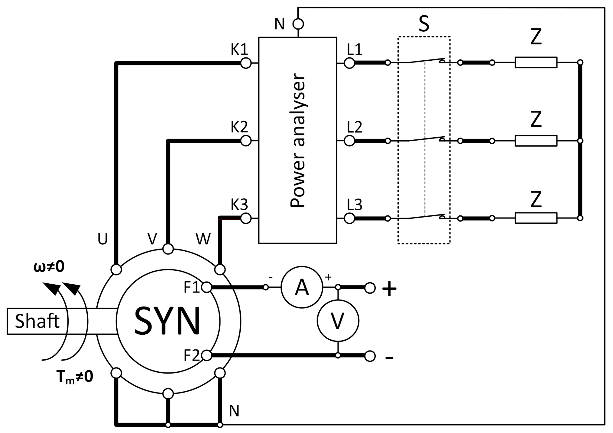
Figure 4). The diagram of the measurement setup is presented in
Figure 5. Measurements of voltages and currents during resistive and inductive loads (100 kW and 20 kVar at 400 VAC) connections were acquired using LEM
® current transducers and the ZES ZIMMER LMG670 power analyser.
3.2. PHIL System Description
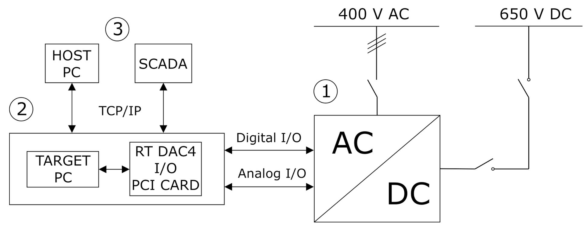
After the experimental validation, a synchronous machine model was implemented into the Power-Hardware-In-the-Loop system. The PHIL hardware consisted of three main groups of components, which are presented in
Figure 6.
The behaviour of actual synchronous generator working in isolated, island-like power system was replicated by the 150 kVA bidirectional DC/AC converter (Functional Unit (FU)), which was connected to the rest of the power system by three-phase 400 V AC bus on one side and to a 650 V DC bus on the other. The DC/AC converter marked as 1 in
Figure 6 acted as the sole energy source (a generator) for the other functional units (active and reactive loads) described in this research.
Transient states occurring after switching on and off the load connected to the converter could imitate the autonomous power generation system performance, where voltage and frequency variations are common phenomena. The functional unit was governed by a Functional Unit Controller (FUC), marked as 2 in
Figure 6. The FUC includes a 64-bit Intel PC with off-the-shelf components mounted in a 19” rack chassis (Target PC in
Figure 6). This runs the Simulink Real-Time kernel and executes the real-time control algorithm for the functional unit. In order to be able to interface with the DC/AC converter, the FUC is equipped with a measurement and control card (RT DAC4 I/O PCI CARD in
Figure 6).
This enables necessary analogue input channels for measuring phase currents, voltages, converter frequency and DC voltage. Binary states informing about the present status of the unit are also monitored. Finally, there are provided analogue and digital outputs that send reference values of AC voltage, frequency and work-mode into the converter. Host PC, marked as 3 in
Figure 6, is used for algorithm development and control through Simulink Real-Time Explorer. The SCADA environment ensures control over the whole power system described in the following paragraph.
The power electronics and real-time simulators used in this research are part of the LINTE laboratory of the Gdańsk University of Technology (Poland). This is an R&D structure designed to emulate a modern power distribution system—albeit on a reduced scale. LINTE installation includes so-called functional units responsible for: autonomous power generation, the emulation of power sources, the emulation of HV and MV transmission lines, energy storage, a transformation of energy, EVs charging and emulation of consumer loads.
Those units can be set up thanks to purpose-built switchgear, including AC and DC buses, contactors and circuit breakers accessed via IEC 61850 protocol. Each of the functional units is governed by a functional unit controller (Target PC in terms of the real-time simulation). The real-time algorithms can be used and edited individually for each of the controllers, by a Simulink-Real-Time Explorer or through the SCADA control system.
The experimental validation of the PHIL model was conducted using three functional units. The synchronous generator model was employed on a bidirectional DC/AC converter (FW) operating as a voltage source. The unit was the sole energy source with regulated voltage amplitude and frequency in the modelled autonomous power system. The FW was supplied through a DC bus with 650 V using an additional AC/DC converter, which is a part of the battery storage functional unit (BA). The BA converter was powered from the main AC bus with 400 V. To test the behaviour of the model under different scenarios the FW was connected with the LOAD4 unit, which presented a passive resistive and/or inductive load to the modelled generator. The SCADA connection diagram is presented in
Figure 7.
4. PHIL Emulator Validation
The MATLAB/Simulink model was verified by comparing its electric behaviour with the measurements performed on the 125 kVA synchronous generator. This model was used to set up in real-time the output voltage and frequency of the converter FW. Finally, the PHIL emulator of the generator unit was validated.
A series of tests with the different load characteristics (active, reactive and active-reactive) and values were conducted to investigate the dynamic behaviour of the proposed PHIL model. Three sets of data points were compared: the measurements on the SG, simulation model power converter setpoint calculated based on the measured load current and active and reactive power, and measurements of the FW converter output voltage and frequency.
Figure 8 shows an overall simplified diagram of the three sets of data points compared in this section.
Moreover, the tests included both switching the load on and off. The load applied to the machine and the emulation system had 100 kW of active power at 400 V and 20 kVar of reactive power at 400 V.
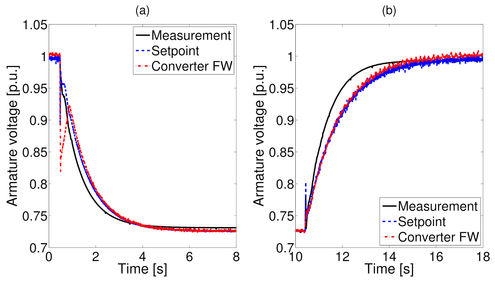
Figure 9 shows the armature voltage during (a) the load being connected and (b) the load being disconnected. The armature voltage drop is caused by the lack of an Automatic Voltage Regulator (AVR). In general, values calculated using the model implemented in the PHIL system are used as the set points for the converter. Generally, the difference between the simulation setpoint and the converter output is insignificant and results from the internal converter regulators and interference issues.
The difference between the PHIL model and the SG measurements can be explained by the model overall simplifications: lack of saturation effect implemented in the model, simplified single d and q axis reactances modelling the damper rotor winding and simplified model of the excitation power source developed using only the voltage source and internal resistance. Those simplifications influence the behaviour of the PHIL system in transient states.
Moreover, dynamic changes of the setpoint values calculated using the model, with the internal limitations of the FW converter influence the converter output. It can be observed especially in the voltage during the load connection transient, when sudden change in system load impedance causes a drop in the converter output voltage. This is a limiting factor for the use of a commercial-grade converter as a power amplifier in such a PHIL system.
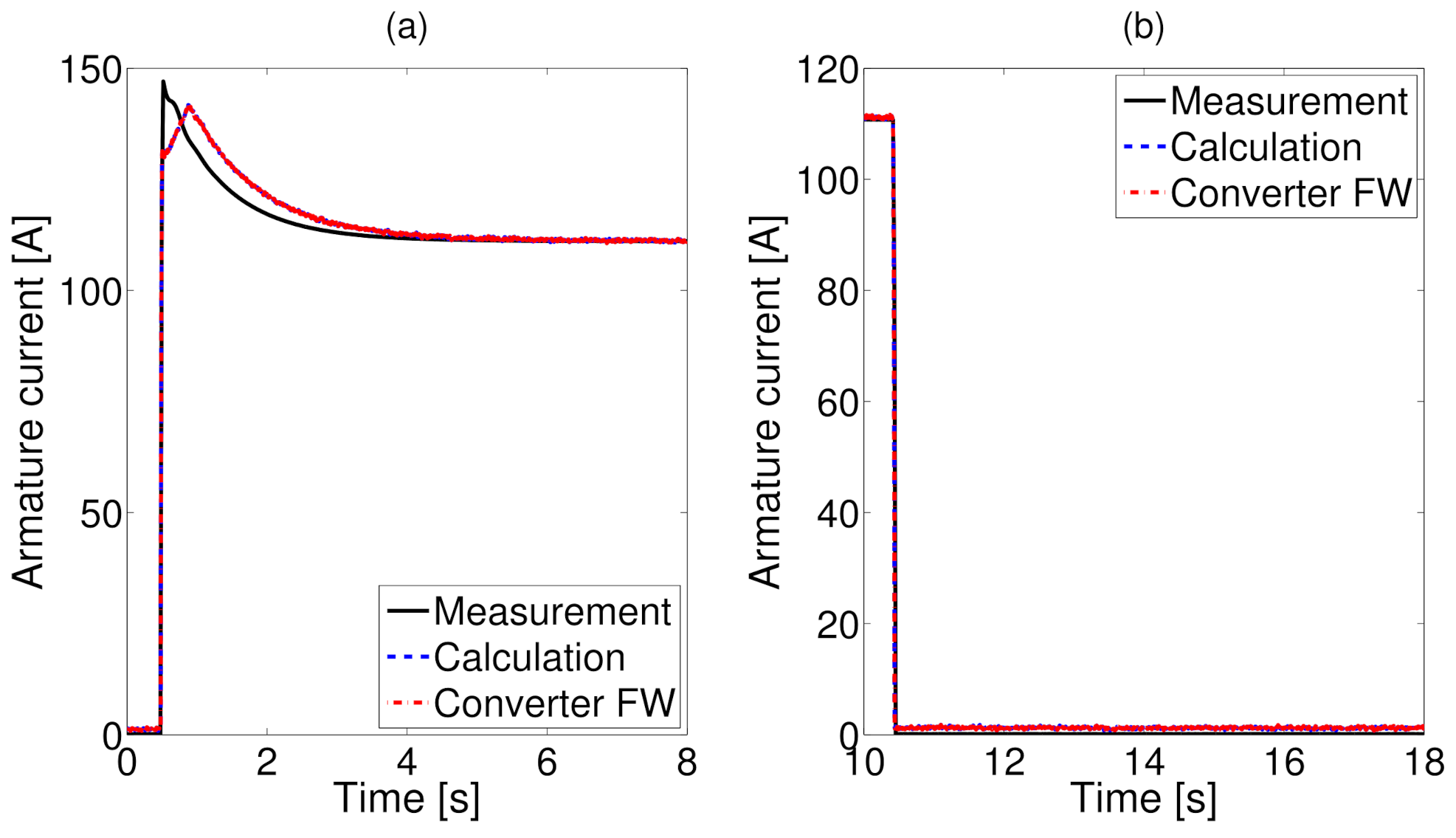
Figure 10 shows the armature current of the SG and its emulation system values. The power load disconnection in both the emulation and measurements occurs very similarly and is due to the fact that, in both cases, the current is controlled by a switch. The error observed for the time from 0.5 to 1 s is determined by the FW converter capabilities and observed for the time from 1 to 3 s is determined by the model simplifications.
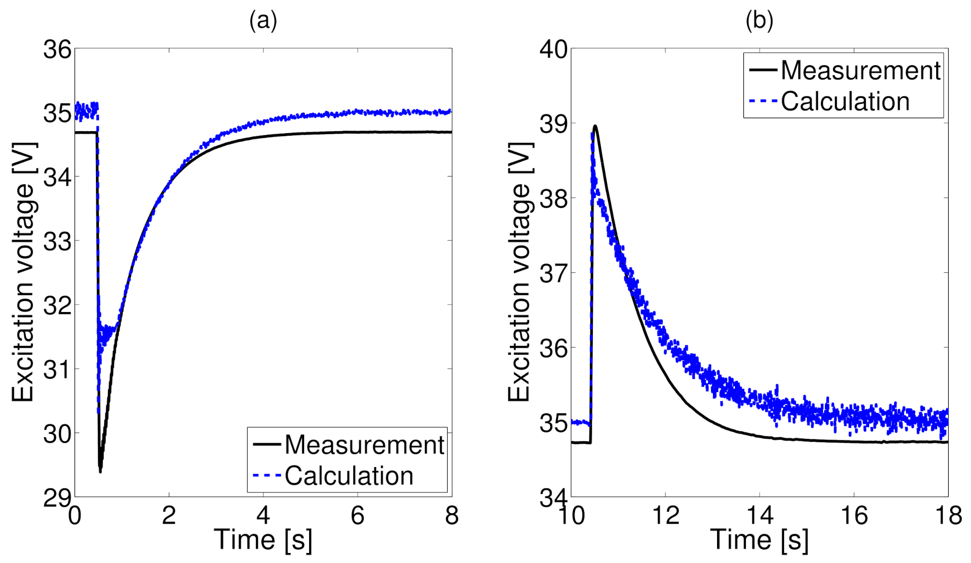
The excitation voltage and current during load connection and load disconnection are shown in
Figure 11 and
Figure 12, respectively. In this case, one can only compare two data sets, the measurements of the SG and the simulation results. The model being the part of the PHIL system calculates all of the internal machine variables, such as the excitation, armature and damper winding currents, voltages and magnetic fluxes. However, only the armature voltage and frequency are the input values of the FW converter. The other variables are the model calculation results made using actual measured armature current, active and reactive powers.
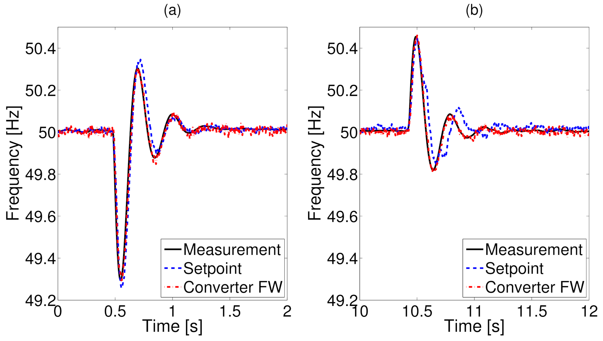
Figure 13 shows the SG armature voltage frequency. In this figure, one can see that, during the load connection, both the measurements and emulation values are very similar. However, during the load disconnection, there are some differences between the setpoint and the actual output frequency of the FW converter. The observed differences are due to the model simplification. In this case, the SG measurements were carried out using a dynamometer test stand with its own closed loop control system. The simulations were carried out using simple PI speed regulator model. However, the dynamometer may be equipped with more sophisticated control system with different or changing regulator parameters.
Despite some inaccuracies in the transient states, the presented waveforms show high compliance of the emulation with the measurements. The noise observed in the calculated curves is due to the fact that the values are calculated using measurements (active power, reactive power and line current) acquired by the online acquisition system of the PHIL model. The calculated values are then used for setting up the emulating converter. Nevertheless, the designed PHIL model of the synchronous generator reflects, to a large extent, the electrical and mechanical behaviour of the real machine.
5. Conclusions and Perspectives
The proposed PHIL approach for the emulation of the autonomous power generation system was validated in the presented research. Implemented synchronous generator model simplifications allowed for accurate real-time simulations. Variations of the output voltage amplitude and frequency observed in the generator PHIL model represent the real behaviour and performance of the machine in transient and steady states. Parameters of the model determine, to a large extent, the electrical and electromechanical performance of the synchronous generator emulator.
The model was developed and implemented in the MATLAB/Simulink environment using discrete-type function blocs. This allowed for the model to be compiled into the C language and implemented in the Real-Time Unit of the dedicated PC.
The presented results prove the usefulness of the PHIL modelling technique for the design and analysis of the autonomous power generation system. The implemented model is versatile and scalable, which allows for the application of different load levels and load characteristics. In summary, the main advantage is the possibility of using a standard power converter as the power amplifier eliminating the need for expensive and complex dedicated emulation systems. The main drawback of the presented model is the lack of magnetic saturation representation in the model parameters.
Due to the nature of the autonomous operation of the generation system, the machine magnetizing flux and terminal voltage can change in transient states, thus, influencing the nonlinear parameters of the model. In the research, the generator was not equipped with an Automatic Voltage Regulator (AVR); therefore, after applying the active and/or reactive load, the steady-state armature voltage level remained decreased.
The presented model will be further developed to incorporate additional physical phenomena, such as eddy currents in massive parts of the rotor or damper bars and magnetic saturation [
24]. Moreover, further research will also include the analysis and measurements of a diesel generator unit equipped with the AVR. Finally, the PHIL approach will be used in the synchronous generator diagnostic system, supporting the fault-condition detection in generator performance.
Author Contributions
Conceptualization, S.R. and F.K.; methodology, S.R. and F.K.; software, F.K. and Ł.S.; validation, S.R., F.K. and Ł.S.; formal analysis, S.R. and F.K.; investigation, S.R., F.K. and Ł.S.; resources, S.R. and F.K.; data curation, S.R., F.K. and Ł.S.; writing—original draft preparation, S.R. and F.K.; writing—review and editing, S.R and Ł.S.; visualization, S.R. and Ł.S.; supervision, S.R. and F.K.; project administration, S.R. and F.K.; funding acquisition, S.R. All authors have read and agreed to the published version of the manuscript.
Funding
This research was funded by the National Science Centre Poland, grant number DEC-2020/04/X/ST8/00593.
Institutional Review Board Statement
Not applicable.
Informed Consent Statement
Not applicable.
Data Availability Statement
Not applicable.
Conflicts of Interest
The authors declare no conflict of interest. The founders had no role in the design of the study; in the collection, analyses, or interpretation of data; in the writing of the manuscript, or in the decision to publish the results.
Abbreviations
The following abbreviations are used in this manuscript:
| AVR | Automatic Voltage Regulator |
| BESS | Battery Energy Storage Systems |
| DAC | Digital Analog Converter |
| DSP | Digital Signal Processors |
| ESA | Electrical Signature Analysis |
| EV | Electric Vehicle |
| FPGA | Field-Programmable Gate Array |
| FUC | Functional Unit Controller |
| HIL | Hardware-In-the-Loop |
| HV | High Voltage |
| MCSA | Motor Current Signature Analysis |
| MV | Medium Voltage |
| PHIL | Power Hardware-In-the-Loop |
| PI | Proportional-Integral |
| PMS | Power Management Systems |
| SCADA | Supervisory Control And Data Acquisition |
| SG | Synchronous Generator |
| SSFR | Standstill Frequency Response |
Appendix A
Synchronous generator Elmor GCh114o/4 rated data:
Frequency: fn = 50 Hz
Voltage: Un = 400 V
Power: Sn = 125 kVA
Appendix B
Identified equivalent circuits parameters in [p.u.] of the Elmor GCh114o/4 synchronous generator seen from the stator side:
rs = 0.033
Lls = 0.0004
Lmd = 0.0034
Lmq = 0.0016
Llkd = 1.1111
Llkq = 1.0063
rkd = 0.3
rkq = 0.8
Llfd = 1.0303
rfd = 0.0018
Base values:
Frequency: Hz
Pulsation: rad/s
Impedance:
Inductance: H.
References
- Noon, J.; Song, H.; Wen, B.; Burgos, R.; Cvetkovic, I.; Boroyevich, D.; Srdic, S.; Pammer, G. A Power Hardware-in-the-Loop Testbench for Aerospace Applications. In Proceedings of the 2020 IEEE Applied Power Electronics Conference and Exposition (APEC), New Orleans, LA, USA, 15–19 March 2020. [Google Scholar] [CrossRef]
- Michna, M.; Kutt, F.; Sienkiewicz, Ł.; Ryndzionek, R.; Kostro, G.; Ński, D.K.; Grochowski, B. Mechanical-Level Hardware-In-The-Loop and Simulation in Validation Testing of Prototype Tower Crane Drives. Energies 2020, 13, 5727. [Google Scholar] [CrossRef]
- Maneiro, J.; Ryndzionek, R.; Lagier, T.; Dworakowski, P.; Buttay, C. Design of a SiC based triple active bridge cell for a multi-megawatt DC-DC converter. In Proceedings of the 2017 19th European Conference on Power Electronics and Applications, EPE 2017 ECCE Europe 2017, Warsaw, Poland, 11–14 September 2017. [Google Scholar] [CrossRef]
- Lee, J.S.; Choi, G. Modeling and hardware-in-the-loop system realization of electric machine drives—A review. Ces Trans. Electr. Mach. Syst. 2021, 5, 194–201. [Google Scholar] [CrossRef]
- Hu, J.; Li, B.; Li, S.; Xu, Z.; Han, L.; Xu, D. High Bandwidth and High Voltage Hybrid Power Amplifier Design for PHIL. In Proceedings of the Energy Conversion Congress and Exposition—Asia, ECCE Asia 2021, Singapore, 24–27 May 2021; pp. 1648–1653. [Google Scholar] [CrossRef]
- Jha, K.; Mishra, S.; Joshi, A. Boost-Amplifier-Based Power-Hardware-in-the-Loop Simulator. IEEE Trans. Ind. Electron. 2015, 62, 7479–7488. [Google Scholar] [CrossRef]
- Du, Y.; Su, J.; Mao, M.; Yang, X. Autonomous controller based on synchronous generator dq0 model for micro grid inverters. In Proceedings of the 8th International Conference on Power Electronics—ECCE Asia: “Green World with Power Electronics”, ICPE 2011-ECCE Asia, Jeju, Korea, 30 May–3 June 2011; pp. 2645–2649. [Google Scholar] [CrossRef]
- Yang, L.; Wang, J.; Ma, Y.; Wang, J.; Zhang, X.; Tolbert, L.M.; Wang, F.F.; Tomsovic, K. Three-phase power converter-based real-time synchronous generator emulation. IEEE Trans. Power Electron. 2017, 32, 1651–1665. [Google Scholar] [CrossRef]
- Kaarthik, R.S.; Pillay, P. Emulation of a permanent magnet synchronous generator in real-time using power hardware-in-the-loop. In Proceedings of the IEEE International Conference on Power Electronics, Drives and Energy Systems, PEDES 2016, Trivandrum, Indian, 14–17 December 2016; pp. 1–6. [Google Scholar] [CrossRef]
- Barragán-Villarejo, M.; de Paula García-López, F.; Marano-Marcolini, A.; Maza-Ortega, J.M. Power System Hardware in the Loop (PSHIL): A Holistic Testing Approach for Smart Grid Technologies. Energies 2020, 13, 3858. [Google Scholar] [CrossRef]
- Mutarraf, M.U.; Terriche, Y.; Niazi, K.A.K.; Vasquez, J.C.; Guerrero, J.M. Energy Storage Systems for Shipboard Microgrids—A Review. Energies 2018, 11, 3492. [Google Scholar] [CrossRef] [Green Version]
- Torres, F.A.; Aimacana, E.; Vaca-Urbano, F.; Falcone, S.; Rengifo, J. Nonlinear AVR Control Algorithm for Synchronous Generator Using OPAL-RT. In Proceedings of the 2019 IEEE 4th Ecuador Technical Chapters Meeting, ETCM 2019, Guayaquil, Ecuador, 13–15 November 2019. [Google Scholar] [CrossRef]
- Tierney, D.; Kasztenny, B.; Finney, D.; Haas, D.; Le, B. Performance of generator protection relays during off-nominal frequency operation. In Proceedings of the 2014 67th Annual Conference for Protective Relay Engineers, CPRE 2014, College Station, TX, USA, 31 March–3 April 2014; pp. 450–469. [Google Scholar] [CrossRef]
- Salah, M.; Bacha, K.; Chaari, A.; Benbouzid, M.E.H. Brushless three-phase synchronous generator under rotating diode failure conditions. IEEE Trans. Energy Convers. 2014, 29, 594–601. [Google Scholar] [CrossRef]
- Nandi, S.; Toliyat, H.A.; Li, X. Condition monitoring and fault diagnosis of electrical motors—A review. IEEE Trans. Energy Convers. 2005, 20, 719–729. [Google Scholar] [CrossRef]
- Yucai, W.; Yonggang, L. Diagnosis of rotor winding interturn short-circuit in turbine generators using virtual power. IEEE Trans. Energy Convers. 2015, 30, 183–188. [Google Scholar] [CrossRef]
- Krause, P.C.; Wasynczuk, O.; Sudhoff, S.D. Analysis of Electric Machinery and Drive Systems, 3rd ed.; Wiley-IEEE Press: New York, NY, USA, 2013. [Google Scholar] [CrossRef]
- Wamkeue, R.; Kandil, N.; Berrada, M. Equivalent circuit based current-controlled state model of synchronous machine. In Proceedings of the 4th International Power Electronics and Motion Control Conference, Xi’an, China, 14–16 August 2004; Volume 3. [Google Scholar]
- Radjeai, H.; Abdessemed, R.; Tnani, S.; Mouni, E. A method to improve the synchronous machines equivalent circuits. In Proceedings of the EUROCON 2007—The International Conference on Computer as a Tool, Warsaw, Poland, 9–12 September 2007; pp. 2367–2372. [Google Scholar] [CrossRef]
- Hiramatsu, D.; Uemura, Y.; Okumoto, J.; Uemoto, S.; Imai, T.; Kakiuchi, M.; Nagakura, K.; Otaka, T.; Fujita, M.; Nagasaka, K. A study on quadrature equivalent circuit model in large synchronous machine. In Proceedings of the IEEE Power and Energy Society 2008 General Meeting: Conversion and Delivery of Electrical Energy in the 21st Century, PES, Pittsburgh, PA, USA, 20–24 July 2008. [Google Scholar] [CrossRef]
- Ma, Y.; Zhou, L.; Wang, J.; Cui, Y.; Cai, W.; Zhao, J. Accurate equivalent circuit modeling and identification of solid rotor synchronous machine. In Proceedings of the 1st IEEE Student Conference on Electric Machines and Systems, SCEMS 2018, Busan, Korea, 1–3 November 2019. [Google Scholar] [CrossRef]
- IEEE Std 115-1995; IEEE Guide for Test Procedures for Synchronous Machines Part I—Acceptance and Performance Testing Part II—Test Procedures and Parameter Determination for Dynamic Analysis. IEEE: New York, NY, USA, 2010. [CrossRef]
- Racewicz, S.; Kutt, F.; Michna, M.; Sienkiewicz, Ł. Comparative Study of Integer and Non-Integer Order Models of Synchronous Generator. Energies 2020, 13, 4416. [Google Scholar] [CrossRef]
- Racewicz, S.; Riu, D.M.; Retière, N.M.; Chrzan, P.J. Half-order modeling of saturated synchronous machine. IEEE Trans. Ind. Electron. 2014, 61, 5241–5248. [Google Scholar] [CrossRef]
Figure 1.
Classical equivalent circuits of a synchronous generator connected to RL electric load (axes d and q).
Figure 1.
Classical equivalent circuits of a synchronous generator connected to RL electric load (axes d and q).
Figure 2.
MATLAB/Simulink I/O signals of the synchronous generator model emulated by the converter.
Figure 2.
MATLAB/Simulink I/O signals of the synchronous generator model emulated by the converter.
Figure 3.
(a) Example of input signal path present in the FUC algorithm for the calculation of RMS voltages, currents, active and reactive power; (b) example of the analogue output scaling and conversion for the reference values of phase voltage and converter frequency within the FUC algorithm.
Figure 3.
(a) Example of input signal path present in the FUC algorithm for the calculation of RMS voltages, currents, active and reactive power; (b) example of the analogue output scaling and conversion for the reference values of phase voltage and converter frequency within the FUC algorithm.
Figure 4.
Measurement setup with the dynamometer and the studied synchronous generator.
Figure 4.
Measurement setup with the dynamometer and the studied synchronous generator.
Figure 5.
Diagram of measurement setup for synchronous generator resistive and inductive on-load transient tests.
Figure 5.
Diagram of measurement setup for synchronous generator resistive and inductive on-load transient tests.
Figure 6.
Block diagram of the PHIL system, including: (1) DC/AC bidirectional converter—Functional unit (FU), (2) Functional Unit Controller (FUC) and (3) Communication and control peripherals.
Figure 6.
Block diagram of the PHIL system, including: (1) DC/AC bidirectional converter—Functional unit (FU), (2) Functional Unit Controller (FUC) and (3) Communication and control peripherals.
Figure 7.
Diagram of the LINTE laboratory functional units used in the PHIL testing of the synchronous generator model.
Figure 7.
Diagram of the LINTE laboratory functional units used in the PHIL testing of the synchronous generator model.
Figure 8.
Diagram of the measured and acquired sets of data points from (a) SG measurements and (b) the emulation system.
Figure 8.
Diagram of the measured and acquired sets of data points from (a) SG measurements and (b) the emulation system.
Figure 9.
Comparison of the measured, calculated and emulated armature voltage of the synchronous generator during active–reactive load switched on (a) and off (b).
Figure 9.
Comparison of the measured, calculated and emulated armature voltage of the synchronous generator during active–reactive load switched on (a) and off (b).
Figure 10.
Comparison of the measured, calculated and emulated armature current of the synchronous generator during active-reactive load switched on (a) and off (b).
Figure 10.
Comparison of the measured, calculated and emulated armature current of the synchronous generator during active-reactive load switched on (a) and off (b).
Figure 11.
Comparison of the measured and calculated excitation voltage of the synchronous generator during active-reactive load switched on (a) and off (b).
Figure 11.
Comparison of the measured and calculated excitation voltage of the synchronous generator during active-reactive load switched on (a) and off (b).
Figure 12.
Comparison of the measured and calculated excitation current of the synchronous generator during active-reactive load switched on (a) and off (b).
Figure 12.
Comparison of the measured and calculated excitation current of the synchronous generator during active-reactive load switched on (a) and off (b).
Figure 13.
Comparison of the measured, calculated and emulated output frequency of the synchronous generator during active-reactive load switched on (a) and off (b).
Figure 13.
Comparison of the measured, calculated and emulated output frequency of the synchronous generator during active-reactive load switched on (a) and off (b).
| Publisher’s Note: MDPI stays neutral with regard to jurisdictional claims in published maps and institutional affiliations. |
© 2022 by the authors. Licensee MDPI, Basel, Switzerland. This article is an open access article distributed under the terms and conditions of the Creative Commons Attribution (CC BY) license (https://creativecommons.org/licenses/by/4.0/).


