Article

LambertW Function to Extract Physical Parameters of a Schottky Barrier Diode from Its I–V Characteristics

by
Safae Aazou
1,2,*,
Matthew Schuette White
3,
Martin Kaltenbrunner
4,5,
Zouheir Sekkat
1,2,
Daniel Ayuk Mbi Egbe
6,7 and
El Mahdi Assaid
8
1
Faculty of Sciences, Mohammed V University in Rabat, B.P. 1014 RP Rabat, Morocco
2
Moroccan Foundation for Advanced Science Innovation and Research (MAScIR)-UM6P, B.P. 10100 Rabat, Morocco
3
Department of Physics, University of Vermont, Burlington, VT 05405, USA
4
Soft Matter Physics, Institute of Experimental Physics, Johannes Kepler University, A-4040 Linz, Austria
5
LIT Soft Materials Lab, Johannes Kepler University, A-4040 Linz, Austria
6
Energieinstitut an der Johannes Kepler Universität, Altenbergerstraße 69, 4040 Linz, Austria
7
College of Science and Technology, University of Rwanda, KN 7 Ave, Kigali P.O. Box 3900, Rwanda
8
Faculty of Sciences, University Chouaïb Doukkali, B.P. 24000 El Jadida, Morocco
*
Author to whom correspondence should be addressed.
Energies 2022, 15(5), 1667; https://doi.org/10.3390/en15051667
Submission received: 7 November 2021 / Revised: 21 December 2021 / Accepted: 26 December 2021 / Published: 23 February 2022

Abstract

:
In the current work, the exact analytical expression of the current–voltage characteristics, which are given in terms of the L a m b e r t W function, is used to extract the physical parameters of organic and inorganic Schottky barrier diodes (SBDs). The extraction is achieved by a variety of methods using the experimental I–V characteristics. The organic SBD is based on a Poly (3-hexylthiophene-2,5-diyle) conjugated polymer (P3HT) with Al contact, measured at 300 K. Regarding the inorganic SBDs, one is based on Iridium–Silicon Carbide (Ir–SiC), measured at 300 K, and the second diode is based on Gold–Gallium Arsenide (Au–GaAs), measured at 200 K. The numerical characteristics based on the physical parameters extracted by the presented methods are in good agreement with the experimental data. The determination coefficient of the modeling methods for the three SBDs is higher than 99.99%.

1. Introduction

Schottky barrier diodes are metal semiconductor contacts or organic-inorganic semiconductor contacts. In modern electronics, SBDs are promising structures that are used in the majority of semiconductor components [1,2]. They are a rectifying contacts that appear when the work function of the p-type semiconductor is higher than the work function of the metal. For the n-type metal-semiconductor contact, the work function of the semiconductor must be lower than that of the metal. A good Schottky contact gives rectifying current–voltage characteristics, which allows the current to flow in forward and be blocked in reverse. Despite their simple structure, SBDs are interesting in the design and manufacturing process. They are widely used in a vast number of devices [3,4,5,6]. Indeed, SBDs are used in photovoltaic devices, in integrated circuits and in many semiconductor compounds, such as chemical sensors, electronic and electrochromic devices and non-linear optics, bringing meaningful benefits over silicone counterparts [7,8,9,10,11,12]. Despite the many advantages of this technology, there is a lack of knowledge in process fabrication, which attracts enormous research interest. As a consequence, a full understanding of their physics and a good knowledge of their electrical properties are of great interest. A large number of theoretical and experimental studies have been performed to extract SBDs’ physical parameters. The model parameters are extracted by different types of methods and can be divided into the following families:
  • Approximation methods [13,14,15,16,17]: they are fast, simple and do not require tedious numerical calculations. However, they are not able to determine all the parameters at once, and they do not cover the whole range of the voltage.
  • Optimization methods: these include vertical optimization [18,19], lateral optimization [20] and differential evolution [21]. These methods employ the entire range of the voltage to simultaneously extract all the physical parameters. Nevertheless, they do not take into account the effect of the shunt resistance. Moreover, they require high computation loads and they also require the introduction of initial values.
In this study, we model organic and inorganic SBDs with an electronic circuit with four physical parameters, a photodiode with its reverse saturation current I s , its ideality factor η , both parasitic series R s and shunt R s h resistances. In a previous work, researchers extracted some parameters of an organic SBD with comparison to inorganic SBDs using different approximation and optimization procedures [22]. The starting point of our work, for all the used methods, is the analytical solution of the transcendental equation expressed in terms of the L a m b e r t W function [23,24,25]. Following the proposed methods, all physical parameters are determined at once without any approximation and by exploiting the full range of voltage. The first method implements the analytical expression of dynamical conductance. The second method is based on the current analytical expression integration. The last method utilizes a specific function in the Mathematica software [26]. This method is applied for different compounds described by this specific function L a m b e r t W . This later gives the exact analytical solution of the current flowing through the diode in terms of the voltage and the physical parameters in the diode model, including solar cells [24,27], transistors [23,28], and light emitters [29,30].
The I V characteristics determined from the parameters extracted are in good agreement with experiments. The determination coefficient R 2 is calculated for the three methods presented to extract the four SBD parameters, and it is higher than 99.99%. How we calculate R 2 is given in our supplementary materials [31,32,33]. The experimental details of preparing the organic SBD is given in the supplementary material, we used the same process, with different recipes, to elaborate organic devices [34,35]. The experimental data of the inorganic SBDs are from reference [36]. The current–voltage characteristics for the gold–gallium arsenide SBD is measured at a temperature of 200 K to show that the method can be applied at different temperatures and to check the behaviour of the device at different temperatures [36]. V. Kumar et al. studied the effect of temperature on the I–V characteristics of the N i / 4 H n S i C (0001) SBD temperature sensor [37]. They analyzed the I–V–T characteristics with variation of the barrier height and the ideality factor with temperature, and concluded that inhomogeneities of the barrier height at the metal-semiconductor interface led to some anomalies in the device thermal sensitivity. These same researchers studied highly sensitive and linear temperature sensors based on epitaxial silicon carbide (Si–C) with linear sensing characteristics up to the ultra-low-current range [38].

2. Basic Equations

This section is devoted to explicitly expressing the current which flows in SBDs. This is needed in order to be used in the three extraction methods.
When a Schottky barrier diode with parasitic resistances is biased, it is assumed that the device is acrossed by a current due to thermionic emission [3,39,40] and which is expressed by:
I = I s e x p V R s I η V t h 1 + V R s I R s h
where the reverse saturation current I s is given by
I s = A A * * T 2 e x p ϕ V t h
and V t h = k B T q is the thermal voltage, q is the electron elementary charge, k B is the Boltzmann constant, T is the absolute temperature, A is the diode area, A * * is the modified Richardson constant and ϕ is the Schottky barrier height.
Equation (1) is a transcendental equation that implicitly relates the current and the applied voltage. This equation may be written in the following compact form:
w e x p ( w ) = x
where:
w = R s I V η V t h + R s I s + V η V t h ( 1 + G p R s ) ,
and
x = R s I s η V t h ( 1 + G p R s ) exp R s I s + V η V t h ( 1 + G p R s )
where G p = 1 R s h is the shunt conductance.
The solution w ( x ) of Equation (3) is the multi-valued function L a m b e r t W k ( x ) [25]. In our case, the adequate branch of the L a m b e r t W function corresponds to k = 0 , which satisfies the condition L a m b e r t W 0 ( x ) = 0 for x = 0 . Then, the solution w ( x ) of Equation (3) is:
w = L a m b e r t W 0 [ x ]
which can be rewritten as:
R s I V η V t h + R s I s + V η V t h ( 1 + G p R s ) = L a m b e r t W R s I s ( 1 + G p R s ) 1 η V t h e x p R s I s + V η V t h ( 1 + G p R s )
After rearrangement, the explicit expression giving current as a function of voltage is written:
I = η V t h R s L a m b e r t W R s I s η V t h ( 1 + G p R s ) e x p R s I s + V η V t h ( 1 + G p R s ) I s V G p ( 1 + G p R s )
Similarly, the explicit expression giving voltage as a function of current is written:
V = η V t h L a m b e r t W I s G p η V t h e x p ( I + I s ) G p η V t h + I ( R s + 1 G p ) + I s G p

3. Extraction Methods

This section focuses on the three extraction methods that will be used to determine the four parameters of the SBDs.

3.1. Dynamical Conductance

The dynamical conductance method is based on fitting numerical values of d I d V calculated from experimental data to an analytical expression derived from Equation (8).
To make Equation (8) lighter, we put:
a 1 = R s I s η V t h ( 1 + G p R s ) , a 2 = R s I s , a 3 = η V t h ( 1 + G p R s ) , a 4 = η V t h R s , a 5 = I s ( 1 + G p R s ) , a 6 = G p ( 1 + G p R s ) and we note LambertW as W .
Then, Equation (8) becomes:
I = a 4 W a 1 e x p V + a 2 a 3 + a 6 V + a 5
The current derivative with respect to the voltage d I d V writes:
d I d V = a 4 d d V W a 1 e x p V + a 2 a 3 + a 6 = a 4 I a 6 V a 5 a 4 a 3 1 + I a 6 V a 5 a 4 + a 6
The reorganization of this equation leads to an expression of the voltage in terms of the dynamical conductance, the current, the voltage itself and the physical parameters:
V = α G d I d V + α I G I d I d V + α V G V d I d V + α I I + α 0
where:
α G = η V t h ( R s + 1 G p ) R s G p I s , α I G = R s ( R s + 1 G p ) , α V G = R s , α I = R s + 1 G p and α 0 = η V t h + I s G p .
With the aim of determining the physical parameters of the SBDs, the dynamical conductance is initially calculated from the experimental I–V characteristics. Then, coefficients in Equation (12) are varied in order to fit the analytical expression to dynamical conductance experimental values. The coefficient variation is stopped when the deviation between experimental and optimized values reaches a predefined precision. Afterward, the physical parameters are extracted from these coefficients:
R s = α V G = α I G α I , R s h = α I α V G = α I + α I G α I , η = α G α 0 α G α I V t h α I G + α I 2 , and I s = α 0 α G α 0 α G α I α I G + α I 2 α I + α I G α I .
The Schottky barrier height ϕ is then determined from Equation (2):
ϕ = V t h l n A A * * T 2 I s

3.2. Integral Method

The second procedure was used first by Ortiz–Conde et al. to determine the five physical parameters of an illuminated solar cell under AM1.5 [41]. We used this method in previous work to extract the physical parameters of organic-based solar cells with different polymers [34].
The integral of the current is calculated from Equation (10):
0 V I d x = P ( x ) 0 V = P ( V ) P ( 0 )
where
P V = a 4 a 3 2 W 2 a 1 e x p V + a 2 a 3 + a 6 2 a 4 V 2 + a 5 a 4 V + a 3 W a 1 e x p V + a 2 a 3
and:
P 0 = a 4 a 3 2 W 2 a 1 e x p a 2 a 3 + a 3 W a 1 e x p a 2 a 3
Equation (10) gives:
W a 1 e x p V + a 2 a 3 = I a 6 V a 5 a 4
For V = 0 , we have I = 0 . Therefore, Equation (19) becomes:
W a 1 e x p a 2 a 3 = a 5 a 4
By substituting Equations (19) and (20), respectively, in Equations (17) and (18), the integral in Equation (16) is expressed as follows:
0 V I d x = c I 1 I + c V 1 V + c I V I V + c I 2 I 2 + c V 2 V 2
where
c I 2 = a 3 2 a 4 , c V 2 = a 6 2 ( 1 + a 3 a 6 a 4 ) , c I V = a 3 a 6 a 4 , c I 1 = a 3 ( 1 a 5 a 4 ) and c V 1 = a 3 a 5 a 6 a 4 a 3 a 6 + a 5 .
To determine the physical parameters, the integral is calculated numerically from experimental I–V characteristics. Afterward, a two dimensional fitting of analytical expressions to numerical values is performed to find coefficients of Equation (21). Subsequently, the physical parameters are deduced:
R s = c I V 2 c V 2 , R s h = 1 2 c V 2 , I s = c V 1 2 c I 1 c V 2 + c V 1 c I V and η = 1 V t h c I 1 c V 1 c V I 2 c V 2 .
The Schottky barrier height ϕ is then determined from Equation (15).

3.3. FindFit Function

In this method, the magic “FindFit” function in the Mathematica Software package was called to determine SBDs physical parameters [26,36]. FindFit is usually used in statistics as a nonlinear fitting tool; it returns numerical values of the parameters ensuring that the model equation fits well to the experimental data. In linear cases, FindFit finds a globally optimal fit. However, in nonlinear cases, it finds in general only a locally optimal fit. It uses by default a least squares fit for both cases. For nonlinear problems, the “FindFit” function internally calls some methods, such as: Conjugate Gradient, Gradient, Principal Axis Method of Brent, Levenberg Marquardt, Newton, NMinimize and Quasi Newton [42].
In this method, the model equation is the analytical expression of current flowing through the device and is given by:
I = η V t h R s W R s A A * * T 2 e x p ϕ V t h η V t h ( 1 + G p R s ) e x p R s A A * * T 2 e x p ϕ V t h + V η V t h ( 1 + G p R s ) A A * * T 2 e x p ϕ V t h V G p ( 1 + G p R s )
The physical parameters are then determined by fitting Equation (24) to the experimental data.

4. Results

To obtain a better understanding of the transport mechanisms and optical processes occurring in optoelectronic devices that may control the behaviour of the Schottky diode, the knowledge of the device’s physical parameters is a must [43]. As explained, the electronic circuit modeling the SBD contains four parameters: a non-ideal diode with its saturation current I s , its ideality factor η , and parasitic resistances R s and R s h . The experimental current–voltage characteristics of the organic and inorganic SBDs are depicted with the calculated characteristics. The physical parameters are extracted with the presented methods and are shown in Table 1, Table 2 and Table 3.
The series resistance R s takes into account charge carrier mobility in the material which is governed by the presence of impurities and can also be caused by [44,45,46,47]: (i) current flow through the transmitter and the base; (ii) resistance due to the ohmic contact between the metal and the semiconductor, or; (iii) resistance due to the back metal contact.
The parallel or shunt resistance R s h is linked to edge effects and volume recombinations. It results from the leakage current through the device, around the edges and between contacts of different polarities [44,45,46,47].
The saturation current I s is the current which flows in the reverse direction when the diode is reverse biased, also called the leakage current. It is the sum of a term which is proportional to the number of electrons in the conduction band of an n-type semiconductor, and the second term is proportional to the number of holes in the valence band of a p-type semiconductor (in dark) [44,46,48].
The ideality factor η is informative of the recombination transition mechanisms that occur in the junction [46]. In the current study, the lowest series resistance is obtained for the iridium–silicon carbide-based SBD, followed by the organic SBD, then the gold–gallium arsenide-based SBD which exhibits the highest shunt resistance. The leakage current is lower for inorganic SBDs. Moreover, the ideality factor does not exceed 2 for these inorganic diodes, which means that recombination processes are negligible. Contrary to organic devices, where η is higher than 2 ( η = 5), this indicates that more complicated optical processes occur, such as extrinsic Shockley–Read–Hall generation recombination or Auger recombinations [46]. In a previous study, organic-based solar cells were shown to exhibit an ideality factor higher than 2 [34].
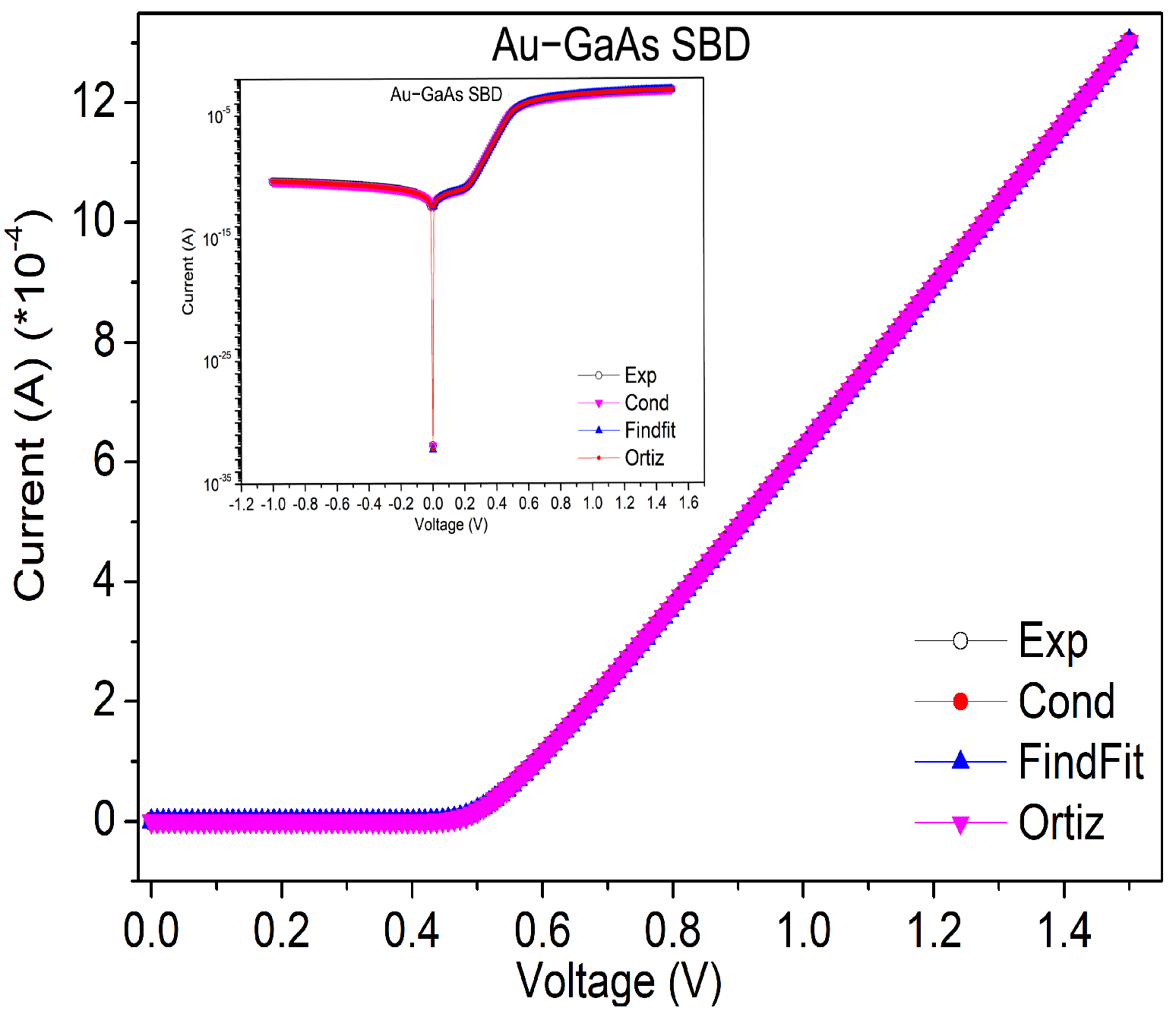
The experimental current–voltage characteristics measured for the elaborated inorganic SBD and calculated characteristics determined from the extracted parameters via dynamical conductance, integral and FindFit methods are depicted in Figure 1 and Figure 2 for Ir–SiC and Au–GaAs, respectively, with a semilogarithmic scale in the inserted figures. The deviations between the experimental data and the optimized characteristics calculated via all methods are studied, and the lowest deviation is depicted for each device in Figure 3 and Figure 4 for Ir–SiC and Au–GaAs, respectively.
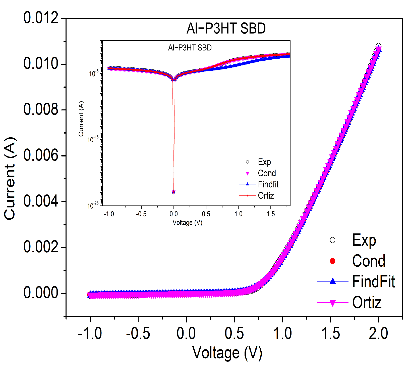
Figure 5 presents the experimental current–voltage characteristics of the organic SBD; the inserted figure shows the semi-log plot of I–V characteristics. To better check the modeled data, we calculated the deviations between optimized and experimental data, and the lowest deviation is presented in Figure 6.

5. Conclusions

In our work, we have used three techniques to determine the physical parameters of inorganic and organic SBDs. All diodes are modeled by an electronic circuit including one diode, series and shunt resistances. In the first method, we used the analytical expression of the dynamical conductance. The second method is based on analytical expression of the surface under the current-voltage characteristics. The third method consists of utilizing the FindFit procedure of the Mathematica computer algebra software to fit the analytical expression of the Schottky diode current to the experimental data.
In order to show which technique was more suitable for each SBD, we analyzed the current deviation between calculated curves and experimental data. This study shows that the FindFit technique leads to best results for the inorganic Au–GaAs-based SBD. However, for the Ir–SiC-based SBD, the lowest deviation is obtained by the integral technique. The organic diode deviation was highest with the first method, and the lowest deviation is obtained by FindFit method. These conclusions are confirmed by the calculation of the R 2 determination coefficient (the determination coefficient calculations are given in the SI). The conductance method does not depend on initial values, contrarily to Ortiz-Condé technique, where these initial values is needed.

Supplementary Materials

The following are available online at https://www.mdpi.com/article/10.3390/en1010000/S1.

Author Contributions

Conceptualization, S.A., M.S.W., M.K. and E.M.A.; Formal analysis, S.A., M.S.W., M.K., Z.S., D.A.M.E. and E.M.A.; Funding acquisition, S.A. and E.M.A.; Investigation, S.A., M.S.W., M.K., D.A.M.E. and E.M.A.; Methodology, S.A., M.S.W., M.K. and E.M.A.; Resources, D.A.M.E.; Software, S.A. and E.M.A.; Validation, S.A., M.S.W., M.K. and Z.S.; Visualization, S.A., M.S.W., M.K. and E.M.A.; Writing—original draft, S.A. and E.M.A.; Writing—review and editing, S.A., M.S.W., M.K., Z.S., D.A.M.E. and E.M.A. All authors have read and agreed to the published version of the manuscript.

Funding

This research was funded by African Network for Solar Energy (ANSOLE) and Programme Averroès III, Centre National pour la Recherche Scientifique et Technique (CNRST) of Morocco and MESFCRS PPR project PPR/2015/59 “Development of Organic Solar Cells”.

Institutional Review Board Statement

Not applicable.

Informed Consent Statement

Not applicable.

Acknowledgments

S.A. would like to deeply thank S. N. Sariciftci, director of LIOS, Kepler University, Linz, Austria, for the experiment and characterization she performed in his laboratories for the organic SBD.

Conflicts of Interest

The authors declare no conflict of interest.

References

  1. Maeda, T.; Takagi, S.; Ohnishi, T.; Lippmaa, M. Sulfur passivation of Ge (001) surfaces and its effects on Schottky barrier contact. Mater. Sci. Semicond. Process. 2006, 9, 706–710. [Google Scholar] [CrossRef]
  2. Aydoǧan, Ş.; Incekara, Ü.; Deniz, A.R.; Türüt, A. Extraction of electronic parameters of Schottky diode based on an organic Indigotindisulfonate Sodium (IS). Solid State Commun. 2010, 1592–1596. [Google Scholar] [CrossRef]
  3. Rhoderick, E.H.; Williams, R.H. Metal-Semiconductor Contacts, 2nd ed.; Clarendon Press: Oxford, UK; Oxford University Press: New York, NY, USA, 1988. [Google Scholar]
  4. Missoum, I.; Ocak, Y.S.; Benhaliliba, M.; Benouis, C.E.; Chaker, A. Microelectronic properties of organic Schottky diodes based on MgPc for solar cell applications. Synth. Met. 2010, 214, 76–81. [Google Scholar] [CrossRef]
  5. Gupta, R.K.; Singh, R.A. Fabrication and characteristics of Schottky diode based on composite organic semiconductors. Compos. Sci. Technol. 2010, 65, 677–681. [Google Scholar] [CrossRef]
  6. Keskin, B.; Denktaş, C.; Altındal, A.; Avcıata, U.; Gül, A. Synthesis of Ni(II) porphyrazine peripherally octa-substituted with the 4-tert-butylbenzylthio moiety and electronic properties of the Al/Ni(II)Pz/p-Si Schottky barrier diode. Polyhedron 2012, 38, 121–125. [Google Scholar] [CrossRef]
  7. Peumans, P.; Forrest, S.R. Very high efficiency double heterostructure copper phthalocyanine/C60 photovoltaic cells. Appl. Phys. 2001, 79, 126–128. [Google Scholar] [CrossRef]
  8. Kim, D.Y.; So, F.; Gao, Y. Aluminum phthalocyanine chloride/C60 organic photovoltaic cells with high open-circuit voltage. Sol. Energ. Mater. Sol. Cells 2009, 93, 1688–1691. [Google Scholar] [CrossRef]
  9. Pekdemir, F.; Kurnalı, S.; Şengül, A.; Altındal, A.; Özkaya, A.R.; Salih, B.; Bekaroglu, Ö. A conformationally stressed novel ball-type perylenediimide appended zinc(II)phthalocyanine hybrid: Spectro- electrochemical, electrocolorimetric and photovoltaic properties. Dalton Trans. 2009, 44, 158–166. [Google Scholar] [CrossRef]
  10. Rella, R.; Siciliano, P.; Manno, D.; Serra, A.; Taurino, A.; Tepore, A.; Valli, L.; Zocco, A. Gas-sensing properties of multilayers of two new macrocyclic copper complexes. Sens. Actuators B Chem. 1977, 44, 585–589. [Google Scholar] [CrossRef]
  11. Şahin, S.; Altun, A.; Altındal, A.; Odabaş, Z. Synthesis of novel azo-bridged phthalocyanines and their toluene vapour sensing properties. Sens. Actuators B Chem. 2015, 206, 601–608. [Google Scholar] [CrossRef]
  12. Chen, Y.; Hanack, M.; Blau, W.J.; Dini, D.; Liu, Y.; Lin, Y.; Bai, J. Soluble axially substituted phthalocyanines: Synthesis and nonlinear optical response. J. Mater. Sci. 2006, 41, 2169–2185. [Google Scholar] [CrossRef]
  13. Sze, S.M. Physics of Semiconductor Devices, 2nd ed.; Wiley: New York, NY, USA, 1981. [Google Scholar]
  14. Norde, H. A modified forward I-V plot for Schottky diodes with high series resistance. J. Appl. Phys. 1979, 50, 5052–5053. [Google Scholar] [CrossRef]
  15. Cheung, S.K.; Cheung, N.W. Extraction of Schottky diode parameters from forward current-voltage characteristics. Appl. Phys. Lett. 1986, 49, 85–87. [Google Scholar] [CrossRef]
  16. Werner, J.H. Schottky barrier and pn-junctionI/V plots—Small signal evaluation. Appl. Phys. A 1988, 47, 291–300. [Google Scholar] [CrossRef]
  17. Werner, J.H.; Guttler, J.H. Barrier Inhomogeneities at Schottky Contacts. J. Appl. Phys. 1991, 69, 1522–1533. [Google Scholar] [CrossRef]
  18. Osvald, J.; Dobročka, E. Generalized approach to the parameter extraction from I-V characteristics of Schottky diodes. Semicond. Sci. Technol. 1996, 11, 1198–1202. [Google Scholar] [CrossRef]
  19. Garcia Sanchez, F.J.; Ortiz-Conde, A.; Salcedo, J.A.; Liou, J.J.; Yue, Y. Extraction of the bulk-charge effect parameter in MOSFETs. In Proceedings of the 2000 22nd International Conference on Microelectronics, Nis, Yugoslavia, 14–17 May 2000. [Google Scholar]
  20. Ortiz-Conde, A.; Thomson, Y.M.J.; Santos, E.; Liou, J.J.; García Sànchez, F.J.; Lei, M.; Finol, J.; Layman, P. Direct extraction of semiconductor device parameters using lateral optimization method. Solid-State Electron. 1999, 43, 845–848. [Google Scholar] [CrossRef]
  21. Wang, K.; Ye, M. Parameter determination of Schottky-barrier diode model using differential evolution. Solid-State Electron. 2009, 53, 234–240. [Google Scholar] [CrossRef]
  22. Oruç, Ç.; Altındal, A. Comparative study of I–V methods to extract Au/FePc/p-Si Schottky barrier diode parameters. Appl. Phys. A 2018, 124, 1–8. [Google Scholar] [CrossRef]
  23. Banwell, T.C.; Jayakumar, A. Exact analytical solution for current flow through diode with series resistance. Electron. Lett. 2000, 36, 291–292. [Google Scholar] [CrossRef]
  24. Jain, A.; Kapoor, A. Exact analytical solutions of the parameters of real solar cells using Lambert W-function. Sol. Energy Mater. Sol. Cells 2004, 81, 269–277. [Google Scholar] [CrossRef]
  25. Corless, R.M.; Gonnet, G.H.; Hare, D.E.; Jeffrey, D.J.; Knuth, D.E. On the Lambert W Function. Adv. Comput. Math. 1996, 5, 329–359. [Google Scholar] [CrossRef]
  26. Mathematica 5.0, Copyright; Wolfram Research Inc.: Champaign, IL, USA, 2014.
  27. Dawidowski, W.; Ściana, B.; Zborowska-Lindert, I.; Mikolášek, M.; Bielak, K.; Badura, M.; Pucicki, D.; Radziewicz, D.; Kovác, J.; Tłaczał, M. The influence of top electrode of InGaAsN/GaAs solar cell on their electrical parameters extracted from illuminated I–V characteristics. Solid-State Electron. 2016, 120, 13–18. [Google Scholar] [CrossRef]
  28. Seon, Y.; Kim, J.; Kim, S.; Jeon, J. Analytical Current-Voltage Model for Gate-All-Around Transistor with Poly-Crystalline Silicon Channel. Electronics 2019, 8, 988. [Google Scholar] [CrossRef] [Green Version]
  29. Steinvall, O. Laser system range calculations and the Lambert W function. Appl. Opt. 2009, 48, B1–B7. [Google Scholar] [CrossRef]
  30. Lian, Y.; Lan, D.; Xing, S.; Guo, B.; Lai, R.; Zhao, B.; Friend, R.H.; Di, D. Ultralow-voltage operation of light-emitting diodes. arXiv 2021, arXiv:2108.01549. [Google Scholar]
  31. Zaimi, M.; El Achouby, H.; Ibral, A.; Assaid, E.M. Determining combined effects of solar radiation and panel junction temperature on all model-parameters to forecast peak power and photovoltaic yield of solar panel under non-standard conditions. Solar Energy 2019, 191, 341–359. [Google Scholar] [CrossRef]
  32. El Achouby, H.; Zaimi, M.; Ibral, A.; Assaid, E.M. New analytical approach for modelling effects of temperature and irradiance on physical parameters of photovoltaic solar module. Energy Convers. Manag. 2018, 177, 258–271. [Google Scholar] [CrossRef]
  33. Stone, R.J. Improved statistical procedure for the evaluation of solar radiation estimation models. Solar Energy 1993, 51, 289–291. [Google Scholar] [CrossRef]
  34. Aazou, S.; Ibral, A.; White, M.S.; Kaltenbrunner, M.; Głowacki, E.D.; Egbe, D.A.M.; Sariçiftçi, N.S.; Assaid, E.M. Organic bulk heterojunction solar cells based on P3HT and Anthracene- Containing PPE-PPV: Fabrication, Characterization and Modeling. J. Optoelectron. Adv. M 2013, 13, 395–404. [Google Scholar]
  35. White, M.S.; Kaltenbrunner, M.; Głowacki, E.D.; Gutnichenko, K.; Kettlgruber, G.; Graz, I.; Aazou, S.; Ulbricht, C.; Egbe, D.A.; Miron, M.C.; et al. Ultrathin, highly flexible and stretchable PLEDs. Nat. Photonics 2013, 7, 211–216. [Google Scholar] [CrossRef]
  36. Jung, W.; Guziewicz, M. Schottky diode parameters extraction using Lambert W function. Mater. Sci. Eng. B 2009, 165, 57–59. [Google Scholar] [CrossRef]
  37. Kumar, V.; Maan A., S.; Akhtar, J. Barrier height inhomogeneities induced anomaly in thermal sensitivity of Ni/4H-SiC Schottky diode temperature sensor. J. Vac. Sci. Technol. B 2014, 32, 041203. [Google Scholar] [CrossRef]
  38. Kumar, V.; Verma, J.; Maan A., S.; Akhtar, J. Epitaxial 4H-SiC based Schottky diode temperature sensors in ultra-low current range. Vacuum 2020, 182, 109590. [Google Scholar] [CrossRef]
  39. Aydin, M.; Akkılıç, K.; Kılıçoǧlu, T. The importance of the series resistance in calculating the characteristic parameters of the Schottky contacts. Appl. Surf. Sci. 2006, 253, 1304–1309. [Google Scholar] [CrossRef]
  40. Türüt, A.; Bati, B.; Kökçe, A.; Saǧlam, M.; Yalçin, N. The bias-dependence change of barrier height of Schottky diodes under forward bias by including the series resistance effect. Phys. Scr. 1996, 53, 118–122. [Google Scholar] [CrossRef]
  41. Ortiz-conde, A.; Garcia Sànchez, F.J.; Muci, J. New method to extract the model parameters of solar cells from the explicit analytic solutions of their illuminated I–V characteristics. Sol. Energy Mater. Sol. Cells 2006, 90, 352–361. [Google Scholar] [CrossRef]
  42. Brent, R.P. Algorithms for Minimization without Derivatives; Dover: New York, NY, USA, 2002. [Google Scholar]
  43. Fonash, S.J. Solar Cell Device Physics, 2nd ed.; Academic Press: Amsterdam, The Netherlands, 2009. [Google Scholar]
  44. Castañer, L.; Silvestre, S. Modelling Photovoltaic Systems Using PSpice; Wiley: Hoboken, NJ, USA, 2002. [Google Scholar]
  45. Brousse, B. Réalisation et Caractérisation de Cellule Photovoltaïque Organique Obtenues par Dépôt Physique. Ph.D. Thesis, Université de Limoges, Limoges, France, 2004. [Google Scholar]
  46. Available online: www.pveducation.org (accessed on 21 May 2019).
  47. Boudjemline, S.A. Réalisation et Caractérisation des Cellules Photovoltaïques Plastiques. Ph.D. Thesis, Université d’Angers, Angers, France, 2004. [Google Scholar]
  48. Steadman, J.W. Chapter Section III: Electronics; CRC Press: Boca Raton, FL, USA, 1993. [Google Scholar]
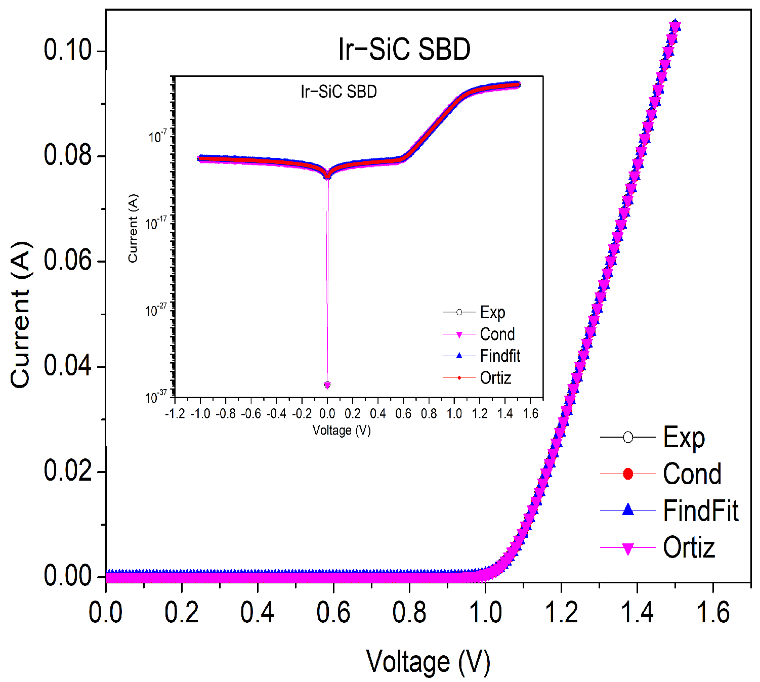
Figure 1. Experimental data and numerical characteristics obtained via the three methods for the Ir-SiC-based SBD. The inset figure shows the semi-log scale for these characteristics.
Energies 15 01667 g001
Figure 2. Experimental data and numerical characteristics obtained via the three methods for the Au-GaAs-based SBD. The inset figure shows the semi-log scale for these characteristics.
Energies 15 01667 g002
Figure 3. Deviation between experimental data and numerical characteristics obtained via Ortiz–Condé method for the Ir-SiC-based SBD.
Energies 15 01667 g003
Figure 4. Deviation between experimental data and numerical characteristics obtained via the Findfit method for the Au-GaAs-based SBD.
Energies 15 01667 g004
Figure 5. Experimental data and numerical characteristics obtained with the three methods for the organic-based SBD. The inset figure shows the semi-log scale for these characteristics.
Energies 15 01667 g005
Figure 6. Deviation between experimental data and numerical characteristics obtained with the Findfit method for the organic-based SBD.
Energies 15 01667 g006
Table 1. Iridium-silicon carbide Schottky diode physical parameters values obtained via three different methods using the experimental I-V characteristics.
ConductanceIntegralFindFit
I s ( 10 20 A) 1.9 1.9 1.9
η 1.02 1.02 1.02
R s ( Ω ) 3.48 3.48 3.48
R s h ( 10 9 Ω ) 3.10 3.11 3.11
Table 2. Gold-gallium arsenide SBD physical parameters extracted by three different methods based on the experimental I-V characteristics.
ConductanceIntegralFindFit
I s ( 10 17 A) 4.1 4.1 4.1
η 1.05 1.05 1.05
R s ( Ω ) 718718719
R s h ( 10 10 Ω ) 2.2 2.2 2.2
Table 3. Organic Schottky diode physical parameters values obtained via three different methods using the experimental current–voltage data.
ConductanceIntegralFindFit
I s ( 10 8 A) 3.6 88
η 5.08 5.05 5.05
R s ( Ω ) 919191
R s h ( k Ω ) 16.315 16.315 16.315
Publisher’s Note: MDPI stays neutral with regard to jurisdictional claims in published maps and institutional affiliations.