1. Introduction
Power companies, pursuing a technical policy related to ensuring the efficient operation of equipment [
1] in the context of digital transformation of the energy sector [
2,
3], impose ever higher demands on the reliability of power transformers [
4]. Currently, transformers must have a service life of at least 30 years and a warranty period of at least 5 years from the date of commissioning, and they should not need to have an overhaul and to have additional pressing of their windings during the entire service life [
5].
To ensure the reliability and extend the service life of power transformers [
6], both new and those a long-time in operation, it is important to elucidate the effect of a set of influencing factors. The findings of the analysis of data on accidents in power transformers attest to the fact that one of the main causes of failures is the reduction in the dielectric strength of transformer oil during operation [
7], which is both the internal insulation and the cooling medium [
8,
9]. Quite often failures lead to the ignition of transformer oil, subsequent fire, and explosion [
10,
11]. To meet the growing need for the reliability of energy systems, work is performed to create and adopt new transformers with improved characteristics in the energy industry [
12,
13].
The CIGRÉ report [
14] analyzes the reliability of about 50,000 power transformers of different capacities and voltage classes over a long period of operation in power systems abroad. The results of these studies show that for transformers with a service life of up to 20 years, the average failure rate corresponds to 0.02 per 1/year. In European countries, the failure rate was at 0.05 per 1/year, and in Australia and New Zealand, it was 0.01 per 1/year. At the same time, about 40% of failures led to the need for emergency and restoration overhaul of transformers.
According to the data presented in [
15], in Russia, the most frequent transformer accidents are caused by internal short circuits in the insulation, in high-voltage bushings, and on-load tap changing devices. More than 250 accidents have been reported because of damage to these functional units.
It should be noted that the use of modern transformer differential protection terminals that are based on artificial intelligence systems for external short circuits enables significant reduction in the protection tripping time to a 0.5 period, which notably reduces the consequences of damage [
16,
17]. However, the damageability of transformers due to a breakdown of the dielectric strength of the insulation is still high.
Assessment of the dielectric strength of the insulation and the development of timely technical intervention measures will allow the transition to the operation of transformers based on the risk of failure [
18], taking into account the inspection-based condition ranking [
19,
20].
2. Literature Review and Problem Statement
As the rated voltage of power transformers increases, so do the requirements for oil insulation reliability. This is confirmed by the fact that the regulatory document [
21,
22,
23] presupposes determination of the average breakdown voltage of transformer oil as a diagnostic parameter that characterizes the technical condition of oil insulation while taking into account the rated voltage class of the equipment (
Table 1). According to the regulatory documents [
21,
22,
23], breakdown voltage is determined in a standard arrester.
At the same time, regulatory documents [
21,
22,
23] do not define the effect of power transformers’ rated capacity on the dielectric strength of oil insulation. Increasing the capacity of the transformer at a given rated voltage entails an increase in the diameter of the core rod, which leads to an increase in the size of the electrical insulation structure inside the transformer tank and the transformer as a whole.
Transformers with the same rated capacity can have different rated voltage classes. This indicates that transformers with the same rated voltage but different capacity, and vice versa, have significant differences in overall dimensions. Increasing the overall dimensions of insulating structures increases the cost of power transformers, in which the cost of insulating structures, including transformer oil, accounts for 15–20% of the cost of the entire transformer.
An increase in the overall dimensions of the transformer with increasing its capacity is accompanied by an increase in the volume of transformer oil in the tank [
24]. As the volume of oil increases, the dielectric strength of the oil insulation decreases [
25], which is due to the probabilistic nature of breakdown formation in oil [
26]. With the oil volume rising, the probability increases that an element with low dielectric strength appears, which leads to a decrease in the strength of oil of a given volume [
27]. This indicates that the oil volume acts as a generalized influencing factor, which, when it rises, reduces dielectric strength. The most substantial percentage decrease in oil strength is noted for oils containing an increased quantity of impurities. The presence of impurity particles determines the statistical nature of the oil breakdown formation [
28]. Consequently, the decrease in breakdown strength with an increase in the oil volume is determined by the statistical patterns of the oil breakdown development.
This also fully applies to the major insulation of power transformers.
The major insulation of power transformers is the oil insulation between the following: the windings and the core; the windings of one rod of the core over the entire height of the windings; the windings of adjacent rods of the core (between the phases); the windings and the tank wall. In the practices adopted in this country, the major insulation is of the oil-barrier type, consisting of alternating oil passages and pressboard barriers.
Experimental studies show [
29,
30] that when AC and pulse voltages are applied to the major insulation, the highest values of electric field strength take place in the oil passage between the high-voltage winding and the barrier [
31], where partial discharges with an intensity of 10
−7 to 10
−6 C and more occur. This passage is called the first oil passage [
32,
33]. Its breakdown produces irreversible damage to the pressboard, which, depending on the intensity of the partial discharges, leads to a discharge along the surface of the pressboard or inside it, and a complete breakdown of the insulation is possible later on. During the operation and testing of the equipment, the occurrence of such damage is unacceptable. Therefore, the dielectric strength of the oil-barrier insulation is determined by the strength of the first oil passage.
Methods for choosing the major insulation of transformers are currently based on the results of experimental determination of the breakdown strength of transformer oil on models [
34]. Studies of the dielectric strength of oil-barrier insulation are carried out for different widths of the oil passage, which is typical of real power transformers [
32,
33]. To compare the allowable strengths obtained on models of oil-barrier insulation of transformers with the calculated values, the current methods use the relationships between the minimum breakdown strength and the width of the oil passage adjacent to the HV winding under various electrical influences. The dependence of the breakdown strength of the oil passage on its width is determined using empirical formulas.
Studies of the dielectric strength of transformer oil, however, as mentioned above, made it possible to establish that the breakdown strength value depends not only on the width of the oil channel, but also on the area of the electrodes. At the same time, the existing methods for choosing the major insulation of transformers take into account the influencing factors only by indirectly introducing a constant correction factor.
Thus, improving the existing techniques and creating new techniques for assessing the condition and analyzing the major insulation of power transformers is currently an urgent task.
In accordance with the established specifications of the methods for electrical testing of electrical insulating liquid materials [
21,
22,
23], it is assumed that to assess the condition of the transformer oil one should determine the statistical coefficient of variation, which characterizes the variation in breakdown voltage
where
σu is the root mean square error of the arithmetic mean of the breakdown voltage (standard deviation);
is the arithmetic mean of the breakdown voltage.
According to the standard [
21], the limit value of the coefficient of variation is 20%, which is significantly higher than the values for commercially pure mineral oils, which reach values of 10–15%. The breakdown mechanism of transformer oil is statistical in nature, and if the coefficient of variation exceeds these statistical values, it indicates a decrease in the quality of transformer oil, and thus a deterioration in its technical condition.
According to [
23], the coefficient of variation is in the range of 9% to 37% at a confidence level of 95%, which means that there can be even more scattered values.
Thus, the use of the standardized value of the variation coefficient, which has no scientific backing to it, means to loosen significantly the requirements for the quality of transformer oil in operation, which leads to an increase in the probability of insulation breakdown.
The coefficient of variation is a statistical parameter of the breakdown voltage. With an increased spread of transformer oil breakdown voltages, the probability of the breakdown [
35] of oil passages in the insulation of transformers at lower values of the applied voltage increases, which leads to a decrease in the technical condition and operational reliability of transformers.
The standard test [
36] provides a method for determining the value of the difference between the maximum
Umax and minimum
Umin breakdown voltage for each oil sample taken, multiplied by three, as a statistical characteristic of the dielectric strength of oil. The result thus obtained should be less than the minimum breakdown voltage.
The above standards set different values of statistical standardized parameters of the dielectric strength of oil, and they also fail to reflect the specific aspects of the effect on the dielectric strength of oil passages of rated capacity and specific features of the design of power transformers.
It should also be noted that, at present, little attention is paid in the scientific and engineering literature to the analysis of the results of statistical characteristics of the breakdown voltage of transformer oils in the standard surge arrester, which makes it difficult to select and develop more reasonable diagnostic statistical characteristics of the dielectric strength of oil for power transformers, taking into account both their capacity and voltage class.
Thus, based on the above, it is necessary to investigate and establish the main statistical characteristics of the dielectric strength of transformer oil in the major insulation passages for a wide range of rated technical parameters of power transformers. For this purpose, building upon the existing design experience, it is required to develop a technique for evaluating statistical characteristics and select such diagnostic parameters for them, which would ensure the required level of dielectric strength of the major insulation during operation.
3. Determination of the Statistical Characteristics of the Dielectric Strength of Oil with Regard to Its Volume Using the Three-Parameter Gnedenko–Weibull Distribution
On the basis of test results and operating experience, it was found that the statistical characteristics of oil breakdown voltages are the parameters of the normal distribution of a random variable. However, as the oil volume in the transformer increases, the integral dependency shifts to the region of negative breakdown voltage values, which contradicts the physical meaning of this process.
In [
35,
36], the third limit law of the distribution of the extreme members of the sample, which has restrictions on the left, the lower limit of the breakdown voltage, is successfully applied when recalculating breakdown voltages from small samples to large ones. This is due to the fact that the breakdown occurs in the weakest point of the oil insulation, where more favorable conditions are formed for its development [
37]. Consequently, the breakdown voltages reflect the distribution of the extreme members of the sample [
38]. All this points to the fact that the physical meaning of the breakdown formation in transformer oil corresponds to the third limit law of the distribution of the extreme sample members. In applied works, including when determining the dielectric strength of transformer oil, this distribution is known as the Gnedenko–Weibull distribution [
39,
40].
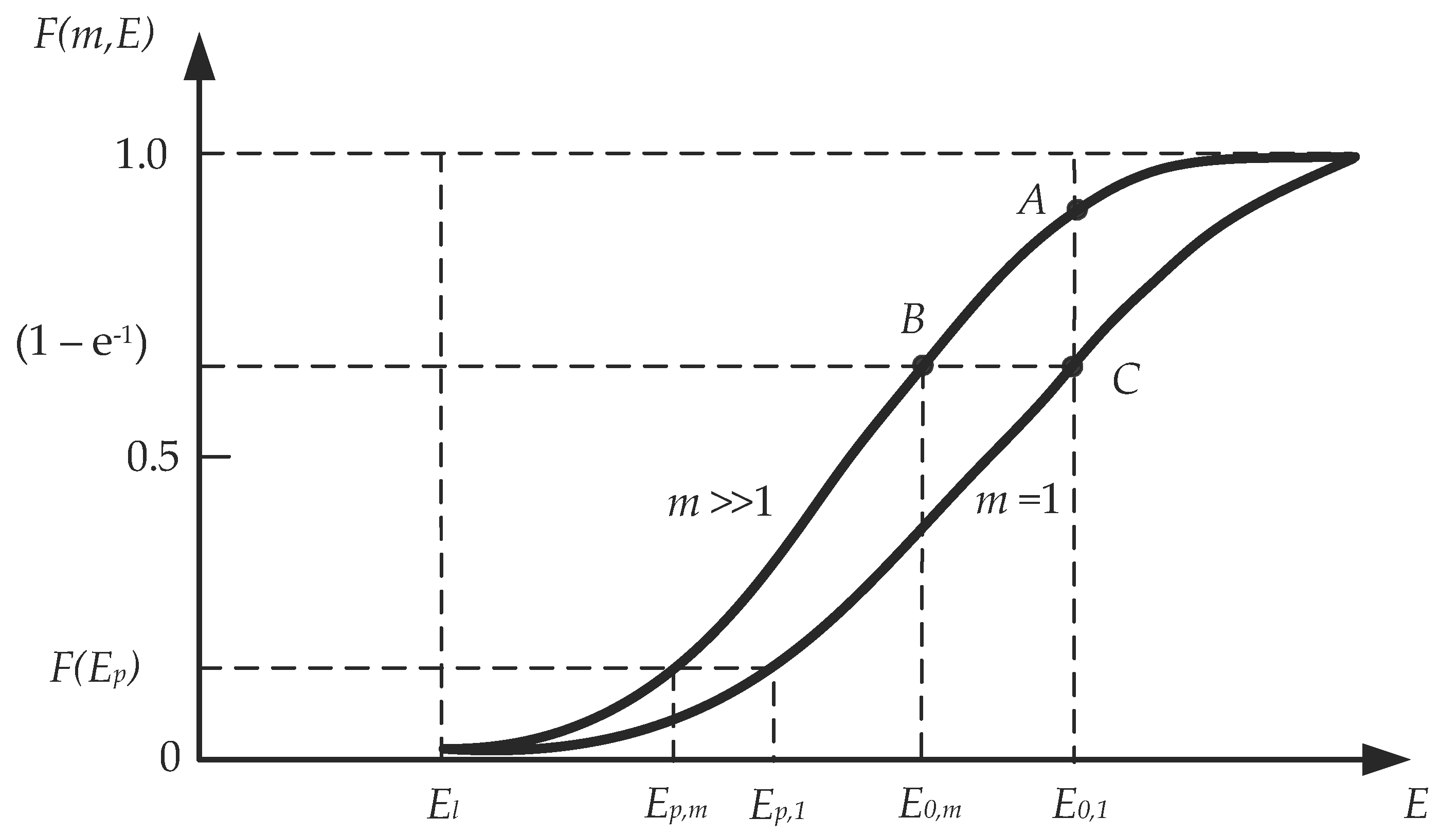
In studies dedicated to the determination of the statistical characteristics of dielectric strength using the three-parameter Gnedenko–Weibull distribution, the model of a large volume of transformer oil is considered in the form of m identical elementary (unit) volumes of oil connected in parallel.
Figure 1 shows the form of the breakdown voltage distribution function for a unit volume
m = 1 and for an arbitrary volume
m >> 1 of transformer oil.
The dependency of the oil breakdown probability on the number of m elementary (unit) oil volumes connected in parallel according to the Gnedenko–Weibull distribution is of the form
where
E0,1 is the value of the breakdown voltage of a single oil passage, at which
F(
E0,1) = 1 − e
−1;
El is the lower limit of the breakdown voltage; α is the dimensionless Gnedenko–Weibull distribution parameter.
For an arbitrary oil volume
m >> 1, the oil breakdown probability function (breakdown voltage distribution function) is written as
where
E0,m is the breakdown voltage of the oil passage, at which
F(
E0,m) = 1 − e
−1;
αm is a dimensionless parameter for a given number m of elementary (unit) oil volumes.
The shift of the oil breakdown voltage distribution function to the lower values region with increasing volume (
m >> 1) is due to the statistical nature of breakdown formation (
Figure 1). As the oil volume increases, the amount of impurities involved in the formation of breakdown conditions increases, which worsens the condition of the oil. Therefore, the probability of a breakdown increases. It should be noted that the quality is the same for the same oil, so the lower limit of the breakdown voltage of transformer oil E
l for physical reasons remains the same. Then, the statistical characteristics of the dielectric strength of oil
E0,m and
αm when the volume changes are determined from expressions (2) and (3), which coincide with each other for physical reasons. In this case, the expressions are identical when
αm =
α. Comparing the right-hand sides of expressions (2) and (3) at
E =
E0,1 we obtain
Thus, if we change the oil volume (parameter m) in the transformer, the distribution of the breakdown voltage of the transformer oil of a given quality, which has the form of the Gnedenko–Weibull distribution, it is only the parameter of the oil passage breakdown voltage value E0,m that changes, and the other two parameters (El and α) in expression (4) remain unchanged.
Then, the expression for the breakdown voltage distribution function for an arbitrary oil volume is of the form
From expression (4) the parameter
E0,m is expressed, which will take the form
The obtained expression (6), in contrast to the existing techniques of calculating the electrical insulation strength, reflects the physical meaning of the effect of the transformer oil volume and its condition in terms of quality parameters with respect to the breakdown voltage and allows one to estimate the lower limit of the breakdown voltage of transformer oil.
When calculating the dielectric strength of oil passages in power transformers, it is important to know the change in breakdown voltage
Ep at a given breakdown probability
Pspec as a function of the volume of oil. As a result of the transformations, expression (6) for determining the breakdown voltage
E0,
m will take the following form
where
Pspec is the specified probability of oil breakdown, which is taken as 0.05 for insulation calculations.
4. Technique for Calculation of Statistical Characteristics of the Dielectric Strength of Oil in the First Passage of the Major Insulation of a Transformer
The major insulation between the transformer windings of the higher and lower voltages is assessed using the expression
where
Udesign is the design voltage acting on the major insulation;
kins = 1.1–1.2-a factor of the increase in electric field strength in the oil passage due to the presence of barriers and cylindrical design of the major insulation;
Eop.bd.min is the minimum breakdown voltage as determined at a given breakdown probability
Pspec;
kC.E is a correction factor that takes into account a small number of experiments used to obtain this dependency; smaller sizes of the model sample compared to the real-life transformer; possible deviations in the size of insulation elements.
According to expression (7), the minimum breakdown voltage of the oil at a given breakdown probability is
where
E0,1,
E0,m are the values of the breakdown voltage of a single oil passage and that increased m
d times, at which the probabilities of breakdown are equal to the following:
F(
E0,1) =
F(
E0,m) = 1 − e
−1; E
l is the lower limit of the breakdown voltage of the oil passage;
α is the dimensionless parameter of the Gnedenko–Weibull distribution.
The increase in the volume of oil in transformer passages as compared to a single (initial) passage is shown by the parameter mk.
Taking into account (9), expression (8) will take the form
The volume of the first oil passage for the rated values of voltage and power of transformers, given statistical characteristics, is determined by the expression
where
is the rated power of the transformer,
is the reactive component of the short circuit voltage (p.u.),
is the first oil passage between the high-voltage winding and the first barrier,
is the thickness of the insulation of the LV winding from the rod, which is selected according to the test voltage of the transformer insulation.
The increase in the volume of oil in the passages of transformers as compared with a single (initial) passage is shown by the parameter
mk, which is defined as
where
Vop,B is the volume of the oil passage of the basic model of the major insulation of the transformer (single insulation sample).
The basic model of the major transformer insulation is represented by a model that has been used to study the dielectric strength characteristics of transformer insulation by a number of countries, including Russia. Then, the volume of the oil passage of the basic model of the major insulation of the transformer per unit of its height will be determined by the expression
where
,
are the width of the oil passage and the radius of the high potential winding of the base model, respectively.
To determine the parameter
mk, taking into account formulas (11) and (13), the expression is written in the dimensionless form
Relative values of the parameters
E0,m/
E0,1 and
Eop.bd.min,m/
Eop.bd.min,1 in a dimensionless form
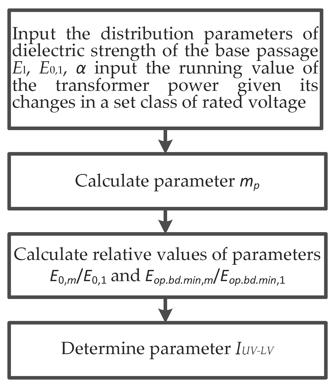
The studies and calculations performed by the authors are taken as a basis for the development of an algorithm for calculating the statistical characteristics of the dielectric strength of transformer oil in the first passage of the major insulation of transformers at different values of rated capacity. The calculation algorithm includes the following five steps.
The dielectric strength distribution parameters of the base passage El, E0,1, and the dimensionless distribution parameter α are set so as to take into account the coverage of different breakdown cases arising in operating conditions.
The current value of the transformer capacity is specified, taking into account the change in the given rated voltage class.
According to expression (14) the parameter of the oil volume in the transformer passages mk is calculated.
Using expressions (15) and (16), the relative values of the parameters E0,m/E0,1 and Eop.bd.min,m/Eop.bd.min,1 are calculated.
Expression (10) is used to determine the distances between the high and low voltage windings lHV-LV.
The block diagram of the developed algorithm is presented in
Figure 2.
5. Example of Selection and Calculation of Statistical Characteristics of the Dielectric Strength of the Oil in the First Passage of the Major Insulation of a Transformer
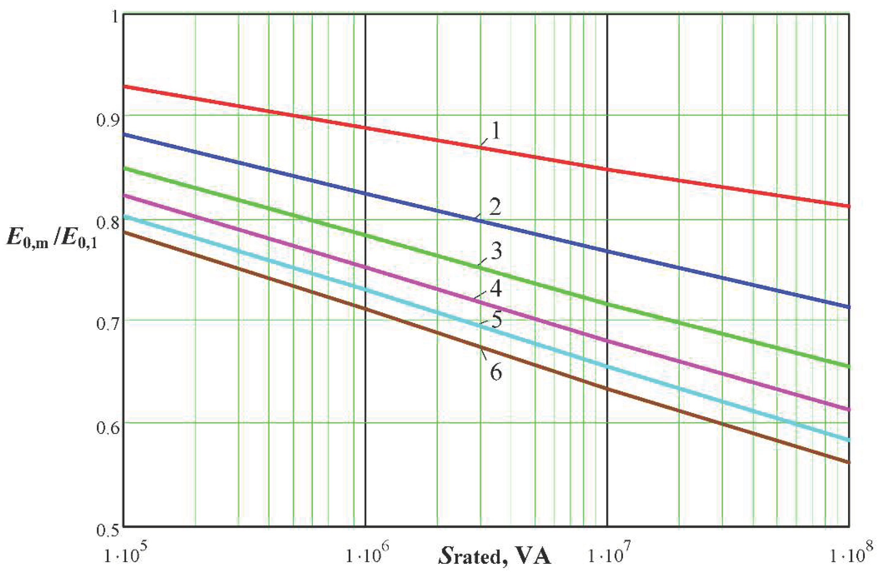
In line with the developed technique, the statistical characteristics of the dielectric strength of oil in the first oil passage were calculated for two-winding three-phase transformers with a voltage of 110 kV when changing their capacities in the range of 105 to 108 VA. Input data for such transformers have been adopted so as to take into account design and operating experience. The calculations were performed at different values of the parameters E0,1/El and α.
Calculation of the dielectric strength parameters showed the following. When the transformer capacity is increased from 10
5 to 10
8 VA, the dielectric strength of the first oil passage
E0,m/E0,1 decreases by 23%. For a given transformer capacity,
E0,1/El decreases as the
E0,m/E0,1 ratio increases (
Figure 3).
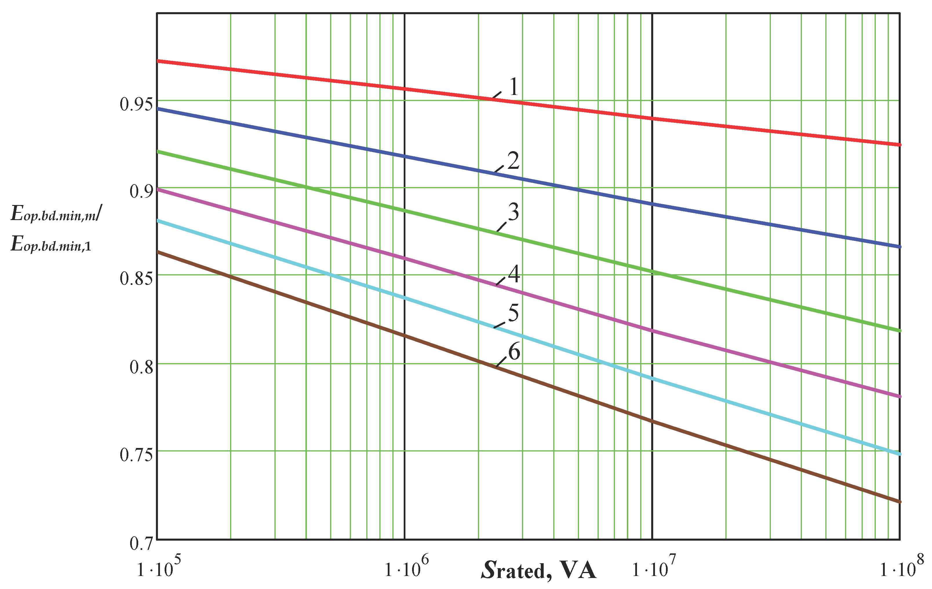
The dependency of
Eop.bd.min,m/
Eop.bd.min,1 with increasing transformer capacity leads to a decrease in the breakdown voltage in the investigated range
Sl by 16%. At the same time, there is a significant decrease in the
Eop.bd.min,m,m/
Eop.pr.min,1 with an increase in the ratio
E0,1/
El (
Figure 4).
Analysis of variation in the parameter α in the investigated range showed a noticeable (up to 5%) effect on the minimum dielectric strength of the oil, and there is a minimum of values of breakdown voltage
Eop.bd.min,m/
Eop.bd.min,1 when the parameter α takes value α = 2.5 (
Figure 5).
The relative values of the parameters E0,m/E0,1 and Eop.bd.min,m/Eop.bd. min,1 as dependent on the ratio E0,1/El for the parameter α = 2.5 showed that an increase in the ratio E0,1/El from 1.5 to 4 significantly decreases the values of the oil breakdown voltage (by 1.36 and 1.44 times for E0,m/E0,1, and by 1.17 and 1.28 times for Eop.bd.min,m/Eop.bd.min,1). To a greater extent, the breakdown voltage decreases with increasing transformer capacities.
When selecting oil passages for the major insulation of power transformers, it is important to determine such statistical parameters of oil breakdown voltage distribution, at which the dielectric strength of oil passages would not be less than the specified value for the initial capacity of the transformer at the corresponding rated voltage. The statistical parameters of the oil breakdown voltage distribution that meet this condition will be called reasonable statistical characteristics.
From the studies and calculations performed by the authors, it follows that the decisive main composite parameter is the ratio E0.1/El. The tendency of the ratio E0.1/El toward 1 shows that the scatter region of the breakdown voltage decreases. In turn, as the transformer capacity increases, the degree of reduction in the breakdown voltage of the oil decreases. The effect of the parameter α manifest itself to a lesser degree and its value is taken as 2.5, at which there is a minimum value of the breakdown voltage Eop.bd.min,m/Eop.bd.min,1 and in this case, the ratio E0.1/El will be higher than the specified value at all other parameters α.
Based on the calculations and the selected conditions,
Figure 6 shows the change in the ratio
E0,1/
El as a function of the transformer capacity for the parameter α = 2.5 at the given constant relative values of the minimum oil breakdown voltage
Eop.bd.min,m/Eop.bd.min,1: 0.85, 0.9, 0.95.
From the graphs of dependencies shown in
Figure 3, it follows that the values of the composite parameter
E0,1/
El for the original oil in the transformer model decreases with increasing transformer capacity, as well as with an increase in the allowable minimum breakdown voltage of oil
Eop.bd.min,m/
Eop.bd.min,1. Therefore, for transformers with higher capacities, the oil quality must be higher than the limit values and the following condition must be met
The obtained data for a given level of dielectric strength of the oil are reasonable statistical characteristics subject to the rated parameters of the transformer and the condition of its transformer oil.
6. Conclusions
The paper analyzes the effect on the dielectric strength of the major insulation of power transformers of different overall dimensions and oil volume as a function of rated parameters of capacity and voltage class.
A technique has been developed to calculate the statistical characteristics of the dielectric strength of oil in the first oil passage of the major insulation of transformers, taking into account the effect of capacity and voltage class of transformers, as well as statistical parameters of the breakdown voltage of the original transformer oil. Based on the proposed method, a sequential algorithm for calculating the statistical characteristics of dielectric strength and determining the distance between the windings of the highest and lowest voltage transformer has been developed. The calculation of statistical characteristics of the dielectric strength of oil using the three-parameter Gnedenko–Weibull distribution, which allows one to factor in the effect of the volume of oil for different transformers with a rated voltage of 110 kV when changing their capacity from 105 to 108 VA, has been performed.
Statistical characteristics of the dielectric strength of transformer oil using the three-parameter Gnedenko–Weibull distribution have been determined, allowing the effect of the oil volume to be taken into account.
The results of the calculations have shown that the greatest effect of 110 kV transformer capacity on the change in the statistical characteristics of the dielectric strength of the oil is associated with the condition in terms of quality parameters of the original transformer oil (ratio E0,1/El).
On this basis, relying on the technique proposed, the dependencies of the limit values of the ratio of dielectric strength of oil (E0.1/El)bd on the transformer capacity have been obtained at a value of the parameter α = 2.5 and given constant values of the relative minimum breakdown voltage of oil Eop.bd.min,m/Eop.bd.min,1: 0.85, 0.9, 0.95. It has been shown that these values should be applied when selecting the dielectric strength criterion of the major insulation of power transformers since for transformers of higher capacity, the oil quality should be higher and the relative values of the parameter E0.1/El should be lower.
Thus, the studies performed and the results obtained allow for calculating and assessing the condition of the major insulation of 110 kV transformers in terms of the statistical characteristics of the dielectric strength of oil.


