
A Summary Review on Experimental Studies for PCM Building Applications: Towards Advanced Modular Prototype

 ,
,
Abstract
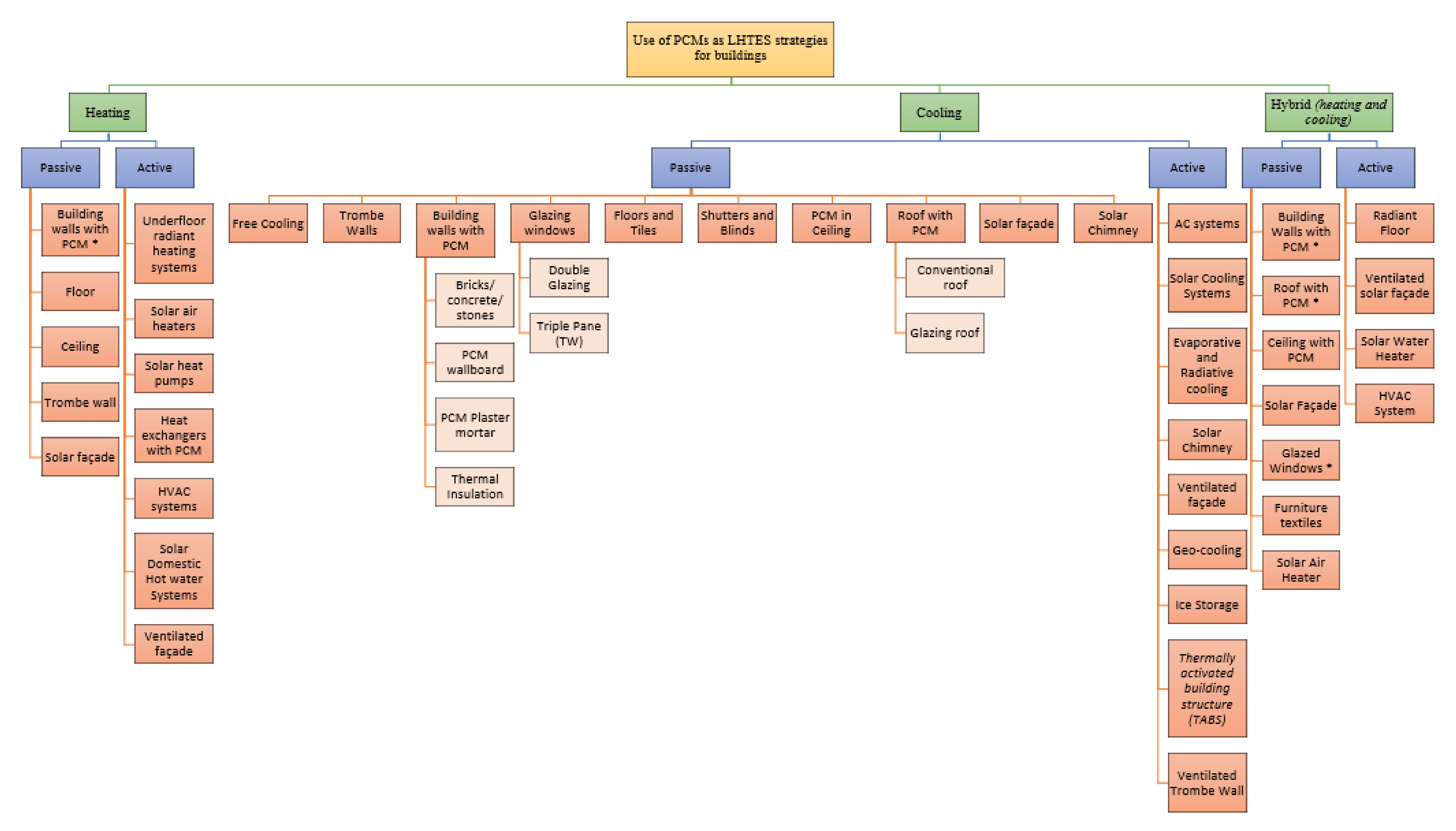
:1. Introduction
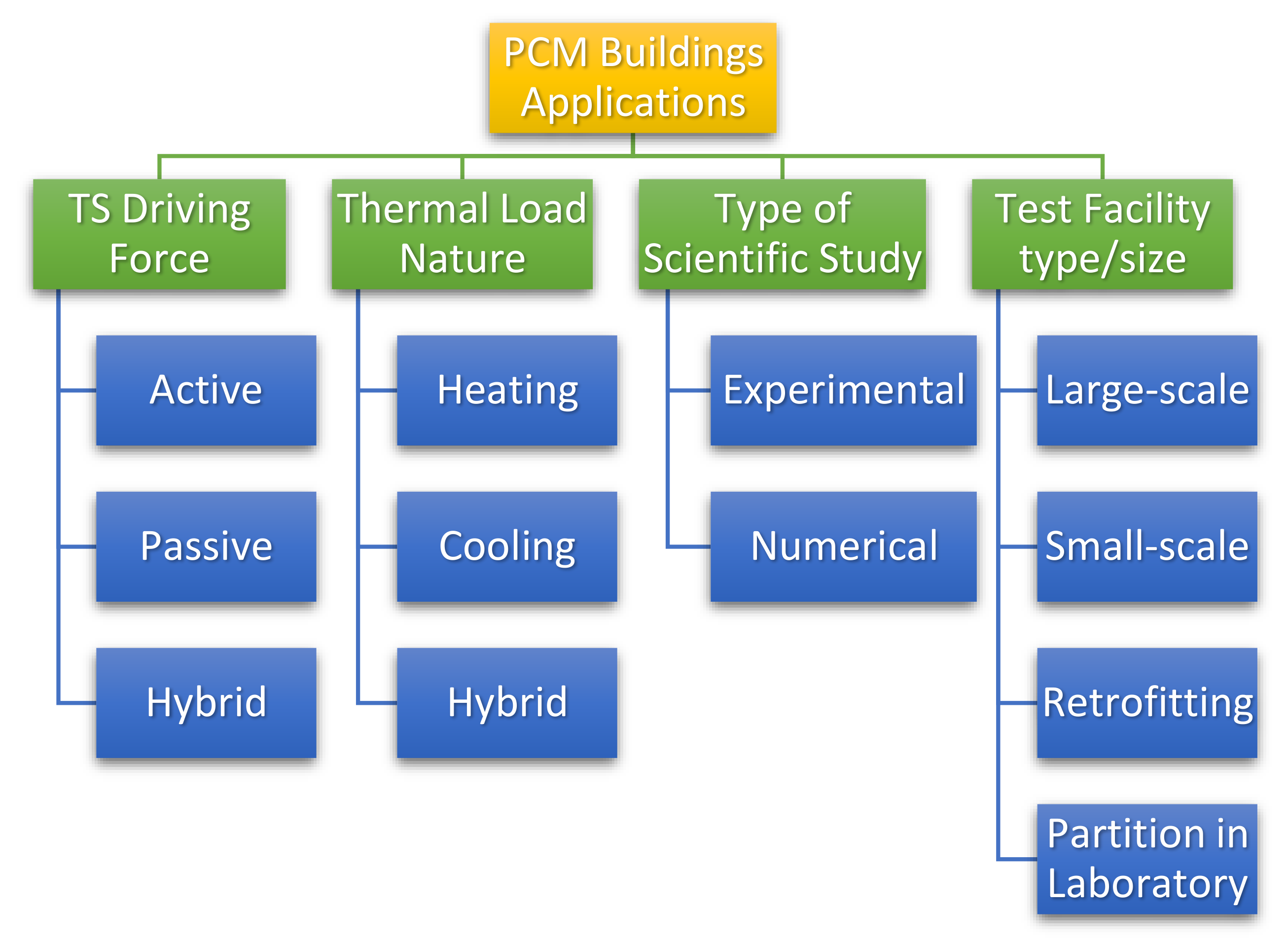
- Thermal storage driving force;
- Thermal load nature;
- Type of scientific study;
- Test facility type and size.
1.1. Summary of Recent PCM Building Application Reviews
1.2. Scope of the Current Study
2. PCM Experiment Classification Criteria and Methodology
3. Large-Scale Prototype PCM Experimental Studies
3.1. Active Large-Scale Applications
3.2. Passive Large-Scale Applications
4. Small-Scale Prototype PCM Experimental Studies
4.1. Active Small-Scale Applications
4.2. Passive Small-Scale Applications
5. Compartments Retrofitting PCM Experimental Studies
5.1. Active Retrofits Applications
5.2. Passive Retrofits Applications
6. Laboratory-Based PCM Building Partition Experimental Studies
6.1. Active Laboratory-Based Applications
6.2. Passive Laboratory-Based Applications
7. Discussion
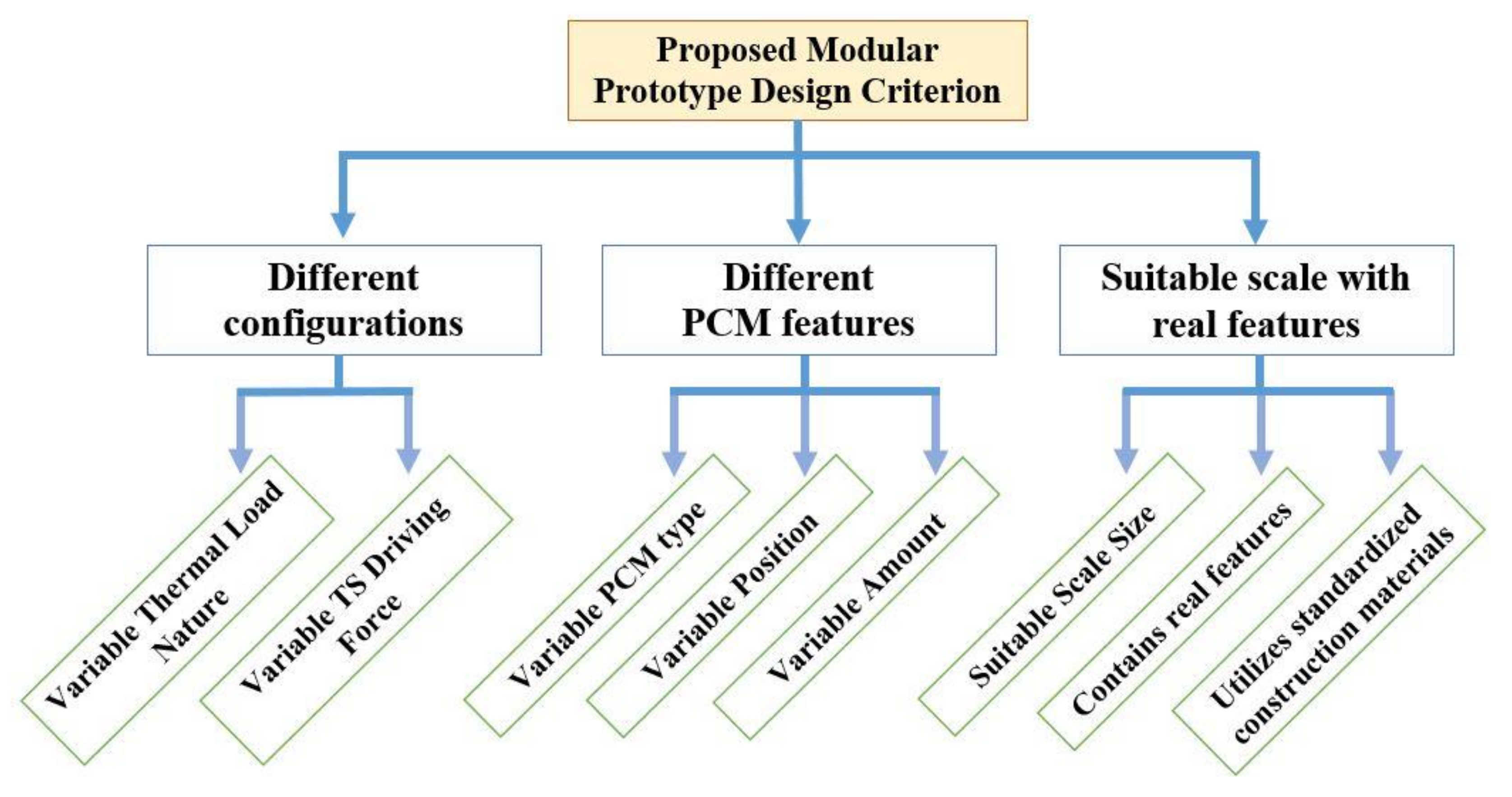
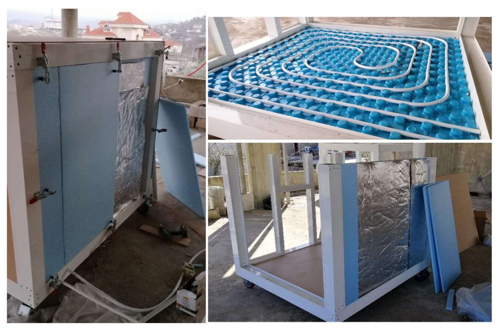
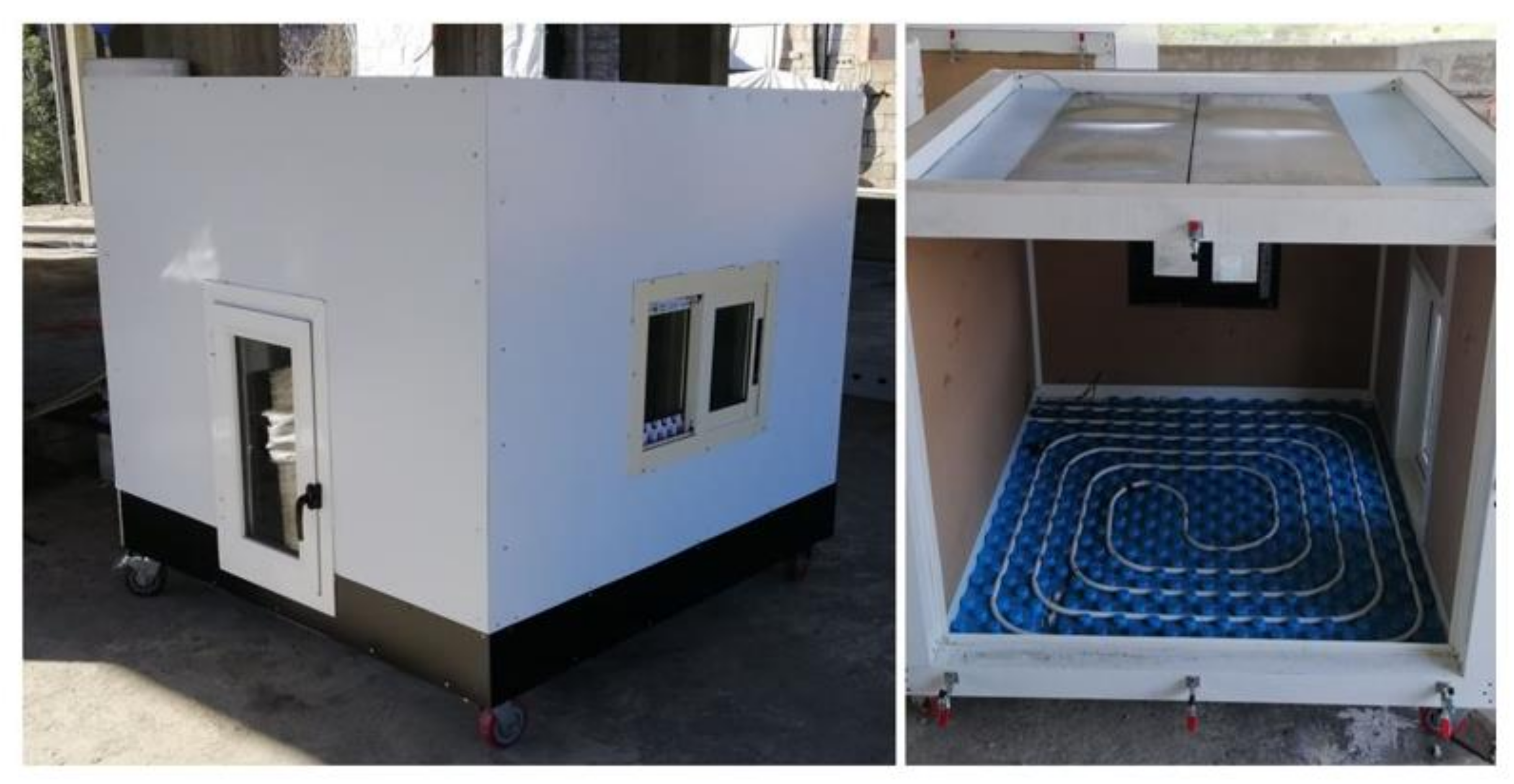
8. Proposed Design of the New Modular Prototype
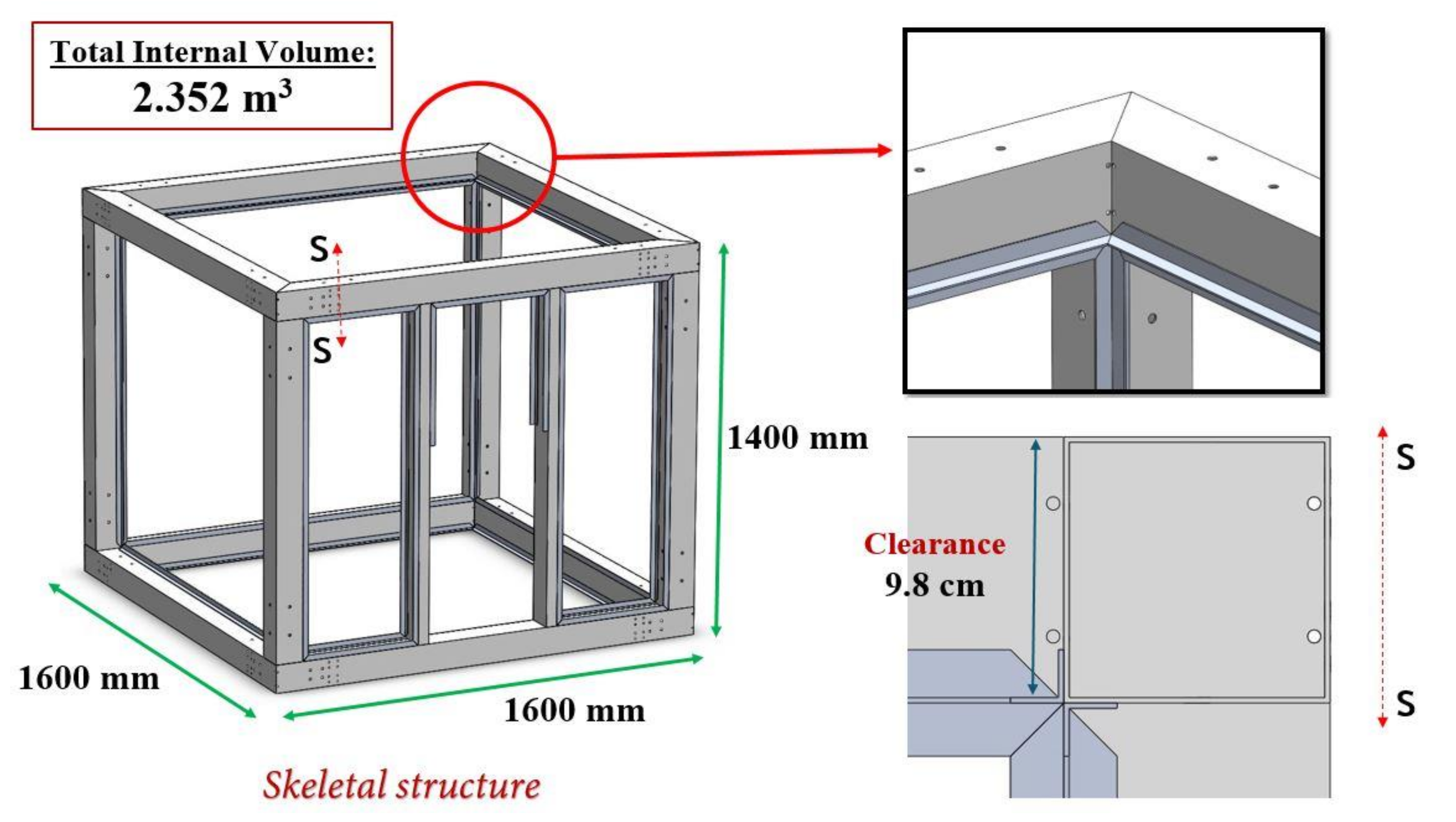
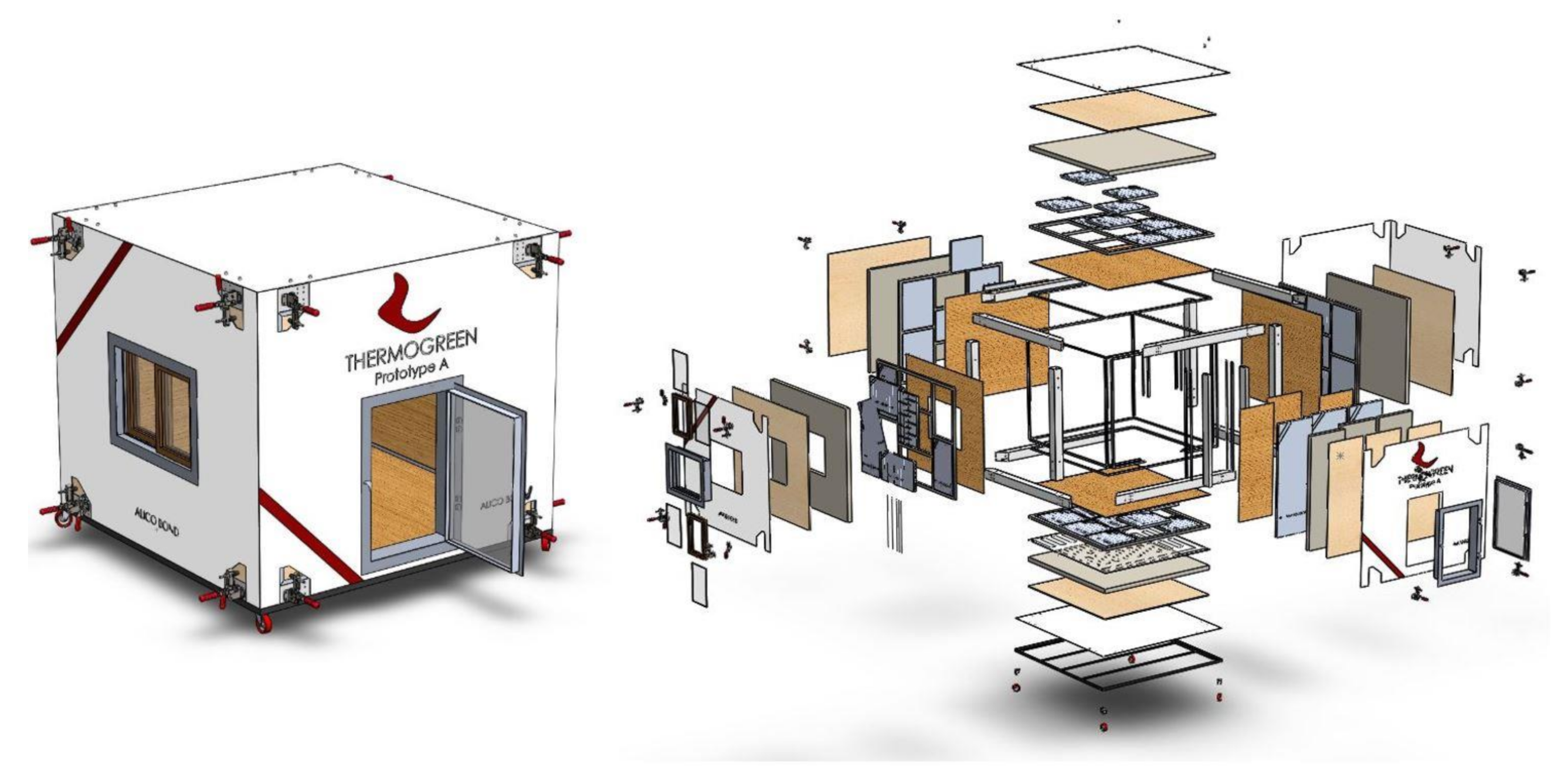
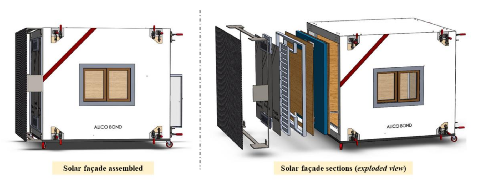
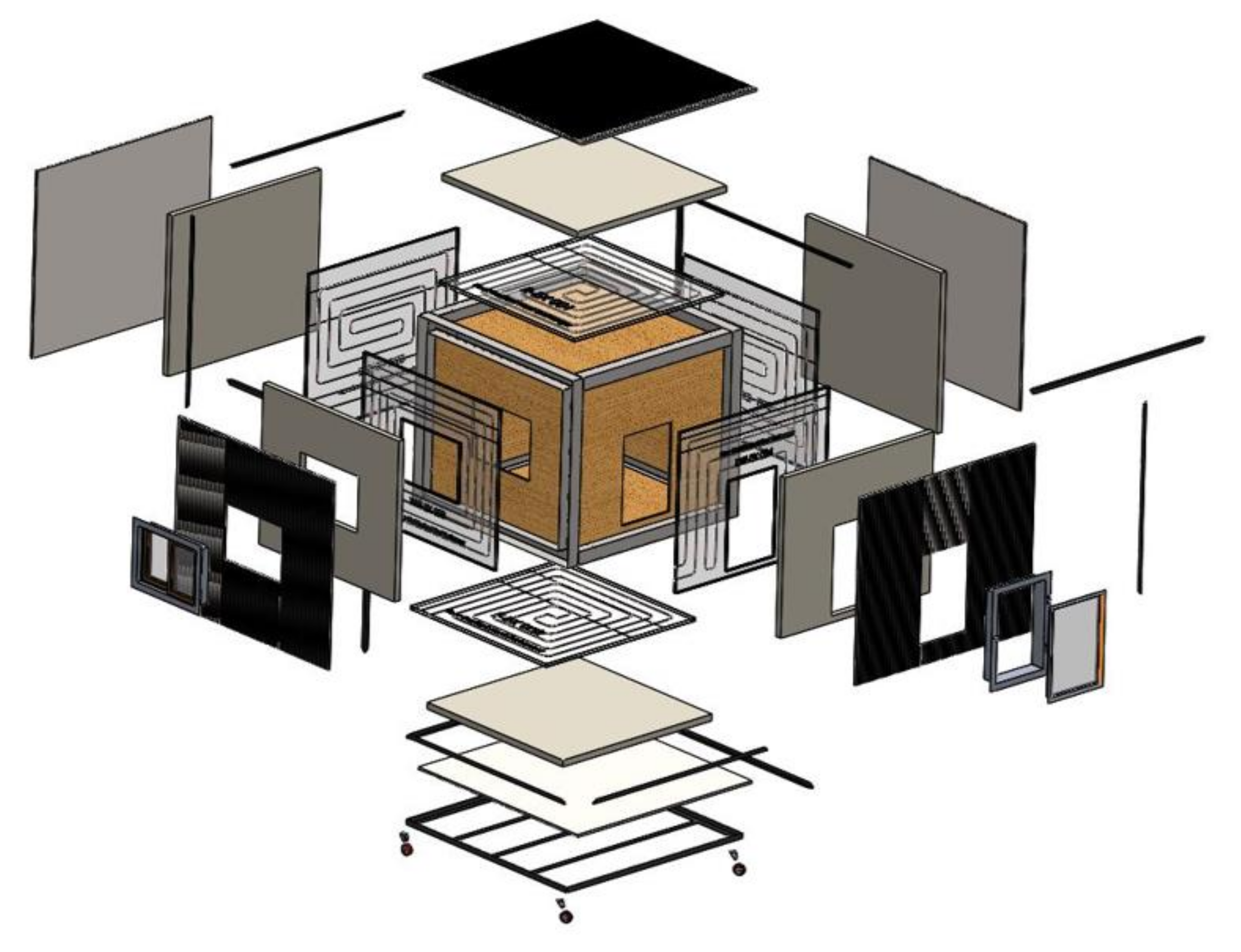
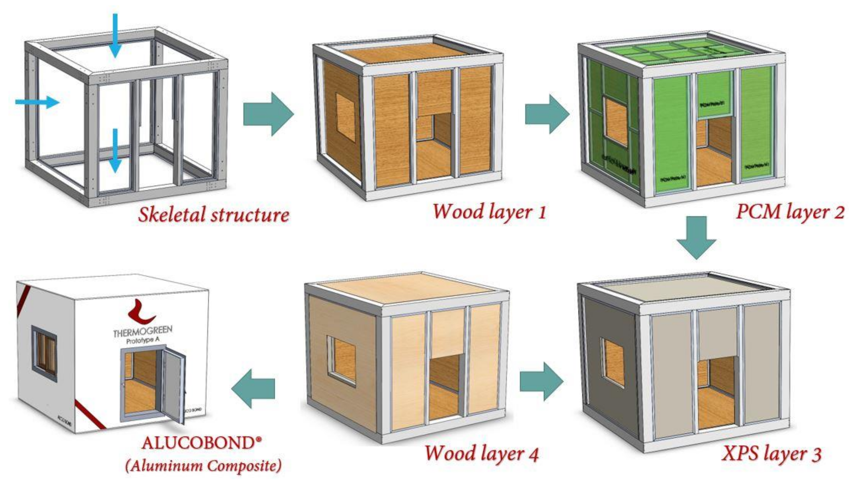
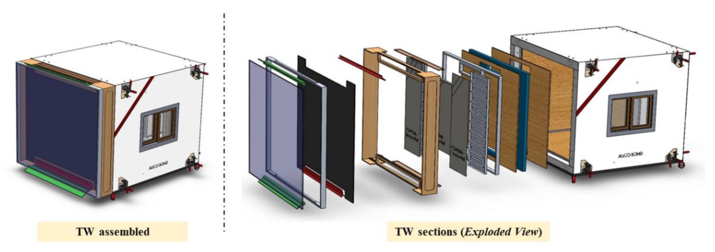
8.1. Structure and Dimensions
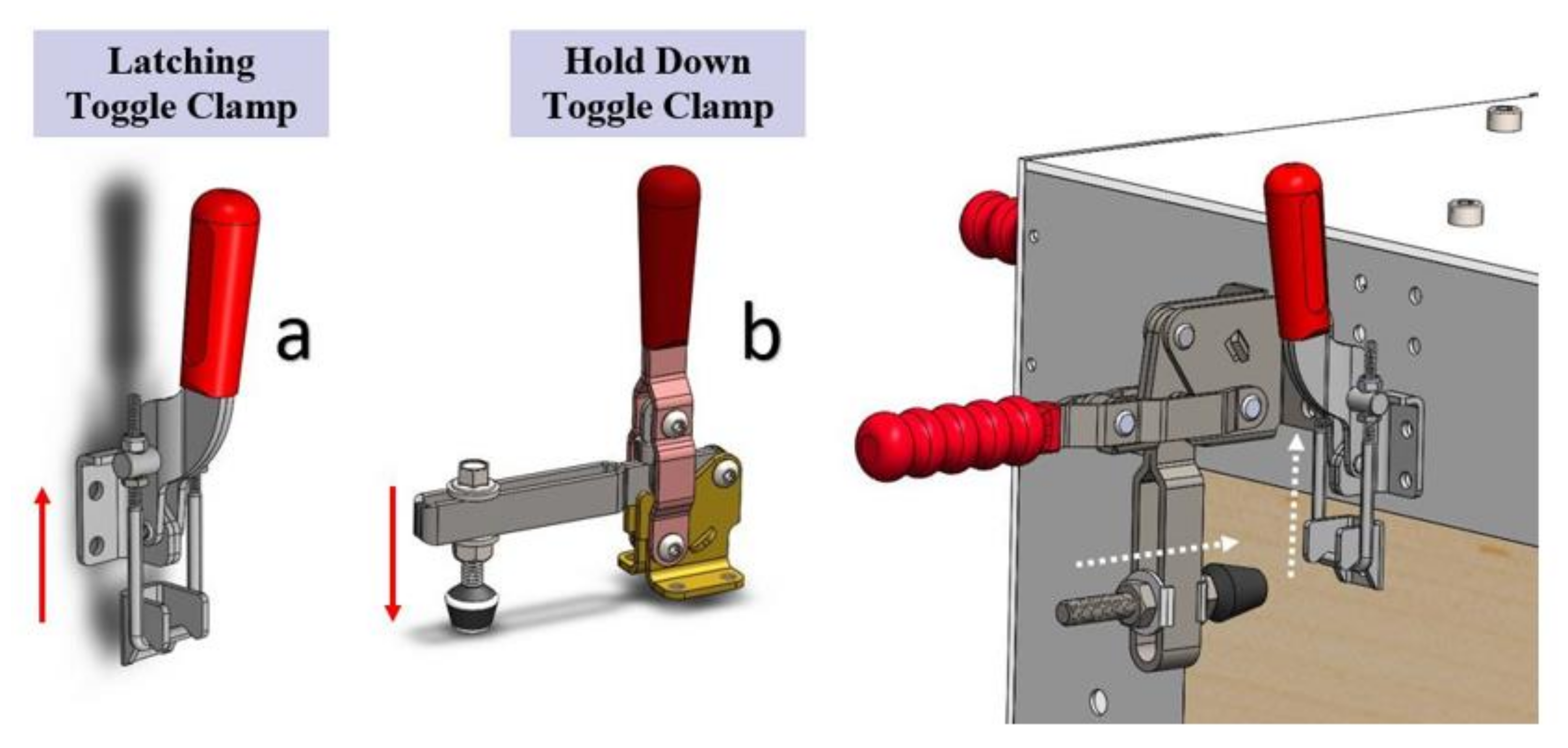
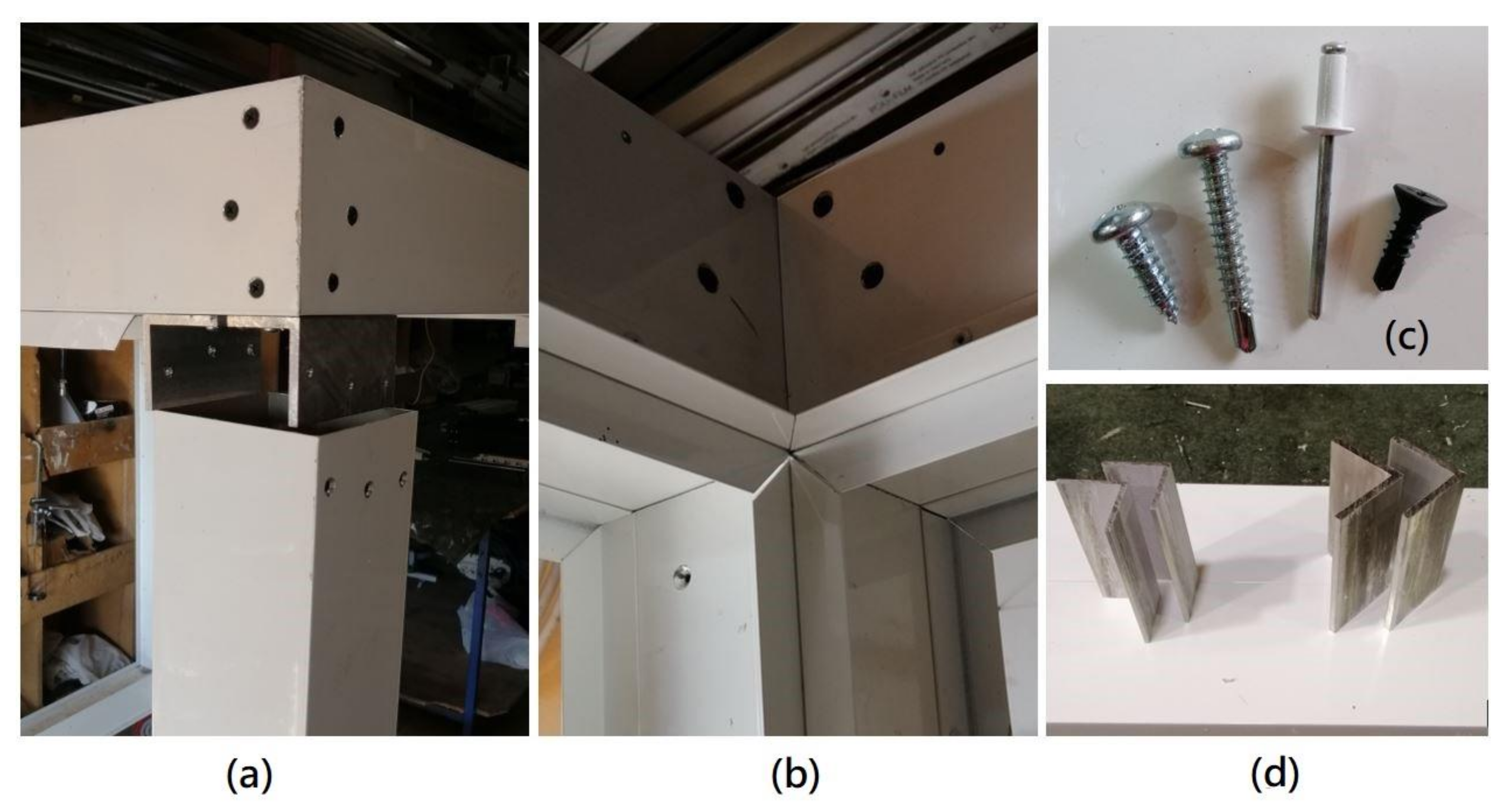
8.2. Method of Installation and Disassembly
- Vertical installation of all layers;
- Horizontal installation of sides and vertical installation of roof and floor.
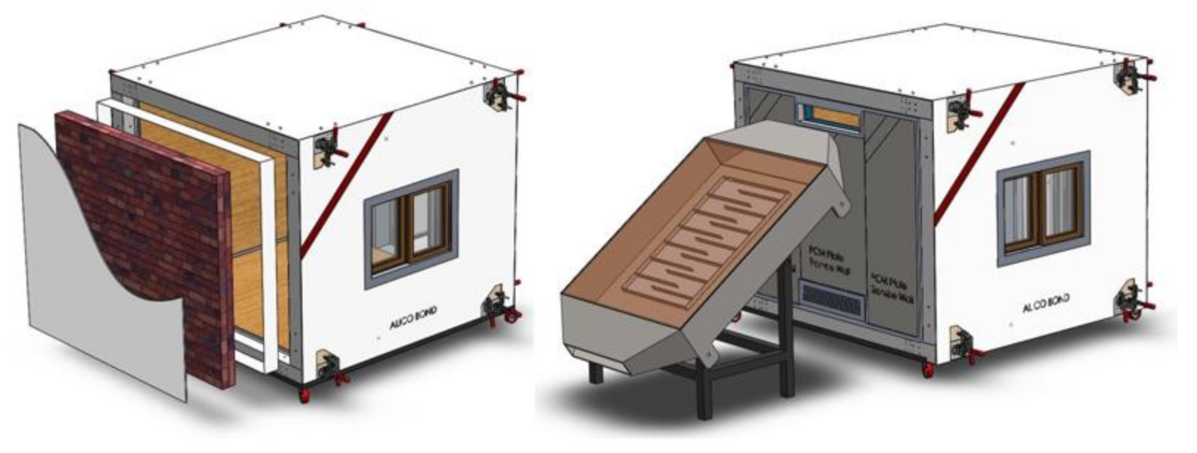
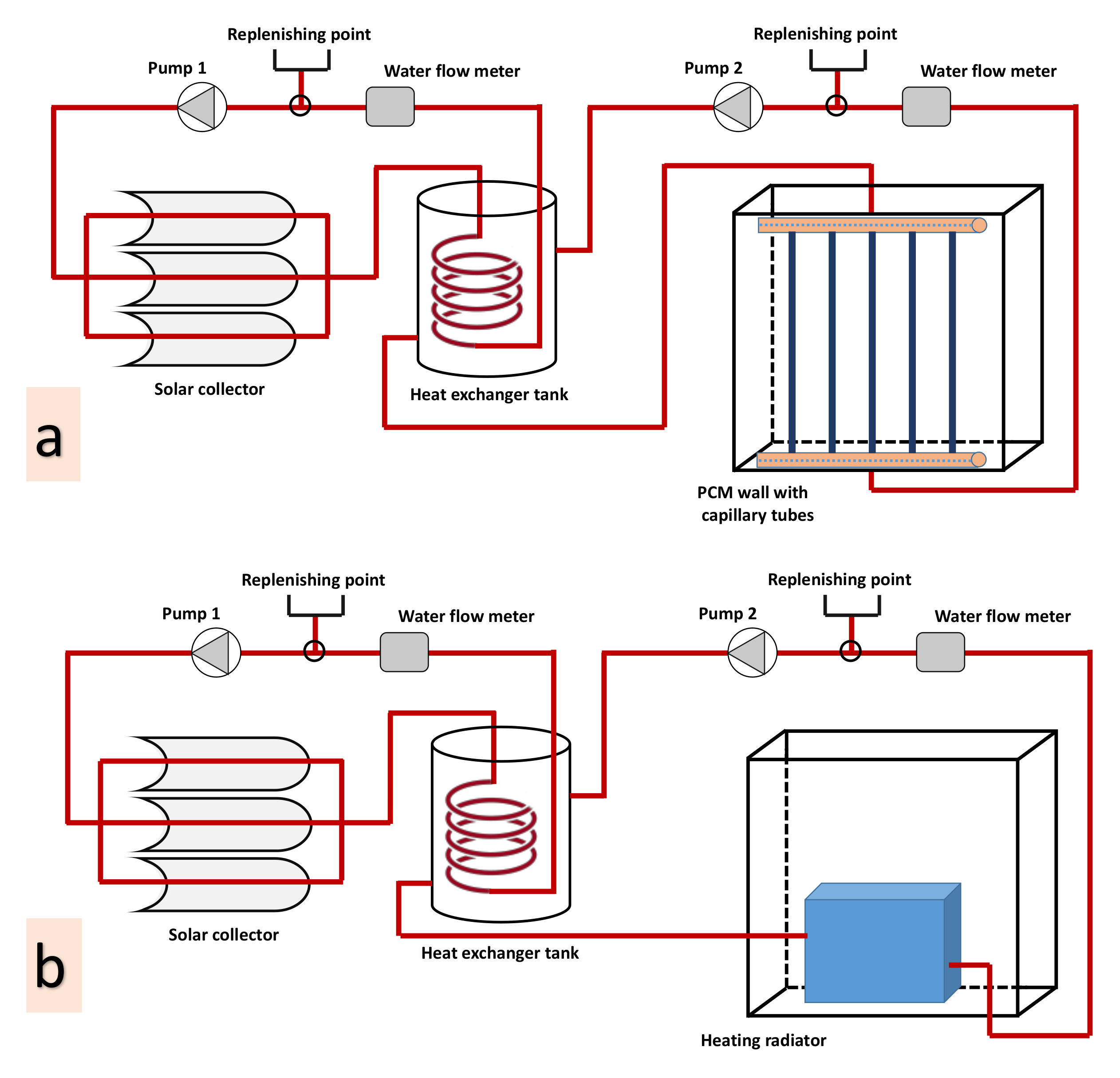
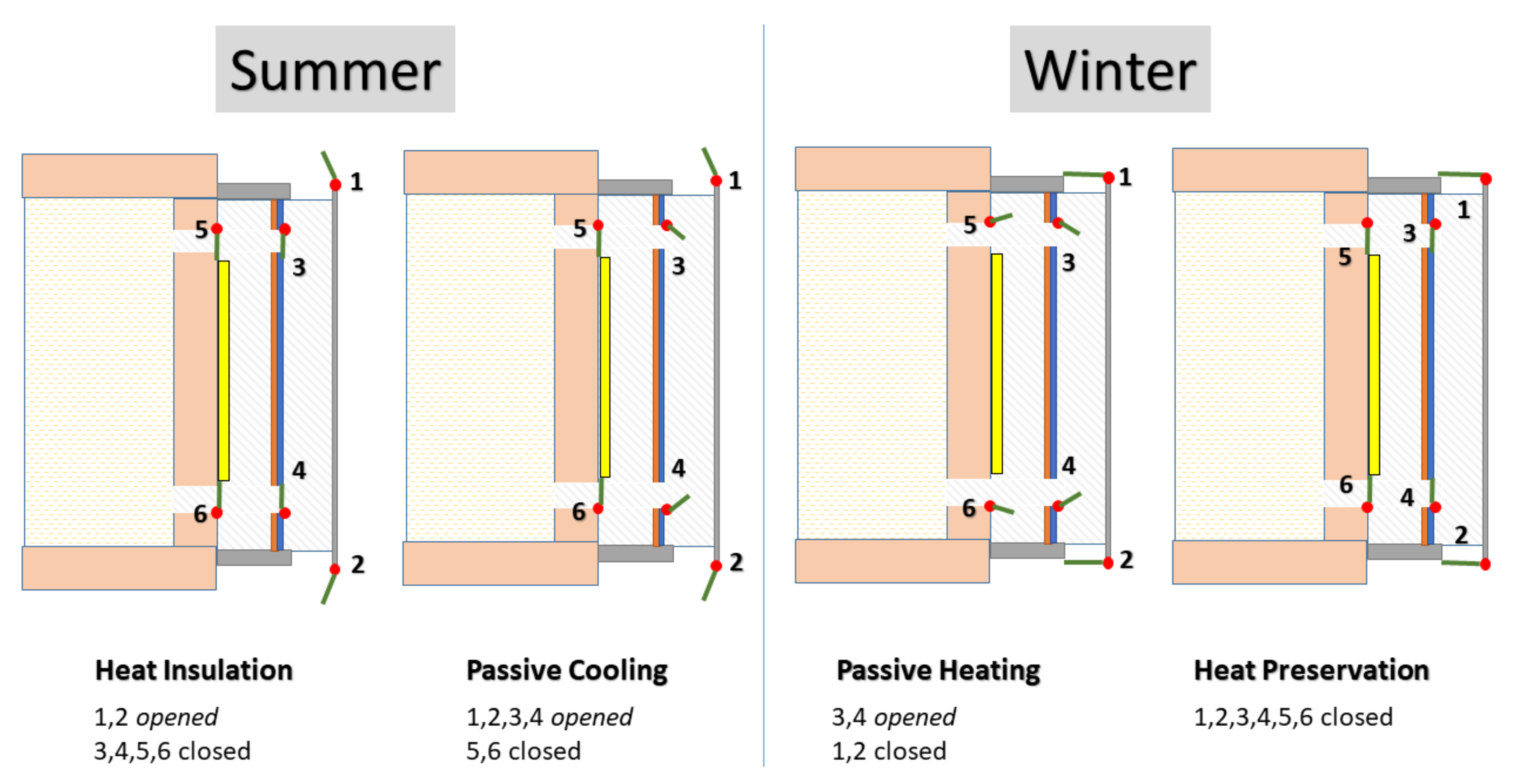
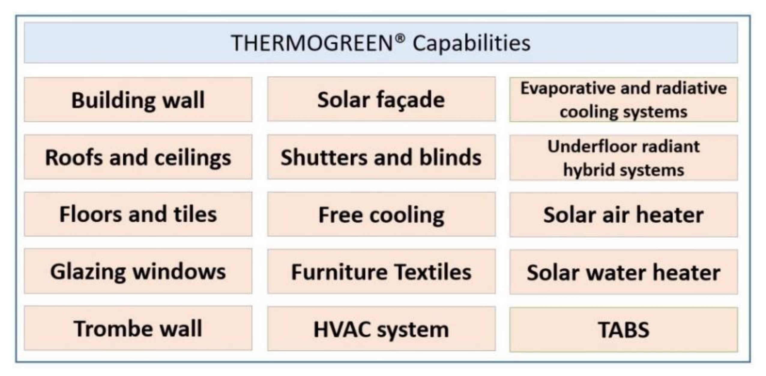
8.3. Capabilities and Possible Combinations
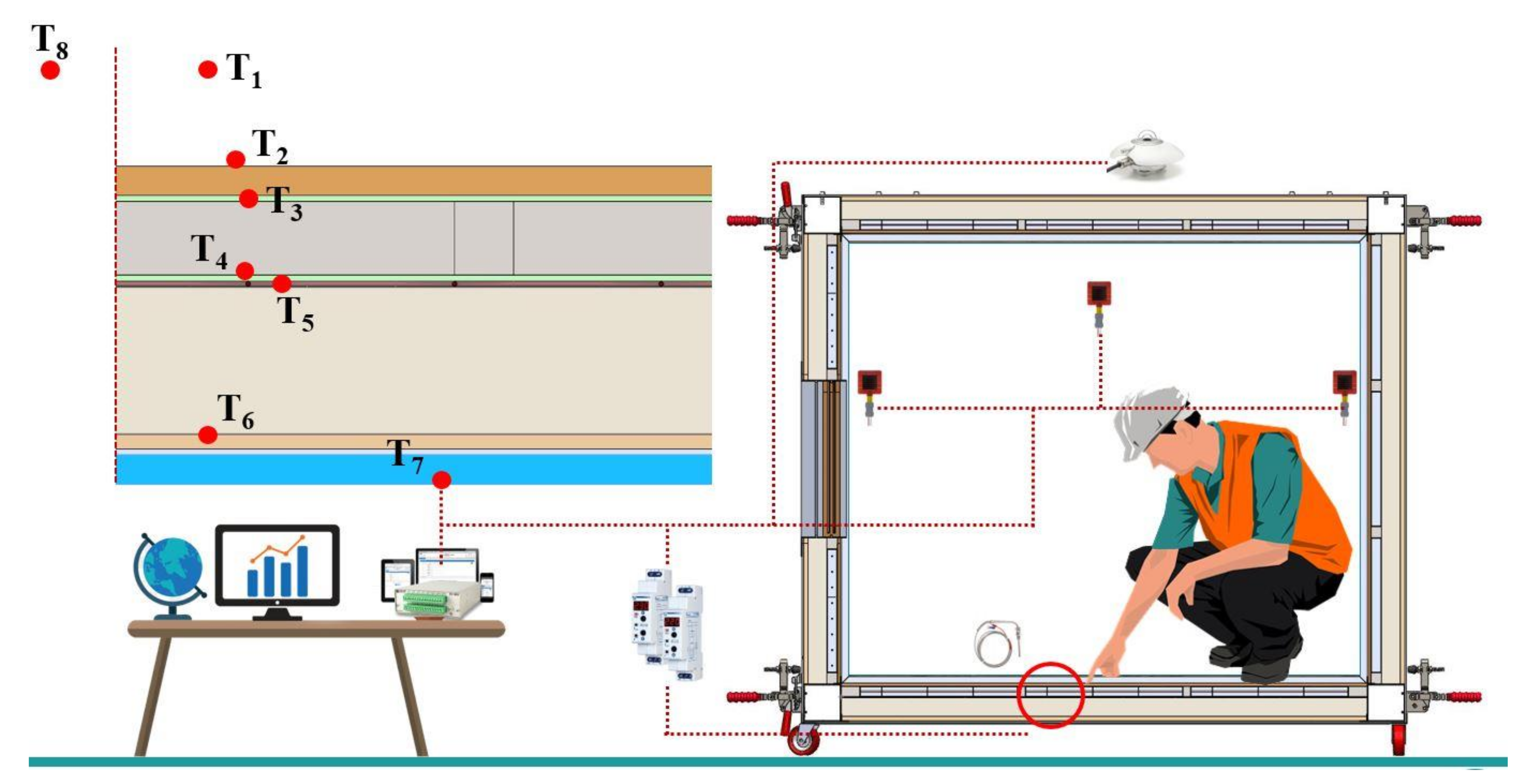
8.4. Measurement Instrumentations
8.5. Economical Study for the Prototype
9. Conclusions and Recommendations
- -
- Phase change material serving as latent heat storage system is a promising technology that permits building energy consumption reduction and thermal comfort sustainability.
- -
- Experimental studies were classified into four categories based on the size of the used facility:
- •
- Small-scale prototypes do have plenty of advantages—e.g., variable control, etc.—with a risk of not accurately reflecting reality.
- •
- Large-scale prototypes are expensive, but have a high level of matching real weather performance.
- •
- Retrofitting applications are limited in possibilities
- •
- Laboratory-based studies are easily adapted but includes high level of uncertainty compared to other realistic studies (utilizing prototypes).
- -
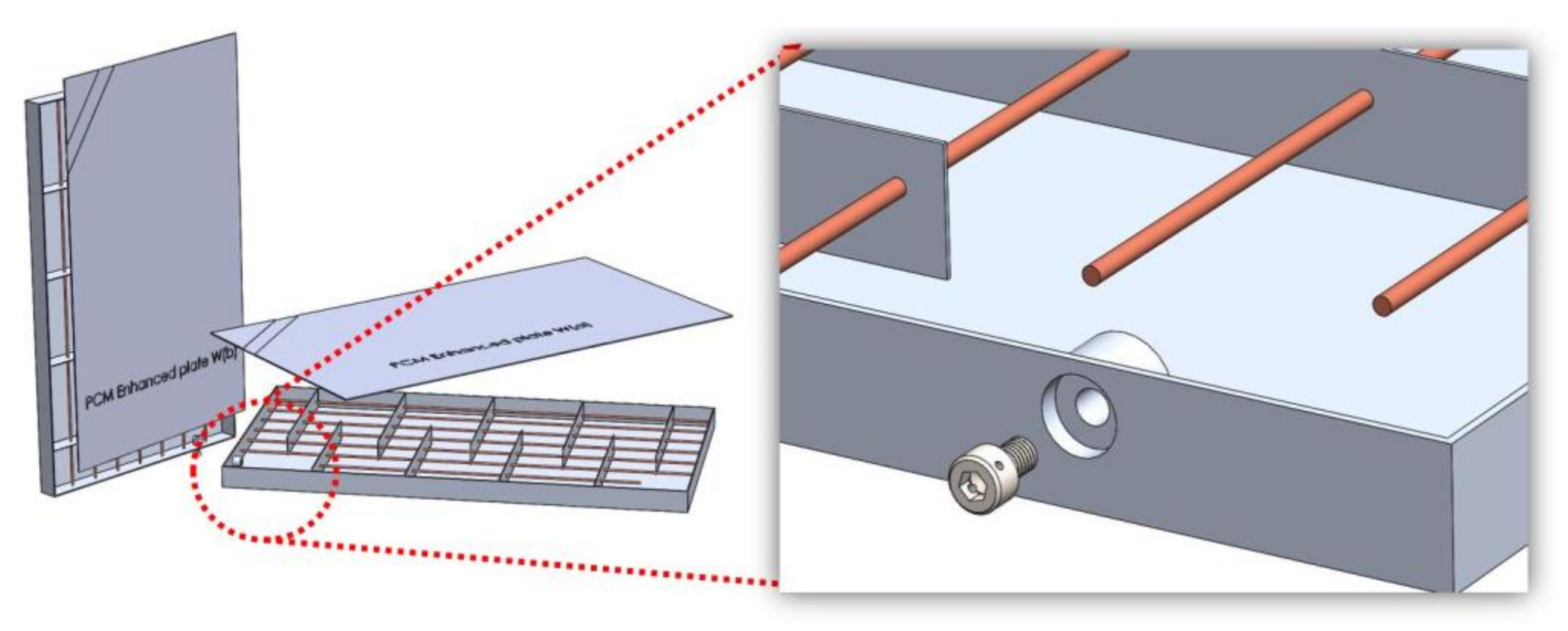
- Heat transfer enhancement for the incorporated PCM is critical for diminishing its incomplete solidification is solved by the designed enhanced macro-encapsulated plates.
- -
- A new design of an advanced modular prototype: ‘ThermoGreen®’ is proposed and is proven to allow experimental investigation of several PCM applications and their combinations toward NZEB.
- -
- Experimental optimization is a major capability offered by the designed prototype (variable thickness, position, material, application, etc.)
Author Contributions
Funding
Institutional Review Board Statement
Informed Consent Statement
Data Availability Statement
Conflicts of Interest
References
- Du, K.; Calautit, J.; Wang, Z.; Wu, Y.; Liu, H. A Review of the Applications of Phase Change Materials in Cooling, Heating and Power Generation in Different Temperature Ranges. Appl. Energy 2018, 220, 242–273. [Google Scholar] [CrossRef]
- Plytaria, M.T.; Bellos, E.; Tzivanidis, C.; Antonopoulos, K.A. Numerical Simulation of a Solar Cooling System with and without Phase Change Materials in Radiant Walls of a Building. Energy Convers. Manag. 2019, 188, 40–53. [Google Scholar] [CrossRef]
- Liu, J.; Mei, C.; Wang, H.; Shao, W.; Xiang, C. Powering an Island System by Renewable Energy—A Feasibility Analysis in the Maldives. Appl. Energy 2018, 227, 18–27. [Google Scholar] [CrossRef]
- Peker, M.; Kocaman, A.S.; Kara, B.Y. Benefits of Transmission Switching and Energy Storage in Power Systems with High Renewable Energy Penetration. Appl. Energy 2018, 228, 1182–1197. [Google Scholar] [CrossRef]
- Zia, M.F.; Elbouchikhi, E.; Benbouzid, M. Microgrids Energy Management Systems: A Critical Review on Methods, Solutions, and Prospects. Appl. Energy 2018, 222, 1033–1055. [Google Scholar] [CrossRef]
- Husein, M.; Chung, I.Y. Optimal Design and Financial Feasibility of a University Campus Microgrid Considering Renewable Energy Incentives. Appl. Energy 2018, 225, 273–289. [Google Scholar] [CrossRef]
- Zhu, C.; Li, B.; Yan, S.; Luo, Q.; Li, C. Experimental Research on Solar Phase Change Heat Storage Evaporative Heat Pump System. Energy Convers. Manag. 2021, 229, 113683. [Google Scholar] [CrossRef]
- Wu, D.; Rahim, M.; El, M.; Djedjig, R.; Bennacer, R.; Liu, B. Experimental Investigation on the Hygrothermal Behavior of a New Multilayer Building Envelope Integrating PCM with Bio-Based Material. Build. Environ. 2021, 201, 107995. [Google Scholar] [CrossRef]
- IEA. Global Energy & CO2 Status Report 2019; IEA: Paris, France, 2019. [Google Scholar]
- Preet, S. Water and Phase Change Material Based Photovoltaic Thermal Management Systems: A Review. Renew. Sustain. Energy Rev. 2018, 82, 791–807. [Google Scholar] [CrossRef]
- Zeinelabdein, R.; Omer, S.; Gan, G. Critical Review of Latent Heat Storage Systems for Free Cooling in Buildings. Renew. Sustain. Energy Rev. 2018, 82, 2843–2868. [Google Scholar] [CrossRef]
- Mehdaoui, F.; Hazami, M.; Messaouda, A.; Taghouti, H.; Guizani, A. Thermal Testing and Numerical Simulation of PCM Wall Integrated inside a Test Cell on a Small Scale and Subjected to the Thermal Stresses. Renew. Energy 2018, 135, 597–607. [Google Scholar] [CrossRef]
- Saeed, R.M.; Schlegel, J.P.; Castano, C.; Sawafta, R.; Kuturu, V. Preparation and Thermal Performance of Methyl Palmitate and Lauric Acid Eutectic Mixture as Phase Change Material (PCM). J. Energy Storage 2017, 13, 418–424. [Google Scholar] [CrossRef]
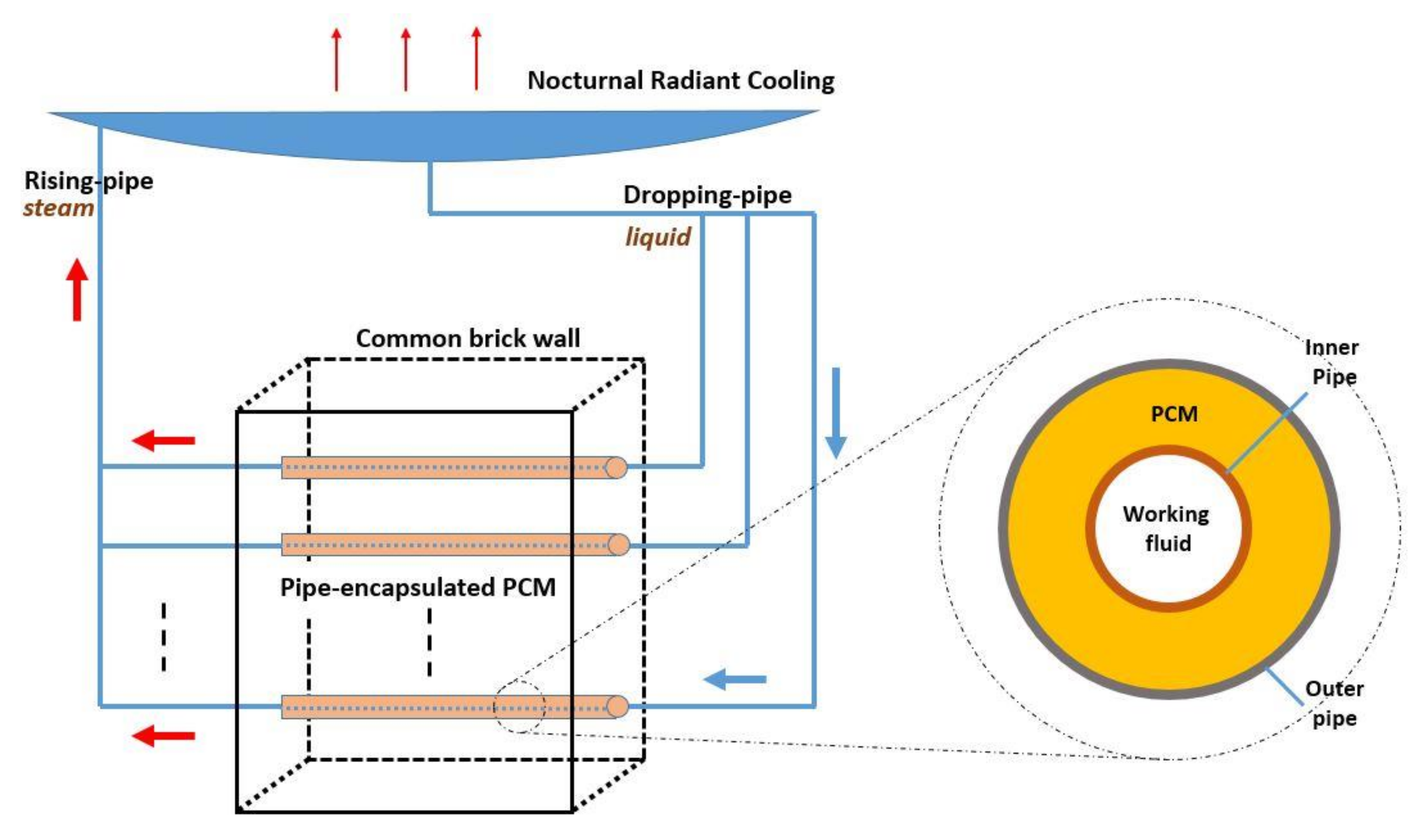
- Yan, T.; Luo, Y.; Xu, T.; Wu, H.; Xu, X.; Li, J. Experimental Study of the Coupled Wall System of Pipe-Encapsulated PCM Wall and Nocturnal Sky Radiator for Self-Activated Heat Removal. Energy Build. 2021, 241, 110964. [Google Scholar] [CrossRef]
- Memarian, S.; Mohammad, B.; Fayaz, R.; Asadi, S. Single and Combined Phase Change Materials: Their Effect on Seasonal Transition Period. Energy Build. 2018, 169, 453–472. [Google Scholar] [CrossRef]
- Erlbeck, L.; Schreiner, P.; Fasel, F.; Methner, F.; Rädle, M. Investigation of Different Materials for Macroencapsulation of Salt Hydrate Phase Change Materials for Building Purposes. Constr. Build. Mater. 2018, 180, 512–518. [Google Scholar] [CrossRef]
- Drissi, S.; Ling, T.; Hung, K.; Eddhahak, A. A Review of Microencapsulated and Composite Phase Change Materials: Alteration of Strength and Thermal Properties of Cement-Based Materials. Renew. Sustain. Energy Rev. 2019, 110, 467–484. [Google Scholar] [CrossRef]
- Marin, P.; Saffari, M.; De Gracia, A.; Zhu, X.; Farid, M.M.; Cabeza, L.F.; Ushak, S. Energy Savings Due to the Use of PCM for Relocatable Lightweight Buildings Passive Heating and Cooling in Different Weather Conditions. Energy Build. 2016, 129, 274–283. [Google Scholar] [CrossRef] [Green Version]
- Fateh, A.; Klinker, F.; Brütting, M.; Weinläder, H. Numerical and Experimental Investigation of an Insulation Layer with Phase Change Materials (PCMs). Energy Build. 2017, 153, 231–240. [Google Scholar] [CrossRef]
- Young, B.A.; Falzone, G.; Wei, Z.; Sant, G.; Pilon, L. Reduced-Scale Experiments to Evaluate Performance of Composite Building Envelopes Containing Phase Change Materials. Constr. Build. Mater. 2018, 162, 584–595. [Google Scholar] [CrossRef]
- Lee, K.O.; Medina, M.A.; Raith, E.; Sun, X. Assessing the Integration of a Thin Phase Change Material ( PCM ) Layer in a Residential Building Wall for Heat Transfer Reduction and Management Q. Appl. Energy 2014, 137, 699–706. [Google Scholar] [CrossRef]
- Yang, L.; Huang, J.; Zhou, F. Thermophysical Properties and Applications of Nano-Enhanced PCMs: An Update Review. Energy Convers. Manag. 2020, 214, 112876. [Google Scholar] [CrossRef]
- Liu, A.F.; Zhu, J.; Liu, J.; Ma, B. Preparation and Properties of Capric-Stearic Acid / White Carbon Black Composite for Thermal Storage in Building Envelope. Energy Build. 2017, 158, 1781–1789. [Google Scholar] [CrossRef]
- Kara, Y.; Kurnuc, A. Performance of Coupled Novel Triple Glass and Phase Change Material Wall in the Heating Season: An Experimental Study. Sol. Energy 2012, 86, 2432–2442. [Google Scholar] [CrossRef]
- Farid, M.M.; Khudhair, A.M.; Razack, S.; Al-Hallaj, S. A Review on Phase Change Energy Storage: Materials and Applications. Energy Convers. Manag. 2004, 45, 1597–1615. [Google Scholar] [CrossRef]
- Li, C.; Yu, H.; Song, Y.; Liu, Z. Novel Hybrid Microencapsulated Phase Change Materials Incorporated Wallboard for Year-Long Year Energy Storage in Buildings. Energy Convers. Manag. 2019, 183, 791–802. [Google Scholar] [CrossRef]
- Wei, G.; Wang, G.; Xu, C.; Ju, X.; Xing, L.; Du, X.; Yang, Y. Selection Principles and Thermophysical Properties of High Temperature Phase Change Materials for Thermal Energy Storage: A Review. Renew. Sustain. Energy Rev. 2017, 81, 1771–1786. [Google Scholar] [CrossRef]
- Morrison, D.J.; Abdel-Khalik, S.I. Effects of Phase-Change Energy Storage on the Performance of Air-Based and Liquid-Based Solar Heating Systems. Sol. Energy 1978, 20, 57–67. [Google Scholar] [CrossRef]
- Ghoneim, A.A. Comparison of Theoretical Models of Phase Change and Sensible Heat Storage for Air and Water-Based Solar Heating Systems. Sol. Energy 1989, 42, 209–220. [Google Scholar] [CrossRef]
- Faraj, K.; Khaled, M.; Faraj, J.; Hachem, F.; Castelain, C. Phase Change Material Thermal Energy Storage Systems for Cooling Applications in Buildings: A Review. Renew. Sustain. Energy Rev. 2019, 119, 109579. [Google Scholar] [CrossRef]
- Chhugani, B.; Klinker, F.; Weinlaeder, H.; Reim, M. Energetic Performance of Two Different PCM Wallboards and Their Regeneration Behavior in Office Rooms. Energy Procedia 2017, 122, 625–630. [Google Scholar] [CrossRef]
- Barzin, R.; Chen, J.J.J.; Young, B.R.; Farid, M.M. Application of PCM Underfloor Heating in Combination with PCM Wallboards for Space Heating Using Price Based Control System. Appl. Energy 2015, 148, 39–48. [Google Scholar] [CrossRef]
- Faraj, K.; Faraj, J.; Hachem, F.; Bazzi, H.; Khaled, M.; Castelain, C. Analysis of Underfloor Electrical Heating System Integrated with Coconut Oil-PCM Plates. Appl. Therm. Eng. 2019, 158, 113778. [Google Scholar] [CrossRef]
- Souayfane, F.; Fardoun, F.; Biwole, P.H. Phase Change Materials (PCM) for Cooling Applications in Buildings: A Review. Energy Build. 2016, 129, 396–431. [Google Scholar] [CrossRef]
- Giro-paloma, J.; Martínez, M.; Cabeza, L.F.; Fernández, A.I. Types, Methods, Techniques, and Applications for Microencapsulated Phase Change Materials (MPCM): A Review. Renew. Sustain. Energy Rev. 2016, 53, 1059–1075. [Google Scholar] [CrossRef] [Green Version]
- Kasaeian, A.; bahrami, L.; Pourfayaz, F.; Khodabandeh, E.; Yan, W.M. Experimental Studies on the Applications of PCMs and Nano-PCMs in Buildings: A Critical Review. Energy Build. 2017, 154, 96–112. [Google Scholar] [CrossRef]
- Tao, Y.B.; He, Y. A Review of Phase Change Material and Performance Enhancement Method for Latent Heat Storage System. Renew. Sustain. Energy Rev. 2018, 93, 245–259. [Google Scholar] [CrossRef]
- Kylili, A.; Fokaides, P.A. Life Cycle Assessment (LCA) of Phase Change Materials (PCMs) for Building Applications: A Review. J. Build. Eng. 2016, 6, 133–143. [Google Scholar] [CrossRef]
- Navarro, L.; De Gracia, A.; Colclough, S.; Browne, M.; Mccormack, S.J.; Grif, P.; Cabeza, L.F. Thermal Energy Storage in Building Integrated Thermal Systems: A Review. Part 1. Active Storage Systems. Renew. Energy 2016, 88, 526–547. [Google Scholar] [CrossRef] [Green Version]
- Navarro, L.; De Gracia, A.; Niall, D.; Castell, A.; Browne, M.; Mccormack, S.J.; Grif, P.; Cabeza, L.F. Thermal Energy Storage in Building Integrated Thermal Systems: A Review. Part 2. Integration as Passive System. Renew. Energy 2016, 85, 1334–1356. [Google Scholar] [CrossRef] [Green Version]
- Mengjie, S.; Fuxin, N.; Ning, M.; Yanxin, H.; Shiming, D. Review on Building Energy Performance Improvement Using Phase Change Materials. Energy Build. 2018, 158, 776–793. [Google Scholar] [CrossRef]
- Lizana, J.; Chacartegui, R.; Barrios-padura, A.; Ortiz, C. Advanced Low-Carbon Energy Measures Based on Thermal Energy Storage in Buildings: A Review. Renew. Sustain. Energy Rev. 2018, 82, 3705–3749. [Google Scholar] [CrossRef]
- Ben Romdhane, S.; Amamou, A.; Ben Khalifa, R.; Saïd, N.M.; Younsi, Z.; Jemni, A. A Review on Thermal Energy Storage Using Phase Change Materials in Passive Building Applications. J. Build. Eng. 2020, 32, 101563. [Google Scholar] [CrossRef]
- Li, Y.; Nord, N.; Xiao, Q. Building Heating Applications with Phase Change Material: A Comprehensive Review. J. Energy Storage 2020, 31, 101634. [Google Scholar] [CrossRef]
- Javadi, F.S.; Metselaar, H.S.C.; Ganesan, P. Performance Improvement of Solar Thermal Systems Integrated with Phase Change Materials (PCM), a Review. Sol. Energy 2020, 206, 330–352. [Google Scholar] [CrossRef]
- Magrini, A.; Lentini, G.; Cuman, S.; Bodrato, A.; Marenco, L. From Nearly Zero Energy Buildings (NZEB) to Positive Energy Buildings ( PEB ): The next Challenge—The Most Recent European Trends with Some Notes on the Energy Analysis of a Forerunner PEB Example. Dev. Built Environ. 2020, 3, 100019. [Google Scholar] [CrossRef]
- Mourid, A.; El Alami, M.; Kuznik, F. Experimental Investigation on Thermal Behavior and Reduction of Energy Consumption in a Real Scale Building by Using Phase Change Materials on Its Envelope. Sustain. Cities Soc. 2018, 41, 35–43. [Google Scholar] [CrossRef]
- Lu, S.; Zhao, Y.; Fang, K.; Li, Y.; Sun, P. Establishment and Experimental Verification of TRNSYS Model for PCM Floor Coupled with Solar Water Heating System. Energy Build. 2017, 140, 245–260. [Google Scholar] [CrossRef]
- Gholamibozanjani, G.; Farid, M. Application of an Active PCM Storage System into a Building for Heating/Cooling Load Reduction. Energy 2020, 331–358. [Google Scholar] [CrossRef]
- Gholamibozanjani, G.; Farid, M. A Comparison between Passive and Active PCM Systems Applied to Buildings. Renew. Energy 2020, 162, 113–123. [Google Scholar] [CrossRef]
- de Gracia, A.; Navarro, L.; Castell, A.; Ruiz-Pardo, Á.; Alvárez, S.; Cabeza, L.F. Experimental Study of a Ventilated Facade with PCM during Winter Period. Energy Build. 2013, 58, 324–332. [Google Scholar] [CrossRef]
- Zhou, G.; He, J. Thermal Performance of a Radiant Floor Heating System with Different Heat Storage Materials and Heating Pipes. Appl. Energy 2015, 138, 648–660. [Google Scholar] [CrossRef]
- Kong, X.; Wang, L.; Li, H.; Yuan, G.; Yao, C. Experimental Study on a Novel Hybrid System of Active Composite PCM Wall and Solar Thermal System for Clean Heating Supply in Winter. Sol. Energy 2020, 195, 259–270. [Google Scholar] [CrossRef]
- Sinka, M.; Bajare, D.; Jakovics, A.; Ratnieks, J.; Gendelis, S. Experimental Testing of Phase Change Materials in a Warm-Summer Humid Continental Climate. Energy Build. 2019, 195, 205–215. [Google Scholar] [CrossRef]
- Lee, K.O.; Medina, M.A.; Sun, X.; Jin, X. Thermal Performance of Phase Change Materials (PCM)-Enhanced Cellulose Insulation in Passive Solar Residential Building Walls. Sol. Energy 2018, 163, 113–121. [Google Scholar] [CrossRef]
- Wang, X.; Yu, H.; Li, L.; Zhao, M. Experimental Assessment on the Use of Phase Change Materials (PCMs)-Bricks in the Exterior Wall of a Full-Scale Room. Energy Convers. Manag. 2016, 120, 81–89. [Google Scholar] [CrossRef]
- Luo, C.; Xu, L.; Ji, J.; Liao, M.; Sun, D. Experimental Study of a Modified Solar Phase Change Material Storage Wall System. Energy 2017, 128, 224–231. [Google Scholar] [CrossRef] [Green Version]
- Sun, D.; Wang, L. Research on Heat Transfer Performance of Passive Solar Collector-Storage Wall System with Phase Change Materials. Energy Build. 2016, 119, 183–188. [Google Scholar] [CrossRef]
- Guarino, F.; Athienitis, A.; Cellura, M.; Bastien, D. PCM Thermal Storage Design in Buildings: Experimental Studies and Applications to Solaria in Cold Climates. Appl. Energy 2017, 185, 95–106. [Google Scholar] [CrossRef]
- Souayfane, F.; Henry, B.; Fardoun, F. Thermal Behavior of a Translucent Superinsulated Latent Heat Energy Storage Wall in Summertime. Appl. Energy 2018, 217, 390–408. [Google Scholar] [CrossRef]
- Hu, Y.; Heiselberg, P.K. A New Ventilated Window with PCM Heat Exchanger –performance Analysis and Design Optimization. Energy Build. 2018, 169, 185–194. [Google Scholar] [CrossRef]
- Li, H.; Li, J.; Xi, C.; Chen, W.; Kong, X. Experimental and Numerical Study on the Thermal Performance of Ventilated Roof Composed with Multiple Phase Change Material (VR-MPCM). Energy Convers. Manag. 2020, 213, 112836. [Google Scholar] [CrossRef]
- He, W.; Yu, C.; Yang, J.; Yu, B.; Hu, Z.; Shen, D.; Liu, X.; Qin, M.; Chen, H. Experimental Study on the Performance of a Novel RC-PCM-Wall. Energy Build. 2019, 199, 297–310. [Google Scholar] [CrossRef]
- Garg, H.; Pandey, B.; Saha, S.K.; Singh, S.; Banerjee, R. Design and Analysis of PCM Based Radiant Heat Exchanger for Thermal Management of Buildings. Energy Build. 2018, 169, 84–96. [Google Scholar] [CrossRef]
- Jobli, M.; Yao, R.; Luo, Z.; Shahrestani, M.; Li, N.; Hong, L. Numerical and Experimental Studies of a Capillary-Tube Embedded PCM Component for Improving Indoor Thermal Environment. Appl. Therm. Eng. 2019, 148, 466–477. [Google Scholar] [CrossRef]
- Fang, Y.; Ding, Y.; Tang, Y.; Liang, X.; Jin, C.; Wang, S.; Gao, X. Thermal Properties Enhancement and Application of a Novel Sodium Acetate Trihydrate-Formamide/Expanded Graphite Shape-Stabilized Composite Phase Change Material for Electric Radiant Floor Heating. Appl. Therm. Eng. 2019, 150, 1177–1185. [Google Scholar] [CrossRef]
- Guo, J.; Jiang, Y.; Wang, Y.; Zou, B. Thermal Storage and Thermal Management Properties of a Novel Ventilated Mortar Block Integrated with Phase Change Material for Floor Heating: An Experimental Study. Energy Convers. Manag. 2020, 205, 112288. [Google Scholar] [CrossRef]
- Abbas, H.M.; Jalil, J.M.; Ahmed, S.T. Experimental and Numerical Investigation of PCM Capsules as Insulation Materials Inserted into a Hollow Brick Wall. Energy Build. 2021, 246, 111127. [Google Scholar] [CrossRef]
- Kumar, P.; Rathore, S. An experimental evaluation of thermal behavior of the building envelope using macroencapsulated pcm for energy savings. Renew. Energy 2019, 149, 1300–1313. [Google Scholar] [CrossRef]
- Khan, R.J.; Bhuiyan, Z.H.; Ahmed, D.H. Investigation of Heat Transfer of a Building Wall in the Presence of Phase Change Material (PCM). Energy Built Environ. 2020, 1, 199–206. [Google Scholar] [CrossRef]
- Zhu, N.; Hu, N.; Hu, P.; Lei, F.; Li, S. Experiment Study on Thermal Performance of Building Integrated with Double Layers Shape-Stabilized Phase Change Material Wallboard. Energy 2018, 167, 1164–1180. [Google Scholar] [CrossRef]
- Berardi, U.; Soudian, S. Experimental Investigation of Latent Heat Thermal Energy Storage Using PCMs with Different Melting Temperatures for Building Retrofit. Energy Build. 2019, 185, 180–195. [Google Scholar] [CrossRef]
- Sun, X.; Medina, M.A.; Lee, K.O.; Jin, X. Laboratory Assessment of Residential Building Walls Containing Pipe-Encapsulated Phase Change Materials for Thermal Management. Energy 2018, 163, 383–391. [Google Scholar] [CrossRef]
- Zhang, Y.; Sun, X.; Medina, M.A. Experimental Evaluation of Structural Insulated Panels Outfitted with Phase Change Materials. Appl. Therm. Eng. 2020, 178, 115454. [Google Scholar] [CrossRef]
- Meng, E.; Yu, H.; Zhou, B. Study of the Thermal Behavior of the Composite Phase Change Material (PCM) Room in Summer and Winter. Appl. Therm. Eng. 2017, 126, 212–225. [Google Scholar] [CrossRef]
- Cheng, W.; Xie, B.; Zhang, R.; Xu, Z.; Xia, Y. Effect of Thermal Conductivities of Shape Stabilized PCM on Under-Floor Heating System. Appl. Energy 2015, 144, 10–18. [Google Scholar] [CrossRef]
- Lu, S.; Xu, B.; Tang, X. Experimental Study on Double Pipe PCM Floor Heating System under Different Operation Strategies. Renew. Energy 2020, 145, 1280–1291. [Google Scholar] [CrossRef]
- Stritih, U.; Charvat, P.; Koželj, R.; Klimes, L.; Osterman, E.; Ostry, M.; Butala, V. PCM Thermal Energy Storage in Solar Heating of Ventilation Air—Experimental and Numerical Investigations. Sustain. Cities Soc. 2017, 37, 104–115. [Google Scholar] [CrossRef]
- Lamnatou, C.; Motte, F.; Notton, G.; Chemisana, D.; Cristofari, C. Building-Integrated Solar Thermal System with/without Phase Change Material: Life Cycle Assessment Based on ReCiPe, USEtox and Ecological Footprint. J. Clean. Prod. 2018, 193, 672–683. [Google Scholar] [CrossRef]
- Nada, S.A.; Alshaer, W.G.; Saleh, R.M. Experimental Investigation of PCM Transient Performance in Free Cooling of the Fresh Air of Air Conditioning Systems. J. Build. Eng. 2020, 29, 101153. [Google Scholar] [CrossRef]
- Wang, C.; Huang, X.; Deng, S.; Long, E.; Niu, J. An Experimental Stydy on Applying PCMs to Disaster-Relief Prefabricated Temporary Houses for Improving Internal Thermal Environment in Summer. Energy Build. 2018, 179, 301–310. [Google Scholar] [CrossRef]
- Lee, K.O.; Medina, M.; Sun, X. On the Use of Plug-and-Play Walls (PPW) for Evaluating Thermal Enhancement Technologies for Building Enclosures: Evaluation of a Thin Phase Change Material (PCM) Layer. Energy Build. 2015, 86, 86–92. [Google Scholar] [CrossRef]
- Vik, T.A.; Madessa, H.B.; Aslaksrud, P.; Folkedal, E.; Øvrevik, O.S. Thermal Performance of an Office Cubicle Integrated with a Bio-Based PCM: Experimental Analyses. Energy Procedia 2017, 111, 609–618. [Google Scholar] [CrossRef]
- Li, Y.; Darkwa, J.; Kokogiannakis, G.; Su, W. Phase Change Material Blind System for Double Skin Façade Integration: System Development and Thermal Performance Evaluation. Appl. Energy 2019, 252, 113376. [Google Scholar] [CrossRef]
- Favier, P.; Zalewski, L.; Lassue, S.; Anwar, S. Designing an Automatic Control System for the Improved Functioning of a Solar Wall with Phase Change Material (PCM). Open J. Energy Effic. 2016, 5, 19–29. [Google Scholar] [CrossRef] [Green Version]
- Gracia, A. De Dynamic Building Envelope with PCM for Cooling Purposes—Proof of Concept. Appl. Energy 2019, 235, 1245–1253. [Google Scholar] [CrossRef]
- Guo, J.; Zou, B.; Wang, Y.; Jiang, Y. Space Heating Performance of Novel Ventilated Mortar Blocks Integrated with Phase Change Material for Floor Heating. Build. Environ. 2020, 185, 107175. [Google Scholar] [CrossRef]
- Yan, T.; Gao, J.; Xu, X.; Xu, T.; Ling, Z.; Yu, J. International Journal of Thermal Sciences Dynamic Simpli Fi Ed PCM Models for the Pipe-Encapsulated PCM Wall System for Self-Activated Heat Removal. Int. J. Therm. Sci. 2019, 144, 27–41. [Google Scholar] [CrossRef]
- Qiao, Y.; Cao, T.; Muehlbauer, J.; Hwang, Y.; Radermacher, R. Experimental Study of a Personal Cooling System Integrated with Phase Change Material. Appl. Therm. Eng. 2020, 170, 115026. [Google Scholar] [CrossRef]
- Xu, T.; Chiu, J.N.; Palm, B.; Sawalha, S. Experimental Investigation on Cylindrically Macro-Encapsulated Latent Heat Storage for Space Heating Applications. Energy Convers. Manag. 2019, 182, 166–177. [Google Scholar] [CrossRef]
- Saeed, R.M.; Schlegel, J.P.; Sawafta, R.; Kalra, V. Plate Type Heat Exchanger for Thermal Energy Storage and Load Shifting Using Phase Change Material. Energy Convers. Manag. 2019, 181, 120–132. [Google Scholar] [CrossRef]
- Sun, H.; Lin, B.; Lin, Z.; Zhu, Y. Experimental Study on a Novel Flat-Heat-Pipe Heating System Integrated with Phase Change Material and Thermoelectric Unit. Energy 2019, 189, 116181. [Google Scholar] [CrossRef]
- Sun, X.; Chu, Y.; Medina, M.A.; Mo, Y.; Fan, S.; Liao, S. Experimental Investigations on the Thermal Behavior of Phase Change Material (PCM) in Ventilated Slabs. Appl. Therm. Eng. 2019, 148, 1359–1369. [Google Scholar] [CrossRef]
- Wadhawan, A.; Dhoble, A.S.; Gawande, V.B. Analysis of the Effects of Use of Thermal Energy Storage Device (TESD) in Solar Air Heater. Alex. Eng. J. 2017, 57, 1173–1183. [Google Scholar] [CrossRef]
- Abuşka, M.; Şevik, S.; Kayapunar, A. A Comparative Investigation of the Effect of Honeycomb Core on the Latent Heat Storage with PCM in Solar Air Heater. Appl. Therm. Eng. 2018, 148, 684–693. [Google Scholar] [CrossRef]
- Chen, C.Q.; Diao, Y.H.; Zhao, Y.H.; Wang, Z.Y.; Liang, L.; Wang, T.Y.; Zhu, T.T.; Ma, C. Thermal Performance of a Closed Collector-Storage Solar Air Heating System with Latent Thermal Storage: An Experimental Study. Energy 2020, 202, 117764. [Google Scholar] [CrossRef]
- Evers, A.C.; Medina, M.A.; Fang, Y. Evaluation of the Thermal Performance of Frame Walls Enhanced with Paraf Fi n and Hydrated Salt Phase Change Materials Using a Dynamic Wall Simulator. Build. Environ. 2010, 45, 1762–1768. [Google Scholar] [CrossRef]
- Ryms, M.; Klugmann-radziemska, E. Possibilities and Benefits of a New Method of Modifying Conventional Building Materials with Phase Change Materials (PCMs). Constr. Build. Mater. 2019, 211, 1013–1024. [Google Scholar] [CrossRef]
- Li, C.; Yu, H.; Song, Y.; Tang, Y.; Chen, P.; Hu, H.; Wang, M.; Liu, Z. Experimental Thermal Performance of Wallboard with Hybrid Microencapsulated Phase Change Materials for Building Application. J. Build. Eng. 2019, 28, 101051. [Google Scholar] [CrossRef]
- Drissi, S.; Ling, T.; Hung, K. Thermal Performance of a Solar Energy Storage Concrete Panel Incorporating Phase Change Material Aggregates Developed for Thermal Regulation in Buildings. Renew. Energy 2020, 160, 817–829. [Google Scholar] [CrossRef]
- Saxena, R.; Rakshit, D.; Kaushik, S.C. Experimental Assessment of Phase Change Material (PCM) Embedded Bricks for Passive Conditioning in Buildings. Renew. Energy 2020, 149, 587–599. [Google Scholar] [CrossRef]
- Wang, S.M.; Matiašovský, P.; Mihálka, P.; Lai, C.M. Experimental Investigation of the Daily Thermal Performance of a MPCM Honeycomb Wallboard. Energy Build. 2018, 159, 419–425. [Google Scholar] [CrossRef]
- Li, D.; Wu, Y.; Liu, C.; Zhang, G.; Arıcı, M. Numerical Investigation of Thermal and Optical Performance of Window Units Filled with Nanoparticle Enhanced PCM. Int. J. Heat Mass Transf. 2018, 125, 1321–1332. [Google Scholar] [CrossRef]
- Faraj, K.; Khaled, M.; Faraj, J.; Hachem, F.; Castelain, C. A Review on Phase Change Materials for Thermal Energy Storage in Buildings: Heating and Hybrid Applications. J. Energy Storage 2020, 33, 101913. [Google Scholar] [CrossRef]
- Entropy Solutions. PureTemp 20 Technical Information; Entropy Solutions: Minneapolis, MN, USA, 2020. [Google Scholar]
- Yoo, D.H.; Jeon, I.K.; Woo, B.H.; Kim, H.G. Performance of Energy Storage System Containing Cement Mortar and PCM/Epoxy/SiC Composite Fine Aggregate. Appl. Therm. Eng. 2021, 198, 117445. [Google Scholar] [CrossRef]
- Mousavi, S.; Rismanchi, B.; Brey, S.; Aye, L. Lessons Learned from PCM Embedded Radiant Chilled Ceiling Experiments in Melbourne. Energy Rep. 2022, 8, 54–61. [Google Scholar] [CrossRef]
- Wang, Z.; Qiao, Y.; Liu, Y.; Bao, J.; Gao, Q.; Chen, J.; Yao, H.; Yang, L. Thermal Storage Performance of Building Envelopes for Nearly-Zero Energy Buildings during Cooling Season in Western China: An Experimental Study. Build. Environ. 2021, 194, 107709. [Google Scholar] [CrossRef]
- Cai, Y.; Song, L.; He, Q.; Yang, D.; Hu, Y. Preparation, Thermal and Flammability Properties of a Novel Form-Stable Phase Change Materials Based on High Density Polyethylene/ Poly (Ethylene-Co-Vinyl Acetate)/Organophilic Montmorillonite Nanocomposites/Paraffin Compounds. Energy Convers. Manag. 2008, 49, 2055–2062. [Google Scholar] [CrossRef]
- Bogatu, D.; Kazanci, O.B.; Olesen, B.W. An Experimental Study of the Active Cooling Performance of a Novel Radiant Ceiling Panel Containing Phase Change Material (PCM). Energy Build. 2021, 243. [Google Scholar] [CrossRef]
- Larwa, B.; Cesari, S.; Bottarelli, M. Study on Thermal Performance of a PCM Enhanced Hydronic Radiant Floor Heating System. Energy 2021, 225, 120245. [Google Scholar] [CrossRef]
- Young, H.D. Values for Diamond and Silica Aerogel from CRC Handbook of Chemistry and Physics. Available online: http://hyperphysics.phy-astr.gsu.edu/hbase/Tables/thrcn.html (accessed on 30 September 2020).
- Thermtest Common Material Thermal Properties. Available online: https://thermtest.com/materials-database (accessed on 30 September 2020).
- Owens-Corning Foamular Extruded Plystyrene (XPS) Insulation: SI and IP Units for Selected Properties. Available online: https://dcpd6wotaa0mb.cloudfront.net/mdms/dms/EIS/10015703/10015703-FOAMULAR-SI-and-I-P-Units-for-Selected-Properties-Tech.-Bulletin.pdf (accessed on 30 September 2020).
- Hammond, G.; Jones, C. Enventory of Carbon and Energy, 2nd ed.; Elsevier: Amsterdam, The Netherlands, 2011. [Google Scholar]
- Engineering Toolbox Specific Heat of Some Common Substances. Available online: https://www.engineeringtoolbox.com/specific-heat-capacity-d_391.html (accessed on 30 September 2020).
- Maclean, J.D.; Madison, W. Thermal Conductivity of Wood. Heatig Pip. Air Cond. 1941, 13, 380–391. [Google Scholar]
- 3A Composites ALUCOBOND Technical Data. Available online: https://alucobond.com.sg/products/alucobond/technical-data/ (accessed on 30 September 2020).
- Ji, R.; Wei, S.; Xia, Y.; Huang, C.; Huang, Y.; Zhang, H. Enhanced Thermal Performance of Form-Stable Composite Phase-Change Materials Supported by Novel Porous Carbon Spheres for Thermal Energy Storage. J. Energy Storage 2020, 27, 101134. [Google Scholar] [CrossRef]
- Mayilvelnathan, V.; Arasu, A.V. Characterisation and Thermophysical Properties of Graphene Nanoparticles Dispersed Erythritol PCM for Medium Temperature Thermal Energy Storage Applications. Thermochim. Acta 2019, 676, 94–103. [Google Scholar] [CrossRef]
- Aqib, M.; Hussain, A.; Muhammad Ali, H.; Naseer, A.; Jamil, F. Case Studies in Thermal Engineering Experimental Case Studies of the Effect of Al 2 O 3 and MWCNTs Nanoparticles on Heating and Cooling of PCM. Case Stud. Therm. Eng. 2020, 22, 100753. [Google Scholar] [CrossRef]
- Righetti, G.; Savio, G.; Meneghello, R.; Doretti, L.; Mancin, S. Experimental Study of Phase Change Material (PCM) Embedded in 3D Periodic Structures Realized via Additive Manufacturing. Int. J. Therm. Sci. 2020, 153, 106376. [Google Scholar] [CrossRef]
- dos Santos, F.S.; Ismail, K.A.R.; Lino, F.A.M.; Arabkoohsar, A.; Lago, T.G.S. Parametric Investigation of the Enhancing Effects of Finned Tubes on the Solidification of PCM. Int. J. Heat Mass Transf. 2020, 152, 119485. [Google Scholar] [CrossRef]
- Gil, A.; Peiró, G.; Oró, E.; Cabeza, L.F. Experimental Analysis of the Effective Thermal Conductivity Enhancement of PCM Using Finned Tubes in High Temperature Bulk Tanks. Appl. Therm. Eng. 2018, 142, 736–744. [Google Scholar] [CrossRef]
- Lin, Y.; Jia, Y.; Alva, G.; Fang, G. Review on Thermal Conductivity Enhancement, Thermal Properties and Applications of Phase Change Materials in Thermal Energy Storage. Renew. Sustain. Energy Rev. 2018, 82, 2730–2742. [Google Scholar] [CrossRef]
- Iasiello, M.; Mameli, M.; Filippeschi, S.; Bianco, N. Metal Foam/PCM Melting Evolution Analysis: Orientation and Morphology Effects. Appl. Therm. Eng. 2021, 187, 116572. [Google Scholar] [CrossRef]
- Ghahremannezhad, A.; Xu, H.; Salimpour, M.R.; Vafai, K.; Wang, P. Thermal Performance Analysis of Phase Change Materials (PCMs); Elsevier Ltd.: Amsterdam, The Netherlands, 2020; ISBN 8415683111. [Google Scholar]
- Baby, R.; Balaji, C. Experimental Investigations on Thermal Performance Enhancement and Effect of Orientation on Porous Matrix Filled PCM Based Heat Sink. Int. Commun. Heat Mass Transf. 2013, 46, 27–30. [Google Scholar] [CrossRef]
- Vanaga, R.; Blumberga, A.; Freimanis, R.; Mols, T.; Blumberga, D. Solar Facade Module for Nearly Zero Energy Building. Energy 2018, 157, 1025–1034. [Google Scholar] [CrossRef]


| Classification Criteria | Classification Based on Test Facility | |||
|---|---|---|---|---|
| Large-Scale Prototype | Small-Scale Prototype | Retrofitting in Full-Scale Compartment | Laboratory-Based Test Facility | |
| Purpose | Test thermal behavior, heating/cooling load management, thermal comfort | Test thermal behavior, heating/cooling load management, thermal comfort | Test thermal behavior, heating/cooling load management, thermal comfort | Test thermal behavior |
| Method | Building up large hut subjected to real weather | Building up small hut subjected to real/artificial weather | Installing systems to already built full-scale buildings subjected to real weather | Building up systems (partitions) under controlled laboratory environment |
| Volume | V ≥ 5 m3 | 1 m3 ≤ V ≤ 5 m3 | V ≥ 5 m3 | No complete hut or V ≤ 1 m3 |
| PCM Used | Type | Synthetic/Commercial | Application | Incorporation Method | Melting Temperature, °C | Latent Heat, kJ/kg | Thermal Conductivity, W/m·K | Specific Heat, kJ/kg·K | Reference |
|---|---|---|---|---|---|---|---|---|---|
| Rubitherm® RT28HC | Paraffin-based | Commercial | Cooling radiative wall | Macro-encapsulation | 28 | 250 | 0.2 | 2 | [63] |
| RT27 | Paraffin-based | Commercial | Cooling wall | Pipe macro-encapsulation | 28 | 147 | 0.2 | - | [73] |
| PCMTB | Paraffin-based | Commercial | Cooling wall | Micro-encapsulation | 20.6 | 73.4 | - | - | [82] |
| MSPCMW | Paraffin-based | Commercial | Trombe wall | Macro-encapsulation | 25–27 | 160 | 0.6 | - | [57] |
| PCM-cellulose mixture | Paraffin-based | Synthetic | Cooling wall | Direct mixing | 28 | 60.45 | 0.2 | - | [55] |
| Save® HS24 | Inorganic | Commercial | Radiant roof | Macro-encapsulation | 23-32 | 199 | 1.05 | 2.42 (l) 2.07 (s) | [64] |
| DuPontTM Energain® wallboards | Paraffin-based | Commercial | Heating walls | Macro-encapsulated | 20–35 | 72.4 | 0.18 | - | [47] |
| SP29 | Inorganic | Commercial | Hybrid envelope | Macro-encapsulated | 28–30 | 190 | 0.6 | - | [75] |
| RT18 | Paraffin-based | Commercial | Hybrid envelope | Macro-encapsulated | 17–19 | 225 | 0.2 | - | [75] |
| - | - | Commercial | Heating solar wall | - | 18–24 | 70 | - | 2.5 | [59] |
| CAHA PCM | Organic mixture | Synthetic | Heating PCM floor with SWH | Pipe macro-encapsulation | 19–25 | 266.28 | 0.148 (l) 0.116 (s) | 2.21 (l) 1.975 (s) | [48] |
| PX35 with epoxy resin | Organic | Synthetic | Cooling PCM blind for DSF | Micro-encapsulated | 28.2–38.5 | 77.8 | 0.1 (for PX35) | 1.6 (for PX35) | [84] |
| - | Inorganic | - | Cooling walls | Macro-encapsulation | 18-26 | 216 | 0.25(l) 0.5 (s) | 1.78 | [81] |
| DuPontTM Energain® wallboards | Paraffin-based | Commercial | Cooling walls and ceiling | Macro-encapsulated | 21.7 | 70 | 0.117 | 2.5 | [72] |
| Bio-PCM ENRG BlanketTM | Organic | Commercial | Cooling walls and ceiling | Macro-encapsulated | 25 | 165-200 | 0.128 | 2.1 | [72] |
| RT-26 | Paraffin-based | Commercial | Cooling PCMSIP walls, floor and roof | Macro-encapsulated | 26.1–32.2 | 131 | 0.2 | 2 | [74] |
| PureTemp 37 | Organic | Commercial | Active personal cooling system | Macro-encapsulated | 37 | 210 | 0.15 (l) 0.25 (s) | 2.63 (l) 2.21 (s) | [89] |
| ZDJN-28 | Paraffin-based | Commercial | Active cooling ventilated slabs | Shape-stabilized | 22.1–32.5 | 231.2 | 0.16 (l) 0.36 (s) | 2.3 (l) 2.15 (s) | [93] |
| A23 Plus-ice | Paraffin-based | Commercial | Hybrid capillary tube PCM wall and ceiling | Micro-encapsulated | 21 | 210 | 0.18 | 2.22 | [65] |
| PCM–RT25HC | Organic | Commercial | Hybrid active PCM storage unit | Macro-encapsulated | 22–26 | 230 | 0.2 | 2 | [49] |
| SavE® OM-37 | Inorganic | Commercial | Cooling walls and roof | Macro-encapsulated | 36–40 | 218 | 0.13 (l) 0.16 (s) | - | [69] |
| Paraffin wax | Paraffin-based | Commercial | Hybrid wall | Macro-encapsulated | 42–72 | 250 | 0.25 | 1.84 | [70] |
| Hydrate Salt | Inorganic | Commercial | Cooling Insulation wall | Direct mixing | 29 | 175 | 1 | 2.3 (l) 1.4 (s) | [97] |
| Paraffin PCM | Paraffin-based | Commercial | Cooling Insulation wall | Direct mixing | 28 | 179 | 0.2 | 2.4 (l) 1.8 (s) | [97] |
| Paraffin wax 22 | Paraffin-based | Commercial | Ventilated window | Immersion | 22 | 216 | 0.18 | 2.85 | [61] |
| Hydrated salt | Inorganic | Synthetic | Cooling wall | Macro-encapsulated | 31.4 | 149.9 | - | - | [21] |
| Fatty-acid Eutectic | Organic eutectic | Synthetic | Hybrid PCM-TIM wall | Macro-encapsulated | 21.3 | 152 | 0.182 | 2.09 (l) 1.67 (s) | [60] |
| PCM-27 | - | - | Cooling PCM wall | Macro-encapsulated | 27 | 172.42 | 0.58 (l) 1.05 (s) | 2.22 (l) 1.42 (s) | [12] |
| RT28 with EG | Paraffin-based | Synthetic | Self-activated cooling wall | Macro-encapsulated | 26.5–28.5 | 160.2 | 9.8 (l) 9.5 (s) | 1.981 | [88] |
| Pure Temp PT20 | Bio-based | Commercial | Cooling walls and ceiling | Impregnation | 20 | 171 | 0.14 (l) 0.23 (s) | 2.15 (l) 2.07 (s) | [32,105] |
| Bio-PCM Q25 M51 | Bio-based | Commercial | Hybrid walls and radiant ceiling | Macro-encapsulation | 25 | 200 | 0.2 | - | [54] |
| Testing Criteria | Prototype Application (s) | Interchangeable Sections | Climate | Testing Duration | Design Specifications | Instrumentation | Ref. | ||
|---|---|---|---|---|---|---|---|---|---|
| Window | Door | ||||||||
| Laboratory test facility | TES Aggregate (Mortar) | Top cover | Laboratory environment | 500 min | - | - | T-type TCs | [106] | |
| Large-scale prototype | PCM embedded radiant chilled ceiling | Ceiling panels | Melbourne, Australia | 3 months | - | - | RTD PT100, heat flux and ERS CO2 sensors, flow, power, and radio-meters | [107] | |
| Small-scale prototype | Wallboards embedded with PCM | Walls | Laboratory environment (Western China) | 2 days | - | - | K-type TCs and heat flux meters | [108] | |
| Large-scale prototype | PCM walls | - | Suzhou, China | 18 days | K-type TCs, irradiance and heat flux sensors | [109] | |||
| Large-scale prototype | Radiant PCM ceiling | Ceiling panels | Copnhagen, Denmark | 24 h | - | N.A. | Temperature and heatflux sensors | [110] | |
| Large-scale prototype | PCM radiant floor heating | - | Ferrara, Italy | 12 days | - | - | T-type TCs, heat flux meters | [111] | |
| Small-scale prototype | Radiant cooling PCM wall | - | Hot summer of Hefei, Anhui | 3 days | - | 17 Cu-constant-Cu TCs, pyranometer, hot-wire anemometer | [63] | ||
| Small-scale prototype | PCM walls | Walls | Laboratory reflecting hot Midwestern US | 120 h | - | - | T-type TCs, heat flux meter | [73] | |
| Retrofitting | PCM walls | 60 PPW panels with variable thicknesses | Hot summer | Full year (3 days presented) | 4200 m2 (M2SEC) | N.A. | N.A. | T-type TCs, heat flux meter | [82] |
| Large-scale prototype | Trombe wall | - | Hefei, Anhui. | 3 days | N.A. | N.A. | N.A. | Cu-constantan TCs, pyranometer | [57] |
| Large-scale prototype | PCM-insulation wall | - | DOE Region 4, USA | 3 days | N.A. | N.A. | T-type TCs, heat flux meter | [55] | |
| Small-scale prototype | Active radiant roof | Roof | Mumbai, India | 16 h | - | T-type TCs | [64] | ||
| Large-scale prototype | PCM walls and ceiling | - | Casablanca | 3 days (2 periods) | N.A. | N.A. | K-type TCs, weather station* (Vantage Pro 2), heat flux meter | [47] | |
| Small-scale prototype | PCM walls, floor, and roof | - | China | 6 days (2 periods) | - | K-type TCs, dolar radiation sensor | [75] | ||
| Large-scale prototype | PCM solar wall | - | Environment simulator (SSEC) Montreal, Canada | 80 h | - | Thermocouples | [59] | ||
| Large-scale prototype | PCM floor with SWH | Door and window | Tianjin, China | 15 days | N.A. | T-type TCs, heat flow meter, ultrasonic heat meter, micro-weather station | [48] | ||
| Retrofitting | PCM blind system with DSF | Blinds | Ningbo, China | 4 days | N.A. | N.A. | 20 K-type TCs, pyranometer, hot wire anemometer weather station | [84] | |
| Small-scale prototype | PCM walls and roof | - | Chengdu, China | 3 days | - | - | 26 T-type TCs | [81] | |
| Retrofitting | PCM wall | - | Chengdu, China | 3 days | 9 T-type TCs | [81] | |||
| Small-scale prototype | PCM wall and ceiling | Internal wall layers | Toronto, Canada | 9 weeks in 4 months (July-Oct) | (Scale 1:10 of conventional Canadian compartments) | 80% of front wall | - | 8 TCs, Netatmo weather station, and 2 HFP01 Hukseflux heat flux sensors | [72] |
| Small-scale prototype | PCMSIP walls | Walls, floor, and roof | Laboratory hot environment (dynamic wall simulator) | 2 days | - | - | 34 T-type TCs and 4 heat flux sensors | [74] | |
| Small-scale prototype | Capillary tube PCM wall and ceiling | Ceiling | Laboratory environment | 250 min | - | - | 5 K-type TCs | [65] | |
| Large-scale prototype | SAH with active PCM storage system /underfloor heating with PCM | Inner wall layers | Auckland, New Zealand | 3 days | N.A. | T-type TCs, VAEQ08E pyranometer, power meter, and AM-4201 anemometer | [32,49] | ||
| Small-scale prototype | PCM walls and roof | - | Mathura, India | 24 h | 12 K-type TCs, thermal imager and 10 heat flux meters | [69] | |||
| Small-scale prototype | PCM enhanced insulation wall | Walls, floor and roof | Laboratory environment | 24 h | - | - | 12 T-type TCs and 4 heat flux meters | [70] | |
| Large-scale prototype | Ventilated window with PCM HX | Window | Copenhagen, Denmark | 15 h | N.A. | - | 56 K-type TCs | [61] | |
| Laboratory test facility | PCM enhanced insulated wall | Wall layers | Laboratory environment | 24 h | - | - | NTC thermistors and 8 heat flux meters | [19] | |
| Large-scale prototype | PCMTS enhanced insulated wall | Wall layers | Lawrence, KS, USA | 24 h | N.A. | N.A. | T-type TCs and heat flux meters | [104] | |
| Small-scale prototype | PCM wall | Single wall layer | Borj Cedria, Tunisia | 14 days | - | - | 13 T-type TCs | [12] | |
| Laboratory test facility | Self-activated pipe-encapsulated PCM wall | - | Laboratory environment | ~9 h | - | - | - | 6 K-type TCs | [88] |
| Retrofitting | Double pipe PCM underfloor heating | - | Zhangjiakou, China | 26 days | - | T-type TCs, hygrothermograph, micro weather station, and heat flux meters | [77] | ||
| Large-scale prototype | PCM solar wall | - | Jilin, China | 16 h | - | K-type TCs | [58] | ||
| Possible Wall Layers | Characteristics | |||||
|---|---|---|---|---|---|---|
| Thickness, t | Density, ρ | Specific Heat, Cp | Conductivity, λ | Flammability | Ref. | |
| mm | Kg/m3 | kJ/kg·K | W/m·K | - | ||
| Aluminum L-channel | 2 | 2698 | 0.921 | 205 | Fire resistant | [112,113] |
| Aluminum container | 28 | 2698 | 0.921 | 205 | Fire resistant | [112,113] |
| XPS insulation | 30 | 20.8–43.1 | - | 0.029 | Fire resistant | [114] |
| Glass Wool insulation | 10 | 16–40 | - | 0.035–0.05 | Fire resistant | [115] |
| Wood base layer and wood cover layer | 12 | - | 1.3–2.4 | 0.41–0.19 | Flammable | [112,116,117] |
| Aluminum composite (Alucobond®) | 4 | 0.222 | - | (U = 5.54 W/m2·K) | Fire resistant | [118] |
| Measured Parameters | Possible Instrument | Ref. |
|---|---|---|
| Temperature, T |
| [47,48] [19] [32] [52] |
| Heat flux, q |
| [72] [129] [52] |
| Radiation, q |
| [57,63] [32,49] |
| Humidity h, and pressure, P |
| [47] [72] |
| Air velocity (wind speed), v |
| [32,49] |
| Flow rate, Q |
| [52] |
| Electrical consumption, P |
| [32] |
| Data acquisition |
| [52] [72] [57] [63] |
| Item | Specifications | Quantity | Price/Item ($) | Total Cost ($) |
|---|---|---|---|---|
| Aluminum Alutex Tubes | Size: 10 × 10 cm | 6 | 61 | 366.0 |
| Aluminum L-channels 1 | Size: 2 × 2 cm | 7 | 5 | 35.0 |
| Wheels | With lockers | 8 | 12.5 | 100.0 |
| Screws | 8 mm dia. 3 cm long (with rings) | 32 | 0.105 | 3.3 |
| Aluminum corner channels | Length 5.7 m | 15 | 6.5 | 97.5 |
| Hinge—Sidem 2000 | - | 4 | 1.85 | 7.4 |
| Aluminum Cadre—Sidem-SD 2000 | - | 1 | 42.5 | 42.5 |
| Aluminum L-channels 2 | Size: 3.7 × 3.7 and t = 3 mm | 1 | 14.5 | 14.5 |
| Small aluminum door—Sidem-SD 2000 | - | 1 | 47.3 | 47.3 |
| Aluminum double hinged edge channel | - | 1 | 12.5 | 12.5 |
| Aluminum Alakso Tube | Size: 10 × 4 cm Length 6.6 m | 1 | 38.5 | 38.5 |
| Fibran fiber glass insulation | 900 × 100 × 3 cm3 | 2 | 52.5 | 105.0 |
| XPS boards | 1.25 m × 0.6 m (t = 3 cm) | 60 | 3.25 | 195.0 |
| Wood boards | 8 mm thick | 6 | 23 | 138.0 |
| Wood boards | 12 mm thick | 6 | 35 | 210.0 |
| Door glass | Size: 28.5 × 59.5 cm | 2 | 4.44 | 8.9 |
| Window glass | Double glazing 31 × 21 | 4 | 4.44 | 17.8 |
| Toggle clamps | Hold down 16 cm length | 16 | 8 | 128.0 |
| Aluminum angle | Provitto for cadre | 8 | 1.11 | 8.9 |
| Aluminum angle | - | 8 | 1.11 | 8.9 |
| Alucobond plate | - | 5 | 45 | 225.0 |
| Overall cost for the two identical assemblies ($) | 1810.0 | |||
| Item | Specifications | Quantity | Price/Item ($) | Total Cost ($) |
|---|---|---|---|---|
| Coconut oil | Oil bottles 4 L each | 135 | 8 | 1080.0 |
| Paraffin wax | 46 to 60 melting | 50 | 4 | 200.0 |
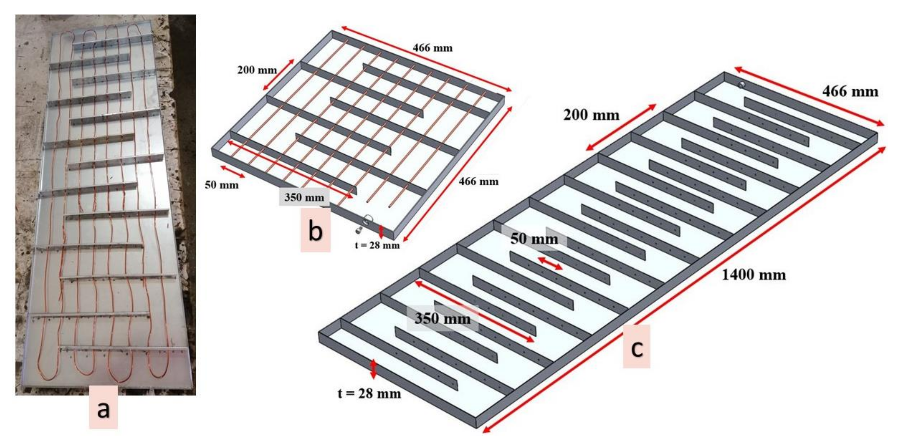
| Steel macrocontainers | 1400 × 466 × 28 mm3 | 9 | 60 | 540.0 |
| Copper wires | 2.5 mm diameter, 10 kg | 8 | 12 | 96.0 |
| Overall Cost ($) | 1916.0 | |||
| Item | Specifications | Quantity | Price/Item ($) | Total Cost ($) |
|---|---|---|---|---|
| Electric cable | - | 15 | 0.4 | 6.0 |
| Temperature controller | - | 1 | 33 | 33.0 |
| Hydronic pipes | PEX aluminum 18 | 40 | 0.65 | 26.0 |
| Holding clips | Clips 18 | 80 | 0.23 | 18.4 |
| Female cap | HE 1/2 in | 2 | 10.5 | 21.0 |
| Racor fittings | Brass (size 18 × 10) | 16 | 1.58 | 25.3 |
| Caps | Chrome 1/2 in | 18 | 0.9 | 16.2 |
| Male elbow 18 | Aluminum chrome 1/2 in | 4 | 2.65 | 10.6 |
| One way valve | SERA 1/2 in | 4 | 4.45 | 17.8 |
| T-connector | AFL 1/2 in | 2 | 1.65 | 3.3 |
| Boiler screws | - | 1 | 1.65 | 1.7 |
| Double Teflon | Large | 2 | 1.15 | 2.3 |
| PEX holding XPS plates | 1.4 × 1.4 m2 | 5 | 10 | 50.0 |
| Circulating pump | - | 2 | 50 | 100.0 |
| Electric relay | 220 v | 2 | 8 | 16.0 |
| Electric boiler | 50 L resistance | 1 | 68 | 68.0 |
| Overall Cost ($) | 415.6 | |||
Publisher’s Note: MDPI stays neutral with regard to jurisdictional claims in published maps and institutional affiliations. |
© 2022 by the authors. Licensee MDPI, Basel, Switzerland. This article is an open access article distributed under the terms and conditions of the Creative Commons Attribution (CC BY) license (https://creativecommons.org/licenses/by/4.0/).
Share and Cite
Faraj, K.; Khaled, M.; Faraj, J.; Hachem, F.; Castelain, C. A Summary Review on Experimental Studies for PCM Building Applications: Towards Advanced Modular Prototype. Energies 2022, 15, 1459. https://doi.org/10.3390/en15041459
Faraj K, Khaled M, Faraj J, Hachem F, Castelain C. A Summary Review on Experimental Studies for PCM Building Applications: Towards Advanced Modular Prototype. Energies. 2022; 15(4):1459. https://doi.org/10.3390/en15041459
Chicago/Turabian StyleFaraj, Khaireldin, Mahmoud Khaled, Jalal Faraj, Farouk Hachem, and Cathy Castelain. 2022. "A Summary Review on Experimental Studies for PCM Building Applications: Towards Advanced Modular Prototype" Energies 15, no. 4: 1459. https://doi.org/10.3390/en15041459
APA StyleFaraj, K., Khaled, M., Faraj, J., Hachem, F., & Castelain, C. (2022). A Summary Review on Experimental Studies for PCM Building Applications: Towards Advanced Modular Prototype. Energies, 15(4), 1459. https://doi.org/10.3390/en15041459