Article

Heat Transfer Analysis of a Co-Current Heat Exchanger with Two Rectangular Mini-Channels

1
Faculty of Mechatronics and Mechanical Engineering, Kielce University of Technology, 25-314 Kielce, Poland
2
Faculty of Management and Computer Modelling, Kielce University of Technology, 25-314 Kielce, Poland
*
Author to whom correspondence should be addressed.
Energies 2022, 15(4), 1340; https://doi.org/10.3390/en15041340
Submission received: 9 January 2022 / Revised: 2 February 2022 / Accepted: 9 February 2022 / Published: 12 February 2022

Abstract

:
This paper presents the results of research on heat transfer during fluid flow in a heat exchanger with two rectangular mini-channels. There was Fluorinert FC-72 flow, heated by the plate in the hot mini-channel, and co-current flow of distilled water in the cold mini-channel. Both fluids were separated by the copper plate. A thermal imaging camera was used to measure the temperature distribution of the outer surface of the heated plate. The purpose of the calculations was to determine the heat transfer coefficients at the contact surfaces: the heated plate—FC-72 and FC-72—the copper plate. Two mathematical models have been proposed to describe the heat flow. In the 1D approach, only the heat flow direction perpendicular to the fluid flow direction was assumed. In the 2D model, it was assumed that the temperature of the heated plate and FC-72 and the copper plate meet the appropriate energy equation, supplemented by the boundary conditions system. In this case, the Trefftz functions were used in numerical calculations. In the 1D model, the heat transfer coefficient at the interface between FC-72 and the copper plate was determined by theoretical correlations. The analysis of the results showed that the values and distributions of the heat transfer coefficient determined using both models were similar.

1. Introduction

Heat exchangers are currently used in all branches of industry in which heat transfer occurs. They are applied in the computer and IT industry for cooling integrated circuits, computer motherboards, server racks, etc. Recently, compact heat exchangers have also been looking for solutions to improve the work of renewable energy devices, such as PVT photovoltaic cells. The constant improvement and tightening of environmental protection requirements, as well as the growing efficiency of devices, contribute to the search for compact heat exchangers that would be increasingly energy efficient, effective and based on environmental-friendly fluids.
The desire to ensure high efficiency of heat exchangers is a part of the common trend towards miniaturization of heating and cooling technology devices. Studies of compact heat exchangers with small gaps of different geometries were described in [1]. The authors demonstrated that the micro-channel with geometry produced in the plane surface jet in comparison to the straight one may dissipate more heat. It was presented that the flux position influences the total performance of the heat exchanger and needs to be optimized for a specific condition and geometry.
The work [2] concerns experimental heat transfer data investigated on the plate heat exchanger dedicated for use in hydraulic cooling systems. The heat exchanger consisting of thin metal welded plates of stainless steel was tested. On the basis of the experimental data, a correlation was estimated for Nusselt number as a function of other dimensionless numbers, namely, Reynolds number and Prandtl number. In addition to convective and overall heat transfer coefficients, exchanger effectiveness was determined.
Heat transfer in the plate heat exchanger with modified surface was discussed in [3]. In the research, the corrugated plate heat exchanger (PHE) was tested as a commercial model. On the basis of the results of investigation of the water–ethanol system, it was noticed that the heat transfer coefficient on the ethanol side achieved higher values for the modified heat exchanger. Furthermore, on the water side, higher values of the coefficient were gained than on the commercial one.
The paper [4] describes the gasketed plate heat exchanger (GPHE) as a model commonly used in industries such as chemical processes and refrigeration. It is a type of heat exchanger that is used in condensation or evaporation systems. Due to the complex design of the corrugated surface, the fluid flow during its work should be highly turbulent.
The plate-fin heat exchanger (PFHE) is a type of compact heat exchanger that has a lot of applications such as vehicle radiators, air conditioners and gas liquefiers. In paper [5], the three following types of nanofluid were applied as working fluids flowing through a PFHE: SiO2, TiO2 and Al2O3. The authors tested applying the nanofluids in a heat exchanger to influence the heat transfer rate. The effects on the thermophysical properties and heat transfer characteristics were realized in comparison to those obtained for the base fluid. The results showed that the thermal conductivity and the heat transfer coefficient increased with the addition of nanoparticles and TiO2.
Today, there is increasing attention to heat exchangers with mini- or micro-channels. Numerous articles have been published concerning heat transfer during flow in mini-channel test sections. A literature review on the investigation of flow boiling heat transfer in micro-scale channels, including physical mechanisms, models and correlations, was presented in [6].
The paper [7] presents mini-channel heat exchangers that were applied in small-scale organic Rankine cycle (ORC) installations. The authors have shown four 1-dimensional models of the wall thermal resistance in heat exchangers with rectangular mini-channels. The first model was with a single wall that separated two fluids. In the second model, the total volume of intermediate walls between layers of mini-channels and their side walls were taken into account. Two other models assumed the thermal resistance of the mini-channel walls. After analyzing the models, it was indicated that the thermal resistance of the metal walls could be neglected. Moreover, models show that the optimal wall thickness is relatively small taking into account plastic walls.
In the study [8], the authors focused on the boiling of deionized water during flow in a horizontally oriented rectangular mini-channel. Six types of flow patterns were noticed. An amendment correlation for the heat transfer coefficient was also proposed.
In [9], the effect of channel size on the temperature field of the battery modules was tested. Inlet boundary conditions were also taken into account in the analysis. The channel width of the cooling plates was found to be highly influential on the temperature of the battery module. Compared to the other designed channel, the advantages of low manufacturing cost and low flow resistance of the rectangular flow with the straight-shaped channels were underlined.
Researchers are examining different cross-sections of mini-channels, because geometries have a strong influence on the flow characteristics. In the works [10,11,12], the problem of boiling heat transfer during flow in an annular mini-gap was investigated. Boiling heat transfer in a small circular and a small rectangular channel with refrigerant, R-12 was explored in [13]. The effects of channel geometry and fluid properties on heat transfer were presented. Furthermore, heat transfer mechanisms in small channels were analyzed. The results were compared with the correlations of other authors. In numerical simulations for the heat transfer process, commercial software is often used, such as ANSYS CFX/Fluid [14], ADINA [15] and Simcenter STAR-CCM+ Software [16].
In the paper, a number of well-known heat transfer correlations were used. There are many correlations in the available literature that describe flow boiling in conventional and small diameter channels. Analysis of the correlations of boiling heat transfer was presented in [17]. Dutkowski correlation concerns flow boiling heat transfer of R-134a, R-404a in channels with a diameter of 2.30 mm, circular mini-channels. According to this correlation, the Nusselt number is a function of two dimensionless numbers: the Reynolds number and the boiling number. Cooper correlation was proposed mainly for the description of pool boiling heat transfer [18]. Mikielewicz correlation is a modification of Dittus-Boelter correlation by introducing the vapour quality. The most commonly used correlation to determine the heat transfer coefficient for a fully developed turbulent flow in smooth tubes is the Dittus–Boelter correlation [19]. Mikielewicz correlation [20] was dedicated to determine the heat transfer coefficient in, both subcooled and saturated boiling regions.
Previous studies conducted by the authors focused on heat transfer investigations, based on experimental data collected during fluid flow in the test section comprising: a singular mini-channel or a group of mini-channels of rectangular cross section [17,21,22] and with an annular mini-gap [10,12] Experiments covered single-phase forced convection, subcooled and saturated boiling regions during one medium flow in the channel system. Furthermore, mathematical models of heat transfer in the test sections and solution were proposed using methods based on the Trefftz functions helped by the FEM [22] and the hybrid Picard–Trefftz method [23] for time-dependent and stationary conditions. A model for subcooled flow boiling in mini-channels and numerical computations were performed using two commercial programs: ADINA [15] and Simens Simcenter STAR-CCM+ software [16]. Until now, the typical heat exchanger test section with two different working fluids flowing in two additional mini-channels has not been used for testing in the research setup.
In general, the main novelties of this work cover are:
  • Testing a new construction of a mini heat exchanger, which required essential changes compared to previous constructions;
  • The proposition of a mathematical model to describe heat transfer in a mini heat exchanger with two channels, fixed on the mini-channel with hot fluid flow.
In this paper, two-dimensional mathematical models of a co-current heat exchanger with two rectangular mini-channels are described. Solving the proposed system of energy equations with the appropriate set of boundary conditions leads to the solution of inverse identification problems. The parameters to be identified include the temperature of selected elements in the measuring section, temperature gradients at their boundaries and heat transfer coefficients between the working fluid and the walls of the channel with the flowing fluid. Solutions of inverse problems in engineering are highly sensitive to input data uncertainties and have troublesome ill-posedness. This sensitivity intensifies when three consecutive inverse problems are considered. Even advanced commercial software can fail in such cases. Thus, stable methods are necessary to solve inverse problems in engineering, including conjugate inverse problems. The Trefftz method [24] meets the requirements mentioned above as confirmed by the results shown in [25,26]. An extensive review of research devoted to solving inverse heat transfer problems in mini-channels using methods based on Trefftz functions, called T-functions for short, is presented in [23]. In the two-dimensional approach discussed in this paper, the Trefftz method allowed determining the temperature distribution in selected elements of the measuring section in the form of continuous and differentiable functions that exactly satisfy the relevant differential equations. Two sets of Trefftz functions were used: Trefftz functions specific to energy equation in fluids and harmonic functions [25]. The results of the calculation based on the experimental data were compared with the one-dimensional approach that used correlations derived from the literature, and the comparison results were consistent.

2. Experiment

2.1. Experimental Stand and Test Section

The experimental setup is shown in Figure 1. Its main elements are: the test section with two mini-channels (1), circulating pumps (2,8), pressure meters (3), heat exchangers (4a,4b), filters (5,9), mass flow meter (6a), magnetic mass flow meter (6b), air separators (7,10), an ammeter (11), a voltmeter (12) and an infrared camera (13). The most important circuits realized on the experimental setup are two closed loops of the working fluids, including: one named the hot fluid circuit, in which the working fluid FC-72 circulates, and the other named the cold fluid circuit, in which distilled water flows. A data acquisition station (14), PC computer (15), and a power supply (16) complement the experimental stand equipment.
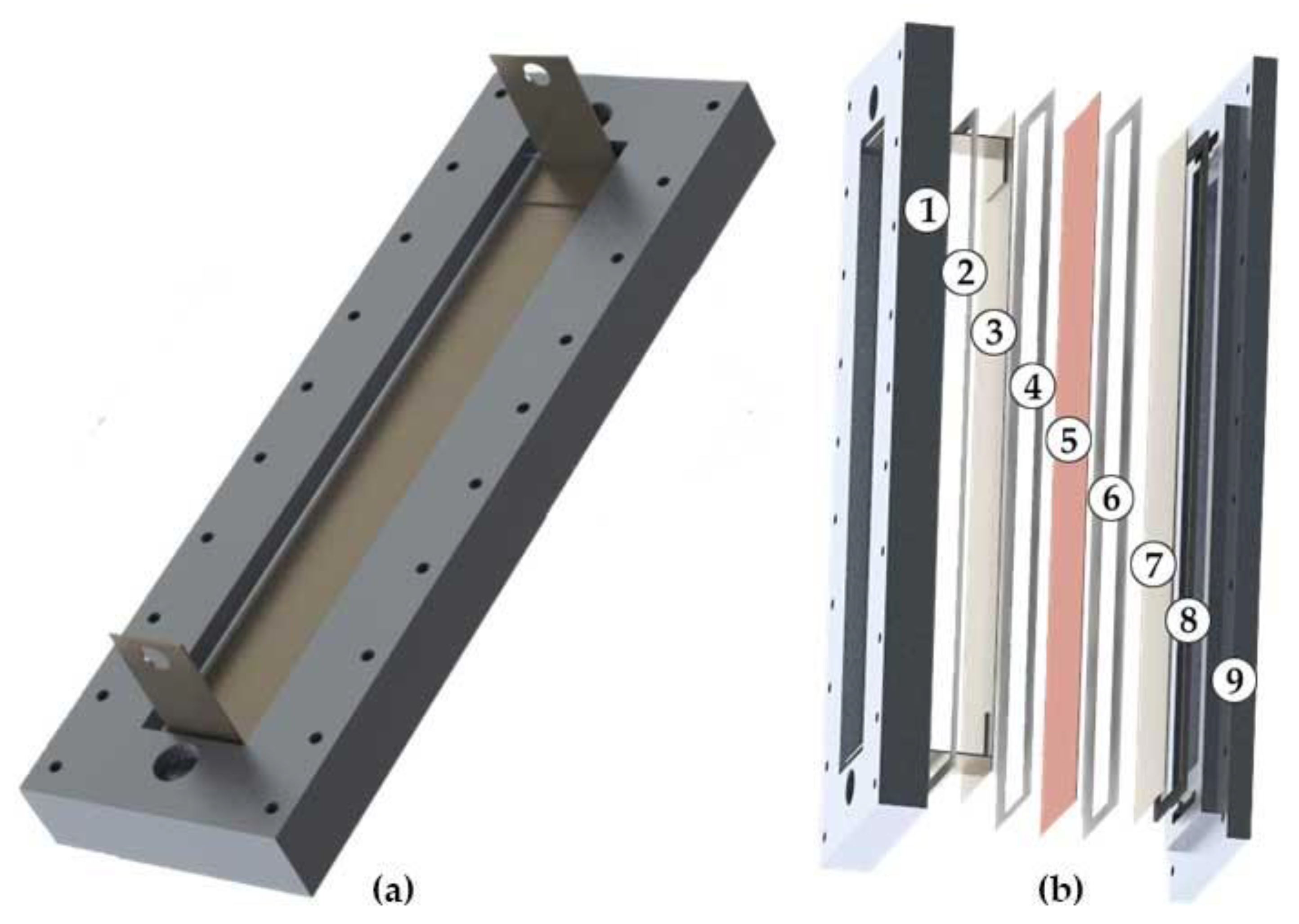
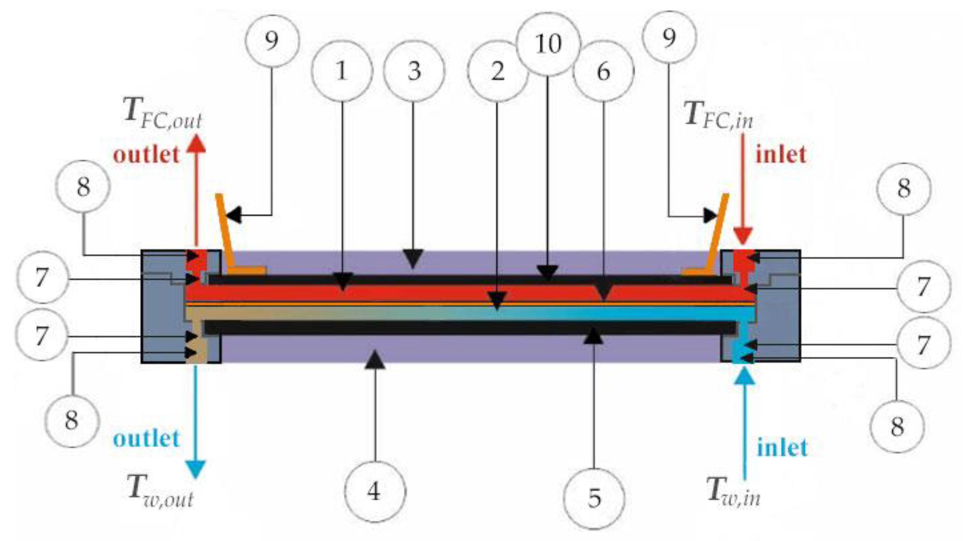
The 3D view of the test section with mini-channels is shown in Figure 2a whereas the individual components of the test section are presented in Figure 2b. Its most important elements are three parallel plates, constituting the main walls of two mini-channels of a rectangular cross-section (each 1.5 mm deep, 24 mm wide and 240 mm long), Figure 3. Additional elements of the module are silicone gaskets. Through the mini-channels, separated by a copper plate, there is flow of FC-72 fluid in the hot mini-channel and distilled water in the cold mini-channel. The outer wall (10) of the hot mini-channel (1) is resistively heated. It is a thin plate (thickness δH = 0.45 mm) made of the Haynes-230 alloy. The electrodes made of Hastelloy X alloy (9) are connected to the power supply system. The thermal imaging camera is used to measure the temperature of the outer surface of the heated plate [27]. Heat transfer between co-current flowing media occurs through a copper plate (6) with a thickness of 0.3 mm. The outer wall of the cold mini-channel is a plate (5) with a thickness of 0.45 mm, also made of Haynes-230 alloy. K-type thermocouples and pressure gauges have been installed at the inlet and outlet of the collectors that supply each mini-channel.

2.2. Experimental Procedure, Parameters and Errors

After deration of the flow circuit installation and the test section, as well as stabilizing the pressure and flow rate of the fluids, the heat flux supplied to the heated plate is gradually increased by fluid adjustment of the current. The co-current flow of working fluids in mini-channels is forced by the operation of pumps. A thermal imaging camera is used to monitor the temperature of the outer heated plate surface.
The main parameters and errors of the experiments are listed in Table 1.

3. The Methods of Heat Transfer Coefficient Determination

3.1. General Assumptions

Local heat transfer coefficients between the FC-72 working fluid and the two channel walls (the Haynes-230 alloy heated plate and the copper plate) were determined assuming the following:
  • steady state in the test section and temperature independence of the physical parameters of the test section’s elements,
  • negligible heat losses to the environment through the external surfaces of the test section; the system is insulated,
  • convective heat transfer in the mini-channels,
  • the parallel flow of the fluids from both sides of the copper plate,
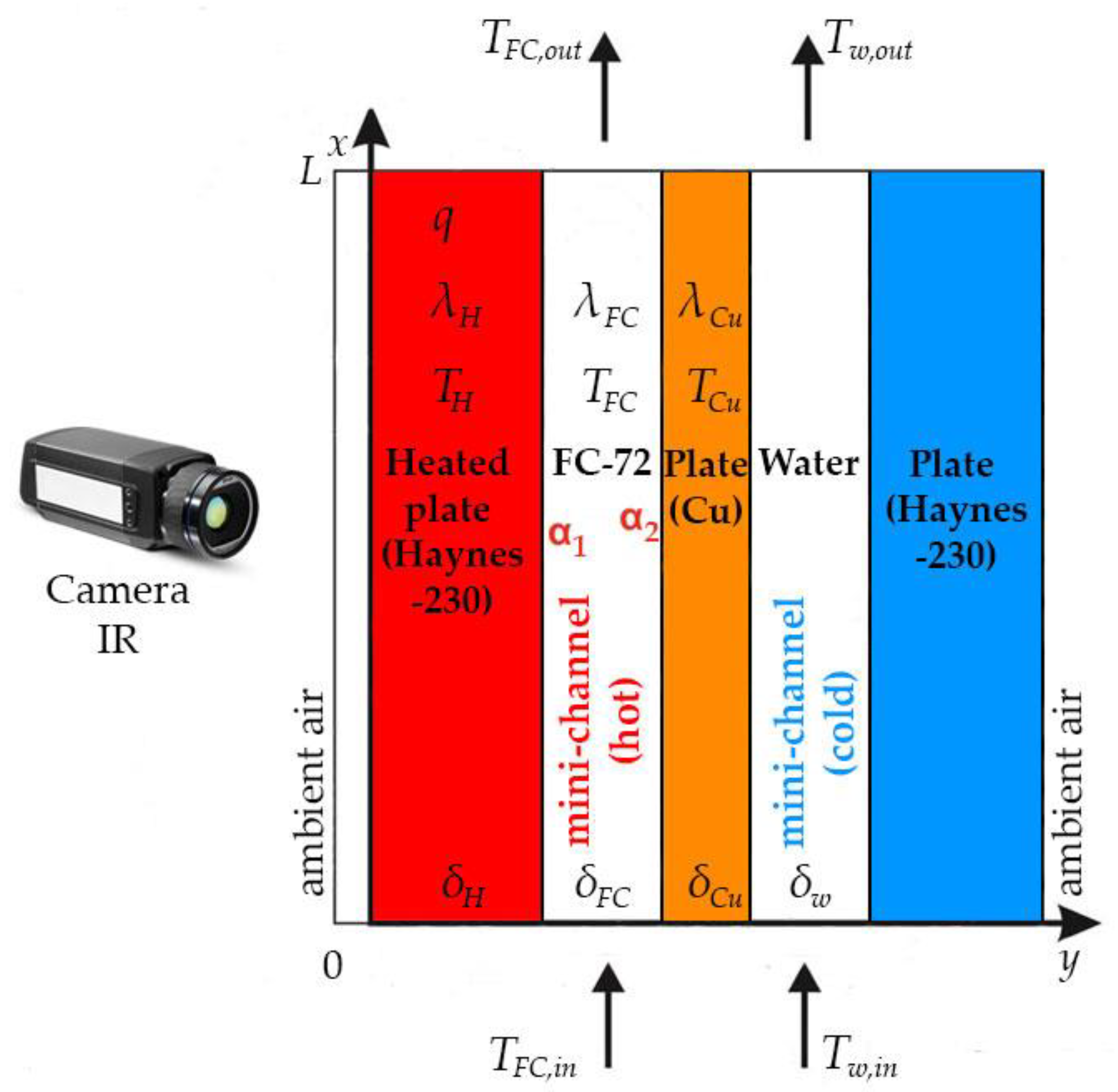
  • the laminar flow of both fluids with a constant mass flow rate and known temperatures at the inlets and outlets of the mini-channels, Figure 3 and Figure 4.

3.2. Two-Dimensional Approach

Two dimensions are included in the 2D model of heat transfer in the test section: dimension x parallel to the flow direction and dimension y perpendicular to the flow direction representing the plate thicknesses and channel depths. It is assumed that the temperatures of the heated plate TH, the hot fluid TFC and the copper plate TCu satisfy the adequate differential equations, that is:
for   the   heated   plate :             2 T H = q λ H δ H = I Δ U A   λ H δ H
for   fluid   FC - 72 :       2 T FC = c p , FC   ρ FC λ FC · T FC x · w FC ( y )
for   the   copper   plate :               2 T Cu = 0
For the Poisson’s Equation (1), the temperature of the insulated outer wall is assumed to be known from thermal camera measurements and that both walls perpendicular to it are insulated. With these assumptions, the boundary conditions for Equation (1) can take the form:
T H ( x , 0 ) = T H , IR ( x )  
( a )   T H ( x , 0 ) y = 0 ,   ( b ) T H ( 0 , y ) x = 0 ,   ( c )   T H ( L , y ) x = 0
For Equation (2), the assumptions are as follows:
-
the parabolic velocity w FC ( y ) is parallel to the heated plate and is satisfying the following condition:
1 δ FC δ H δ H + δ FC w FC ( y ) dy = w ave
-
the temperature of the FC-72 fluid (flowing in the hot mini-channel) at the contact area with the heated plate at the mini-channel inlet and outlet is known, i.e.,:
T FC ( x , δ H ) = T H ( x , δ H )
( a )   T FC ( 0 , y ) = T FC , in ,   ( b )   T FC ( L , y ) = T FC , out
For Laplace Equation (3), adequate boundary conditions are adopted, that is, fluid FC-72 and the copper plate are in perfect thermal contact and the walls perpendicular to them are insulated as follows:
T Cu ( x , δ H + δ FC ) = T FC ( x , δ H + δ FC )
λ C u T C u ( x , δ H + δ FC ) y = λ FC T FC ( x , δ H + δ FC ) y
  ( a )   T Cu ( 0 , y ) x = 0 ,   ( b )   T Cu ( L , y ) x = 0
Additionally, at the perpendicular walls the temperature TCu satisfies the conditions:
  ( a ) T C u ( 0 , y ) = max ( T FC , in , T w , in ) ,   ( b )   T Cu ( L , y ) = max ( T FC , out , T w , out )
Solving Equations (1)–(3) with boundary conditions (4)–(12) leads to the solution of three consecutive inverse heat transfer problems within three adjacent areas (the heated plate, FC-72 fluid, the copper plate) that differ in size and physical parameters. Inverse problems are ill-posed problems [29] that require stable and effective solving methods. This requirement is met by the Trefftz method [24] in which the unknown solution of a partial linear differential equation is approximated by a linear combination of functions (called Trefftz functions or T-functions) that exactly satisfy this equation. In this study, sets of Trefftz functions were used in this study: harmonic functions for the Laplace’s and T-functions specific to energy equation in fluids [25,26]. Two-dimensional temperature distributions are determined as in [26]. The known two-dimensional temperature distributions of: the heated plate TH, the fluid TFC and the copper plate TCu allow determining the values of corresponding local heat transfer coefficients at the boundaries between the FC-72 fluid and the heated plate ( α 1 ,   2 D (x)) and FC-72 fluid and the copper plate ( α 2 ,   2 D (x)) from the following formulas:
the   heated   plate FC - 72   fluid :   α 1 , 2 D ( x ) = λ H T H y T H ( x , δ H ) T FC , r e f ( x )  
FC - 72   fluid the   copper   plate :   α 2 , 2 D ( x ) = λ C u T C u y T C u ( x , δ H + δ FC ) T FC , ref ( x )
In Equations (13) and (14), the reference temperature of FC-72 is calculated as in [30]:
T FC , ref ( x ) = 1 δ FC δ H δ H + δ FC T FC ( x , y ) dy

3.3. One-Dimensional Approach

The results obtained from the 2D approach were verified with the proposed simplified 1D model which included only the dimension perpendicular to the flow. The assumption about the insulation of the test section allows assuming that the entire volumetric heat flux generated inside the heated plate is transferred to the flowing fluid FC-72 according to Fourier’s law:
λ H T H ( x ,   δ H ) y =   q = I Δ U A
Since the heated plate is very thin ( δ H   = 4.5 · 10 4   m ), the temperature of the heater plate T H ( x ,   δ H ) is calculated by replacing the partial derivative T H ( x ,   δ H ) y in Equation (16) with the difference quotient. Therefore, by adjusting formula (13) to the one-dimensional model, the heat transfer coefficient in the contact area between the heated plate and the fluid FC-72 has the form [27]:
α 1 , 1 D ( x ) = q λ H λ H ( T H , IR ( x ) T FC , lin ( x ) )   q δ H  
where temperature of the hot fluid (FC-72) T FC , lin ( x ) is calculated from:
T FC , lin ( x ) = T FC , out     T FC , in L ·   x + T FC , in  
Then, the heat transfer coefficient α 2 , 1 D ( x ) at the interface between the FC-72 and the copper plate is determined using selected theoretical correlations known from the literature, Table 2.
Table 2. Heat transfer correlations selected from the literature.
AuthorEquationRemarks
Cooper [18]
α PB = 55   p r 0.12     0.2   logRp   ·   ( logp r ) 0.55   ·   M l 0.5   ·   q 0.67
-
Pool boiling
-
Used as the component of correlations for flow boiling heat transfer
Mikielewicz [20]
α PB α D B = 120 · Ku 0.7 · Ja 0.6
where:
α PB —heat transfer coefficient calculated from Equation (19)
α DB —heat transfer coefficient determined from Dittus–Boelter Equation [19]:
α DB = 0.023   ·   Re l 0.8   ·   Pr l 0.4   ·   λ l d h
-
Flow boiling
-
The subcooled boiling region
-
For conventional channels
Dutkowski [17]
α TP = 0.41 · Re l 0.848 · Bo 0.66 · Co 0.62 · ( ρ l ρ v ) 1.28
-
Flow boiling
-
The saturated boiling region
-
For circulated mini-channels

4. Results and Discussion

Calculations were made for the heat flux density q from the range 12.26 ÷ 33.93 kW/m2. The values of the remaining experimental thermal and flow parameters are given in Table 3.
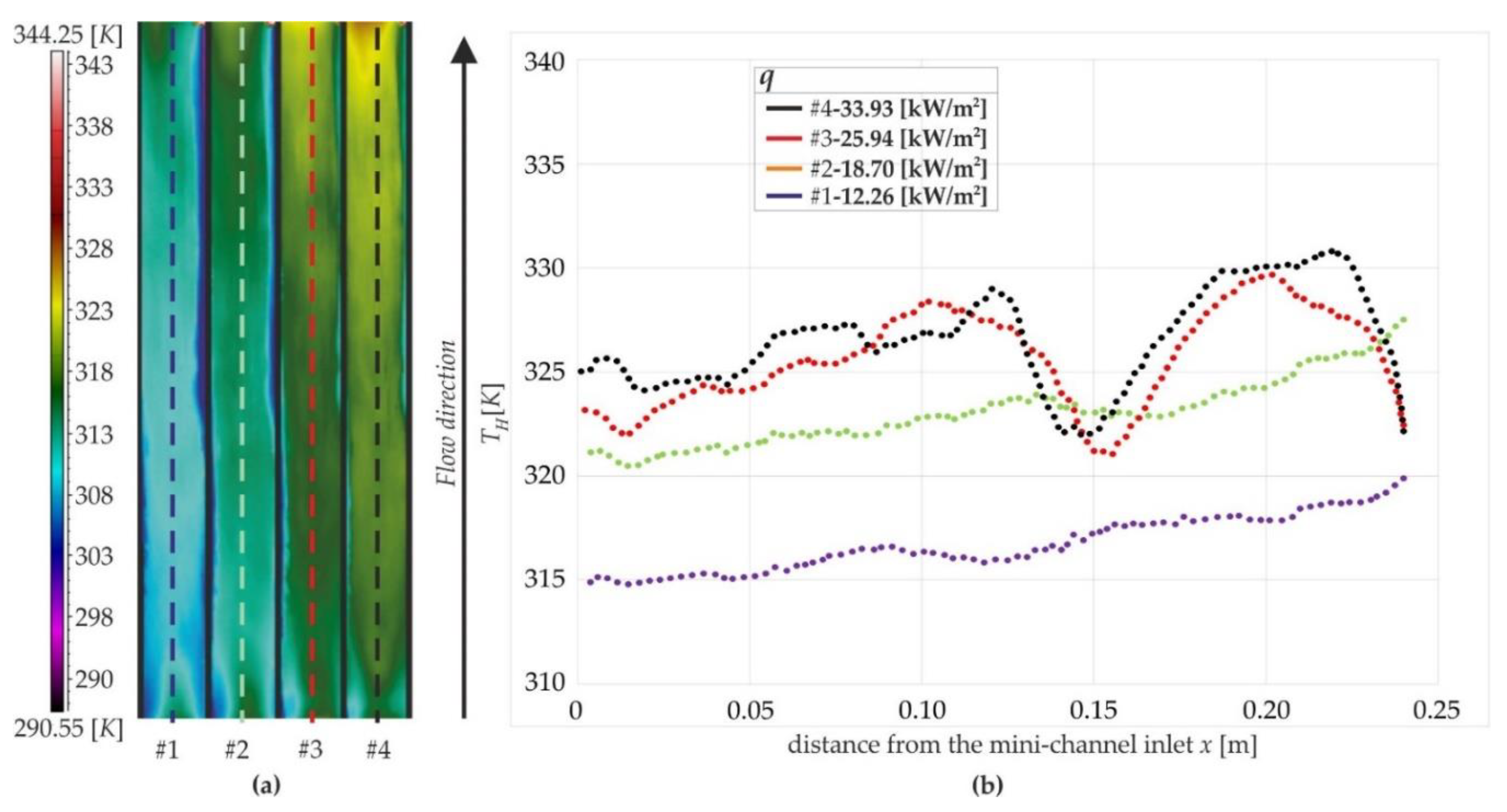
Figure 5a shows the thermograms recorded with the thermal camera, corresponding to the temperature distributions on the outer heated plate surface. Calculations were made for the central cross section of the mini-channel along its length, where the heated plate temperature changes as shown in Figure 5b.
When designing heat exchangers, it is important to determine the overall heat transfer coefficient and the Fanning friction factor. For the co-current heat exchanger, the overall heat transfer coefficient related to the heat transfer area A was calculated as follows:
k = Q A Δ T
where Δ T means log mean temperature difference calculated as in [31] and Q is the average of the heat fluxes from the hot and cold mini- channels.
The Fanning friction factor was obtained using the following formula, [32,33]:
f Re = 24 ( 1     1.3553 K + 1.9467 K 2   1.7012 K 3 + 0.9564 K 4   0.2537 K 5 )
where K is the channel aspect ratio equal to the ratio of the channel width to the channel depth.
The value of the overall heat transfer coefficient, the Fanning friction factor and average values of selected dimensionless numbers, mainly Reynolds, Prandtl and Graetz numbers, determined for both mini-channels and each supplied heat flux, are given in Table 4. Reynolds number values indicate laminar fluid flow in both mini-channels.
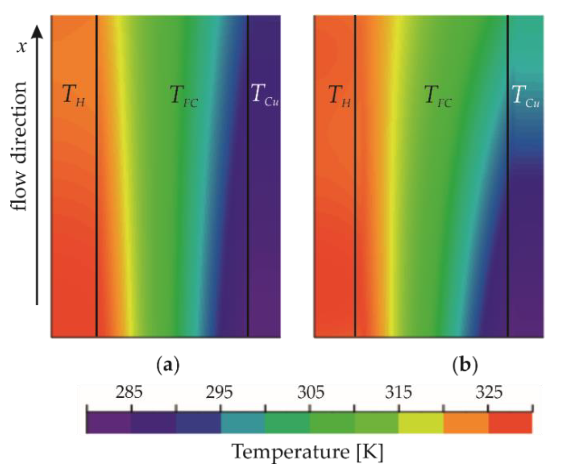
In the 2D approach with the Trefftz method, the temperature distribution was first determined for the heated plate, then for the FC-72 fluid, and finally for the copper plate. The basic properties of the functions obtained in this way are given in [23,25]. Figure 6 shows the two-dimensional temperature distribution of the three areas: the heated plate, the flowing fluid FC-72 and the copper plate.
It can be noticed that the FC-72 fluid entering the cold mini-channel is heated by the Haynes-230 alloy plate mainly at the contact surface. The liquid next to the heated wall has a strongly increased temperature, which decreases significantly with distance from it. In the hot mini-channel axis, there is a moderate temperature of the fluid which decreases as the cold channel approaches (see Figure 6a for lower value of heat flux). Based on data, it is obvious that in the hot channel, heat transfer proceeds by a single-phase forced convection starting from the channel inlet up to the middle along the FC-72 flow; then, the single-phase region is transferred to the subcooled boiling region near the channel outlet. Heat transfer is probably not greatly disturbed by the increase in the amount of bubbles in the flowing vapour-liquid mixture. The resulting heat transfer coefficient at the heated plate–fluid FC-72 interface reached values on the order of several hundred to a maximum above two thousand W/(m2K), increasing along the channel length, Figure 7. It confirms the authors’ previously obtained results concerning asymmetrically heated mini-channels with the flow of one fluid [15,23]. At the same time, cold water flowing in the second channel cools the copper plate and is, however, in the case of a higher heat flux, less intense (see Figure 6b). In the cold channel, the differences between the plates temperature and water temperature are small and single phase convection occurs in the entire mini-channel.
When analyzing the dependences illustrated in Figure 7, it is observed that the values of the heat transfer coefficient α1 increase with increasing heat flux, reaching maximum:
-
α1,1D = 2.22 kW/(m2K)—Figure 7a, results of the 1D approach,
-
α1,2D = 2.36 kW/(m2K)—Figure 7b, results of the 2D approach.
For both approaches, the calculation results are similar, with higher heat transfer coefficients obtained from the 2D approach (Figure 7b) compared to the corresponding based on the 1D approach (Figure 6a).
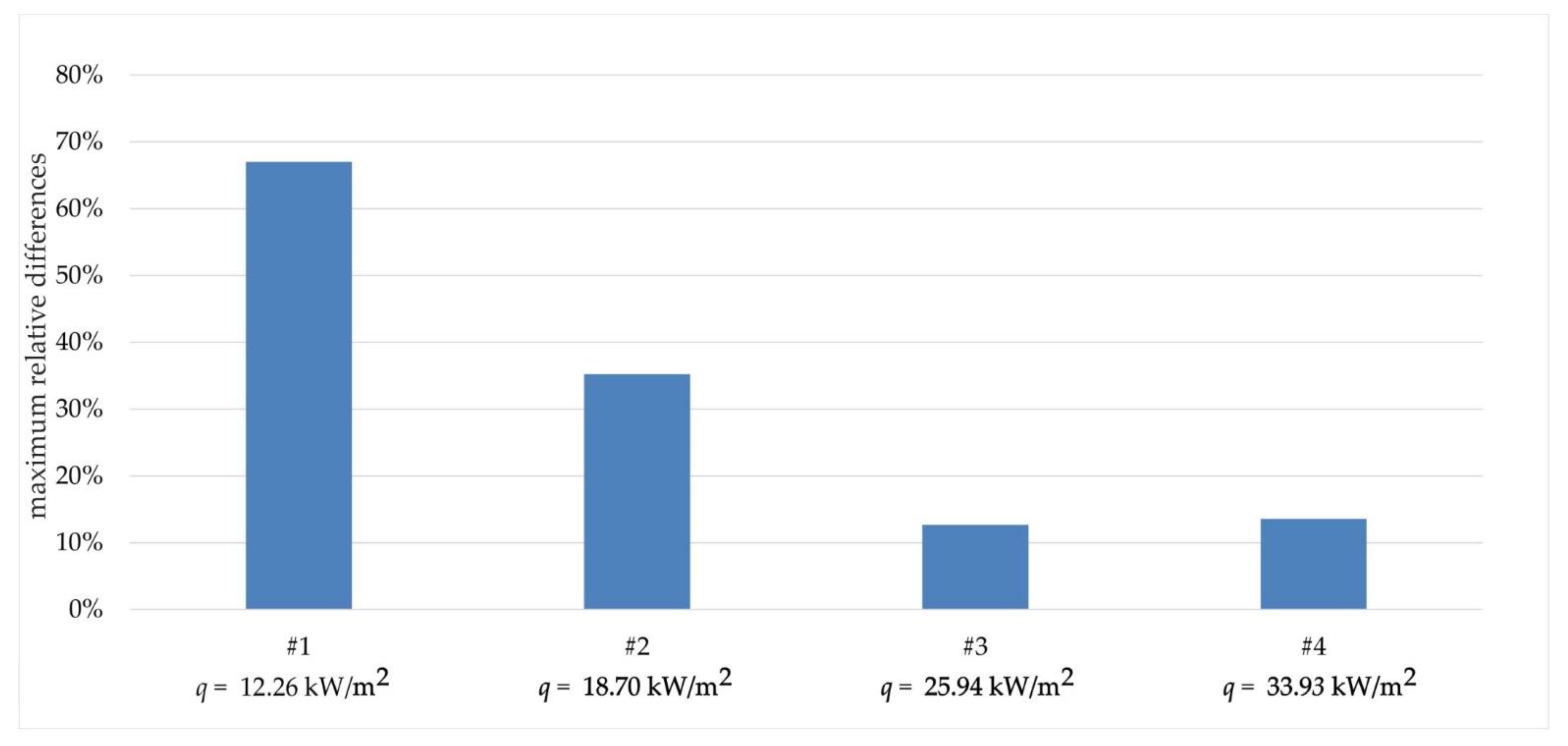
The values of the maximum relative differences for the heat transfer coefficients obtained with the two approaches (Equations (13) and (17)) and calculated as in [26] does not exceed 67% and decreases with increasing heat flux, Figure 8.
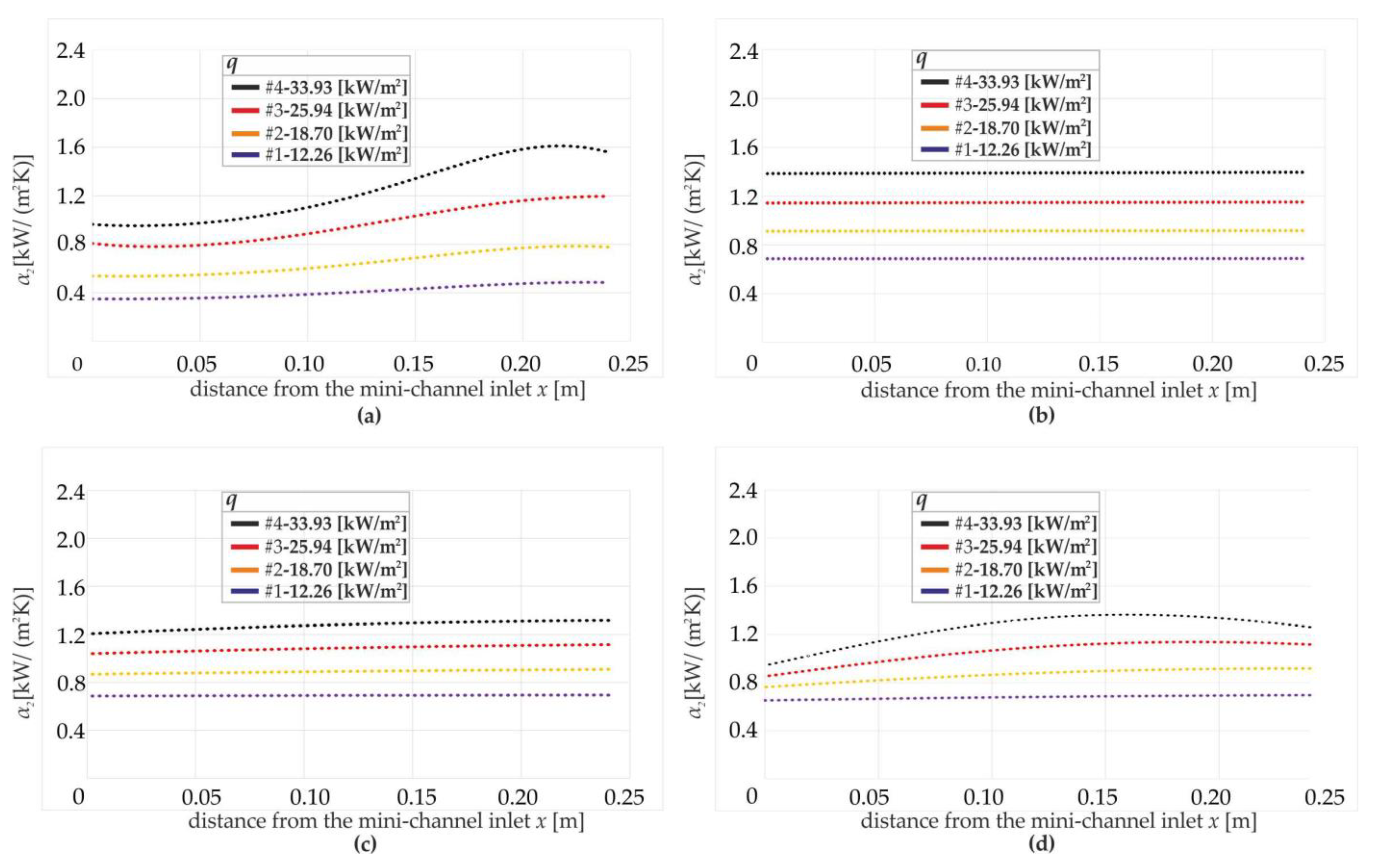
The values of the heat transfer coefficient α2 at the interface between FC-72 and the copper plate are shown in Figure 9. Figure 9a shows the variability of the heat transfer coefficient calculated by the Trefftz method, while Figure 9b–d show the coefficient values calculated based on the correlations given in Table 2. For the same experimental data, the α2 values are lower than those of α1, see Figure 7 and Figure 9. As in the case of the heat transfer coefficient α1, the values of α2 increase with increasing distance from the channel inlet and the heat flux supplied to the heated plate.
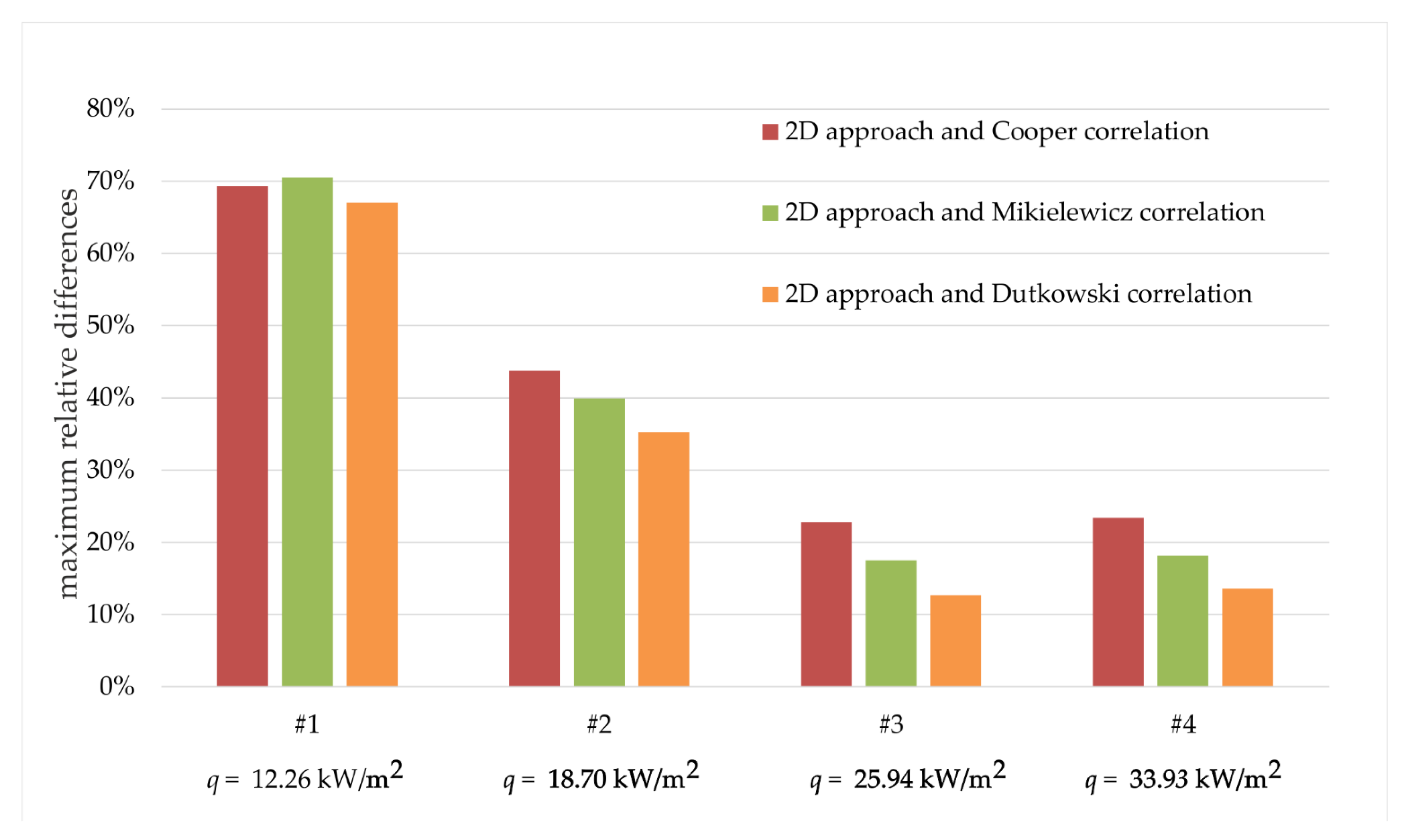
Heat transfer coefficients α2 at the FC-72–copper plate contact surface were calculated according to the 2D approach—Equation (14), Cooper correlation—Equation (19), Mikielewicz correlation—Equation (20) and Dutkowski correlation—Equation (22). The results are shown versus the distance from the mini-channel inlet in Figure 9a–d, respectively. The coefficients determined according to Dutkowski correlation show good agreement with the experimental results. The maximum relative differences, between the heat transfer coefficient calculated from Equation (14) and the heat transfer coefficients obtained from the correlations listed in Table 2, range from 12.69% (for q = 25.94 kW/m2) to 70.5% (for q = 12.26 kW/m2), Figure 10.
Analyzing the results shown in Figure 10 that illustrate the comparative results according to the 2D approach and obtained using selected correlations from the literature, the values of the maximum relative differences were lower for higher heat fluxes. The highest was reached, up to 70.5%, for q = 12.26 kW/m2 when the Mikielewicz correlation was tested. The trend of decreasing the maximum relative differences with increasing heat flux supplied to the heated plate was detected, although the smallest values were obtained for q = 25.94 kW/m2 (not the smallest heat flux value). Furthermore, it was observed that the smallest values of relative differences for each heat flux were achieved when the Dutkowski correlation was used in comparative analyses. The smallest relative differences equal to 12.69% were observed for q = 25.94 kW/m2 when the Dutkowski correlation was applied in the calculation.
For the 2D approach, the mean relative error of the heat transfer coefficient was calculated as in [34] while the uncertainties of the measurements were taken from Table 2. Analogically, the mean relative errors of the heat transfer coefficient were calculated for the 1D approach. Table 5 compares the mean relative errors of the heat transfer coefficients in both mathematical approaches.
The values of the mean relative errors occurred as smaller while the one-dimensional approach was used in comparison to the 2D approach. For both calculation methods, the mean relative errors decrease with increasing heat flux supplied to the heated plate and reach the highest value of 14.7% for q = 12.26 kW/m2 in the 2D approach.
Figure 11 presents the values of the heat transfer coefficient together with error bars in the case where the highest value of the mean relative error was obtained, i.e., when q = 12.26 kW/m2. For the 1D approach, the errors are evenly distributed along the entire length of the mini-channel.
In contrast, for the 2D approach, the errors increase with the distance from the inlet to the mini-channel, achieving the highest values at the outlet of the mini-channel.

5. Conclusions

The paper discusses the results of tests related to heat transfer during two fluid flows in two rectangular mini-channels separated by a copper plate while the test section was oriented vertically. Heat flux was supplied to the outer surface of the hot mini-channel wall in which there was a Fluorinert FC-72 flow. The co-current flow of distilled water occurred in the cold mini-channel. The objective of the calculations was to determine the heat transfer coefficients characterizing the transfer of heat from the heated plate to the FC-72 fluid and from the FC-72 fluid to the copper plate. Two approaches were proposed that describe the heat flow in the test section: one-dimensional (1D) and two-dimensional (2D) for which Trefftz functions were used in calculations.
Based on the results of the experiments and their analysis, the following conclusions can be drawn:
  • In the hot mini-channel, heat transfer was transferred by single-phase convection and subcooled boiling occurs near the channel outlet; the heat transfer coefficients determined for both contact surfaces, that is, the Haynes-230 plate–the fluid FC-72 (α1) and the copper plate–FC-72 (α2) increased with increasing heat flux regardless of the calculation method chosen;
  • In the cold mini-channel, the temperature differences between plates and distilled water were low, as single-phase convection occurs in the entire mini-channel;
  • The resulting heat transfer coefficient at the heated plate–fluid FC-72 interface α1 reached values on the order of several hundred to a maximum of more than two thousand W/(m2K);
  • For the same experimental data, the α2 values are lower than those of α1;
  • For both mathematical approaches, the calculation results are similar, with higher heat transfer coefficients from the 2D approach compared with the corresponding coefficients from the 1D approach;
  • For the heat transfer coefficients on the heated plate–FC-72 contact surface (α1), the maximum relative differences between the results obtained from the two approaches (1D and 2D) decrease with increasing heat flux and do not exceed 67%;
  • For the heat transfer coefficient on the FC-72–cooper plate contact surface (α2), the maximum relative differences between the results (obtained from the 2D approach and the selected correlations) decrease with increasing heat flux supplied to the heated plate; good agreement with the experimental results showed those determined from Dutkowski correlation: the smallest relative differences equal to 12.69% were obtained for q = 25.94 kW/m2.
  • The values of the mean relative errors are smaller for the 1D approach compared to the 2D method and, for both calculation methods, decrease with increasing heat flux supplied to the heated plate reaching the highest value of 14.7% for q = 12.26 kW/m2. For the 1D approach, the mean relative errors are evenly distributed along the entire length of the mini-channel, while for the 2D approach, they increase with the distance from the inlet to the mini-channel.
Further research will address modification of the test section in order to provide temperature measurements from the plate separating the channels and to calculate heat transfer coefficients regarding the cold mini-channel, as well as testing heat transfer during counter-current flows in mini-channels. The main interest will be focused not only on the subcooled boiling region but also on the saturated boiling region, taking into consideration fluid flow in the hot mini-channel. In future investigations, enhanced surfaces of the plates will be used to verify whether their use can intensify heat transfer processes. Different materials of plates will be tested. In experiments, several working fluids of various physical properties will be applied. Further studies will also include modification of the mathematical model and application of the Picard–Trefftz hybrid method.

Author Contributions

Conceptualization, M.P., S.H. and D.S.; Data curation, A.P. and D.S.; Formal analysis, M.P., S.H., A.P. and D.S.; Funding acquisition, M.P.; Investigation, D.S.; Methodology, M.P., S.H., A.P. and D.S.; Project administration, M.P.; Software, S.H., A.P. and D.S.; Supervision, M.P., S.H. and A.P.; Validation, M.P., S.H., A.P. and D.S.; Visualization, S.H. and D.S.; Writing—original draft, M.P., S.H., A.P. and D.S.; Writing—review & editing, M.P., S.H., A.P. and D.S. All authors have read and agreed to the published version of the manuscript.

Funding

This research was funded by the National Science Centre, Poland, grant number UMO2018/31/B/ST8/01199.

Institutional Review Board Statement

Not applicable.

Informed Consent Statement

Not applicable.

Data Availability Statement

Data sharing not applicable.

Acknowledgments

The research reported herein was supported by a grant from the National Science Centre, Poland, No. UMO-2018/31/B/ST8/01199.

Conflicts of Interest

The authors declare no conflict of interest.

Nomenclature

Asurface area, m2
cpspecific heat, J/(kgK)
ddiameter, m
fFanning friction factor
Gmass flux, kg/(m2s)
hlvlatent heat of vaporization, J/kg
Icurrent, A
Kchannel aspect ratio
koveral heat transfer coefficient, W/(m2 K)
Llength of the mini-channel, m
Mmolecular weight, kg/mol
ppressure, Pa
Qheat flux, W
Qmmass flow rate, kg/s
qheat flux density, W/m2
Rproughness parameter, μm
Ttemperature, K
Δ T log mean temperature difference, K
ΔUvoltage drop, V
wvelocity, m/s
xcoordinate in the direction of flow, m
ycoordinate in the direction perpendicular to the flow and width of the partitions, m
2 = 2 x 2 + 2 y Laplacian in Cartesian coordinates
Greek Letters
αheat transfer coefficient, W/(m2K)
Δdifference,
δthickness, depth, m
λthermal conductivity, W/(mK)
µdynamic viscosity, Pa∙s
ρdensity, kg/m3
σsurface tension, N/m
Dimensionless Numbers
Bo = q Gh lv boiling number
C o = 1 d h   σ g   ( ρ l ρ v ) confinement number
Gz = RePr d h L Graetz numer
Ja = c pl · ρ l · Δ T sat h lv · ρ v Jakobe number
Ku = q h lv · ρ l · w   Kutateladze number
P r = μ l c p , l λ l Prandtl number
Re = Gd h μ l Reynolds number
Subscripts
aveaverage
Cucopper plate
DBrefers to Dittus–Boelter correlation
FCFC-72 fluid
Hheated plate
hhydraulic
inat the inlet
IRthermal imaging camera
lliquid
linlinear function
outat the outlet
PBpool boiling
rreduced (pressure)
refreference
satsaturation
TPtwo phase flow boiling
vvapour
wwater
1contact surface: Haynes-230 plate—FC-72 fluid
2contact surface: FC-72 fluid—copper plate
1Done-dimensional approach
2Dtwo-dimensional approach

References

  1. Bari, F.; Morshed, A.K.M.M. Ultra compact Heat Exchanger with geometry induced wall jet. Procedia Eng. 2015, 105, 258–263. [Google Scholar] [CrossRef] [Green Version]
  2. Anusha, G.; Kishore, P.S. Heat Transfer Analysis of Gasketed Plate Heat Exchanger. Int. J. Technol. Res. Eng. 2016, 5, 943–947. [Google Scholar] [CrossRef]
  3. Wajs, J.; Mikielewicz, D. Influence of metallic porous microlayer on pressure drop and heat transfer of stainless steel plate heat exchanger. Appl. Therm. Eng. 2016, 93, 1337–1346. [Google Scholar] [CrossRef] [Green Version]
  4. Rahul; Kumar, N.; Sehrawat, V.; Gupta, T.; Manju, R.; Iqbal Ahmad, M. Design Analysis of Gasketed Plate Heat Exchanger. Int. J. Technol. Res. Eng. 2017, 4, 1682–1685. [Google Scholar]
  5. Javadi, F.S.; Sadeghipour, S.; Saidur, R.; BoroumandJazi, G.; Rahmati, B.; Elias, M.M.; Sohel, M.R. The effects of nanofluid on thermophysical properties and heat transfer characteristics of a plate heat exchanger. Int. Commun. Heat Mass Transfer 2013, 44, 58–63. [Google Scholar] [CrossRef]
  6. Cheng, L.; Xia, G. Fundamental issues, mechanisms and models of flow boiling heat transfer in microscale channels. Int. J. Heat Mass Transfer 2017, 108, 97–127. [Google Scholar] [CrossRef]
  7. Rybiński, W.; Mikielewicz, J. Analytical 1D models of the wall thermal resistance of rectangular minichannels applied in heat exchangers. Arch. Thermodyn. 2016, 37, 63–78. [Google Scholar] [CrossRef] [Green Version]
  8. Huang, Q.; Jia, L.; Dang, C.; Yang, L. Experimental study on the effect of step-changing heating on water flow boing in a horizontal long mini-channel. Heat Mass Transfer 2020, 56, 973–988. [Google Scholar] [CrossRef]
  9. Duan, J.; Zhao, J.; Li, X.; Panchal, S.; Yuan, J.; Fraser, R.; Fowler, M. Modeling and Analysis of Heat Dissipation for Liquid Cooling Lithium-Ion Batteries. Energies 2021, 14, 4187. [Google Scholar] [CrossRef]
  10. Hożejowska, S.; Piasecka, M. Numerical Solution of Axisymmetric Inverse Heat Conduction Problem by the Trefftz Method. Energies 2020, 13, 705. [Google Scholar] [CrossRef] [Green Version]
  11. Yin, C.P.; Yan, Y.Y.; Lin, T.F.; Yang, B.C. Subcooled flow boiling heat transfer of R-134a and bubble characteristics in a horizontal annular duct. Int. J. Heat Mass Transfer 2000, 43, 1885–1896. [Google Scholar] [CrossRef]
  12. Piasecka, M.; Musiał, T.; Piasecki, A. Cooling liquid flow boiling heat transfer in an annular minigap with an enhanced wall. EPJ Web Conf. 2019, 213, 02066. [Google Scholar] [CrossRef]
  13. Tran, T.N.; Wambsganss, M.W.; France, D.M. Small circular- and rectangular-channel boiling with two refrigerants. Int. J. Multiph. Flow 1996, 22, 485–498. [Google Scholar] [CrossRef]
  14. Hasan, T.T.; Saihood, R.G. Numerical Investigation of Developing Laminar Fluid Flow Through Rectangular Annulus Duct. J. Mech. Contin. Math. Sci. 2020, 15, 55–66. [Google Scholar] [CrossRef]
  15. Piasecka, M.; Maciejewska, B.; Łabędzki, P. Heat Transfer Coefficient Determination during FC-72 Flow in a Minichannel Heat Sink Using the Trefftz Functions and ADINA Software. Energies 2020, 13, 6647. [Google Scholar] [CrossRef]
  16. Piasecka, M.; Piasecki, A.; Dadas, N. Experimental Study and CFD Modeling of Fluid Flow and Heat Transfer Characteristics in a Mini-channel Heat Sink Using Simcenter STAR-CCM+ Software. Energies 2022, 15, 536. [Google Scholar] [CrossRef]
  17. Strąk, K.; Piasecka, M. The applicability of heat transfer correlations to flows in minichannels and new correlation for subcooled flow boiling. Int. J. Heat Mass Transfer 2020, 158, 119933. [Google Scholar] [CrossRef]
  18. Cooper, M.G. Heat Flow Rates in Saturated Nucleate Pool Boiling-A Wide-Ranging Examination Using Reduced Properties. Adv. Heat Transfer 1984, 16, 157–239. [Google Scholar] [CrossRef]
  19. Dittus, F.W.; Boelter, L.M.K. Heat transfer in automobile radiators of the tubular type. Int. Commun. Heat Mass Transfer 1985, 12, 3–22. [Google Scholar] [CrossRef]
  20. Mikielewicz, J. Semi-empirical method of determining the heat-transfer coefficient for subcooled, saturated boiling in a channel. Int. J. Heat Mass Transfer 1974, 17, 1129–1134. [Google Scholar] [CrossRef]
  21. Piasecka, M.; Strąk, K. Characteristics of Refrigerant Boiling Heat Transfer in Rectangular Mini-Channels during Various Flow Orientations. Energies 2021, 14, 4891. [Google Scholar] [CrossRef]
  22. Piasecka, M.; Strąk, K.; Maciejewska, B. Heat transfer characteristics during flow along horizontal and vertical minichannels. Int. J. Multiph. Flow 2021, 137, 103559. [Google Scholar] [CrossRef]
  23. Piasecka, M.; Hożejowska, S.; Maciejewska, B.; Pawińska, A. Time-Dependent Heat Transfer Calculations with Trefftz and Picard Methods for Flow Boiling in a Mini-Channel Heat Sink. Energies 2021, 14, 1832. [Google Scholar] [CrossRef]
  24. Trefftz, E. Ein Gegenstück zum Ritzschen Verfahren. In Proceedings of the International Kongress für Technische Mechanik, Zürich, Switzerland, 12–17 September 1926; pp. 131–137. [Google Scholar]
  25. Hożejowski, L.; Hożejowska, S. Trefftz method in an inverse problem of two-phase flow boiling in a minichannel. Eng. Anal. Bound. Elem. 2019, 98, 27–34. [Google Scholar] [CrossRef]
  26. Hożejowska, S.; Maciejewska, B.; Poniewski, M.E. Numerical Analysis of Boiling Two-Phase Flow in Mini- and Microchannels. In Encyclopedia of Two-Phase Heat Transfer and Flow I. Fundamentals and Method. Vol. 4 Special Topics in Pool an Flow Boiling; Thome, J.R., Ed.; World Scientific Publishing Co., Ltd.: New York, NY, USA; London, UK; Singapore, 2016; pp. 131–160. [Google Scholar]
  27. Strąk, D.; Piasecka, M.; Hożejowska, S.; Pawińska, A. The concept of a prototype compact heat exchanger with minichannels. In Proceedings of the International Conference Experimental Fluid Mechanics 2019, Franzensbad, Czech Republic, 19–22 November 2019; pp. 475–480. [Google Scholar]
  28. Michalski, D.; Strąk, K.; Piasecka, M. Estimating uncertainty of temperature measurements for studies of flow boiling heat transfer in minichannels. EPJ Web Conf. 2019, 213, 02059. [Google Scholar] [CrossRef]
  29. Hadamard, J.; Morse, P.M. Lectures on Cauchy’s Problem in Linear Partial Differential Equations. Phys. Today 1953, 6, 18. [Google Scholar] [CrossRef]
  30. Grabowski, M.; Poniewski, M.E.; Hożejowska, S.; Pawińska, A. Numerical Simulation of the Temperature Fields in a Single-Phase Flow in an Asymmetrically Heated Minichannel. J. Eng. Phys. Thermophys. 2020, 93, 355–363. [Google Scholar] [CrossRef]
  31. Lienhard, J.H., IV; Lienhard, J.H., V. A Heat Transfer Textbook, 5th ed.; Dover Publications: Mineola, NY, USA, 2019; ISBN 9780486837352. [Google Scholar]
  32. Rybiński, W.; Mikielewicz, J. Analytical solutions of heat transfer for laminar flow in rectangular channels. Arch. Thermodyn. 2014, 35, 29–42. [Google Scholar] [CrossRef]
  33. Shah, R.K.; London, A.L. Laminar Flow Forced Convection in Ducts: A Source Book for Compact Heat Exchanger Analytical Data. In Laminar Flow Forced Convection in Ducts; Academic Press, Inc. (London) Ltd.: London, UK, 1978. [Google Scholar]
  34. Grabowski, M.; Hożejowska, S.; Pawińska, A.; Poniewski, M.E.; Wernik, J. Heat Transfer Coefficient Identification in Mini-Channel Flow Boiling with the Hybrid Picard-Trefftz Method. Energies 2018, 11, 2057. [Google Scholar] [CrossRef] [Green Version]
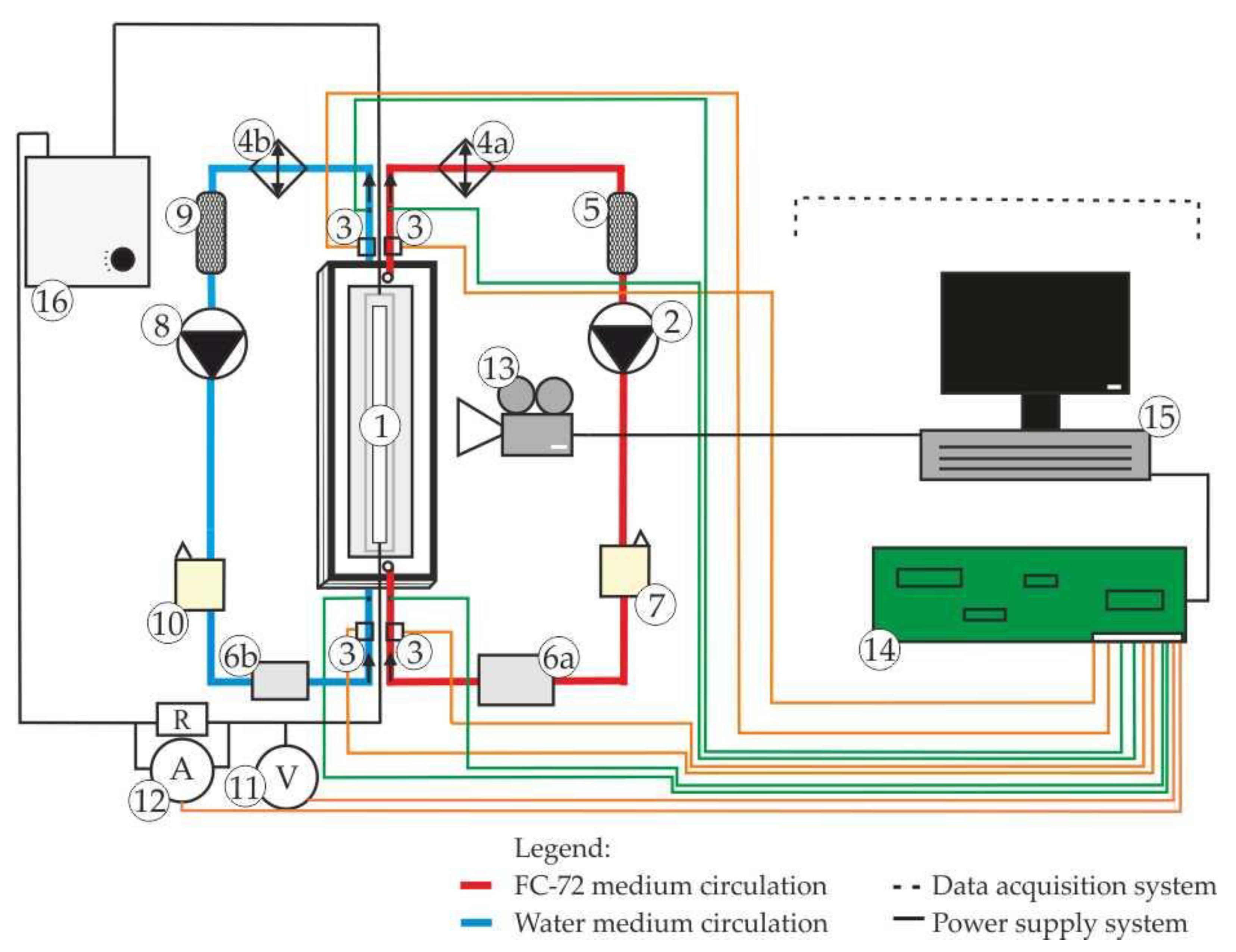
Figure 1. Schematic diagram of the experimental stand: 1—test section with mini-channels, 2,8—circulating pumps, 3—pressure meter, 4a, 4b—heat exchanger, 5,9—filters, 6a—mass flow meter, 6b—magnetic mass flow meter, 7,10—air separators, 11—ammeter, 12—voltmeter, 13—infrared camera, 14—data acquisition station, 15—PC computer, 16—power supply, (R)—a shunt.
Energies 15 01340 g001
Figure 2. View of the test section with mini-channels: (a) 3D visualization, (b) view of the compact heat exchanger components: 1,9—aluminum covers, 2,8—silicone gaskets, 3—Haynes-230 alloy heated plate with electrodes, 4—silicone gasket forming the hot mini-channel, 5—copper plate between two mini-channels, 6—silicone gasket forming the cold mini-channel, 7—Haynes-230 alloy plate.
Energies 15 01340 g002
Figure 3. Schematic diagram of the test section: 1—the hot mini-channel (FC-72), 2—the cold mini-channel (distilled water), 3,4—outer casing silicon gasket, 5,10—Haynes-230 alloy plate, 6—copper plate, 7—thermocouple, 8—pressure meter, 9—Hastelloy X alloy electrode.
Energies 15 01340 g003
Figure 4. Diagram of the test section (pictorial view, not scaled).
Energies 15 01340 g004
Figure 5. (a) Thermograms on the outer surface of the heated plate outer surface; (b) temperature of the heated plate vs. distance from the mini-channel inlet.
Energies 15 01340 g005
Figure 6. Two-dimensional temperature fields of: the heated plate TH, fluid FC-72 TFC, and the copper plate TCu obtained using the Trefftz method at the following heat flux value: (a) q = 12.26 kW/m2 and (b) q = 33.93 kW/m2; experimental parameters are given in Table 3 (pictorial view, not scaled).
Energies 15 01340 g006
Figure 7. Heat transfer coefficient α 1 according to (a) 1D approach, Equation (17) and (b) 2D approach, Equation (13), both vs. distance from the mini-channel inlet.
Energies 15 01340 g007
Figure 8. The maximum relative differences between the values of the heat transfer coefficient α 1 calculated from Equations (13) and (17).
Energies 15 01340 g008
Figure 9. Heat transfer coefficients α2 at the FC-72—copper plate contact surface versus the distance from the mini-channel inlet; calculated according to: (a) 2D approach, Equation (14); (b) Cooper correlation, Equation (19); (c) Mikielewicz correlation, Equation (20) and (d) Dutkowski correlation, Equation (22).
Energies 15 01340 g009
Figure 10. Maximum relative differences between heat transfer coefficients α2 determined from the Equation (14) and from correlations listed in Table 2.
Energies 15 01340 g010
Figure 11. The heat transfer coefficient α 1 with error bars for q = 12.26 kW/m2 obtained by: (a) the 1D approach, Equation (17) and (b) the 2D approach, Equation (13), both vs. distance from the mini-channel inlet.
Energies 15 01340 g011
Table 1. Characteristics of the main apparatus and uncertainty of measurement.
ParameterDeviceManufacturer/
Type/Model
Basic Technical DataMeasurement RangeMaximum Uncertainty of Measurement
Temperature of the heated plate TH,IRThermal imaging cameraFLIR A655SCSpectrum range:
7.5 ÷ 14 µm
Resolution:
640 × 480 pixels
−40–150 °C
100–650 °C
±2 °C or ±2% of reading *
Temperature of FC-72
TFC,in, TFC,out
Temperature of water
Tw,in, Tw,out
ThermocoupleK-type
Thermocouple,
Czaki
Thermo-Product,
type K 221 b
NiCr, NiAl sensor
with a galvanically isolated weld
−40–375 °CCalibration tolerance 1.5 °C [28]
Gauge pressure at the hot mini-channelPressure meterEndress + Hauser,
Cerabar S PMP71
Working temperature −25 ÷ +55 °C0–10 bar±0.05% of reading [23]
Gauge pressure at the cold mini-channelPressure meterWika, A-10Output signal:
4 ÷ 20 mA
DC supply: 8 ÷ 30 V
0–10 bar0.5% of full scale *
Atmospheric pressurePressure meterWika, A-10Output signal:
4 ÷ 20 mA
DC supply: 8 ÷ 30 V
0–2.5 bar0.5% of full scale *
Mass flow rate of FC-72
(the hot mini-channel)
Coriolis mass flow meterEndress + Hauser, Proline Promass A 100Nominal diameter:
4 mm
Medium temperature: up to +205 °C
0–0.125 kg/s±0.1% of reading [23]
Mass flow rate of distilled water
(the cold mini-channel)
Magnetic mass flow meterSM6004Nominal diameter:
15 mm
Medium temperature: up to +205 °C
6–1500 kg/s±0.2% of reading *
Current, VoltageAmmeter VoltmeterDatafort
hMeasuring
Module
8b32-01
Data Acquisition Station
MCC SC-1608G Series
1500 Vrms Isolation,
Input Protection:
Continuous 40VAC,
ANSI/IEEE Transient C37.90.1,
Power Supply Voltage: +5VDC ± 5%,
Power Supply Current: 30 mA,
Power Supply
Sensitivity: ±75 ppm/%
4 mA–20 mA
0 V–5 V or
0–10 V
±0.05%
Accuracy *
±0.02%
hLinearity *
* according to the data provided by the apparatus manufacturer.
Table 3. Main fluid properties and experimental data.
Physical Properties/
Experimental Data
Fluorinert FC-72Distilled Water
Number of heat flux setting#1#2#3#4#1#2#3#4
Heat flux,
q [kW/m2]
12.2618.7025.9433.9312.2618.7025.9433.93
Main physical properties
Thermal conductivity,
λl [W/(mK)]
0.0620.0620.0620.0620.590.590.590.59
Density,
ρl [kg/m3]
1721.21723.71723.21720.8999.2999.2999.2999.2
Main experimental data
Mass flow rate,
Qm [kg/s]
0.00910.00910.00910.00910.005150.005590.004890.00556
Temperature,
Tl,in [K]
296.25293.65291.95290.85286.55286.45286.45286.45
Temperature,
Tl,out [K]
299.45300.55302.55305.05289.25288.95289.05289.25
Gauge pressure,
pin [Pa]
9000900011,00014,00048,02033,44056,89066,430
Gauge pressure,
pout [Pa]
900010,00012,00016,00025,98018,82026,51057,150
Table 4. Values of selected dimensionless numbers, the overall heat transfer coefficient and the Fanning friction factor.
Number of Heat Flux Setting#1#2#3#4
ReFC1113.811098.321097.361106.20
Rew536.13580508.24577.92
PrFC11.5511.5411.5111.25
Prw8.068.118.108.07
GzFC151.36157.50157.18145.99
Gzw50.8655.3648.4354.91
k790.021203.181554.232018.38
f F C 0.0200.0210.0210.020
f w 0.0420.0390.0440.039
Table 5. Mean relative errors of heat flux and heat transfer coefficients calculated from one- and two-dimensional approaches.
The Mean Relative Error [%]
Number of Heat Flux Setting q α 1 , 1 D α 1 , 2 D α 2 , 2 D
#11.4112.9314.614.7
#21.119.4610.710.8
#30.938.8210.410.5
#40.088.939.910.1
Publisher’s Note: MDPI stays neutral with regard to jurisdictional claims in published maps and institutional affiliations.