Article

Mechanism of Magnetic Nanoparticle Enhanced Microwave Pyrolysis for Oily Sludge

1
College of Petroleum Engineering, Xi’an Shiyou University, Xi’an 710065, China
2
Shaanxi Key Laboratory of Advanced Stimulation Technology for Oil & Gas Reservoirs, Xi’an Shiyou University, Xi’an 710065, China
3
Offshore Oil Production Plant of Shengli Oilfield, SINOPEC (China Petroleum & Chemical Corporation), Dongying 257237, China
*
Author to whom correspondence should be addressed.
Energies 2022, 15(4), 1254; https://doi.org/10.3390/en15041254
Submission received: 11 January 2022 / Revised: 4 February 2022 / Accepted: 6 February 2022 / Published: 9 February 2022

Abstract

:
In view of the high dielectric constant of magnetic nanoparticles, this paper intends to use it as a new type of microwave absorbing medium to accelerate the microwave pyrolysis process of oily sludge. Microwave thermogravimetric reaction and pyrolysis product staged collection devices were established, respectively. The main stage of pyrolysis process of oily sludge was divided based on the thermogravimetric experiments. Mechanism was studied through the characteristics of pyrolysis products and reaction kinetics simulation. Experimental results showed that the addition of magnetic ZnFe2O4 particle did not change the microwave pyrolysis process of oily sludge and the pyrolysis efficiency could be improved. Pyrolysis process was divided into three stages, rapid heating and water evaporation stage (20~150 °C), light component evaporation stage (150~240 °C) and heavy component cracking stage (240~300 °C). Due to the addition of magnetic ZnFe2O4 particles, the content of C4~C12 increased by 3.5%, and the content of C18+ decreased by 4.1%, indicating that more recombinant components participated in the reaction pyrolysis to form light gas components. The kinetic analysis showed that the activation energy of oily sludge decreased by 36.49% and the pre-exponential factor decreased by 91.39% in stage III, indicating that magnetic nanoparticles had good catalytic activity.

1. Introduction

Oily sludge refers to sludge mixed with crude oil, various refined oils, residual oils and other heavy oils. Oily sludge is not inherent in nature but is a mixture of oil, soil, and water, even mixed with other pollutants from oilfield exploitation, the oil refining process, transportation, use, and storage. Oily sludge is harmful to human beings, plants and water organisms and is one of the main pollutants in the petroleum and petrochemical industries [1]. Therefore, research on the reduction and harmless treatment of oily sludge has always been an important issue in oil production [2].
Domestic and foreign experts and research groups have proposed a variety of treatment methods in relation to oily sludge [3]. Qin et al. [4] used circulating fluidized bed pyrolysis of 1 kg oily sludge; energy consumption was only 2.4~2.9 MJ, greatly saving energy. However, attention should be given to the secondary pollution of oil sludge after drying. Hu [5] used low-temperature pyrolysis technology to treat oily sludge in the Tahe Oilfield, and the oil recovery rate reached 62.3%. From the current research situation, compared with other treatment methods, pyrolysis shows a higher energy utilization rate and easier operation in the treatment of oily sludge [6]. However, the use of conventional heating methods for the pyrolysis of oily sludge may lead to higher energy losses, equipment maintenance and operating costs [4,7,8]. Therefore, it is urgent to develop new pyrolysis technology to solve the problems of excessive energy consumption and a low resource recovery rate in the pyrolysis process of oily sludge.
Microwaves are a high-frequency electromagnetic wave, different from the traditional heating method. It is the overall heating of material caused by dielectric loss in an electromagnetic field, and its energy is transmitted in the form of electromagnetic waves through space or medium. Compared with other traditional heating methods, microwave heating has the advantages of saving energy consumption, improving efficiency, controllable processes and clean heating links [9]. The loss and transmission of energy in the electromagnetic field can distinguish the structural state inside the heating object and thus can exert the ‘thermal effect’ and ‘nonthermal effect’ of microwaves [10]. Supporters of ‘thermal effect’ believe that microwave accelerates the reaction only because the reaction temperature increases rapidly. Under high temperature and high pressure, the reaction rate was also greatly improved. Supporters of ‘nonthermal effect’ believe that microwave selective heating of polar substances can reduce pre-exponential factor and activation energy. The electric field in the electromagnetic field can stabilize the polarity transition state, reduce the activation energy and improve the reaction speed [11,12,13]. Therefore, microwaves can selectively pyrolyze macromolecular substances such as colloids and asphaltenes in oily sludge, reduce toxic and harmful polymers in macromolecules, and improve the state and properties of oil products to better realize the goal of resource utilization, reduction and harmlessness of oily sludge.
However, microwave pyrolysis of oily sludge alone is often selective to the heating medium in the microwave electromagnetic field environment. According to the heating properties of dielectrics, microwaves can effectively heat polar substances. For nonpolar substances with molecular structures, the effect is poor even though they do not directly heat. Through experiments, researchers found that adding microwave absorbers such as SiC, Fe2O3, graphite, activated carbon and pyrolytic coke powder to the heating material can make the pyrolysis effect more significant [14,15,16]. Salema et al. [17] found that the addition of biochar as a material with good dielectric properties to oily sludge could significantly improve the heating rate of microwave pyrolysis and promote the decomposition of hydrocarbon substances in oily sludge. Wan, Tian, Wang et al. [18,19,20] investigated the effects of using Fe2O3, activated carbon, SiC and carbonized sludge as microwave absorbents on the microwave pyrolysis of oily sludge and concluded from the experimental results that the additive could effectively reduce the sludge volume. Chen et al. [21] used granular activated carbon as a catalyst to catalyze microwave pyrolysis of oily sludge, obtaining pyrolysis oil with a high concentration of diesel and gasoline (about 70% of pyrolysis oil), and inhibiting the leaching of heavy metals. Dominguez et al. [22,23] added activated carbon as absorbent in oily sludge and set up two groups of experiments of conventional heating and microwave heating, respectively. The experimental results show that the amount of H2 and CO in the pyrolysis products of oily sludge with activated carbon is increased under microwave radiation, and the content of toxic and harmful substances in the gas phase products is reduced. Menendez et al. [24,25] added graphite or coke as a microwave absorbent to oily sludge, and the temperature of sludge could quickly reach 900 °C within 2 min. Shie et al. [26] found that the addition of Fe, FeCl3, Al and Al2O3 (metal absorbent) will significantly reduce the content of carbon in the residue, and the addition of Fe2O3 will improve the quality of the magnetic recovery condensate. Azadeh B. Namazi et al. [27] added KOH to the sludge. Through experimental exploration, KOH as an alkaline absorbent was found to not only greatly reduce the time of microwave pyrolysis of sludge but also reduce the apparent activation energy in the chemical reaction process.
Although the performance and efficiency of microwave pyrolysis are improved to some extent by adding microwave absorbent to oily sludge, the experimental results still show that the pyrolysis conversion or pyrolysis efficiency (pyrolysis efficiency refers to the percentage of material decomposed into biogas and bio-oil by heating [28].) is still not ideal after adding some microwave medium, and the treatment cost and energy consumption are generally high. Therefore, it is urgent to seek a new microwave absorption medium to strengthen the pyrolysis effect of microwaves on oily sludge.
In recent years, nanotechnology has advanced by leaps and bounds. A new type of nanomaterial, magnetic nanoparticles, has attracted increasing attention from scientific and technological workers around the world [15]. Mario et al. [29] believe that the adsorption performance of magnetic nanoparticles depends largely on its particle size. The smaller the particle size of magnetic nanoparticles, the larger the corresponding specific surface area, the more obvious the surface effect and other characteristics, and the stronger the adsorption capacity. Ali et al. [30] observed through experiments that magnetic nanoparticles can be stably distributed at the oil-water interface, indicating that magnetic nanoparticles have good interfacial activity. Magnetic nanoparticles not only have magnetic responsiveness but also have unusual magnetic properties that conventional nanoparticles do not have [31,32,33]. In view of the characteristics of magnetic nanoparticles with a high dielectric constant and permeability, as well as less environmental pollution, they are considered to be a new microwave absorption medium for accelerating the microwave pyrolysis process of oily sludge. Conversion of more electromagnetic energy into heat energy is intended, with acceleration of the heat absorption of oily sludge. Combined with magnetic nanoparticles and microwaves, the sedimentation performance of sludge can be improved. The rupture of microbial cells can be exacerbated, and the dissolution of organic solids in oily sludge can be promoted [34,35]. In addition, magnetic nanoparticles have good separation performance in the external environment. Nariya et al. [36] reported synthesis of Silver nanocomposite using β-cyclodextrin (b-CD) maleic anhydride crosslinked polymer anchored on the surface of magnetic nanoparticles. They found that the catalyst exhibited high recycling efficiency (up to 5 cycles) and ease of operation under mild conditions. Coutinho et al. [37] studied the synthesis process of HA/Co Fe2O4 composite and its application in magnetic fields promoting enzyme recovery. They found that the material exhibited good reusability, especially in the case of the beta-glucosidase biocatalyst, which could be reused 10 times and maintained about 70% of its initial activity. Magnetic nanoparticles can be recycled and can greatly reduce the treatment cost of oily sludge pyrolysis.
In order to study the mechanism of magnetic nanoparticles enhanced microwave pyrolysis of oily sludge, it is very important to establish the kinetic equation of pyrolysis reaction according to Arrhenius law. The reaction mechanism function is determined by analyzing the characteristics of microwave pyrolysis products, and then the equation is solved by the integral method. The reaction order is determined by the microwave thermogravimetric analysis experiment. It is necessary to obtain the variation of pyrolysis temperature with reaction time and the weight of oily sludge with reaction time by the thermogravimetric curves. However, the traditional thermal gravimetric analyzer is not operated under the condition of microwave pyrolysis. Besides, it is difficult to obtain pyrolysis products at different stages in one experiment through the conventional pyrolysis product collection devices. Therefore, it is urgent to design and develop a microwave thermal gravimetric analysis and pyrolysis product staged collection system. In general, the kinetic equation uses mainly isothermal or nonisothermal curves for linear regression, determines the most reasonable mechanism function by comparing the correlation degree of the linear relationship, and calculates the dynamic parameters by the intercepts of regression line [38]. Shie et al. [39] proposed first, second and third reaction kinetics models to describe the pyrolysis kinetics of oily sludge, and gave the best fitting of three reaction models. However, due to the complex composition of oily sludge and unclear pyrolysis mechanism, higher requirements are put forward for the selected reaction mechanism function. Besides, the experimental verification of kinetic equation is more difficult.
In general, research on the treatment of oily sludge with magnetic nanoparticles is still limited, and related research on the treatment of oily sludge by magnetic nanoparticles combined with microwaves is rarely reported at home or abroad. Therefore, it is necessary to carry out relevant research to provide a theoretical basis for magnetic nanoparticle-enhanced microwave pyrolysis of oily sludge. This paper intends to carry out thermogravimetric experiments with magnetic nanoparticles combined with microwave pyrolysis of oily sludge on the self-established microwave thermogravimetric reaction and pyrolysis product staged collection devices. The main stage of pyrolysis process of oily sludge was divided based on the thermogravimetric experiments. The process routine of magnetic nanoparticle enhanced microwave pyrolysis for oily sludge was studied through the characteristics of pyrolysis products and reaction kinetics simulation. This study will be of great significance for giving full exert to the unique advantages of microwaves, strengthening the effect of microwaves and improving pyrolysis efficiency.

2. Experimental Apparatus and Methods

According to previous research reports, microwave pyrolysis of oily sludge can reduce the activation energy. Therefore, some researchers try to carry out kinetic simulation research on microwave pyrolysis. However, the premise of the simulation study is to obtain the variation in the weight loss rate and heating rate of oily sludge with temperature in a certain temperature range by microwave thermogravimetric analysis. Therefore, microwave thermogravimetric analysis experiments are a prerequisite for studies of product characteristics and kinetic simulations in each stage of the pyrolysis process. The traditional thermogravimetric analysis method cannot meet the needs for thermogravimetric analysis of microwave heating. Therefore, based on the existing microwave heating devices, this paper independently designed and established a set of microwave thermogravimetric reaction and pyrolysis product staged collection devices. The device structure is more reasonable, the measurement is more accurate and the operation is more convenient.
The experimental device consists of two parts: a microwave thermogravimetric device and a pyrolysis product staged collection device. Schematic diagrams are shown in Figure 1 and Figure 2. A microwave thermogravimetric device is used mainly for microwave thermogravimetric experiments, and the pyrolysis stage of oily sludge is divided according to the heating curve and weight loss rate curve obtained from the experiment. The pyrolysis product staged collection device was used mainly to collect the gas products and the liquid products after pyrolysis in different stages, which was convenient for the subsequent analysis of pyrolysis product components and the study of the mechanism of reaction kinetics.

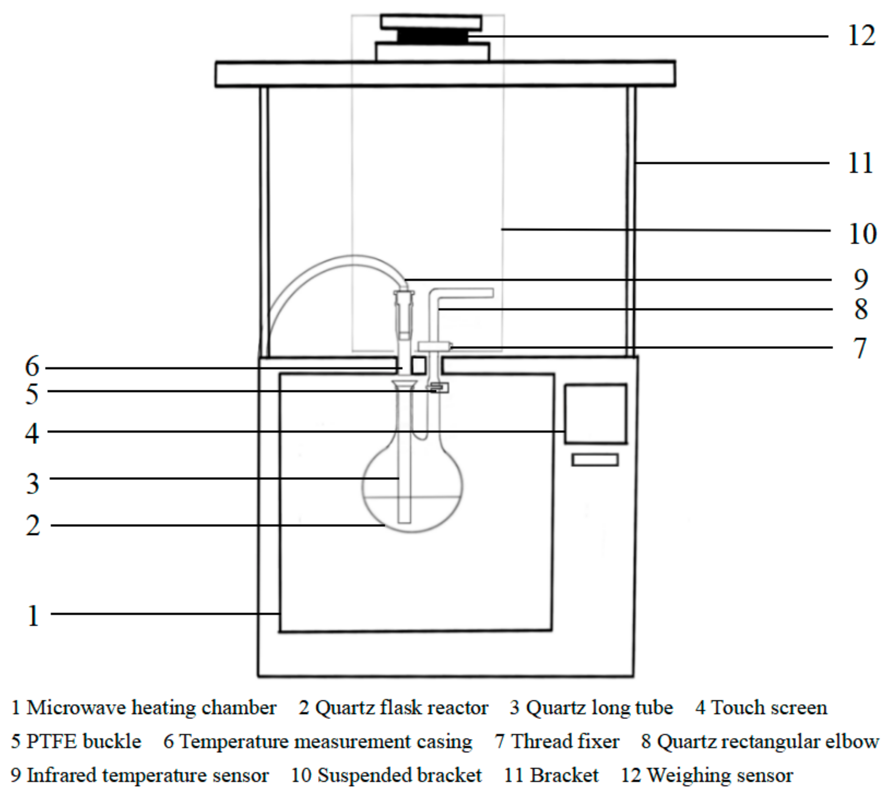
2.1. Microwave Thermogravimetric Device

As shown in Figure 1, the schematic diagram of the microwave thermogravimetric device consists of a rectangular microwave heating chamber (MAS-II, SINEO, Shanghai, China), quartz flask reactor, quartz long tube, temperature measurement casing, infrared temperature sensor, quartz rectangular elbow, polyfluorotetraethylene (PTFE) buckle, weighing sensor, touch screen, bracket and thread fixer.
Microwave thermogravimetric methods are as follows: First, the quartz flask reactor is placed in a microwave heating chamber, and the configured oily sludge sample is added into the quartz flask reactor. Then, the quartz long-tube is inserted into the middle port of the quartz flask reactor, and the port is aligned with the center of the temperature measurement casing. The infrared temperature sensor is inserted into the temperature measurement casing to measure the temperature directly. The right port of the quartz flask reactor and quartz rectangular elbow are connected by a PTFE buckle, and the lower end of the suspended bracket and quartz rectangular elbow is connected by a thread fixer. The upper end of the suspended bracket is placed on the weighing sensor. During the experiment, the touch screen displays the temperature measurement data, weighing data, heating rate curve and weight loss rate curve in real time. After connecting the experimental device, the power supply is connected, and the microwave heating power and time are set (the microwave was operated at 2450 MHz). Then, the device is started, and the experimental phenomenon is observed. The system collects a set of data every second. After the reaction, the temperature data, weight data, heating rate curve and weight loss rate curve in the reaction process are derived.

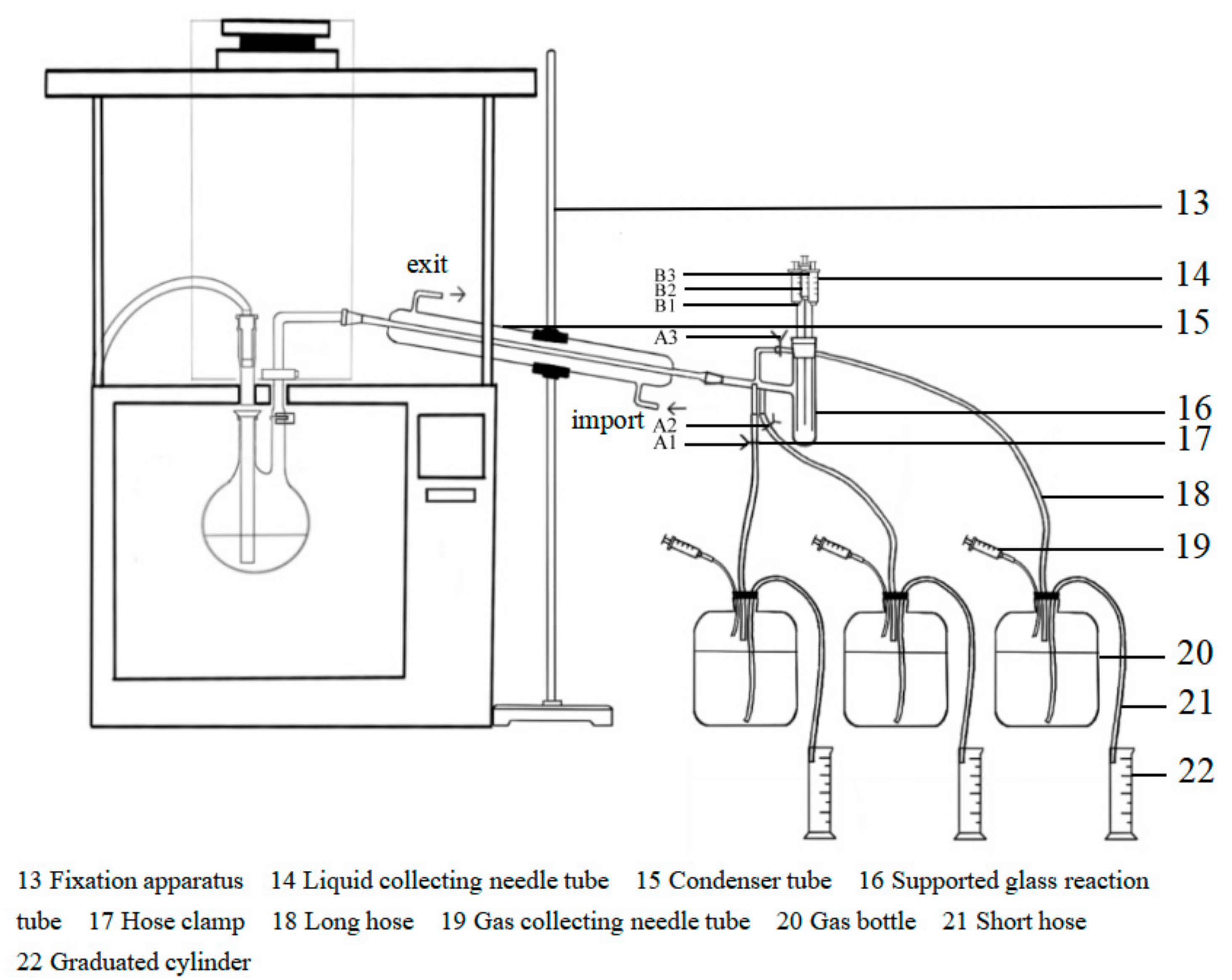
2.2. Pyrolysis Product Staged Collection Device

According to the present study, microwave pyrolysis of oily sludge could be divided into three pyrolysis reaction stages. To further clarify the process mechanism of magnetic nanoparticles combined with microwave treatment of oily sludge, a staged collection device for pyrolysis products was designed. This staged collection device increases the pyrolysis product staged collection function based on Section 2.1. According to the thermogravimetric curves obtained by the microwave thermogravimetric device, three pyrolysis reaction stages are divided, and then the reaction products of each stage are collected by the device.
A schematic diagram of the pyrolysis product staged collection device is shown in Figure 2. Based on the microwave thermogravimetric device, this device adds a condenser tube, supported glass reaction tube, liquid collecting needle tubes, hoses, gas collecting needle tubes, gas bottles and graduated cylinders but does not weigh them. The quartz rectangular elbow is connected to the condenser tube, and the supported glass reaction tube is connected to the condenser tube. There are three liquid collecting needle tubes at the reaction tube interface. The branch of the reaction tube has three small holes, each of which is connected with a long hose and a hose clamp. The long hose is passed into the gas bottle, and each gas bottle is also connected with a gas collecting needle tube and a graduated cylinder with a short hose.
The pyrolysis product staged collection method is as follows: First, the oily sludge sample in the same amount as the microwave thermogravimetric experiment is added to the quartz flask reactor. The experimental device is connected to the nitrogen purge. Then, the connected power supply is set to the same microwave heating power and time as in the thermogravimetric experiment. Second, the device is started. Hose clamps A2 and A3 are closed, and A1 is opened. The pyrolysis products are directly entered into the supported glass reaction tube through the condenser tube. When the pyrolysis temperature reaches the maximum temperature of stage I, the liquid products after condensation are collected by liquid collecting needle tube B1. Third, the hose clamps A1 and A3 are closed, and A2 is opened. When the pyrolysis temperature reaches the maximum temperature in stage II, B2 is used to collect the product. Then, the hose clamps A1 and A2 are closed, and A3 is opened. When the pyrolysis temperature reaches the maximum temperature in stage III, B3 is used to collect the product. Finally, the volume of oil and water is measured after standing. At the same time, the gas products are collected by the gas collecting needle, and the gas production is measured by the drainage method.

2.3. Preparation of Oily Sludge

The crude oil used in this paper was from a block in the Changqing Oilfield. First, the crude oil was put into an oven and heated to 80 °C for 2 h. Then, the crude oil was put into a vacuum drying oven (DZ-1BL, FAITHFUL, China), cooled to room temperature, and allowed to stand for 48 h for later use. The sludge used in this paper was taken from the campus. The sludge was sieved to remove the larger particles, heated to 110 °C in the oven and dried to constant weight. Then, the sludge was put into a vacuum drying oven and cooled to room temperature. Finally, the sludge was broken into powder with a high-speed crushing machine (BO-1000S1, BOOV, China) and then filtered by a particle size separator with a 40-mesh screen. Then, the powdered sludge was put into a drying dish for later use [21].
The preparation method for oily sludge samples was as follows: first, based on the prototype of oily sludge from a block in the Changqing Oilfield, we added the sample to a beaker in the order of sludge-water-oil, and the sample was preliminarily mixed with a stirring rod. The ratio of oil, sludge and water was 2:2:1. Second, the sample was heated in a water bath at 50 °C, and at the same time, the sample was stirred using a mechanical stirrer with a stirring speed of 1000 r·min−1 for 30 min. Third, the sample was kept stable with a cover for 24 h.
Through the preliminary experimental results of our team [40], we selected nanoZnFe2O4 as the absorbing medium in this paper because of its stronger absorbing ability and larger magnetic saturation [16]. NanoZnFe2O4 was provided by Aladdin Chemical Reagent Network. The mass concentration of nanoZnFe2O4 was 5 mg/g, and the particle size was 30 nm.

2.4. Reaction Kinetics Equation

One of the main purposes of studying kinetics by thermal analysis is to determine the kinetic equations that can describe the reaction and determine the corresponding reaction mechanism. This method uses mainly isothermal or nonisothermal curves for linear regression, determines the most reasonable mechanism function by comparing the correlation degree of the linear relationship, and calculates the dynamic parameters by the intercepts of regression line. The reaction mechanism function represents a functional relationship between the material reaction rate and the reaction conversion, which is the key to studying the kinetic equation.
The experimental verification of oily sludge kinetic equation puts forward higher requirements for the selected reaction mechanism function. According to the thermogravimetric curve of magnetic particles combined with microwave, the pyrolysis process was divided into several main stages, and the kinetics of each stage was studied. In this part, the kinetic equation of pyrolysis reaction was first established according to the Arrhenius law, the reaction mechanism function was determined by analyzing the characteristics of microwave pyrolysis products, and then the function was solved by Coats–Redfern integral method. Secondly, the reaction order was determined by the microwave thermogravimetric analysis experiment in each stage, and thus the kinetic activation energy and pre-exponential factor were obtained and the kinetic equation of microwave thermal decomposition enhanced by magnetic nanoparticle for oily sludge was determined. Finally, the process mechanism of microwave pyrolysis of oily sludge enhanced by magnetic nanoparticle was further analyzed [41].
According to the law of mass conservation, under the condition of constant heating rate, the reaction conversion can be described by the weight change of oil, namely,
α = W T W 0 W f W 0
where α, WT, W0, Wf represent the solid conversion of oily sludge at the temperature T, the mass of oily sludge at the temperature T, the initial mass of oily sludge and the mass of oily sludge at the end of reaction, respectively.
The most basic assumption for thermal analysis kinetics study is that the Arrhenius equation that represents the relationship between chemical reaction rate and temperature can be used for thermal analysis reaction [42], so for the decomposition reaction, the decomposition rate can be expressed as
d α d t = k f ( α )
k = A exp ( E R T )
In Equation (3), A, E, R and T are frequency factor or pre-exponential factor, activation energy, ideal gas constant and measurement temperature, respectively. f(α) is the mechanism function of reaction.
Therefore,
d α d t = A exp ( E R T ) f ( α )
For non-isothermal experiments, the heating rate β is expressed as follows:
β = d T d t
d α d T = A β exp ( E R T ) f ( α )
Then, according to the microwave thermogravimetric experiment and product characteristics analysis, the process of magnetic nanoparticles enhanced microwave pyrolysis of oily sludge is analyzed, and the reasonable reaction mechanism function was determined [43]. Here, it is assumed that the pyrolysis kinetic reaction order of oily sludge is one order, then a simple pyrolysis mechanism function of oily sludge can be obtained,
f ( α ) = ( 1 α ) n
d α ( 1 α ) n = A β exp ( E R T ) d T
In the above equations, n is the reaction order. The reaction order is also called the total reaction order, which is the algebraic sum of the reaction order of each group. The size of the reaction order represents the influence of concentration on the reaction rate. The greater the order is, the greater the influence is. Equation (8) is a kinetic simulation equation, and the parameters of the equation are solved by integral or differential methods.
In this paper, Coats-Redfern empirical integral method was used to solve the expressions as follows:
ln [ ln ( 1 α ) T 2 ] = ln [ A R β E ( 1 2 R T E ) ] E R T ,       ( n = 1 )
ln [ 1 ( 1 α ) 1 n T 2 ( 1 n ) ] = ln [ A R β E ( 1 2 R T E ) ] E R T .       ( n 1 )
First, the reaction order of mechanism function is assumed, and then the linear regression is carried out by using the experimental data. A straight line with −1/T as the independent variable and Y = ln [ 1 ( 1 α ) 1 n T 2 ( 1 n ) ] as the dependent variable is obtained by linear regression fitting. In Equation (10), β is approximately the slope of a linear fitting of temperature versus time and we assume that T in (1 − 2RT/E) is the average temperature in pyrolysis process. Finally, the apparent activation energy E and pre-exponential factor A are calculated by the intercepts of the straight line and the reaction kinetics equation is determined.

3. Results and Discussion

3.1. Thermogravimetric Curve Analysis

Microwave thermogravimetric experiments are the primary task in the study of the mechanism of the microwave pyrolysis process. This section focuses on studying the relationship between the weight and temperature of oily sludge with microwave time. Thermogravimetric curves were drawn, providing data support and a theoretical basis for the pyrolysis reaction kinetics simulation.
Two oily sludge samples of 80 g each were heated by microwave, one without magnetic nanoparticles as the blank sample and the other with nanoZnFe2O4 particles of 5 mg/g mass concentration as the control sample. The microwave power was set to 800 W, and the temperature and mass in the reaction process were recorded.

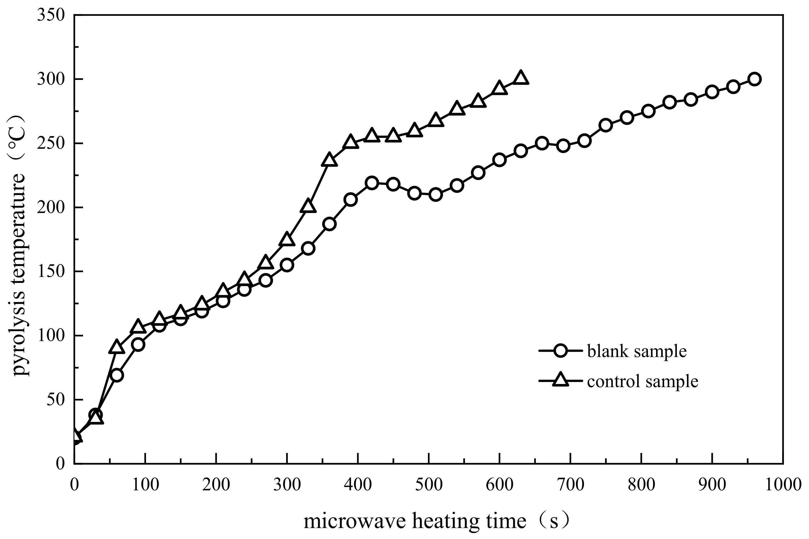
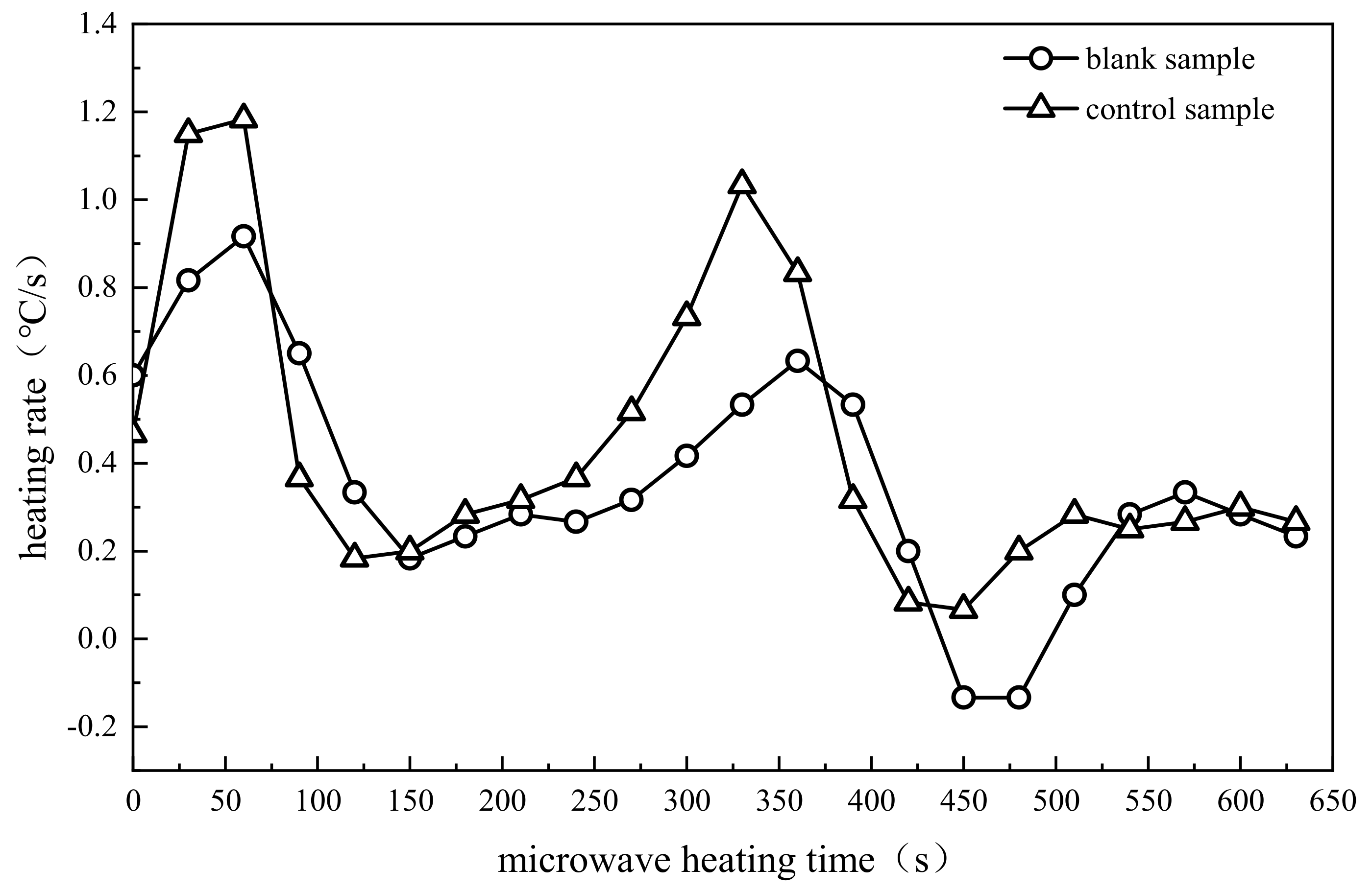
3.1.1. Comparative Analysis of Pyrolysis Temperature

The microwave pyrolysis effects of the blank and control samples were investigated by the pyrolysis temperature and heating rate. The variation curves of the microwave pyrolysis temperature with time for the two samples are shown in Figure 3, and the variation curves of the heating rate with time are shown in Figure 4.
The temperature comparison of the control and blank samples in Figure 3 shows that they exhibited a similar upward trend over time and could be roughly divided into three processes. When the heating time was between 0 s and 150 s, the temperature of the oily sludge increased the fastest. The heating time was approximately 20 s, and the pyrolysis temperatures of the two samples rapidly reached 50 °C. Later, the heating rate in the control sample was obviously higher than the heating rate in the blank sample, which led to 10 s earlier to reach 100 °C in the process of heating. At this stage, water from the oily sludge continuously absorbed heat and evaporated into water vapor. At this moment, the pyrolysis process entered a relative balance of heat absorption and heat dissipation. When the heating time was between 150 s and 500 s, the growth rates of the pyrolysis temperature were relatively rapid in the two samples. When the heating time was between 500 s and 960 s, the growth rates of the temperature were relatively slow. When the heating time was 420 s, the temperature of the control sample reached 252 °C and the temperature of the blank sample was 210 °C, which indicated that the pyrolysis temperature of the oily sludge with magnetic nanoparticles reached a higher value in the same time. When the pyrolysis temperature reached 280 °C, the microwave heating time of the control sample was 560 s, and the microwave heating time of the blank sample was 870 s. The heating time was shortened by 35.63%. This result indicated that the microwave heating time of oily sludge with magnetic nanoparticles added was shorter at the same pyrolysis temperature.
The heating rates of the two samples in Figure 4 presented two wave peaks. The first wave peak of the heating rate appeared between 50~80 s because there were many water molecules existing in the oily sludge, and water molecules were strongly polar molecules formed by the junction of ionic bonds. Therefore, it was easy to absorb microwave energy in the process of pyrolysis and convert the microwave energy into heat energy. When the heating time was between 100~120 s, the heating rate slowed down. At this stage, the heat release of the oily sludge during microwave pyrolysis and the heat absorption by water molecule evaporation reached a relative equilibrium state. When the heating time was between 150~200 s, the low molecular weight hydrocarbons were continuously generated with increasing pyrolysis temperature, and the evaporation enthalpy became low. The heat could be fully absorbed and led to a further increase in the heating rate. When the heating time exceeded 200 s, the heating rate slowed down slightly again because the light oil components separated at this stage, and the pyrolysis process returned to the relative heat balance of heat absorption and release. When the heating time exceeded 240 s, the second wave peak of the heating rate appeared. Then, when we continued to extend the microwave heating time, an irregular wave phenomenon also appeared similar to that after the first wave peak of the heating rate because the pyrolysis process started to transition from light components to heavy components as the pyrolysis temperature of the oily sludge continuously increased, a process that was associated with complex chemical and physical reactions and a series of heat absorption and release phenomena.
The variations in heating rates between the control and blank samples were basically the same, indicating that the addition of magnetic nanoparticles did not change the microwave pyrolysis process of oily sludge. Relatively, the heating rate of the control sample was significantly higher than the heating rate of the blank sample because magnetic nanoparticles are nanomaterials with magnetic responsivity, which are conducive to microwave absorption and could improve the microwave heat absorption efficiency [44].

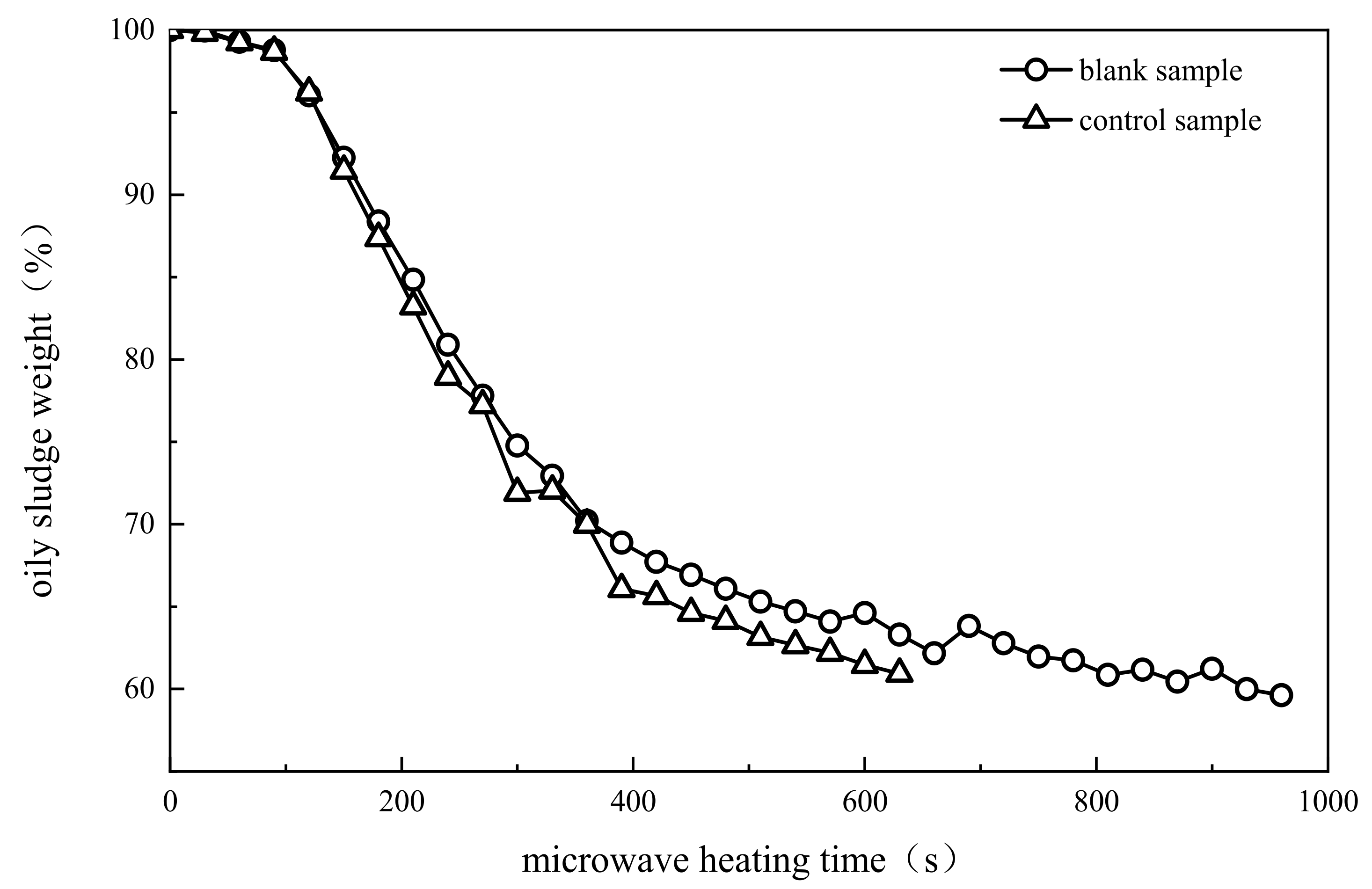
3.1.2. Comparative Analysis of Oily Sludge Weight

The variation curves of oily sludge weight for the blank and control samples during microwave pyrolysis over time are shown in Figure 5.
To further explore the weight change of oily sludge with magnetic particle addition, this plot shows the variation curves of the weight loss rate of oily sludge during microwave pyrolysis over time in the range of 0~650 s, as shown in Figure 6.
As shown in Figure 5, the weight variation trends of the control and blank samples were basically consistent within 0~150 s. In this process, a large amount of water in the oily sludge evaporated. As water is a polar molecule, it reacts violently after reaching its boiling point under the action of the microwaves. Through the high-speed camera, we observed that the oily sludge in the reaction vessel also exhibited a roll phenomenon. When the heating time exceeded 150 s, the weight losses of oily sludge in the two samples increased, and the gap gradually widened. When the microwave heating time reached 630 s, the weight of oily sludge in the control sample dropped from the initial 100% to 59%, the weight of oily sludge in the blank sample dropped to 66%, and the weight loss ratio increased by 7%.
From Figure 6, we found that with increasing heating time, the trends of the weight loss rate curves of the two samples were basically consistent. Overall, the absolute value of the weight loss rate of oily sludge first increased, then decreased gradually, and finally tended to fluctuate slightly. From the beginning of heating to 100 s, the curves of the weight loss rates of the two samples showed good agreement, after which the weight loss rate of the control sample was significantly larger than the weight loss rate of the blank sample because magnetic nanoparticles exert their unique quantum size effect when enhancing the microwave pyrolysis of oily sludge. This effect caused the electron energy level of the nanoparticles to split when the electron energy level interval was within the microwave energy range, thus forming a new absorbed channel. The special structure of grain boundaries and grain boundary atoms at high concentrations led to the intensification of the movement of atoms and electrons in the material under irradiation with an electromagnetic field, which promoted magnetization and finally converted more electromagnetic energy into heat energy. When the microwave heating time was between 300~350 s, the absolute value of the weight loss rate in the blank sample was greater than the absolute value of the weight loss rate in the control sample.
The reason for this phenomenon may be that the control sample at that moment had finished the water evaporation process in which the weight loss rate was fastest and entered into the stage of evaporation of light hydrocarbon components. When the temperature was between 150~240 °C, as shown in Figure 3, the reaction process was slower, and weight loss was not obvious. When the heating time was between 350~600 s, Figure 3 shows that the temperature had reached above 240 °C. The weight loss rate of the control sample was higher than the weight loss rate of the blank sample, but all of them showed irregular fluctuations, possibly because the heavy components of oily sludge began to crack at this stage.

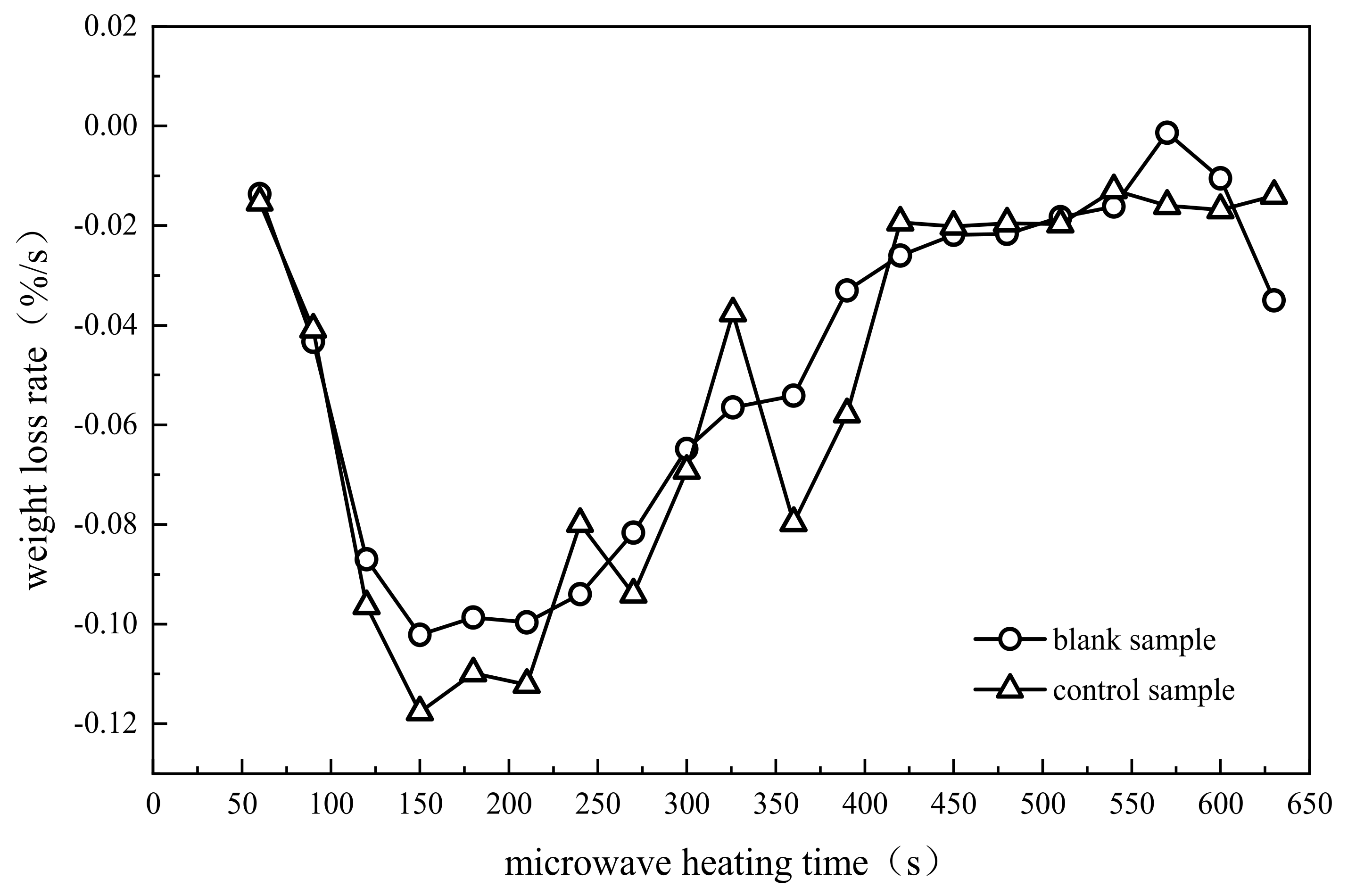
3.2. Stage Division of Pyrolysis Process

According to the comprehensive analysis of the thermogravimetric curve, heating rate curve and weight loss rate curve, the pyrolysis process of oily sludge can be divided into three stages. The first stage, the rapid heating and water evaporation stage (20~150 °C), is named stage I. The second stage, the light component evaporation stage (150~240 °C), is named stage II. The third stage, the primary cracking stage of the heavy components (240~300 °C) is named stage III.
According to the experimental results in Section 3.1, the microwave heating time of the control sample is less than the microwave heating time of the blank sample at the same pyrolysis temperature. To further analyze the strengthening effect of magnetic nanoparticles at each stage on the microwave pyrolysis of oily sludge, the data from the three pyrolysis stages of oily sludge are given in Table 1. Among these pyrolysis stages, the heating time refers to the time used for microwave pyrolysis within the temperature range. The percentage reduction in time refers to the ratio of the heating time difference between the blank and control samples relative to the heating time of the blank sample in the same stage, which is conducive to the analysis of the time utilization efficiency of pyrolysis for oily sludge with magnetic nanoparticles added. Output energy refers to the energy output by microwave heating within a certain period of time, that is, the energy consumed in the pyrolysis of oily sludge. Output energy is calculated by the Formula W = Pt. W is the total energy output by microwaves, P is the microwave output power, and t is the microwave heating time. The energy saving percentage refers to the ratio of the output energy difference between the blank sample and the control samples to the output energy of the blank sample, which is helpful to analyze the energy utilization rate of oily sludge during microwave pyrolysis enhanced by magnetic nanoparticles.
Table 1 shows that the heating time and output energy of the two samples used in stage I are greater than the heating time and output energy of the samples in stage II because in the rapid heating and water evaporation stages, water molecules easily absorb microwave energy and output the microwave energy in the form of heat energy, also reflecting the characteristics of microwave heating, and every part of the heated material inside is all the internal heat sources when microwave heating occurs. Compared with conventional heat transfer, the microwave heating method is faster and more selective. The shortened time and saved energy of microwave pyrolysis of the control sample in stage II are greater, because the light components start to evaporate in this stage, and the addition of magnetic nanoparticles strengthens the microwave absorption and improves the efficiency of microwave absorption. Namely, when reaching the same pyrolysis temperature under the same reaction conditions, the time of the control sample used is shorter, and the energy consumption needed is less, both heating time and energy consumption were saved by 27.8%. In stage III, the heavy components start to primarily crack, and the microwave heating time and saved energy of the control sample are reduced by 52.2% at most, which fully indicates that magnetic nanoparticles could strengthen the microwave pyrolysis of oily sludge.

3.3. Characteristic Analysis of Pyrolysis Products
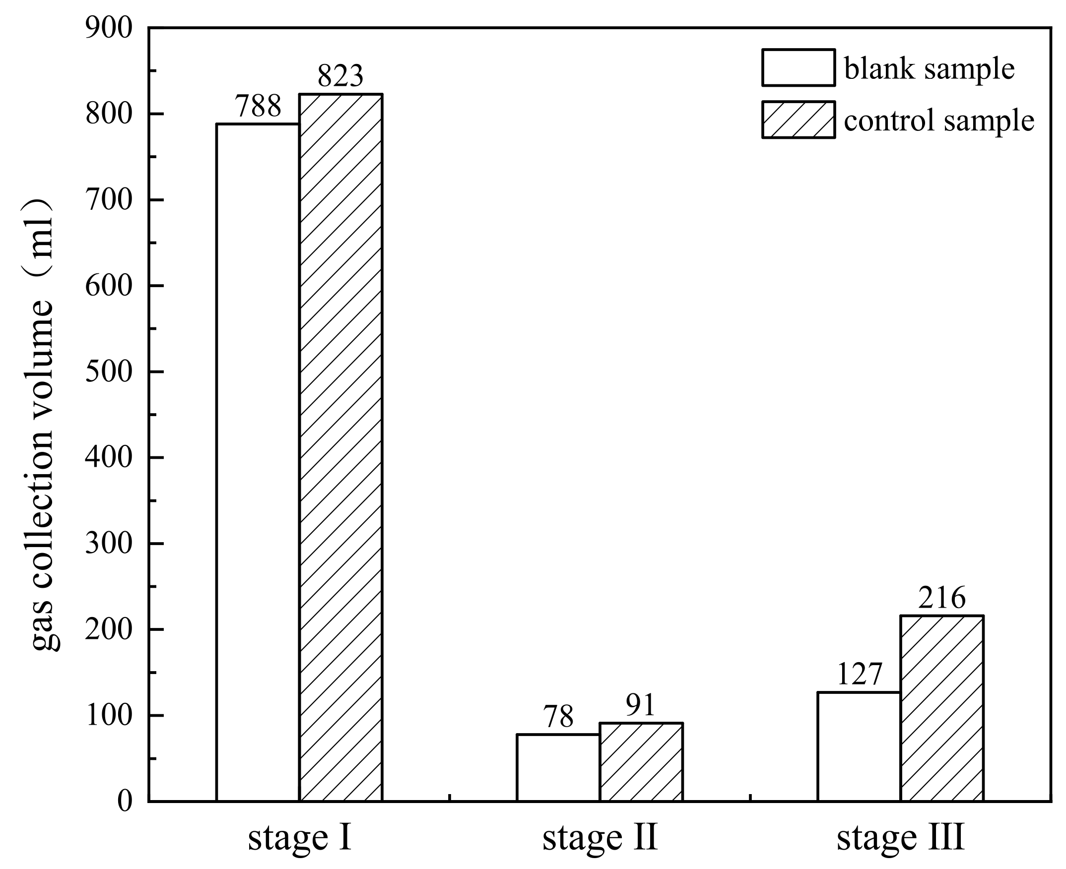
To explore the process routine of magnetic nanoparticle-enhanced microwave pyrolysis of oily sludge from the perspective of kinetics analysis, the pyrolysis products of the three stages were collected and analyzed by a pyrolysis product staged collection device in this section. The pyrolysis products of oily sludge include mainly gas and liquid products, and the liquid product includes oil and water. The volume of the gas products is measured by the drainage method with the help of a measuring cylinder. The collections of gas and liquid products were extracted by a gas collecting needle tube and a liquid collecting needle tube, respectively. The volumes of oil and water were measured after standing. Finally, the gas product and the oil component in the liquid product were analyzed by gas chromatography.

3.3.1. Gas Products

The gas collection volumes of oily sludge in three stages of microwave pyrolysis are shown in Figure 7.
Figure 7 shows that, compared with the other two stages, the gas collection volume in stage I is the largest, and there is no significant difference between the blank and control samples in this stage. The gas volume of the control sample was 823 mL, and the gas volume of the blank sample was 788 mL, increasing by 4.44%, possibly because the heating rate of oily sludge in stage I is higher than the heating rate of oily sludge in other stages. In this stage, microwave pyrolysis produces mainly a large amount of water vapor. Water vapor continues to run into the condenser tube, and much of the uncondensed gas enters the gas collector, resulting in an increase in gas collection. In addition, nitrogen purging before the experiment starts may lead to residual nitrogen in the device, which is also a possible reason for the phenomenon. In addition, there was little difference in gas collection between the control and blank samples, possibly due to the small difference in final pyrolysis temperature, heating rate and weight loss rate between the two samples in stage I. With the increase in temperature in stage II, the gas collection volume of the control sample is 91 mL, and the gas collection volume of the blank sample is 78 mL, increasing by 16.67%. In stage III, the production of uncondensed gas increased, and the color of the condensed oil droplets deepened. A total of 216 mL of gas was collected in the control sample, and 127 mL of gas was collected in the blank sample. The gas increment ratio reached the maximum of 70.1% because magnetic nanoparticles intensify the pyrolysis of oily sludge, generating more gas.
The experimental gases collected from the two samples in stage II and stage III were injected into the gas chromatograph using a gas-collecting syringe for component detection. The volume fraction of each gas phase component in each stage was calculated by the area normalization method, and the result is shown in Table 2.
Table 2 shows that the experimental results of the two samples in stage II and stage III show that the volume fraction of H2 in the gas product increases with increasing pyrolysis temperature. The volume fraction of H2 of the blank sample increases from 0 in stage II to 7.6% in stage III. The increment in the control sample is more obvious, from 3% to 18%. In the two samples, the content of CO2 and CH4 increased, and the volume fractions of N2+O2 and CxHy hydrocarbons decreased. In stage II, the differences in the volume fraction of each component between the control and blank samples are almost smaller than the differences in the volume fraction in stage III, possibly because this stage consists mainly of the volatilization of light components, and the magnetic nanoparticle begins to gradually make its mark. The volume fractions of H2, CO2, CH4 and CxHy hydrocarbons of the control sample in stage III changed significantly compared with the corresponding volume fractions of the blank sample. The volume fraction of H2 experiences the greatest change, with a difference of 10.4% between the two samples. Comprehensive analysis shows that the reaction process in the cracking stage of the heavy component is more complex. The addition of magnetic nanoparticles enhances the degree of pyrolysis of oily sludge, improves the conversion of H2, and accelerates the pyrolysis of the heavy fraction into the light gas fraction.

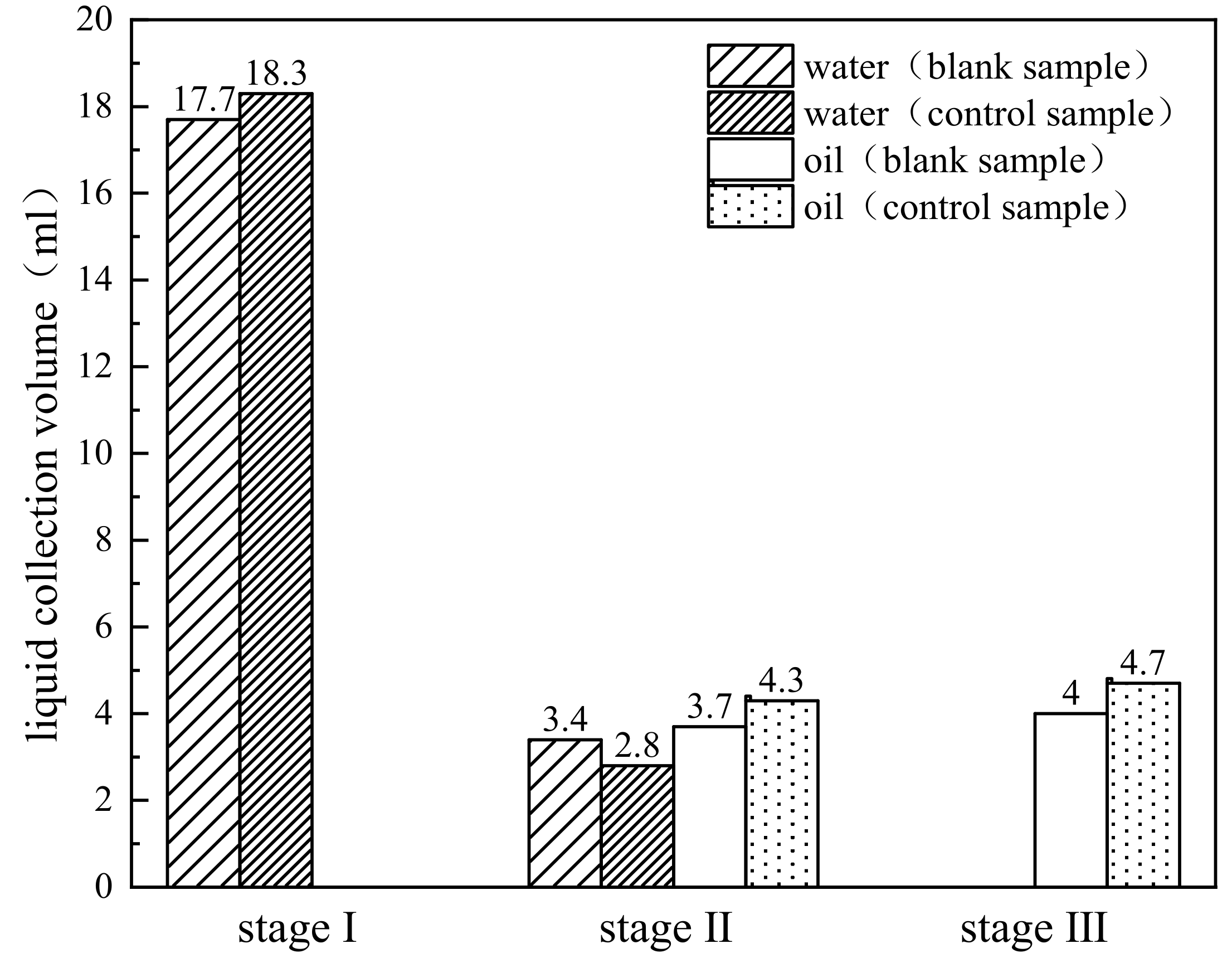
3.3.2. Liquid Products

The liquid collection volumes in the three stages of microwave pyrolysis are shown in Figure 8.
Figure 8 shows that the liquid collection volumes of the two samples in stage I are much higher than the liquid collection volumes in the other two stages, and the liquid product is water because in stage I, the water from oily sludge evaporates into a large volume of water vapor, and water vapor condenses into water droplets through the condenser. The liquid collected in the experiments eventually becomes a colorless transparent liquid, which also proves this point. Finally, the liquid collection volume of the control sample was 18.3 mL, and the liquid collection volume of the blank sample was 17.7 mL, increasing by 3.4%. With the further increase in temperature, the experiment goes into stage II. At this stage, we observed that the high-temperature flue gas is condensed into oil droplets with a light yellow color through the condenser tube. After standing, the liquid exhibits a stratification phenomenon. The lower end is a colorless transparent liquid, and the upper end shows a light yellow oil. Finally, the water volume collected in the control and blank samples was 2.8 mL and 3.4 mL, respectively, and the oil was 4.3 mL and 3.7 mL, respectively. Compared with the blank sample, the amount of water collected in the control sample decreased, but the amount of oil increased. If the amount of water collected from the control sample in stage I and stage II were added, the combined amounts were equal to 21.1 mL as is the blank sample, indicating that the addition of magnetic nanoparticles does not change the type of reaction products and accelerates the reaction process. In stage III, the oily sludge of the two samples is further deeply cracked to generate stronger yellowish-brown smoke. After condensation, yellowish-brown oil droplets without water were collected. The oil collections of the control and blank samples were 4.7 mL and 4 mL, respectively. The control sample was 0.7 mL more than the blank sample, with an increase of 17.5%. The control sample in stage II and stage III collects a total of 9.0 mL of oil, while the blank sample collects 7.7 mL of oil, increasing by 16.88%. The addition of magnetic nonZnFe2O4 particles accelerates the pyrolysis reaction and enables more heavy components to participate in the reaction in a microwave pyrolysis environment.
The oil collected from the two samples in stage II and stage III was rapidly injected into the chromatograph through a microsampling syringe. According to the measurement results, the oil is divided into three ranges by the carbon content: C4~C12, C13~C18, and C18+. The volume fractions of liquid components of each sample in the two stages obtained are shown in Table 3.
Table 3 shows that the variations in the volume fraction of components in different ranges in each stage of the two samples are similar; that is, the content of C4~C12 decreases slightly, the content of C13~C18 decreases significantly, and the content of C18+ increases as the reaction proceeds. In particular, the content of C13~C18 in the control sample decreases from 47.7% in stage II to 38.8% in stage III and the content of C13~C18 in the blank sample decreases from 47.6% in stage II to 38.2% in stage III. The content of C18+ in the control sample increases from 25.8% in stage II to 36.3% in stage III, and the content of C18+ in the blank sample increases from 28.1% in stage II to 40.4% in stage III, indicating that as the experimental process changes from light component evaporation to heavy component cracking, the reaction experiences the transformation from simple reaction of small molecules to complex pyrolysis of macromolecules. In stage III, compared with the blank sample, the content of C4~C12 in the control sample increased by 3.5%, while the content of C13~C18 increased only from 38.2% to 38.8%. In contrast, the content of C18+ in the control sample decreased by 4.1% compared with the content of C18+ in the blank sample. This phenomenon demonstrates that the addition of magnetic nanoparticles decreases the heavy components in the final pyrolysis products and increases the light components, indicating that the magnetic nanoparticles can decompose macromolecules with long carbon chains (heavy components) into small molecules with short carbon chains (light components).

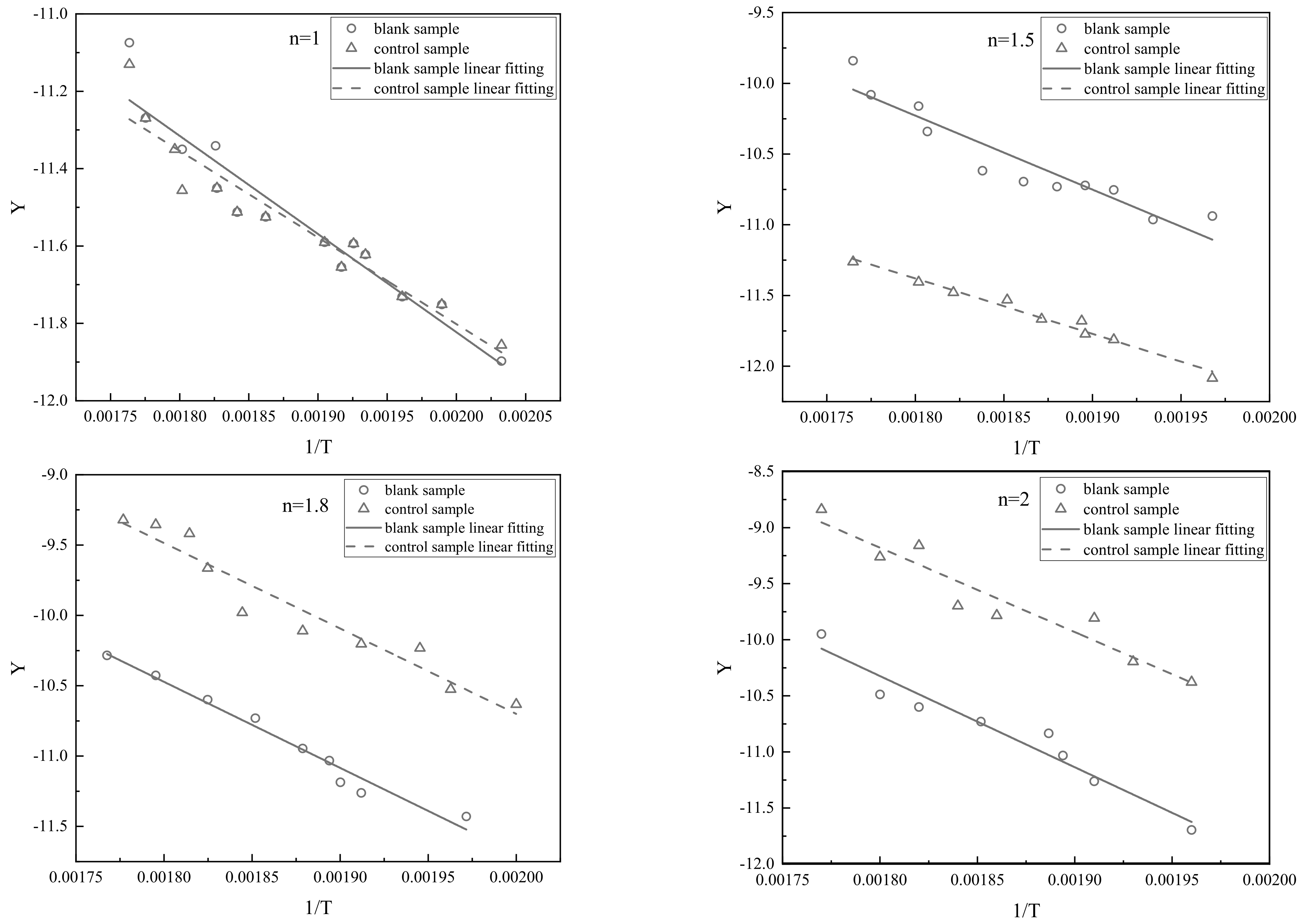
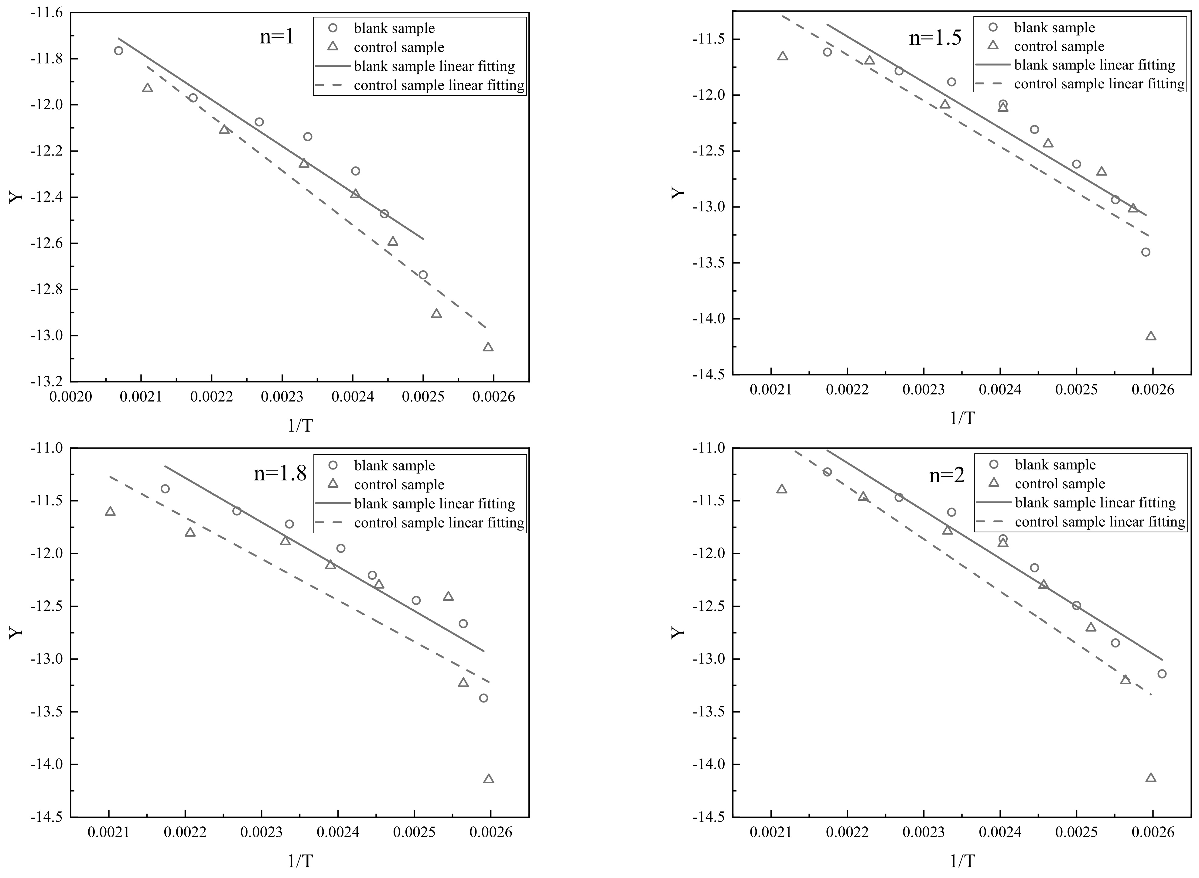
3.4. Reaction Kinetics Analysis

In this section, according to the reaction kinetics equation in Section 2.4, kinetics simulation analysis of magnetic particle-enhanced microwave pyrolysis of oily sludge is carried out. The assumption of kinetics simulation is the Arrhenius equation, which requires that the experimental data satisfy a certain linear correlation. Therefore, the kinetics equations of stage II and stage III in the reaction process of microwave pyrolysis for oily sludge are studied according to Section 3.1.
First, according to the Arrhenius law and the characteristics of microwave pyrolysis products, the reaction mechanism function is determined and solved by the Coats-Redfern empirical integration method. Second, the reaction order of the mechanism function is assumed and determined by the correlation coefficient, and then linear regression is performed using the experimental data. It should be noted that β is approximately the slope of a linear fitting of temperature versus time for each stage in Equation (10). We assume that T in (1 − 2RT/E) is the average temperature in each stage. Finally, the kinetic activation energy and pre-exponential factor of each stage are calculated, and the reaction kinetics equation is determined.

3.4.1. Kinetics Simulation in Stage II

The linear fitting curves of Y and 1/T of the blank and control samples in stage II under four reaction orders n = 1, 1.5, 1.8, and 2 are shown in Figure 9.
The linear fitting equations of the two samples in stage II are shown in Table 4.
The fitting formula in Table 4 shows that the linear fitting formula for the blank sample in stage II has the highest correlation coefficient R2 = 0.9512 when the reaction order n = 1.8, indicating that its fitting effect is the best. Therefore, the mechanism function of the chemical reaction can be described as f(α) = (1 − α)1.8. The reaction activation energy of the pyrolysis process in stage II is calculated to be 22.44 kJ/mol, and the pre-exponential factor is 11.34 s−1. Therefore, the chemical reaction mechanism function of the blank sample in stage II is:
d α d T = 40 . 5 exp ( 22 . 44 × 10 3 R T ) ( 1 - α ) 1 . 8
For the control sample in stage II, when the reaction order n = 1, the linear fitting formula has the highest correlation coefficient R2 = 0.9589, and the fitting effect is the best. Therefore, the mechanism function of the chemical reaction is f(α) = 1 − α. The reaction activation energy of the pyrolysis process in stage II is calculated to be 14.21 kJ/mol, and the pre-exponential factor is 4.48 s−1. The chemical reaction mechanism function of the control sample in stage II is
d α d T = 8 . 3 exp ( 14 . 21 × 10 3 R T ) ( 1 - α )

3.4.2. Kinetics Simulation in Stage III

The linear fitting curves of Y and 1/T of the blank and control samples in stage III under four reaction orders n = 1, 1.5, 1.8, and 2 are shown in Figure 10.
The linear fitting equations of the two samples in stage III are shown in Table 5.
Table 5 shows that the linear fitting formulas of the blank sample and control sample have the highest correlation coefficients R2 = 0.9658 and 0.9738, respectively, when the chemical reaction order n = 1.8 and 1.5 in stage III. At the moment, the mechanism functions of the chemical reaction for the blank and control samples can be described as f(α) = (1 − α)1.8 and f(α) = (1 − α)1.5, respectively. Thus, the reaction activation energy of the blank sample in stage III is calculated to be 51.27 kJ/mol, and the pre-exponential Factor A is 755.64 s−1. The reaction activation energy of the control sample is 32.56 kJ/mol, and the pre-exponential Factor A is 65.05 s−1. Therefore, the chemical reaction mechanism function of the blank sample in stage III is:
d α d T = 3285 . 4 exp ( 51 . 27 × 10 3 R T ) ( 1 - α ) 1 . 8
The chemical reaction mechanism function of the control sample in stage III is:
d α d T = 244 . 3 exp ( 32 . 56 × 10 3 R T ) ( 1 - α ) 1 . 5
The response parameters of the blank and control samples in the two stages are shown in Table 6.
Table 6 shows that for the reaction order, the control sample (n = 1) in stage II is lower than the blank sample (n = 1.8), and the same is true in stage III. The apparent activation energy of the blank sample in stage II is 22.44 kJ/mol, the control sample is 14.21 kJ/mol, reducing by 36.68%. The apparent activation energy of the control sample in stage III decreased by 36.49% compared with the apparent activation energy of the blank sample. For the pre-exponential factor, the blank and control samples in stage II are 11.34 s−1 and 4.48 s−1, respectively. The pre-exponential factor of the control sample in stage II was 60.49% lower than the pre-exponential factor of the blank sample, while the pre-exponential factor of the control sample in stage III was 91.39% lower than the pre-exponential factor of the blank sample. In conclusion, the optimal reaction order, apparent activation energy and pre-exponential factor of the control sample are lower than the optimal reaction order, apparent activation energy and pre-exponential factor of the blank sample in stage II and stage III. The magnetic nanoparticles have been fully proven to have good catalytic activity. On the one hand, magnetic nanoparticles as microwave absorbents enhance the nonthermal effect in the process of microwave pyrolysis for oily sludge. On the other hand, magnetic nanoparticles have high coercivity, low Curie temperature, superparamagnetism, and high magnetic susceptibility, coupled with their small size effect and surface effect, which can provide good catalytic activity. These properties of the magnetic nanoparticles also explain why the pyrolysis temperature, heating rate, weight loss rate, gas and liquid production rate of the control sample are better than the pyrolysis temperature, heating rate, weight loss rate, gas and liquid production rate of the blank sample.
The experimental results also show that for the control sample, the apparent activation energy required for the reaction and the pre-exponential factor in the reaction process increase with increasing pyrolysis temperature because when the temperature is low, side chains with poor thermal stability and functional groups with strong activity are easy to carry out during the pyrolysis reaction. Reaction of the side chains presented a small apparent activation energy and pre-exponential factor. With the progress of the reaction, the long-chain alkanes in oily sludge began to decompose, and the functional groups with weak activity began to participate. This process needs to be carried out at high temperature, which increases the apparent activation energy and pre-exponential factor [45], reflecting the dynamic compensation effect of oily sludge in the pyrolysis process [46,47].

4. Conclusions

In this paper, the pyrolysis process of oily sludge treated by microwaves was intensively studied from two aspects: pyrolysis product characteristics and kinetic equations using a self-established microwave thermogravimetric reaction and pyrolysis product staged collection devices. The research results will be of great significance for strengthening the effect of microwaves, improving pyrolysis efficiency, and realizing the goal of resource utilization, reduction and harmlessness for oily sludge. The main conclusions are as follows.
(1) Studies with and without magnetic nanoparticles confirmed that the addition of magnetic ZnFe2O4 nanoparticles did not change the microwave pyrolysis process of oily sludge and could improve the pyrolysis efficiency. According to the thermogravimetric curves, the pyrolysis process of oily sludge was divided into three stages: rapid heating and water evaporation stage (20~150 °C), light component evaporation stage (150~240 °C) and heavy component cracking stage (240~300 °C).
(2) The analysis of pyrolysis product characteristics found that the production of H2, CO2 and CH4 in the two samples increased with increasing pyrolysis temperature. The production of light components in the control sample was greater, and the increase in the gas volume fraction was more obvious. As the reaction proceeded, the control sample produced more oil, in which the content of heavy oil component C18+ decreased relatively, the content of C4~C12 increased relatively, and the content of C13~C18 did not change significantly.
(3) According to the thermogravimetric curves, the kinetics simulation of the oily sludge pyrolysis process was carried out by Arrhenius law. The kinetic equations of the blank and control samples in stage II and stage III, as well as their activation energy and pre-exponential factor, were obtained. Through analysis, the apparent activation energy of the control sample was found to be lower than the apparent activation energy of the blank sample in the above two stages, which makes pyrolysis easier.

Author Contributions

Conceptualization, H.Q. (Hongyuan Qi); methodology, Z.W. and Y.W.; formal analysis, Y.Y. and J.H.; resources, H.J. and H.Q. (Hongxin Qi); writing—review and editing, H.Q. (Hongyuan Qi), Z.W. and Y.Y.; project administration, H.J. and H.Q. (Hongyuan Qi); funding acquisition, H.Q. (Hongyuan Qi). All authors have read and agreed to the published version of the manuscript.

Funding

Natural Science Basic Research Program of Shaanxi (Program No. 2019JQ-819) and Scientific Research Program Funded by Shaanxi Provincial Education Department (Program No. 20JS118).

Institutional Review Board Statement

Not applicable.

Informed Consent Statement

Not applicable.

Data Availability Statement

Not applicable.

Acknowledgments

This work was supported by the Natural Science Basic Research Program of Shaanxi (Program No. 2019JQ-819) and Scientific Research Program Funded by Shaanxi Provincial Education Department (Program No. 20JS118).

Conflicts of Interest

The authors declare no conflict of interest.

References

  1. Wang, Z.; Gong, Z.; Wang, Z.; Li, X.; Chu, Z. Application and Development of Pyrolysis Technology in Petroleum Oily Sludge Treatment. Environ. Eng. Res. 2020, 26, 190460. [Google Scholar] [CrossRef]
  2. Liu, Y.; Yu, H.; Jiang, Z.; Song, Y.; Fang, J. Microwave Pyrolysis of Oily Sludge Under Different Control Modes. J. Hazard. Mater. 2021, 416, 125887. [Google Scholar] [CrossRef] [PubMed]
  3. Wang, C.; Wang, W.; Lin, L.; Zhang, F.; Zhao, X. A Stepwise Microwave Synergistic Pyrolysis Approach to Produce Sludge-Based Biochars: Feasibility Study Simulated by Laboratory Experiments. Fuel 2020, 272, 117628. [Google Scholar] [CrossRef]
  4. Qin, L.; Han, J.; Xiang, H.; Zhan, Y.; Fei, Y. Recovery of Energy and Iron from Oily Sludge Pyrolysis in a Fluidized Bed Reactor. J. Environ. Manag. 2015, 154, 177–182. [Google Scholar] [CrossRef]
  5. Hu, Z.Y. Experimental Study on Low Temperature Thermal Pyrolysis of Oily Sludge in Tahe Oilfield. Environ. Prot. Oil Gas Fields 2015, 25, 9–11. [Google Scholar]
  6. Wu, Z.; Yin, J.; Wang, J. Study on the Role of Microwave Absorbent in Microwave Pyrolysis of Oily Sludge. Int. Core J. Eng. 2020, 6, 417–420. [Google Scholar]
  7. Cheng, S.; Wang, Y.; Fumitake, T.; Kouji, T.; Li, A.; Kunio, Y. Effect of Steam and Oil Sludge Ash Additive on the Products of Oil Sludge Pyrolysis. Appl. Energy 2017, 185, 146–157. [Google Scholar] [CrossRef]
  8. Cheng, S.; Takahashi, F.; Gao, N.; Yoshikawa, K.; Li, A. Evaluation of Oil Sludge Ash as a Solid Heat Carrier in the Pyrolysis Process of Oil Sludge for Oil Production. Energy Fuels 2016, 30, 5970–5979. [Google Scholar] [CrossRef]
  9. Lv, X.; Song, Z.; Yu, J.; Su, Y.; Wang, W. Study on the Demulsification of Refinery Oily Sludge Enhanced by Microwave Irradiation. Fuel 2020, 279, 118417. [Google Scholar] [CrossRef]
  10. Cavalcante, T.; Funcia, E.; Gut, J. Inactivation of Polyphenol Oxidase by Microwave and Conventional Heating: Investigation of Thermal and Non-Thermal Effects of Focused Microwaves. Food Chem. 2020, 340, 127911. [Google Scholar] [CrossRef]
  11. Luyao, W.; Dong, M.; Lu, L. ‘Heat Effect’ or ‘Non-Heat Effect’-Microwave Heating Reaction Mechanism. Chemistry 2013, 76, 698–703. [Google Scholar]
  12. Kappe, C.O.; Stadler, A.; Dallinger, D. Microwaves in Organic and Medicinal Chemistry. Weinh. Wiley-VCH 2012, 25, 543–648. [Google Scholar]
  13. Robinson, J.; Kingman, S.; Irvine, D.; Licence, P.; Smith, A.; Dimitrakis, G.; Obermayer, D.; Kappe, C.O. Electromagnetic Simulations of Microwave Heating Experiments Using Reaction Vessels Made Out of Silicon Carbide. Phys. Chem. Chem. Phys. 2010, 12, 10793–10800. [Google Scholar] [CrossRef]
  14. Yu, Y.; Yang, C.; Li, J.; Zhu, Y.; Yan, Z.; Zhang, H. Screening of Inexpensive and Efficient Catalyst for Microwave-Assisted Pyrolysis of Ship Oil Sludge. J. Anal. Appl. Pyrolysis 2020, 152, 104971. [Google Scholar] [CrossRef]
  15. Lee, C.L.; Tsai, C.H.; Jou, C.J.G. Energy and Resource Utilization of Refining Industry Oil Sludge by Microwave Treatment. Sustainability 2020, 12, 6862. [Google Scholar] [CrossRef]
  16. Su, B.; Huang, L.; Li, S.; Ding, L.; Liu, B.; Zhang, A. Chemical–Microwave–Ultrasonic Compound Conditioning Treatment of Highly-Emulsified Oily Sludge in Gas Fields. Nat. Gas Ind. B 2019, 6, 412–418. [Google Scholar] [CrossRef]
  17. Salema, A.A.; Yeow, Y.K.; Ishaque, K.; Ani, F.N.; Afzal, M.T.; Hassan, A. Dielectric Properties and Microwave Heating of Oil Palm Biomass and Biochar. Ind. Crops Prod. 2013, 50, 366–374. [Google Scholar] [CrossRef]
  18. Wan, G.; Tian, Y.; Zhang, L.; Fang, L. Experimental Study on Reaction Conditions of Activated Carbon-Assisted Microwave Pyrolysis of Sludge. Ecol. Environ. 2010, 19, 2182–2186. [Google Scholar]
  19. Tian, Y.; Gong, Z.; Wu, X.; Chen, H.; Zuo, W. The Influence Factors of H2S Release from Sewage Sludge Microwave Pyrolysis Process. Environ. Pollut. Amp 2013, 35, 7–10. [Google Scholar]
  20. Wang, T.; Hu, J.; Xia, L.; Qu, X. Pyrolysis of Sewage Sludge by Microwave Radiation. J. Shenyang Univ. Nat. Sci. Ed. 2008, 24, 662–666. [Google Scholar]
  21. Chen, Y.R. Microwave Pyrolysis of Oily Sludge with Activated Carbon. Environ. Technol. Lett. 2016, 37, 3139–3145. [Google Scholar] [CrossRef] [PubMed]
  22. Domínguez, A.; Menéndez, J.A.; Fernández, Y.; Pis, J.J.; Nabais, J.M.V.; Carrott, P.J.M.; Carrott, M.M.L.R. Conventional and Microwave Induced Pyrolysis of Coffee Hulls for the Production of a Hydrogen Rich Fuel Gas. J. Anal. Appl. Pyrolysis 2007, 79, 128–135. [Google Scholar] [CrossRef]
  23. Domínguez, A.; Menéndez, J.A.; Inguanzo, M.; Pís, J.J. Production of Bio-Fuels by High Temperature Pyrolysis of Sewage Sludge Using Conventional and Microwave Heating. Bioresour. Technol. 2006, 97, 1185–1193. [Google Scholar] [CrossRef] [PubMed]
  24. Menendez, J.A.; Dominguez, A.; Inguanzo, M.; Pis, J.J. Microwave-Induced Drying, Pyrolysis and Gasification (MWDPG) of Sewage Sludge: Vitrification of the Solid Residue. J. Anal. Appl. Pyrolysis 2005, 74, 406–412. [Google Scholar] [CrossRef]
  25. Menendez, J.A.; Inguanzo, M.; Pis, J.J. Microwave-Induced Pyrolysis of Sewage Sludge. Water Res. 2002, 36, 3261–3264. [Google Scholar] [CrossRef]
  26. Shie, J.L.; Lin, J.P.; Chang, C.Y.; Lee, D.J.; Wu, C.H. Pyrolysis of Oil Sludge with Additives of Sodium and Potassium Compounds. Resour. Conserv. Recycl. 2003, 39, 51–64. [Google Scholar] [CrossRef]
  27. Namazi, A.B.; Allen, D.G.; Jia, C.Q. Microwave-Assisted Pyrolysis and Activation of Pulp Mill Sludge. Biomass Bioenergy 2015, 73, 217–224. [Google Scholar] [CrossRef]
  28. Li, P.; Shi, X.; Song, J.; Fang, S.; Bai, J.; Chang, C. Research Progress of Biomass Microwave Catalytic Pyrolysis for Preparation of High Value-Added Products. Chem. Ind. Eng. Prog. 2021, 41, 1–16. [Google Scholar]
  29. Mario, R.H.; Marshall, W.D. Reduction of Hexavalent Chromium Mediated by Micro- and Nano-Sized Mixed Metallic Particles. J. Hazard. Mater. 2009, 169, 1081–1087. [Google Scholar]
  30. Ali, N.; Zhang, B.; Zhang, H.; Zaman, W.; Li, X.; Li, W.; Zhang, Q. Interfacially Active and Magnetically Responsive Composite Nanoparticles with Raspberry Like Structure; Synthesis and Its Applications for Heavy Crude Oil/Water Separation. Colloids Surf. A Physicochem. Eng. Asp. 2015, 472, 38–49. [Google Scholar] [CrossRef]
  31. Chai, L.; Wang, Q.; Zhou, N.; Du, Y.; Zeng, X.; Zhou, S.; He, Q.; Wu, G. In-Situ Growth of Core-Shell ZnFe2O4 @ Porous Hollow Carbon Microspheres as An Efficient Microwave Absorber. J. Colloid Interface Sci. 2021, 581, 475–484. [Google Scholar] [CrossRef] [PubMed]
  32. Wu, S.; Ge, R.; Lu, M.; Xu, R.; Zhang, Z. Graphene-Based Nano-Materials for Lithium–Sulfur Battery and Sodium-Ion Battery. Nano Energy 2015, 15, 379–405. [Google Scholar] [CrossRef]
  33. Wongkaew, N.; Simsek, M.; Griesche, C.; Baeumner, A.J. Functional Nanomaterials and Nanostructures Enhancing Electrochemical Biosensors and Lab-on-a-Chip Performances: Recent Progress, Applications, and Future Perspective. Chem. Rev. 2019, 119, 120–194. [Google Scholar] [CrossRef] [PubMed]
  34. Prashanth, P.F.; Burada, S.; Vinu, R.; Lavanya, M.; Prabu, V.R. Production of Diesel Range Hydrocarbons from Crude Oil Sludge via Microwave-Assisted Pyrolysis and Catalytic Upgradation. Process Saf. Environ. Prot. 2020, 146, 383–395. [Google Scholar] [CrossRef]
  35. Saitov, R.I.; Abdeev, R.G.; Fatykhov, M.A.; Abdeev, E.R.; Khasanova, A.F. Development of Energy-resource-efficient Equipment and Technologies of Environmentally Safe Microwave Processing of Oil Sludges. KnE Mater. Sci. 2020, 9, 1683–1687. [Google Scholar] [CrossRef]
  36. Nariya, P.; Das, M.; Shukla, F.; Thakore, S. Synthesis of Magnetic Silver Cyclodextrin Nanocomposite as Catalyst for Reduction of Nitro Aromatics and Organic Dyes. J. Mol. Liq. 2020, 300, 112279. [Google Scholar] [CrossRef]
  37. Coutinho, T.C.; Malafatti, J.; Paris, E.C.; Tardioli, P.W.; Farinas, C.S. Hydroxyapatite-CoFe2O4 Magnetic Nanoparticle Composites for Industrial Enzyme Immobilization, Use, and Recovery. ACS Appl. Nano Mater. 2020, 3, 12334–12345. [Google Scholar] [CrossRef]
  38. Song, W.; Liu, J.G.; Nie, Y.F. Influencing Factors and Product Property of Low Temperature Pyrolysis of Oil Sludge. China Environ. Sci. 2008, 28, 340–344. [Google Scholar]
  39. Shie, J.L.; Chang, C.Y.; Lin, J.P.; Wu, C.H.; Lee, D.J. Resources Recovery of Oil Sludge by Pyrolysis: Kinetics Study. J. Chem. Technol. Biotechnol. 2000, 75, 443–450. [Google Scholar] [CrossRef]
  40. Wu, Z. Mechanism of Magnetic Nanoparticles Enhanced Microwave Pyrolysis of Oily Sludge. Master’s Thesis, Xi’an Shiyou University, Xi’an, China, 2021. [Google Scholar]
  41. Tamizhdurai, P.; Krishnasamy, S.; Nambi, I. Process Optimization for the Recovery of Oil from Tank Bottom Sludge Using Microwave Pyrolysis. Process Saf. Environ. Prot. 2020, 148, 392–399. [Google Scholar]
  42. Chiarioni, A.; Reverberi, A.P.; Fabiano, B.; Dovi, V.G. An Improved Model of an ASR Pyrolysis Reactor for Energy Recovery. Energy 2006, 31, 2460–2468. [Google Scholar] [CrossRef]
  43. Narnaware, S.L.; Panwar, N.L. Kinetic Study on Pyrolysis of Mustard Stalk Using Thermogravimetric Analysis. Bioresour. Technol. Rep. 2022, 17, 100942. [Google Scholar] [CrossRef]
  44. Wang, W.F.; Li, G.; Yong, X.Y.; Liu, P.; Zhang, X.F. The Features of Microwave Thermal Conversion of Oil Sludge. Appl. Mech. Mater. 2012, 2047, 788–791. [Google Scholar] [CrossRef]
  45. Wen, Y.; Xie, Y.; Jiang, C.; Li, W.; Hou, Y. Products Distribution and Interaction Mechanism During Co-Pyrolysis of Rice Husk and Oily Sludge by Experiments and Reaction Force Field Simulation. Bioresour. Technol. 2021, 329, 124822. [Google Scholar] [CrossRef]
  46. Sergey, V. Determining Preexponential Factor in Model-Free Kinetic Methods: How and Why? Molecules 2021, 26, 3077. [Google Scholar]
  47. Qi, Y.; Ge, B.; Cao, Q.; Xi, F.; Shi, X.; Si, Y.; Wang, X.; Gao, B.; Yue, Q.; Xu, X. Application of Sectionalized Single-Step Reaction Approach (SSRA) and Distributed Activation Energy Model (DAEM) on the Pyrolysis Kinetics Model of Upstream Oily Sludge: Construction Procedure and Data Reproducibility Comparison. Sci. Total Environ. 2021, 774, 145751. [Google Scholar] [CrossRef]
Figure 1. Schematic diagram of the microwave thermogravimetric device.
Energies 15 01254 g001
Figure 2. Schematic diagram of the pyrolysis product staged collection device.
Energies 15 01254 g002
Figure 3. Curves of microwave pyrolysis temperature over time.
Energies 15 01254 g003
Figure 4. Curves of microwave pyrolysis heating rate over time.
Energies 15 01254 g004
Figure 5. Curves of the weight of oily sludge during microwave pyrolysis over time.
Energies 15 01254 g005
Figure 6. Curves of the weight loss rate of oily sludge during microwave pyrolysis over time.
Energies 15 01254 g006
Figure 7. Gas collection volumes in three stages of microwave pyrolysis.
Energies 15 01254 g007
Figure 8. Liquid collection volumes in three stages of microwave pyrolysis.
Energies 15 01254 g008
Figure 9. Linear fitting of microwave pyrolysis in stage II with different reaction orders.
Energies 15 01254 g009
Figure 10. Linear fitting of microwave pyrolysis in stage III with different reaction orders.
Energies 15 01254 g010
Table 1. Pyrolysis staged data of oily sludge.
Phase and Time of ReactionRapid Heating and Water Evaporation
(Stage I)
Light Component Evaporation
(Stage II)
Primary Cracking of Heavy Component
(Stage III)
Temperature range (°C)20~150150~240240~300
Heating time of blank sample (s)320180460
Heating time of control sample (s)280130220
Percentage reduction in time12.5%27.8%52.2%
Output energy of blank sample (kJ)256144368
Output energy of control sample (kJ)224104176
Energy saving percentage12.5%27.8%52.2%
Table 2. Volume fractions of gas components in different stages of microwave pyrolysis.
ComponentStage II (Volume Fraction %)Stage III (Volume Fraction %)
Blank SampleControl SampleBlank SampleControl Sample
H2037.618
N2 + O226.824.311.410.2
CO248.644.752.247.2
CH43.778.115
C2H67.299.35.4
CXHY13.71211.54.2
Table 3. Volume fractions of liquid components in two stages of microwave pyrolysis.
ComponentStage II (Volume Fraction %)Stage III (Volume Fraction %)
Blank SampleControl SampleBlank SampleControl Sample
C4~C1224.326.521.424.9
C13~C1847.647.738.238.8
C18+28.125.840.436.3
Table 4. Linear fitting equations of the two samples under different reaction orders in stage II.
Reaction Order nBlank SampleControl Sample
Fitting EquationCorrelation Coefficient R2Fitting EquationCorrelation Coefficient R2
1Y = −1959.67X − 7.670.9498Y = −1709.21X − 8.020.9589
1.5Y = −1836.99X − 7.680.9428Y = −2356.19X − 6.870.9283
1.8Y = −2699.03X − 4.20.9512Y = −2908.36X − 5.330.8976
2Y = −3840.13X − 2.930.9257Y = −3820.48X − 3.050.8375
Table 5. Linear fitting equations of the two samples under different reaction orders in stage III.
Reaction Order nBlank SampleControl Sample
Fitting EquationCorrelation Coefficient R2Fitting EquationCorrelation Coefficient R2
1Y = −2566.95X − 6.690.9028Y = −2239.78X − 7.320.9067
1.5Y = −4687.77X − 1.810.8905Y = −3917.03X − 3.020.9738
1.8Y = −6167.03X − 0.630.9658Y = −6202.84X + 1.740.9161
2Y = −8018.97X + 4.100.9308Y = −6696.26X + 3.030.8328
Table 6. Reaction parameters in two stages of microwave pyrolysis.
SampleStage IIStage III
Reaction OrderE (kJ/mol)A (s−1)Reaction OrderE (kJ/mol)A (s−1)
Blank1.822.4411.341.851.27755.64
Control114.214.481.532.5665.05
Publisher’s Note: MDPI stays neutral with regard to jurisdictional claims in published maps and institutional affiliations.

