1. Introduction
In recent years, as the consumption of non-renewable energy leads to resource shortages and the deterioration of environmental pollution, distributed renewable energy power generation technologies such as wind power generation and solar power generation have received widespread attention. DC microgrid serves as effective access to distributed power generation technologies. Compared with the AC microgrid, the DC microgrid can more efficiently and stably receive distributed renewable energy power generation systems such as wind energy and photovoltaics, energy storage devices, electric vehicles, and other DC loads. Although the DC microgrid has many advantages, the low system impedance of the DC microgrid will cause the short-circuit current to rise rapidly when the DC side fails. At the same time, the current in the DC system cannot naturally cross the zero point, and it is difficult to shut down. These problems have become the key to restricting the wide application of DC microgrids [
1,
2,
3,
4].
DC circuit breakers are divided into pure mechanical DC circuit breakers broken off by traditional mechanical switches. Solid-state circuit breakers perform interruption by power electronic devices and hybrid circuit breakers combining the above two structures [
5,
6,
7,
8,
9]. Compared with the pure mechanical DC breakers, the solid-state circuit breakers have no mechanical switch part, and power electronic devices have good functional characteristics. The solid-state circuit breakers use the advantage of power electronic devices to realize arc-free shutdown and rapidly isolate the fault current. At the same time, its usual time is significantly increased, which is suitable for operation protection of medium and low voltage DC microgrid [
10,
11,
12,
13].
With the rapid development of power electronic devices, solid-state DC circuit breakers have also made great developments. Literature [
14,
15] proposed three Z-source DC circuit breaker topologies. The Z-source solid-state DC circuit breaker is relative. The traditional structure is simpler. Its special circuit structure realizes automatic commutation, which optimizes the insufficiency of forced commutation of standard DC circuit breakers. At the same time, the Z-source solid-state DC circuit breaker does not need to use additional control circuits when the short-circuit fault current rises rapidly. It can realize the natural zero-crossing point of the SCR circuit current and automatically isolate the short-circuit fault current. Utilizing the inductance current in the circuit and the characteristics of the SCR, the function of automatic detection and arc-free isolation of the fault current is realized. The problem of the complex structure of the traditional solid-state DC circuit breaker detection circuit is solved. Reference [
16] proposed a novel topology of T-source DC solid-state breakers. However, the unidirectional DC circuit breaker limits its application in practical engineering. Four types of bi-directional Z-source DC circuit breakers are proposed in references [
17,
18,
19,
20]. However, these bi-directional topologies have some problems, such as an excessive number of components, a complex circuit structure, fault current having a particular impact on the source side, etc.
This paper proposed a bi-directional DC solid-state circuit breaker based on flipped Γ-source (ΓSCB). Based on keeping interrupted and isolating short circuit fault currents rapidly to reduce the cost and volume. The topology can rapidly isolate the fault current without external control, simplifying the overall circuit. There will be no circulating current impact on the source side after the fault isolation. The paper is structured as follows:
Section 2 describes the overview of Z-source breakers and their operational principles.
Section 3 provides the design of the ΓSCB.
Section 4 analysis the fault current change rates. In
Section 5 and
Section 6, the results of the simulation and experiment are given.
Section 7 concludes the paper.
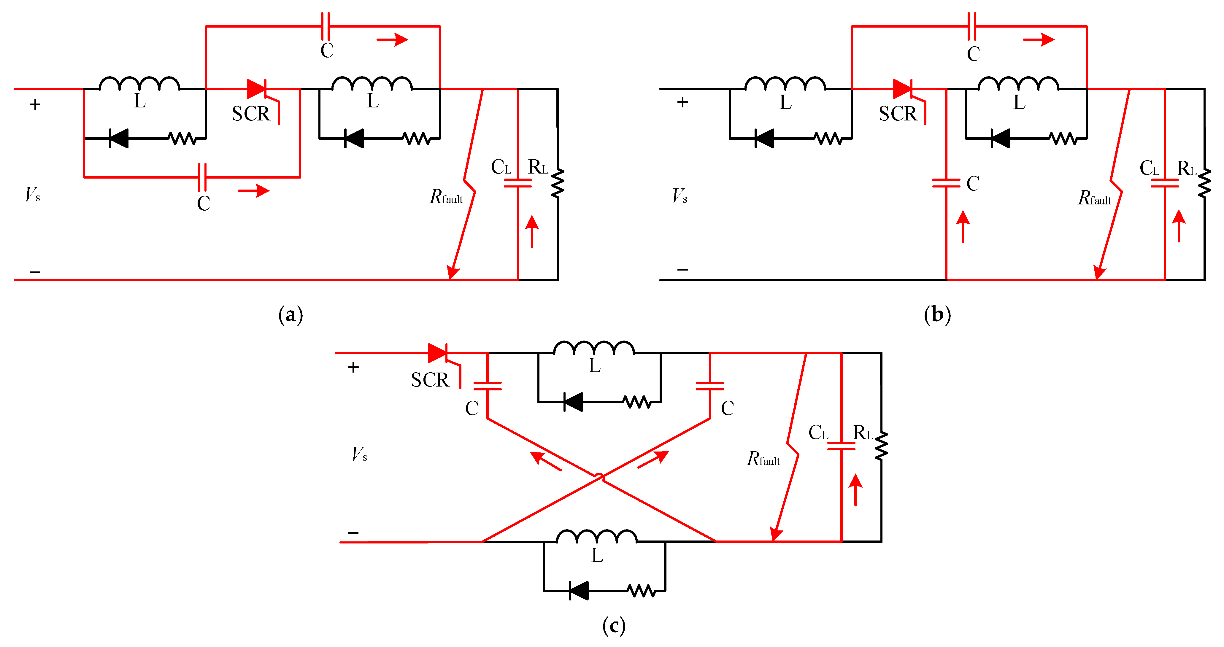
2. Overview of Z-Source Circuit Breakers
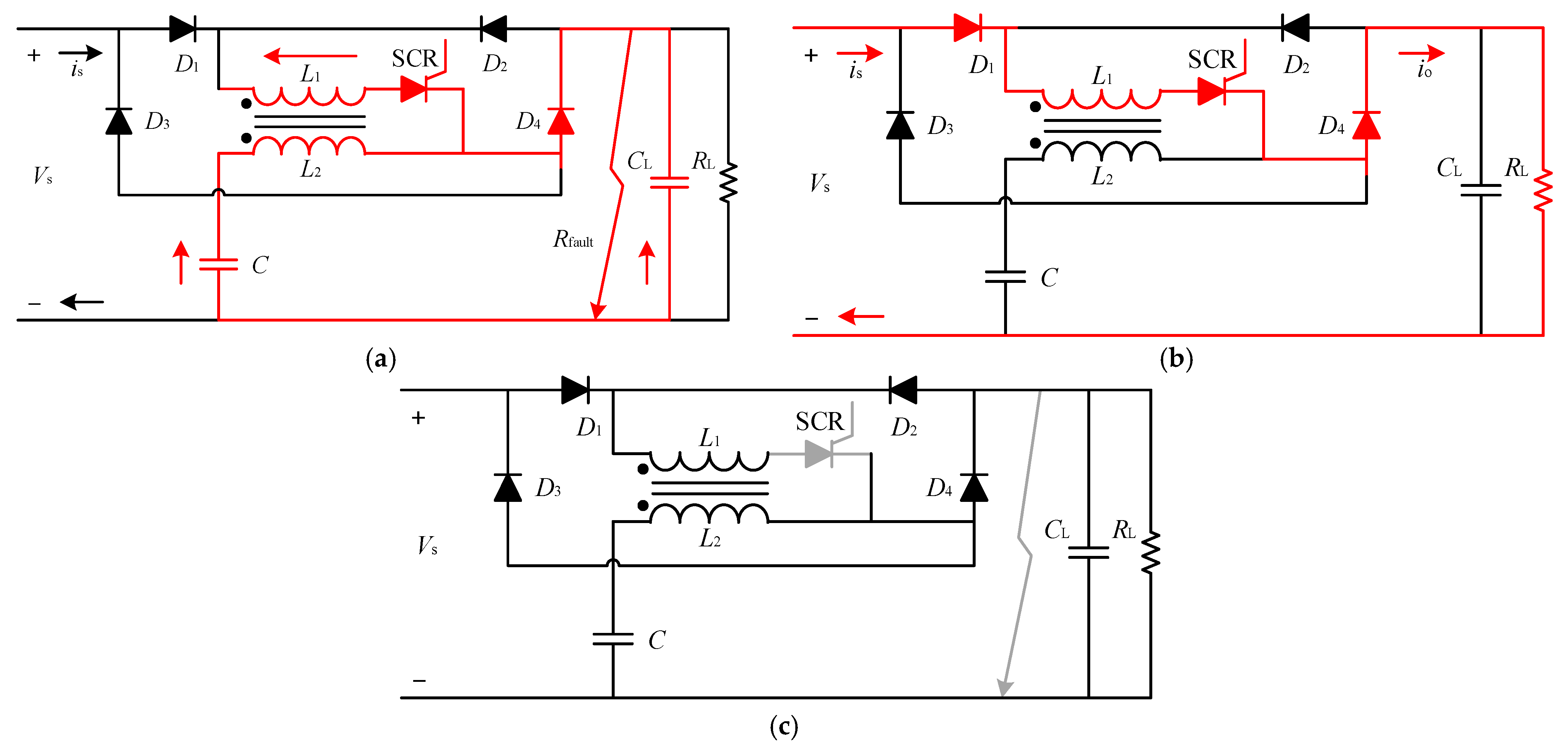
The DC microgrid has promoted the development of DC solid-state circuit breakers. The topology of traditional Z-source DC circuit breakers is divided into crossed topology, parallel-connected topology and series-connected topology.
Table 1 explains the type of circuit breaker represented by the symbol.
As shown in
Figure 1, the three types of DC circuit breakers are mainly composed of SCR, capacitor, inductance, and RD buffer circuits. The red line in
Figure 1 is the working state when the fault occurs. The fault current on the load side passes through the Z source capacitor and flows to the short-circuit point. Since the current in the line inductance cannot change suddenly when the reverse current in the SCR equals the steady-state load current of the line, the SCR is automatically closed, and the energy in the line decays to zero through the buffer circuit, thereby achieving the effect of quickly isolating the fault current.
Circuit structures, such as Γ-source and Z-source, are first applied to the research of inverters. With the development of PV Generation, they are applied to the field of solid-state DC circuit breakers. The crossed topology, shown in
Figure 1a, fails to provide a common ground point between the source and load, so the actual application of the project is affected. The parallel-connected topology is shown in
Figure 1b. The structure is transformed on the basis of the crossed type so that there is a common point between the source and the load, but when a fault occurs, the fault current will have a circulating current impact on the source side—
Figure 1c shows the series-connected topology. Along with the common point, the structural characteristics of the Z-source capacitor greatly reduce the impact of the fault current on the source side, so it has become a relatively ideal solution at present. As shown in
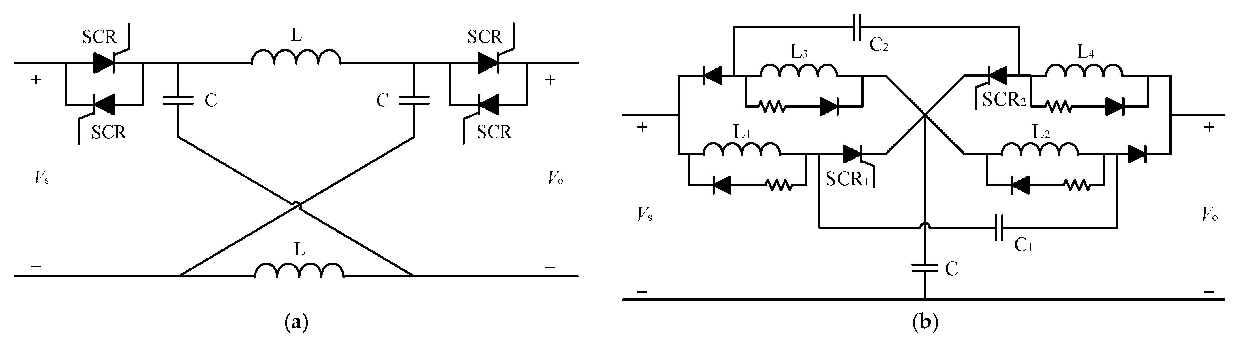
Figure 2, Three topology structures of bidirectional Z-source DC circuit are proposed by references [
13,
14].
Figure 2a,b shows that the characteristics of diode and SCR need to be used to achieve bidirectional operation, but the number of capacitors and inductances needs to be increased, and the current of LC branch will still have an impact on the source side. As shown in
Figure 2c, the bidirectional Z-source DC circuit breaker adopting coupled inductors uses the mutual inductance current in the coupled inductors to realize automatic shutdown of the SCR, but the two sets of coupled inductors increase the volume and cost.
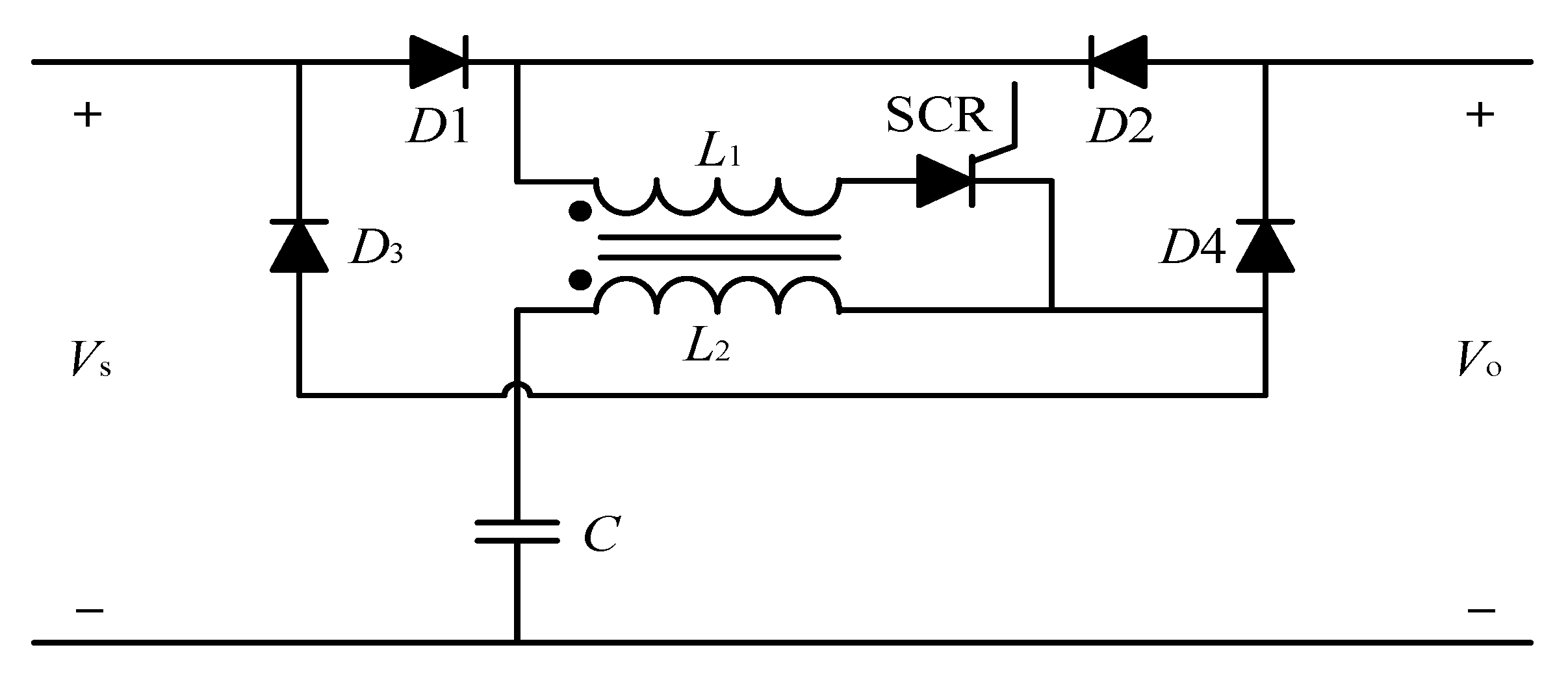
3. Design of Bidirectional DC Circuit Breaker Based on Flipped Γ-Source
The bidirectional DC circuit breaker based on flipped Γ-source is shown in
Figure 3, which is composed of a transformer, an SCR, capacitors, a diode bridge, a load capacitor and a load. Compared with the topology in
Figure 1, the topology in this paper uses the mutual inductance current produced by the transformer to force the SCR naturally commutate off, which replaces the LC branch of the traditional Z-source topology solves the problem of circulating current impact on the source side. The bidirectional dc circuit breaker proposed in this paper has full-bridge diodes. The full-bridge arrangement of diodes allows load current to flow in either direction while retaining the same conduction path through SCR. Thus, the bidirectional dc circuit breaker limits and interrupts fault current regardless of the direction of power flow. Owing to the diode bridge circuit in the topology, only one controlled switch can realize bidirectional operation protection. Compared with the topology in
Figure 2, only an SCR and a two-winding transformer are utilized to reduce the number RD buffer circuit. Thus, the topology is simplified while enabling it to have the capability of bidirectional operation protection.
To figure out the characteristics of different types of DC circuit breakers, the characteristics of various circuit breakers are analyzed in detail in
Table 2. The advantages of bi-based on flipped ΓSB proposed in this paper are discussed by comparing the common ground, bidirectional operation protection capability, fault current clearing capability, and the number of SCR. Compared with traditional ZSCBs, the ΓSCB using a transformer instead of two separate inductors can offer three advantages. The first advantage is a smaller volume, the second advantage is a settable turns ratio to optimize the protection, and the third advantage is the anti-saturation characteristic. The proposed topology can achieve bidirectional energy flow and achieve bidirectional fault interruption and isolation. Obviously, this topology has a simpler circuit, fewer components, and common ground compared with the previous approach.
3.1. Working Principle
Different operating states of ΓSCB are presented in
Figure 4. The forward energy flow channel consists of an SCR, the diode
D1 and
D2, capacitor
C, the primary coil
L1 of the transformer. Similarly, the SCR, the diode
D2 and
D3, capacitor
C, the primary coil
L1 of the transformer, constitute the channel of the reverse energy flow.
Figure 3.
A bidirectional DC Solid-state circuit breaker based on flipped Γ-source.
Figure 3.
A bidirectional DC Solid-state circuit breaker based on flipped Γ-source.
The normal operating states of the circuit are shown in
Figure 4a. At this time, the left side is the source, and the right side is the load. In the operating state, the conduction path from the source side to the load side through
L1 and SCR is shown in the red line of the Figure. The voltage across the capacitor
C can be regarded as equal to the supply voltage under the premise of neglecting the voltage drop of SCR. When the fault occurs on the load side, the working state of ΓSCB is shown in
Figure 4b. Part of the fault current generated by capacitor
C flows through the second coil of the transformer
L2 and
D4 to compensate for the fault current. The other part flows through load capacitor
CL to compensate for the fault current. During this process, the current in the secondary coil of the transformer
L2 will rise rapidly. Due to the mutual inductance of the transformer, the primary coil of the transformer
L1 will generate an induced current opposite to the original current
is, and when the two are equal, the SCR is turned off. After the SCR is turned off, the fault is completely isolated from the source side, and the current flows in the circulating path on the load side until the remaining energy decay to zero, as shown in
Figure 4c. Due to the diode bridge circuit, ΓSCB does not need to add a buffer circuit, and the working principle of the forward energy flow is equal to the reverse energy flow.
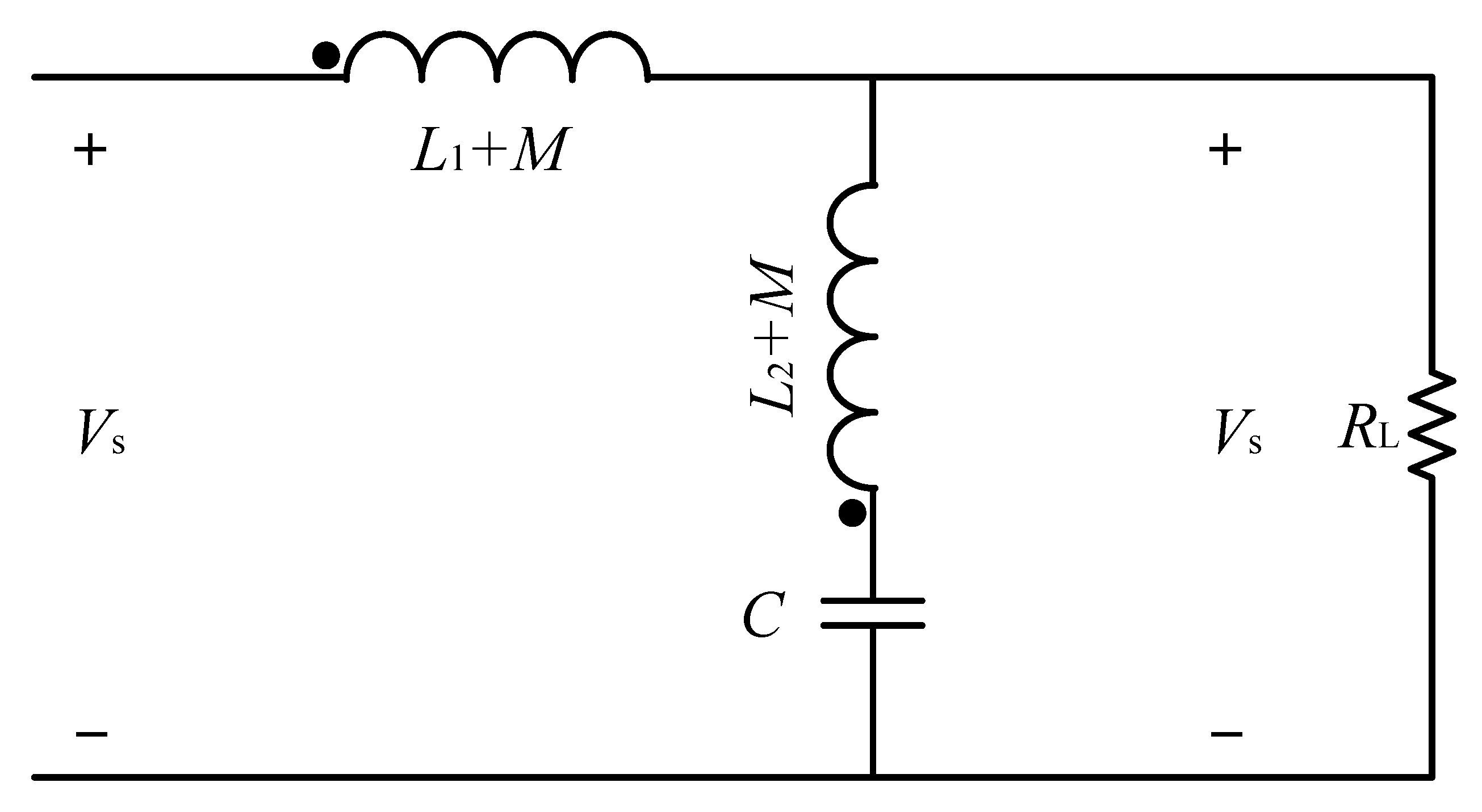
3.2. Analysis of the Impedance Network
k is the coupling coefficient of the two coupling coils, in this paper,
k = 1. When the DC circuit breaker is in normal working condition, the mutual inductance value of the two-winding transformer is
M.
The inductance of the primary and secondary coils of the transformer is L1 and L2.
According to the normal working equivalent circuit of DC circuit breakers in
Figure 5, the input and output voltage transfer function is determined, and the steady-state characteristics of the circuit are analyzed. In the case of a resistive load, through theoretical derivation, the output and input voltage transfer function can be obtained as:
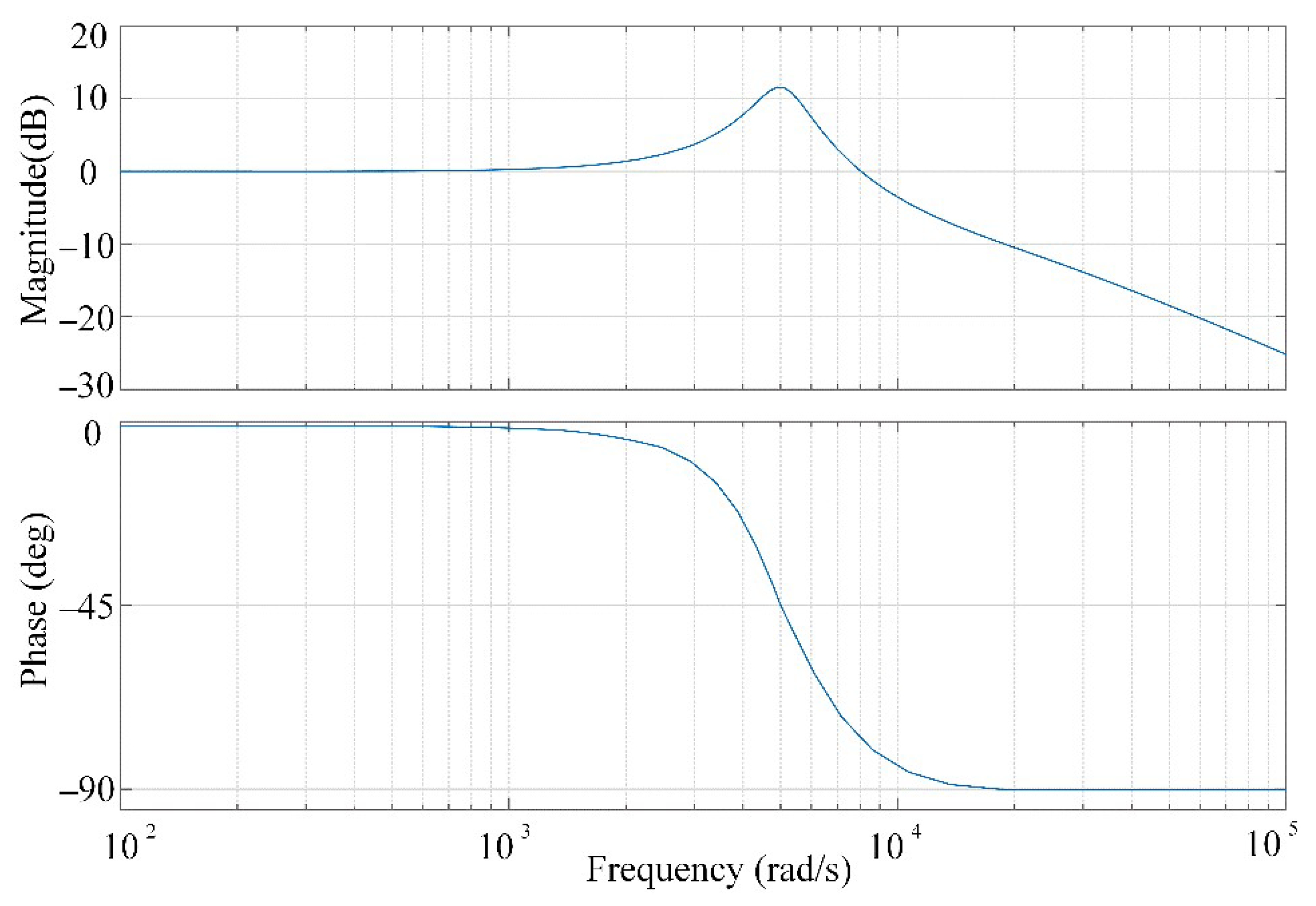
Substituting the relevant data of the simulation parameters into Formula (3), the specific Bode diagram can be obtained, as shown in
Figure 6, in the normal working state, the gain of the transfer function in the low-frequency range is approximately unity gain and the phase angle is close to zero degrees, which does not affect the normal operation of the system. In the high frequency range, it is very close to the function of the low-pass filter. Therefore, the topology structure plays a filtering role under the premise of protecting the system’s normal operation and guarantees the operating efficiency of the DC microgrid.
4. Analysis of Fault Current Change Rate
For the parameter design of the topological structure of the reversed ΓSCB, when a fault occurs on the load side, the SCR can force automatic commutation only when the fault current rises to a critical value to achieve the purpose of fault isolation, so the rate of rising of the fault current and the sum current are important parameters that determine the automatic shutdown of the SCR. According to
Figure 4b, the fault current
ifault, the secondary coil of the transformer
L2, capacitor
C and the load capacitor
CL form a loop. The current path of a short-circuit fault in the DC circuit breaker shows that the fault current
ifault can be expressed by the two capacitor line currents as:
In the initial state of short-circuit fault,
ifault can indicate:
In Formula (6),
Vo is the output voltage of the load,
G is the fault conductance. Neglecting the system line voltage drop, according to Formulas (4) and (6):
In Formula (7), Gmin expresses as the smallest detectable fault conductance.
The rate of rising of the short-circuit fault current determines the detection capability of the DC circuit breaker. The following analysis assumes that the change in fault conductance with time is a linear relationship, and the fault change rate
K can be expressed as:
where Δ
t is a time interval for the ramp. The fault current in terms of
K can be expressed as
According to Formula (5), we can receive
In the initial state when a fault occurs,
Vo =
Vs, from Formulas (4)–(6), we obtain
Vs is the source input voltage, from Formulas (9) and (11), the fault current
ifault and the current through Z-source capacitor are rewritten as
By solving Formula (13), the time at which capacitor current becomes maximum can be derived as
Substituting (14) into (13), maximum capacitor current can be obtained as
N is the turn of the winding
L1 and
L2 of the transformer, respectively. The ratio of the induced current between the primary coil and the secondary coil of the two-winding transformer is
iL1:
iL2 = 1:
N, and the induced current
iL2 on the secondary coil equals to capacitor current
ic, so when a fault occurs, the SCR can be automatically turned off when
,
is is the steady-state load current, so it can be obtained from Formula (15):
Therefore, when the change rate of the short-circuit fault conductance satisfies Formula (17), ΓSCB can work normally. Otherwise, the DC circuit breaker will not work normally. When determining the size of the system parameters, it needs to be based on the minimum fault current. It is required to select the appropriate CL/C ratio, set the minimum fault change rate by changing the size of the capacitor value, and also consider the short-term fault current level of the SCR and the reverse recovery time to ensure the normal operation of the DC circuit breaker
In order to achieve the appropriate minimum fault ramp rate
Kmin and to ensure the safe commutation of the SCR in sufficient time, the optimal value of the inductor must be selected, and the inductor current can be obtained:
According to Formulas (13) and (18), the current flow SCR can be obtained:
The inductor current should remain constant under fault conditions to minimize the detectable change rate of short-circuit faults. Therefore, the value of the inductance should be large enough so that the influence of the inductor current on the capacitor current is kept to a minimum. At the same time, the current through the SCR will not be affected.
In this paper,
N = 2, substituting (20) into (17), we obtain
Formula (21) shows the important relationship between the load RL and the system parameters, and the result also shows that the two-winding transformer is proportional to the capacitance C.
5. Extended the ΓSCB Simulation
In order to verify the effectiveness of the DC microgrid protection design based on the bidirectional DC circuit breaker based on flipped Γ-source in this paper. A simulation model with source voltage
UDC = 1 kV, the steady-state load current
is = 0.1 kA, and the short-circuit fault current peak value are 0.65 kA is established in the PSCAD/EMTDC software, and the working status of the DC circuit breaker when a short-circuit fault occurs on the load side is also analyzed. The two-way topology adopts two operating modes of the forward power flow and reverse power flow in the simulation. The mutual inductance value of the two-winding transformer is
M = 400 μH, and other relevant component parameters are shown in
Table 3.
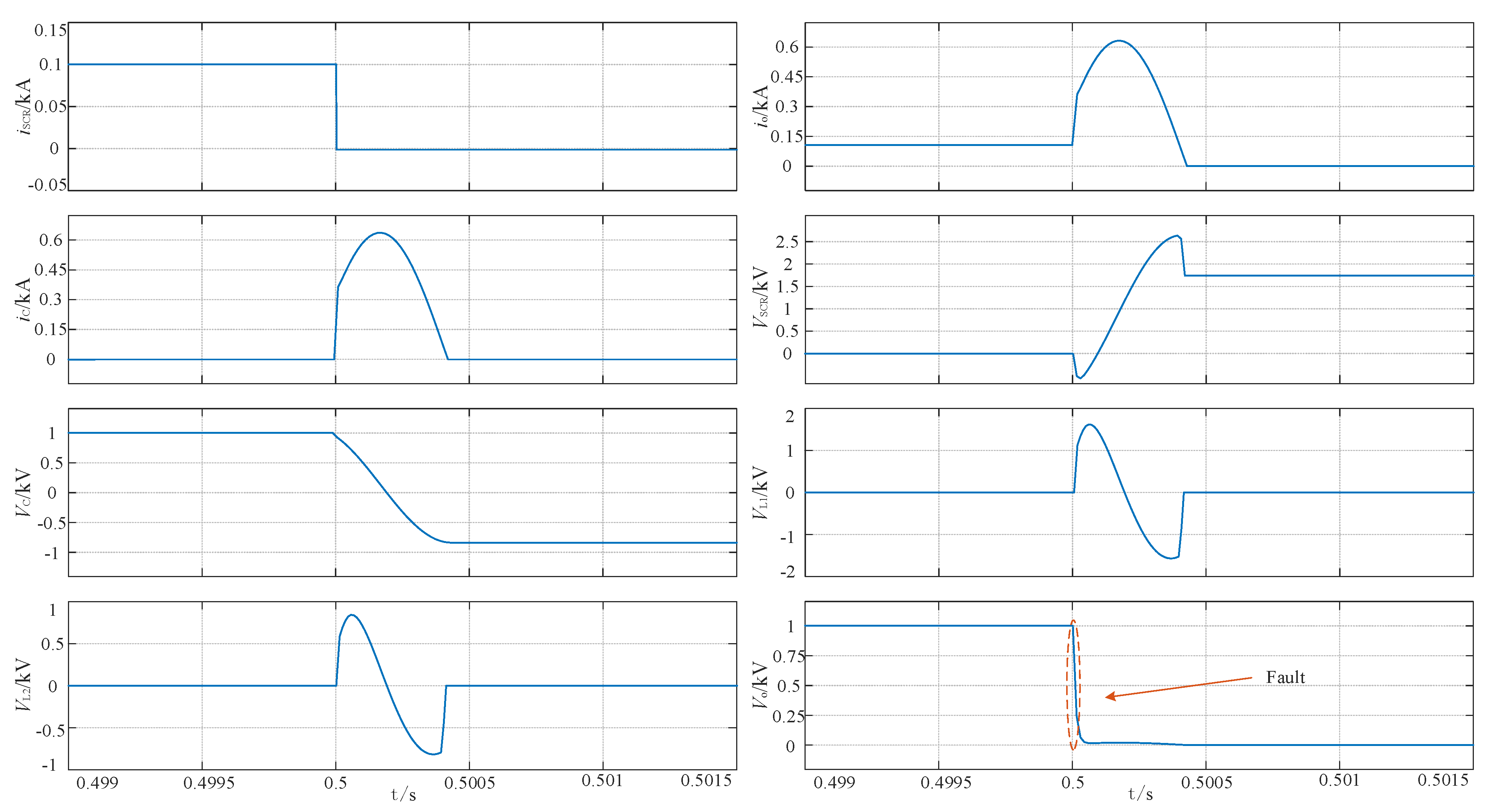
The simulation result of the topology of the ΓSCB is shown in
Figure 7. When the forward energy flow channel is running, the fault occurs on the load side when the simulation is set for 0.5 s, and the capacitor
C and the load capacitor
CL begin to discharge. The fault current rises rapidly, the magnetic flux of the secondary coil
L2 begins to increase, and the line current
iL2 rises.
Due to the mutual inductance between the transformer windings, the line current of the primary coil L1 continues to rise, forcing the SCR current to cross zero. Due to the symmetrical structure of the diode bridge circuit, there is no resonance effect, and the fault current is cleared after 400 μs. The voltage VSCR on both sides of the SCR is stabilized at 1.8 kV, the voltage Vc on both sides of the capacitor C is stabilized at 0.75 kV, the voltages VL1 and VL2 on both sides of the primary and secondary windings are reduced to zero after a period of sine, and the load-side output voltage Vo drops to zero. However, as the simulation time increases, the voltage on both sides of the SCR and capacitor C will slowly drop to zero after about 5.5 s.
As a result of the design of the diode bridge circuit, the ΓSCB is a symmetrical structure, so the simulation results under the reverse power flow operation of the bidirectional topology are consistent with the forward power flow operation. In the process of clearing the short-circuit fault current, it can be seen from the analysis of the simulation results that the bidirectional DC circuit breaker is designed to be suitable for the bidirectional operation of energy between different nodes and loads in the DC microgrid. Owing to the characteristics of the circuit structure, there is no need to add a buffer circuit and the ability to clear fault currents in a short time, which verifies the rationality of the topology of the ΓSCB.
The comparison simulation results of ΓSCB under different transformer parameters are shown in
Figure 8. The Figure shows the change of the short-circuit fault turn-off time and the fault current peak value of ΓSCB with the capacitor
C when the mutual inductance value is 400 μH and 600 μH. The circular line and the triangular line indicate the change under the condition of 400 μH, and the straight line and the diamond line indicate the change under the condition of 600 μH. Compared with the 600 μH conditions, the fault turn-off time under the 400 μH condition is short, and the fault current peak value is relatively high. With the continuous increase in the capacitor
C, the difference between the fault current peak value and the turn-off time under the two values also increases. When the capacitor
C is 200 μF, their gap is the smallest.
6. Experimental Validation
In order to verify the principle of the DC microgrid protection design based on the reversed Γ source bidirectional DC solid-state circuit breaker proposed in this paper, this section builds an experimental platform with a power supply voltage of 48 V, a steady-state load current of 1.2 A. The experimental platform verifies the load-side short-circuit fault detection and breaking process. A two-way experimental circuit is built for the diode bridge structure, and the experimental circuit schematic diagram of the ΓSCB turned over is shown in
Figure 9. In the diode bridge structure in
Figure 9,
L1 and SCR are long-term current-passing branches, RL simulates load resistance, Ro simulates load-side short-circuit fault resistance, short-circuit fault occurs after the air switch
Ksw is closed, capacitor
C starts to discharge, and the magnetic flux of
L2 rises until the SCR Automatic shutdown.
Because the voltage level of the experiment platform is relatively low, the current-limiting module does not need to be added. Because the circuit current rises rapidly after the Ro resistance is connected, the circuit breaker is turned off according to the expected effect. In selecting experimental devices, full consideration should be given to the withstand voltage level and rated current to avoid breakdown and damage of the experimental devices and ensure the experimenters’ personal safety. The physical diagram of ΓSCB turned over is shown in
Figure 10.
After the system works normally,
Ksw is closed, Ro is connected to the circuit to simulate a short-circuit fault, and the SCR reaches the critical value to force automatic commutation, and the entire experimental operation process ends. Part of the experimental waveforms of the ΓSCB is shown in
Figure 11. The experimental waveforms are SCR current waveform, output current waveform, SCR voltage waveform and output voltage waveform, and the time scale is 2 ms/div. It can be seen from the current and overvoltage waveform diagrams that under the condition of the source voltage of 48 V, the normal operating current of the entire DC system is 1.2 A, and the interruption fault current of the entire DC circuit breaker is about 400 μs. The circuit breaker topology designed in this paper reduces the number of SCR used and simplifies the overall structure on the basis of quickly shutting down the fault current. The experiment verifies the effectiveness of the topology of the flip Γ source DC circuit breaker.


