Article

Experimental Analysis of the R744/R404A Cascade Refrigeration System with Internal Heat Exchanger. Part 2: Exergy Characteristics

Department of Refrigeration and Air-Conditioning Engineering, College of Engineering, Chonnam National University, 50, Daehak-ro, Yeosu 59626, Korea
Energies 2022, 15(3), 1251; https://doi.org/10.3390/en15031251
Submission received: 10 January 2022 / Revised: 28 January 2022 / Accepted: 4 February 2022 / Published: 8 February 2022
(This article belongs to the Topic Exergy Analysis and Its Applications)

Abstract

:
This paper examines the exergy efficiency and exergy destruction rate of the R744/R404A cascade refrigeration system (CRS) using an internal heat exchanger in supermarkets according to various conditions affecting the system. A refrigerant of a low-temperature cycle uses R744 and a refrigerant of a high-temperature cycle in the CRS uses R404A. Experiments were conducted by changing various conditions on the high- and low-temperature side, and exergy analysis was performed accordingly. The main results are summarized as follows: (1) the lower the total exergy destruction rate of the CRS, the higher the exergy efficiency of the system, and accordingly the coefficient of performance (COP) of the system is also improved. (2) In the CRS, since the optimum cascade evaporation temperature exists (about −16 °C), it can be said that the limit point, that is, the cascade evaporation temperature with the maximum COP of the system, is the optimum point at about −16 °C. Therefore, at this optimum point, the exergy destruction rate of the cascade heat exchanger becomes the minimum. In other words, it should be noted that when the cascade evaporation temperature is the optimum point, the exergy destruction rate of the R744 compressor and the cascade heat exchanger is minimal. The purpose of this study is to provide basic design data by analyzing the exergy characteristics according to various conditions on the high- and low-temperature side for optimal design of a CRS to which R744 is applied.

1. Introduction

As shown in Table 1, R744 is eco-friendly and is safe because it is not toxic or flammable. Additionally, the price is low, the heat transfer rate is also larger than other refrigerants, and since the specific suction volume is small, it is possible to reduce the size of the refrigerator. In addition, since the latent heat of evaporation is large, the circulating flow rate is small, which has many advantages in terms of economy such as reducing the tube diameter. Due to these characteristics, energy can be saved by using R744 refrigerant in a low-temperature refrigeration system.
For this reason, R744 refrigerant is applied and widely used in the CRS used in large marts. In particular, R744 refrigerant has mainly been applied to the low-temperature side, and R290, R717, and R404A refrigerants have mainly been applied to the high-temperature side [1]. Additionally, in 1993, a study was conducted on the amount of refrigerant leakage in 220 large supermarkets in Norway, and it was reported that about 30% of the refrigerant leaked annually [2]. For this reason, R404A is safe as a refrigerant for large supermarket refrigerators used by many citizens despite the high GWP, so a CRS with R744 for the low-temperature side and R404A for the high-temperature side has been adopted and used widely [3]. In addition, research on the exergy of the CRS to which R744 is applied is being conducted.
Lee et al. [4] performed thermodynamic modeling using some assumptions and equilibrium equations (mass, energy, entropy, exergy) for the R744/R717 CRS, and the optimal condensing temperature of R744 cycle was determined to find the maximum coefficient of performance (COP) and minimize the system exergy destruction rate. Gholamian et al. [5] modeled and comprehensively evaluated the R717/R744 CRS and compared exergy destruction and COP with experimental data from the literature to verify the simulation code.
Aminyavari et al. [6] modeled and analyzed the R744/R717 CRS from an exergy, economic and environmental point of view. To obtain the optimal design parameters of the system, multi-purpose optimization using an algorithmic method was used, and the system’s exergy efficiency and total cost ratio (including maintenance cost, operating cost, and social cost of CO2 emission) were objectively considered.
Rangel and Almeida [7] were simulated using the Engineering Equation Solver software (EES) for R404A/R508b, propane/ethylene and propane/ethane CRS. Pan et al. [8] reviewed research on a CRS using HFC/HFO mixtures of refrigerants based on R134a, R404A and R410A refrigerants. Sun et al. [9] performed energy and exergy analysis in CRS using R23, R41 and R170 for the low-temperature side and R32, R1234yf, R1234ze, R161, R1270, R290 and R717 refrigerants for the high-temperature side.
Roy and Mandal [10] compared the energetic and exergetic performance for a numerical study of CRS using R170/R161 and R41/R404A working under the same operating conditions. Kumar [11] simulated the comparative analysis of CRS based on energy and exergy using different refrigerant pairs. Zhang et al. [12] experimentally investigated the performance of a R1270/CO2 CRS.
However, despite these many studies, the body of research on the exergy analysis of the R744/R404A CRS is insufficient, and moreover, studies on the R744/R404A CRS with an internal heat exchanger are even scarcer. Therefore, in this study, for the optimal design of the CRS to which R744 is applied, the exergy characteristics according to various conditions on the high and low-temperature side, such as the subcooling and superheating and internal heat exchanger efficiency that affect the exergy of the CRS, are considered to provide basic design data.
As can be seen from the above previous studies that cascade research is mostly based on simulation analysis rather than experiments, while R744 is applied to the low-temperature side and R717 is applied to the high-temperature side. In addition, research on mixtures refrigerants is in progress. However, research on the R744/R404A CRS applied in supermarkets used by many people is insufficient, and furthermore, it is difficult to find a cascade study using an internal heat exchanger. Lastly, most of the studies on CRSs use COP analysis. The study of the COP of R744/R404A CRS is used as basic data for design, but it is exergy that is effective in optimizing the performance of the system from the viewpoint of environment and energy. Therefore, exergy analysis is essential to optimize the system, to find the best system performance, and to reduce the exergy destruction rate of components. That is, in the R744/R404A CRS, by minimizing entropy generation and cycle irreversibility, I intend to perform exergy analysis to ultimately improve R744/R404A CRS efficiency. Therefore, the exergy characteristics according to a wide variety of conditions on the high and low temperature side, such as subcooling, superheating, and internal heat exchanger efficiency, are analyzed.

2. Experimental Apparatus and Data Reduction

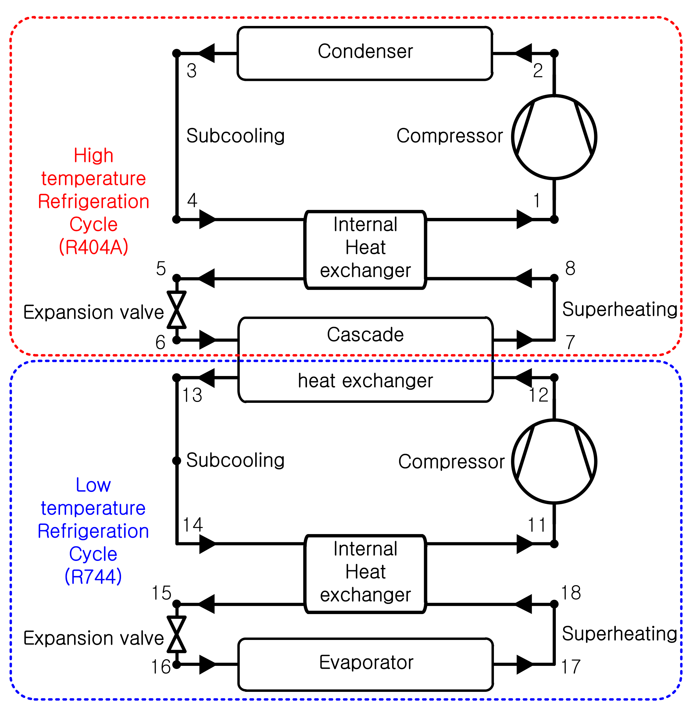
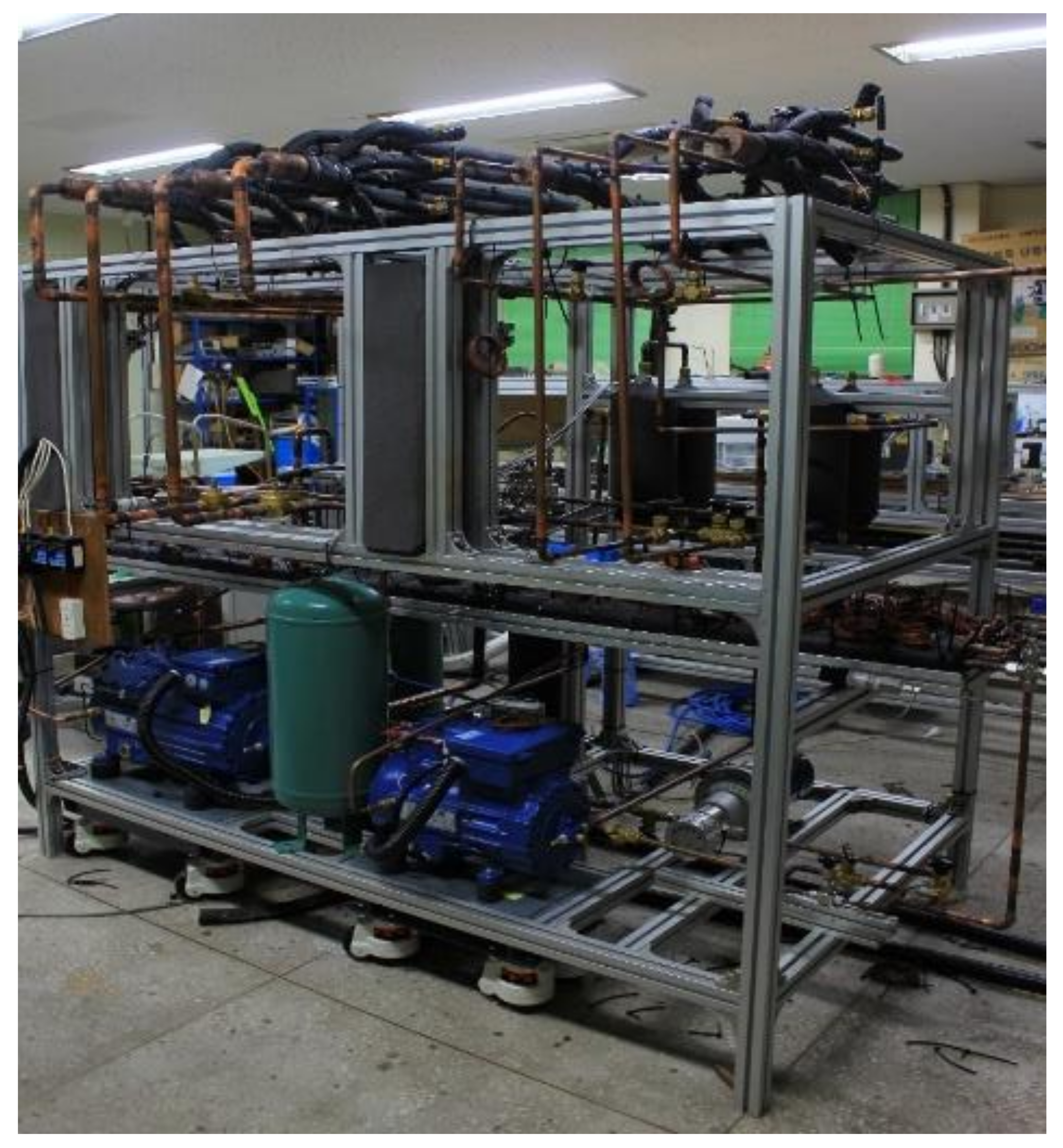
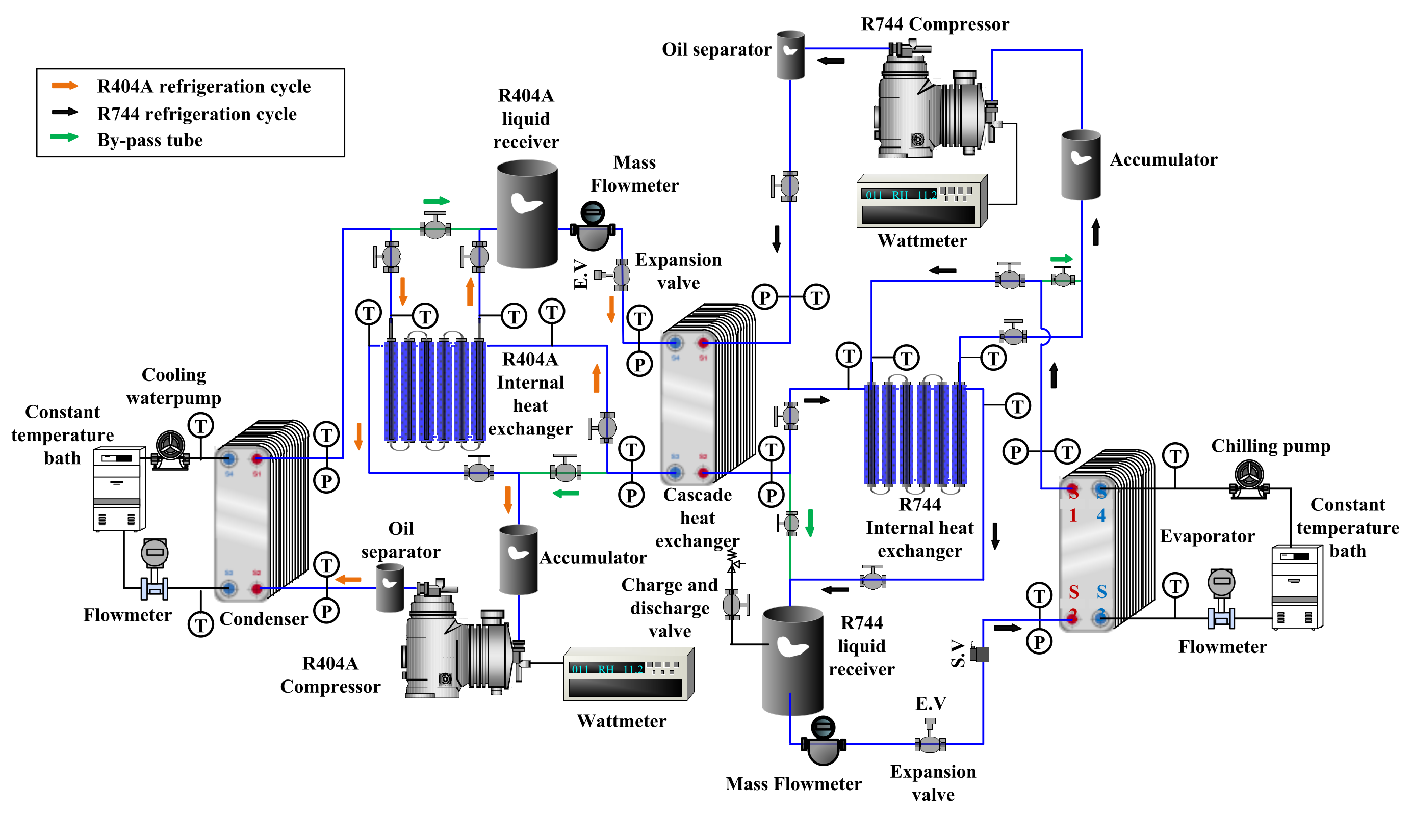
2.1. Experimental Apparatus

A photo of the actual experimental equipment of the cascade refrigeration system is shown in Figure 1, and the schematic diagram of the experimental equipment (Figure 2) was designed to understand the exergy characteristics of the R744/R404A CRS. For this purpose, the refrigerant temperature and pressure, mass flowrate, and power consumption of compressor at the inlet and outlet of the each component in the CRS were measured. The measurement position is shown in Figure 2.
Figure 2 was designed to analyze the characteristics of the R744/R404A CRS [13]. Additionally, the experimental procedure including the description of the experimental apparatus, the experimental conditions (Table 2), the main components and detailed characteristics of the experiments are the same as in a previous paper [13].
The main components of the experiments are listed in Table 3.

2.2. Data Reduction

The thermal properties of refrigerants used in this paper were calculated by REFPROP (version 8.01), a property program of the refrigerants that it was made by the National Institute of Standards and Technology (NIST) used. Using these thermal properties, the exergy characteristics of the R744/R404A CRS were investigated. For the experimental data analysis for this purpose, the following calculation formula were used.
In a system, the total exergy related to the kth material flow (fluid, such as refrigerant or work and heat) is the sum of chemical (CH), physical (PH), kinetic (KN) and positional (PT) exergy, as shown in the following formula [14,15].
E x ˙ k = E x ˙ k C H + E x ˙ k K N + E x ˙ k P T + E x ˙ k P H
where the subscript k means the kth component of the system.
Because chemical reactions do not occur within the components of the CRS to be analyzed in the future, and the kinetic exergy and positional exergy are negligible changes in the inlet and outlet of the system components, only the physical exergy ( E x ˙ k P H ) related to the kth material flow is considered [15,16].
E x ˙ k = E x ˙ k P H
Physical exergy can be obtained by the following formula under given temperature and pressure conditions [15,16].
E x ˙ k P H = m ˙ k i k i 0 T 0 s k s 0
The subscript 0 means the reference condition (ambient environment or atmosphere), T0 is the atmospheric temperature, P0 is the atmospheric pressure, and m ˙ k  is the material property value of the mass flow rate in the kth component.
The physical activity of all states in all components of the refrigeration system to be analyzed in the future can be separated into thermal ( E x ˙ k T ) and mechanical exergy ( E x ˙ k M ) (according to the approach presented in Morosuk [17]), as shown in Equation (4) below [18].
E x ˙ k = m ˙ k i k i k . P T 0 s k s k . P P = c o n s t E x ˙ k T + m ˙ k i k , P i 0 T 0 s k . P s 0 T = c o n s t E x ˙ k M
where i k , P and s k , P are specific enthalpy and entropy properties at the pressure and temperature given in the mass flow of the kth component of the system as Pk and Tk, respectively; the pressure is the isostatic pressure (Pk), and the temperature is the atmospheric temperature (T0). In addition, E x ˙ k T is the thermal exergy, and E x ˙ k M is the mechanical exergy. In other words, E x ˙ k T is the exergy due to temperature drop, E x ˙ k M is the exergy caused by the pressure drop.
The exergy equilibrium of the kth component of the system is as follows [19,20,21].
E x ˙ D , k = E x ˙ F , k E x ˙ P , k
A key element of exergy analysis is the general concept of E x ˙ F , k and E x ˙ P , k [19,20,21].
Exergy is the maximum theoretical useful work that can be obtained from an energy conversion system, and it interacts only with the thermodynamic environment and achieves a thermodynamic equilibrium with the thermodynamic environment [20,21].
The exergy efficiency of the system was calculated through Equation (6), as in Sun et al. [22].
η E x , S Y S = E x ˙ F , S Y S E x ˙ D , S Y S E x ˙ F , S Y S
To analyze the exergy of the system, the formula for calculating the exergy destruction rate ( E x ˙ D : exergy destruction rate, kW) for each component is summarized in Table 4 [15,22,23].
Variables such as evaporation temperature (TE) and condensing temperature (TC), cascade evaporation (TE,CAS) and condensation temperature (TC,CAS) of the cascade heat exchanger, degree of subcooling (∆TSUC,R404A, ∆TSUC,R744) and superheating (∆TSUH,R404A, ∆TSUH,R744), and internal heat exchanger efficiency (ηIHX,R404A, ηIHX,R744), which affect the COP, mass flow ratio and exergy of the R744/R404A CRS, were obtained using the calculated values from Table 4. The conceptual diagram of R744/R404A CRS is shown in Figure 3.

2.3. Uncertainties

In this study, the uncertainty of the COP and exergy destruction rates, etc., through experiments was predicted. The predictions were made through reference to the equations proposed by Kline and McClintock [24] and Moffat [25], and the predictions are summarized in Table 5.

3. Results and Discussion

This paper intends to provide basic design data by analyzing the exergy characteristics of the R744/R404A CRS. Therefore, the purpose of this study is to investigate the exergy destruction rate and system exergy efficiency according to the change in the degree of superheating and subcooling of the R404A cycle, condensation temperature, IHE efficiency of the R404A cycle, superheating degree of the R744 cycle, IHE efficiency of the R744 cycle, evaporation temperature, cascade evaporation temperature, etc.

3.1. Effect of the Degree of Subcooling and Superheating

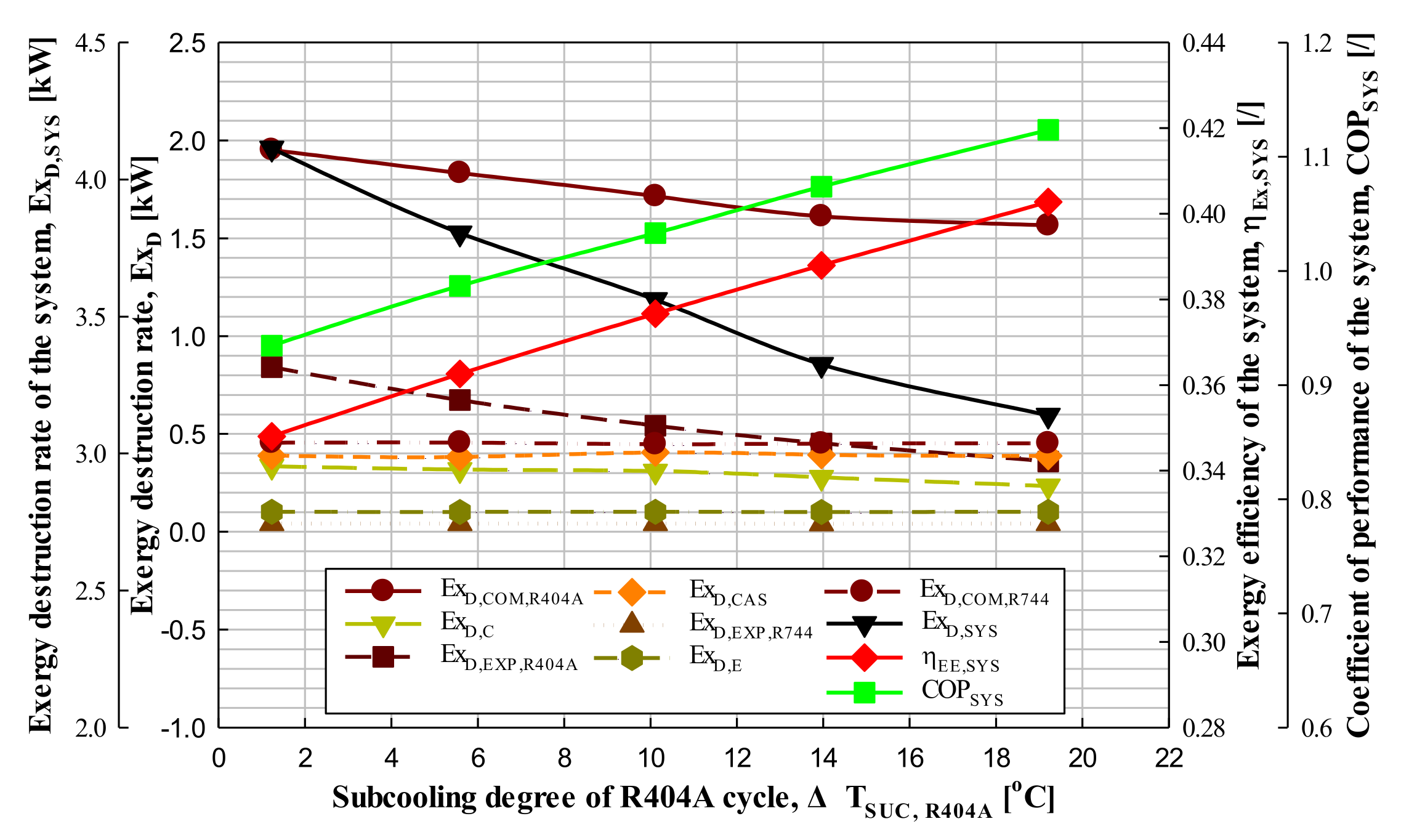
3.1.1. Effect of the Degree of Subcooling

An experiment was performed to find out how the exergy destruction rate and exergy efficiency of the system and each component device appeared as the degree of subcooling of the R404A cycle was increased in approximately 5 °C-intervals from 1.2 to 19.2 °C under the given conditions (QE = 5.83–5.91 kW, TE = −40.0–−39.8 °C, TE,CAS = −24.1–−23.9 °C, TC = 39.4–39.7 °C, ΔTCAS = 2.5–2.9 °C, ΔTSUH,R404A = 20.2–20.5 °C, ΔTSUH,R744 = 40.3–40.8 °C, ΔTSUC,R744 = 2.3–2.5 °C, ηIHX,R404A = ηIHX,R744 = 0).
As can be seen in Figure 4, as the degree of subcooling of the R404A cycle in the CRS increased by approximately 5 °C-intervals from 1.2 to 19.2 °C, the exergy destruction rate of the CRS decreased by 5.6–7.5%, and the exergy efficiency increased by 3–4.2%. Additionally, it was confirmed that the system exergy efficiency increases as the system COP increases. In this experiment, as the degree of subcooling of the R404A cycle was increased, the system exergy destruction rate decreased and the system exergy efficiency increased accordingly. Here, it was confirmed that the exergy efficiency and COP of the system showed the same trend as the degree of subcooling of the R404A cycle increased in the CRS.
Additionally, as can be seen in Figure 4, as the degree of subcooling of the R404A cycle in the CRS increased, the exergy destruction rate in the expansion valve, evaporator, compressor and cascade heat exchanger of the R744 cycle was almost unchanged according to the equation in Table 4, and the exergy destruction rates in the compressor, condenser and expansion valve of R404A cycle decreased by 2.8–6.4%, 2.5–16%, and 16.7–20.4%, respectively.
The reason for this result is that as the degree of subcooling of the R404A cycle increases, there is no change in the exergy destruction rate because the mass flow and all conditions do not change in the R744 cycle, so there is no change in the exergy destruction rate in the cascade heat exchanger. Additionally, it is judged that the exergy destruction rate in the compressor, condenser and expansion valve decreased as the mass flow rate of the R404A cycle decreased by 4.5–6%.
Therefore, it can be concluded that the exergy destruction rate of the system (ExD,SYS) decreases and the exergy efficiency of the system (ηEx,SYS) increases as the degree of subcooling increases in the R404A cycle. This was found to have the same results as seen in Yılmaz et al. [26].

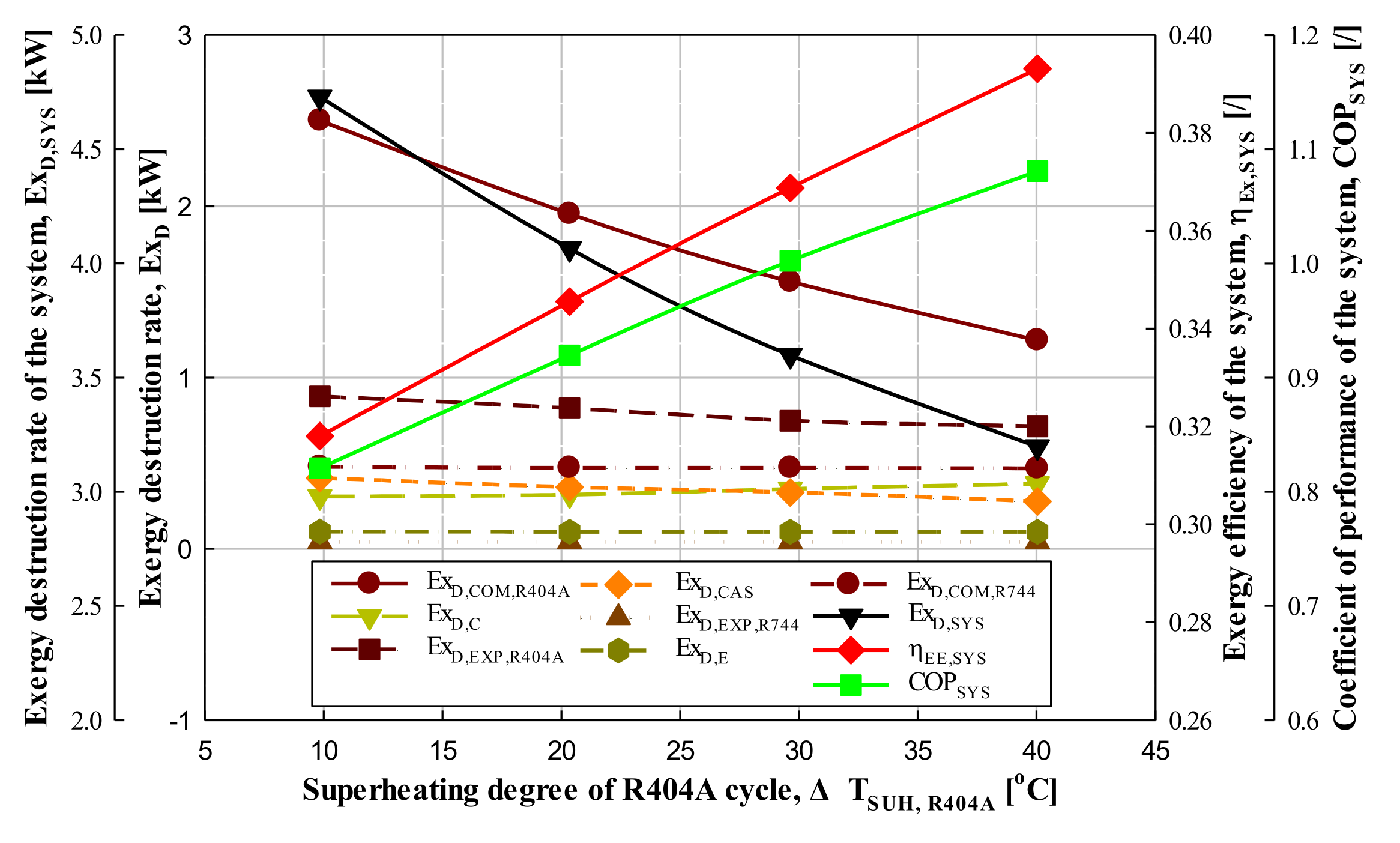
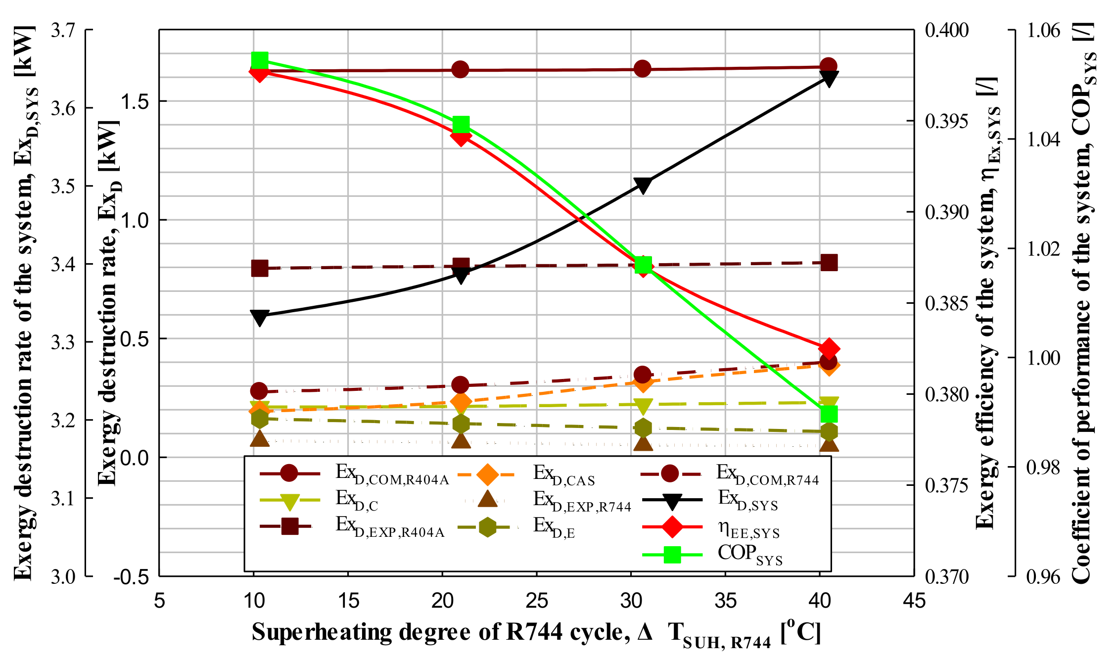
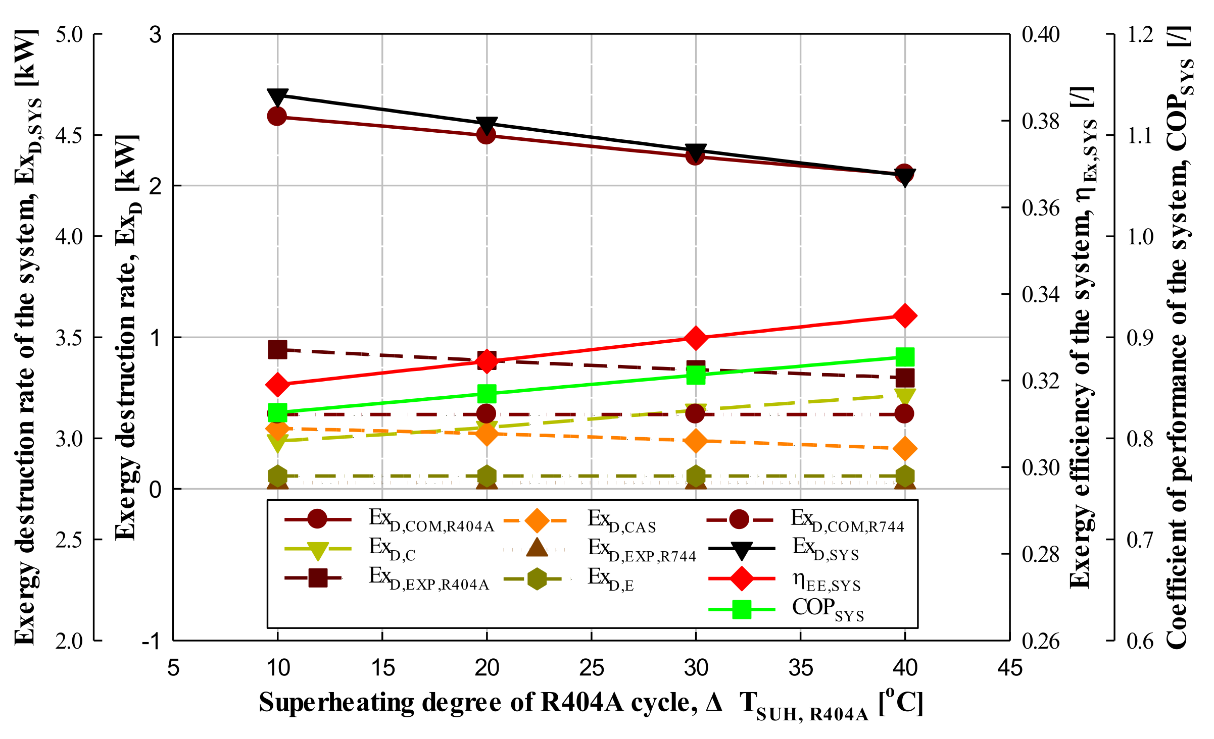
3.1.2. Effect of Degree of Superheating

An experiment was performed to find out how the exergy destruction rate and exergy efficiency of the system and each component were affected as the superheating degree of the R404A cycle increased by about 10 °C from 9.8 to 40 °C under the given conditions (QE = 5.69–5.71 kW, TE = -40.0–-39.8 °C, TE,CAS = -24.6–-24.3 °C, TC = 39.8–40.0 °C, ΔTCAS = 2.9–3.3 °C, ΔTSUH,R744 = 40.0–40.6 °C, ΔTSUC,R744 = 2.1–2.3 °C, ΔTSUC,R404A = 0.6–1.3 °C, ηIHX,R404A = ηIHX,R744 = 0).
As can be seen in Figure 5, as the superheating degree of the R404A cycle in the CRS increased in approximately 10 °C-intervals from 9.8 to 40 °C, the exergy destruction rate of the CRS decreased by 11.1–14%, and the exergy efficiency of the system increased by 6.6–8.7%. Additionally, it was confirmed that the exergy efficiency of the system increases as the COP of the system increases. In this experiment, as the superheating degree of the R404A cycle was increased, the exergy destruction of the system rate decreased, and the exergy efficiency of the system increased accordingly. Here, it was confirmed that the exergy efficiency and the COP of the system showed the same trend as the superheating degree of the R404A cycle increased in the CRS.
As shown in Figure 5, as the superheating degree of the high temperature cycle increased from 9.8 to 40 °C in the CRS, the exergy destruction rate in the expansion valve, evaporator and compressor of R744 cycle was almost unchanged, and the exergy destruction rate of the condenser in the R404A cycle increased by 3.5–10.6%, and the exergy destruction rate of the compressor, expansion valve and cascade heat exchanger in the R404A cycle decreased by 20.2–22%, 4.3–9.1%, and 8.6–15.9%, respectively.
The reason for this result is that as the superheating degree of the high temperature cycle increases, there is no change in the exergy destruction rate because the mass flow rate and all conditions do not change in the R744 cycle, and the exergy destruction rate of the compressor, expansion valve and cascade heat exchanger decreases as the mass flow rate decreases by 6.3–7.7% in the R404A cycle. However, the exergy destruction rate (ExD,C) in the condenser alone increases by 3.5–10.6%. Here, the exergy destruction rate in the condenser is calculated as the sum of the exergy destruction rate of the inlet and outlet refrigerant (ExF,C: +) and the exergy destruction rate due to the heat of condensation (ExP,C: −). Additionally, as the mass flow rate of the refrigerant decreases, both the exergy destruction rate of the refrigerant and the exergy destruction rate due to the heat of condensation decrease, but since the decrease in the exergy destruction rate due to the condensation heat is larger than the decrease in the exergy destruction rate of the inlet/outlet refrigerant, the total exergy destruction rate in the condenser is increased.
Therefore, it can be concluded that the exergy destruction rate of the system (ExD,SYS) decreases and the exergy efficiency of the system (ηEx,SYS) increases as the superheating degree increases in the R404A cycle. This was found to have the same results as seen in Yilmaz et al. [26].
An experiment was conducted to find out how the exergy destruction rate and exergy efficiency of the system and each component device appeared as the superheating degree of the R744 cycle was increased in approximately 10 °C-intervals from 10.3 to 40.5 °C under the given conditions (QE = 5.83–5.84 kW, TE = −40.1–−39.8 °C, TE,CAS = −21–−20.6 °C, TC = 42.0–42.4 °C, ΔTCAS = 2.8–3.0 °C, ΔTSUC,R744 = 1.8–2.4 °C, ΔTSUH,R404A = 15.4–15.7 °C, ΔTSUC,R404A = 1.4–1.7 °C, ηIHX,R404A = ηIHX,R744 = 0).
As can be seen in Figure 6, as the superheating degree of the R744 cycle in the CRS increased in approximately 10 °C-intervals from 10.3 °C to 40.5 °C, the exergy destruction rate of the CRS increased by 1.7–4.9%, and the exergy efficiency of the system was decreased by 0.03–2.3%. Additionally, it was confirmed that the exergy efficiency of the system decreased as the COP of the system decreased. In this experiment, as the superheating degree of the R744 cycle increased, the exergy destruction rate of the system increased, and the exergy efficiency of the system decreased accordingly. Here, it was confirmed that the exergy efficiency and the COP of the system showed the same trend as the superheating degree of the R744 cycle increased in the CRS.
As can be seen in Figure 6, as the superheating degree of the R744 cycle increased from 10.3 to 40.5 °C in the CRS, the exergy destruction rates of the expansion valve and the evaporator in the R744 cycle (ExD,EXP,R744, ExD,E) decreased by 3.7–5.9% and 10.7–23%, respectively, while the exergy destruction rate of the compressor, condenser, expansion valve and cascade heat exchanger in the R404A cycle (ExD,COM,R404A, ExD,C, ExD,EXP,R404A, ExD,CAS) increased by 0.06–0.08%, 1–1.6%, 0.3–8%, and 21.8–34.9%, respectively, and the exergy destruction rate of the compressor in the R744 cycle (ExD,COM,R744) increased by 9.4–16.6%. The reason for this result is that as the superheating degree of the R744 cycle increases, the mass flow rate decreases by 2.7–3.7% in the R744 cycle, and the exergy destruction rates of the expansion valve and the evaporator (ExD,EXP,R744, ExD,E) decrease. In spite of the decrease in the mass flow rate of the R744 cycle, the exergy destruction rate of the compressor in the R744 cycle (ExD,COM,R744) increased as the power consumption of the compressor in the R744 cycle increased. In addition, the exergy destruction rate of the cascade heat exchanger (ExD,CAS) increased significantly to 21.8–34.9% due to the increase in the heat of condensation in the R744 cycle and the mass flow in R404A due to the increase in the power consumption of the compressor in the R744 cycle, and the exergy destruction rates of the compressor, condenser, expansion valve in the R404A cycle (ExD,COM,R404A, ExD,C, ExD,EXP,R404A) are also considered to increase.
Therefore, it can be concluded that the exergy destruction rate of the system (ExD,SYS) increases and the exergy efficiency of the system (ηEx,SYS) decreases as the superheating degree increases in the R744 cycle. This was found to have the same results as seen in Mosaffa et al. [27].

3.2. Effect of Condensation and Evaporation Temperature

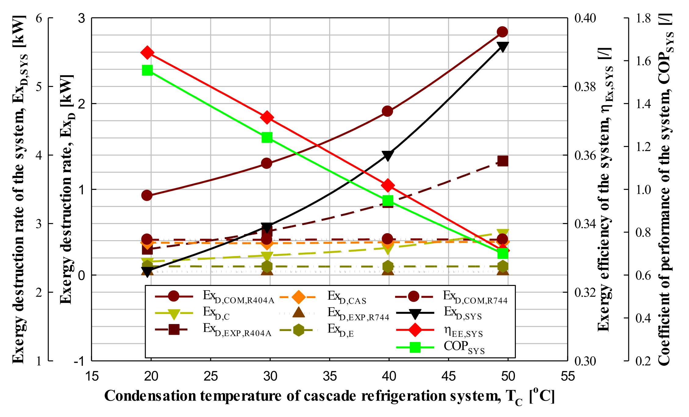
3.2.1. Effect of Condensation Temperature

An experiment was performed to find out how the exergy destruction rate and exergy efficiency of the system and each component were affected as the condensation temperature of the CRS was increased in approximately 10 °C-intervals from 19.7 to 49.6 °C under the given conditions (QE = 5.84–5.90 kW, TE = −40.1–−39.7 °C, TE,CAS = −25.0–−24.4 °C, ΔTCAS = 2.9–3.2 °C, ΔTSUH,R404A = 20.5–21.4 °C, ΔTSUC,R404A = 1.0–1.6 °C, ΔTSUH,R744 = 40.2–40.7 °C, ΔTSUC,R744 = 1.9–2.5 °C, ηIHX,R404A = ηIHX,R744 = 0).
As can be seen in Figure 7, as the condensation temperature in the CRS increased in approximately 10 °C-intervals from 19.7 °C to 49.6 °C, the exergy destruction rate of the system increased by 28–39.6%, and the exergy efficiency of the system was decreased by 4.9–5.4%. Additionally, it was confirmed that the exergy efficiency and COP of the system showed the same trend as the condensation temperature increased in the CRS. In addition, as the condensation temperature of the CRS is increased in approximately 10 °C-intervals from 19.7 °C to 49.6 °C, there is little change in the exergy destruction rate of the expansion valve, evaporator, compressor and cascade heat exchanger in the R744 cycle, and the compressor, condensers and expansion valve in the R404A cycle (ExD,COM,R404A, ExD,C, ExD,EXP,R404A) all increased by 40.6–48.6%, 39.2–55.3%, and 57.3–69.1%, respectively.
The reason for this result is that as the condensation temperature of the CRS increases, the specific enthalpy and entropy values at the outlet of the compressor in the R404A cycle increase, and the specific enthalpy and entropy values at the outlet of condenser also increase, but the specific enthalpy and entropy values at the inlet increase significantly. The power consumption of R404A compressor and condensation capacity increased. Additionally, as the condensation temperature of the system increases, the mass flow rate of the R404A cycle increases and the exergy destruction rate of the compressor, condenser, and expansion valves in the R404A cycle (ExD,COM,R404A, ExD,C, ExD,EXP,R404A) increases. In the R744 cycle, the operating conditions and mass flow rate did not change, so the exergy destruction rate hardly increased or decreased.
Here, the increase in the exergy destruction rate of the R404A cycle components is high overall, and among them, the increase in the exergy destruction rate at the expansion valve was the largest as 58.4–65.9%. Of course, it is also the result of an increase in mass flow, but in detail, the exergy destruction rate according to the pressure drop (ExD,EXP,R404AM, ExF,EXP,R404A: +) greatly increased, whereas the exergy destruction rate according to the temperature drop (ExD,EXP,R404AT, ExP,EXP,R404A: −) decreased. Therefore, it is judged that the amount of exergy destruction of the expansion valve is further increased.
Therefore, it can be concluded that as the condensation temperature increases in the CRS, the exergy destruction rate of the system (ExD,SYS) increases and the exergy efficiency of the system decreases. This was found to have the same results as Yilmaz et al. [26], Hendri et al. [28], Parekh and Tailor [29], and Kilicarslan and Hosoz [30].

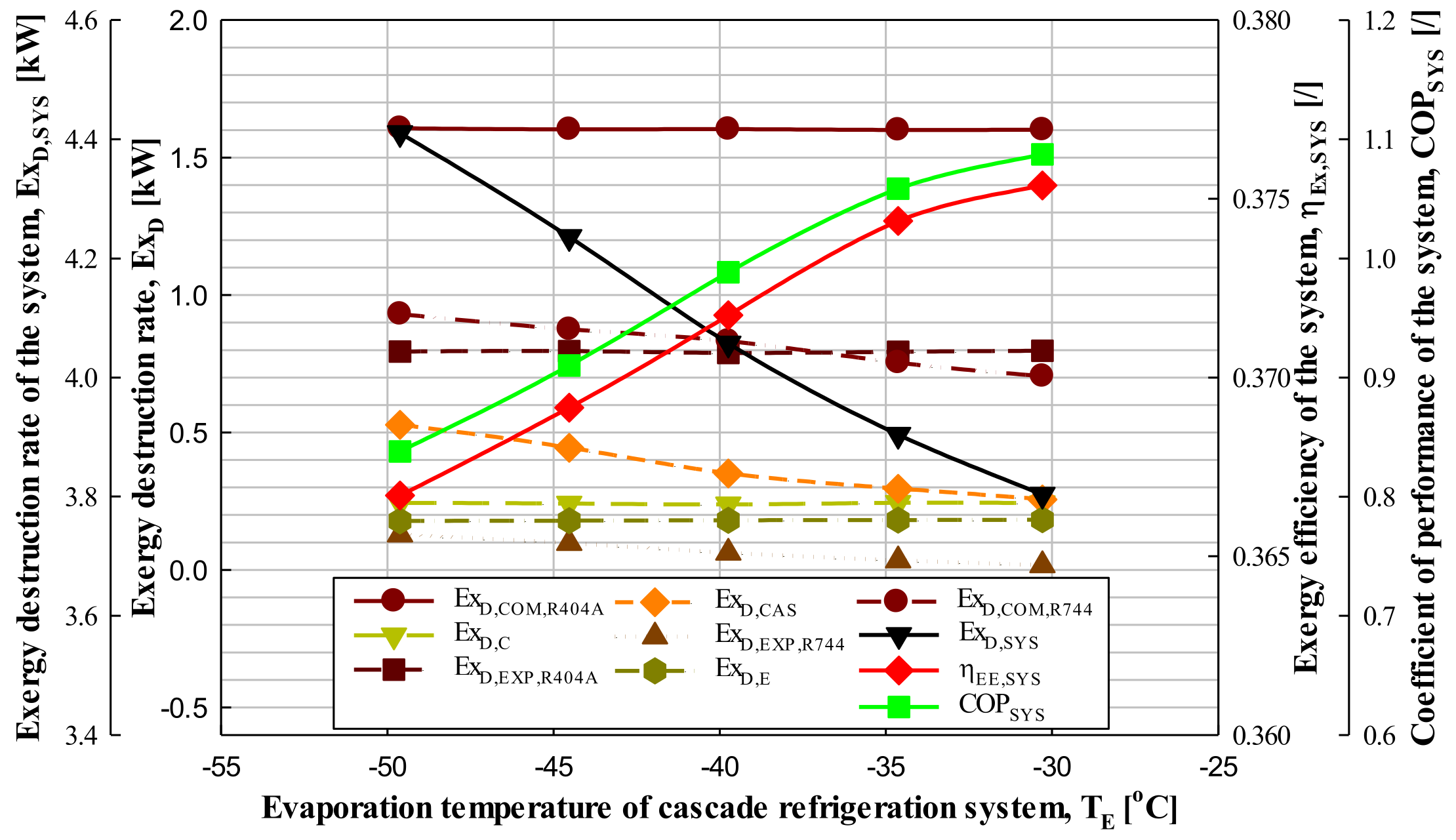
3.2.2. Effect of Evaporation Temperature

Experiments were performed to find out how the exergy destruction rate and exergy efficiency of the CRS and each component device appeared as the evaporation temperature of the system was increased by approximately 5 °C-intervals from −49.6 °C to −30.3 °C under the given conditions (QE = 4.65–5.96 kW, TE = −40.1–−39.7 °C, TC = 41.0–41.6 °C, ΔTCAS = 2.9–3.4 °C, ΔTSUH,R744 = 10.4–10.8 °C, ΔTSUC,R744 = 1.0–1.5 °C, ΔTSUH,R404A = 20.2–20.8 °C, ΔTSUC,R404A = 1.4–1.9 °C, ηIHX,R404A = ηIHX,R744 = 0).
As can be seen from Figure 8, as the evaporation temperature of the CRS increased by approximately 5 °C-intervals from −49.6 to −30.3 °C, the exergy destruction rate of the system decreased by 2.6–4.2%, and the exergy efficiency of the system increased by 0.3–0.7%. Additionally, it was confirmed that the exergy efficiency and COP of the system increased as the exergy destruction rate of the system decreased as the evaporation temperature increased. In addition, in the CRS, as the evaporation temperature increased from −49.6 to −30.3 °C in approximately 5 °C-intervals, the exergy destruction rate of the expansion valve, compressor, and cascade heat exchanger in the R744 cycle (ExD,EXP,R744, ExD,COM,R744, ExD,CAS) decreased by 24.4–50.6%, 4.9–9.4%, and 15.8–21.1%, respectively, while the exergy destruction rate of the evaporator in the R744 cycle (ExD,E) increased by 0.4–0.7%. Additionally, there was almost no change in the exergy destruction rates of the compressor, condenser, and expansion valve in the R404A cycle (ExD,COM,R404A, ExD,C, ExD,EXP,R404A).
The reason for this result is that as the evaporation temperature of the CRS increases, the specific enthalpy and entropy difference and mass flow rate of each device in the R404A cycle do not change, so the exergy destruction rate hardly changes, and as the evaporation temperature increases, the evaporator inlet specific enthalpy of the R744 cycle (i16) is constant and the evaporator outlet specific enthalpy of the R744 cycle (i18) increases, so the specific enthalpy difference (i18-i16) of the evaporator inlet and outlet increases. The specific entropy of both the evaporator inlet and outlet (s16, s18) decreases, but the specific entropy of the outlet (s18) is greatly reduced compared to the inlet specific entropy (s16), so the specific entropy difference (s18-s16) between the inlet and outlet of the evaporator decreases and the mass flow rate increases. Additionally, although both the exergy destruction rate of refrigerant and the exergy destruction rate due to the evaporation capacity decrease, the amount of decrease in the exergy destruction rate caused by the heat of evaporation is greater than that of the refrigerant, so it is judged that the exergy destruction rate of the evaporator increases.
Additionally, as the evaporating temperature of the R744 cycle increases, the specific entropy difference of the inlet and the outlet in the expansion valve (s16-s15) decreases. It is judged that the exergy destruction rate of the expansion valve decreases because the exergy destruction rate according to the pressure drop is greater than the exergy destruction rate according to the temperature drop.
In addition, in the R744 cycle, both the specific entropy difference (s12-s11) and the specific enthalpy difference (i12-i11) of the compressor inlet and outlet decrease in the exergy destruction rate of the R744 compressor, but the specific entropy difference decreases significantly compared to the specific enthalpy difference, so the exergy destruction rate of the compressor decreases. Finally, when checking the exergy destruction rate of the cascade heat exchanger, there is no change in the exergy because the specific entropy difference (s8-s6) and the mass flow rate of the cascade evaporator inlet and outlet in the R404A cycle do not change. On the other hand, the specific entropy difference (s12-s14) of the inlet and outlet of the cascade condenser in the R744 cycle decreases and the mass flow rate increases. This is why it is judged that the exergy destruction rate of the cascade heat exchanger is reduced.
Therefore, it can be concluded that the exergy destruction rate of the CRS decreases and the exergy efficiency of the system increases as the evaporation temperature increases in the system. This was confirmed to be consistent with the results of the papers of Mosaffa et al. [27], Yilmaz and Selbaş [31], Dokandari et al. [32], and Dopazo et al. [33].

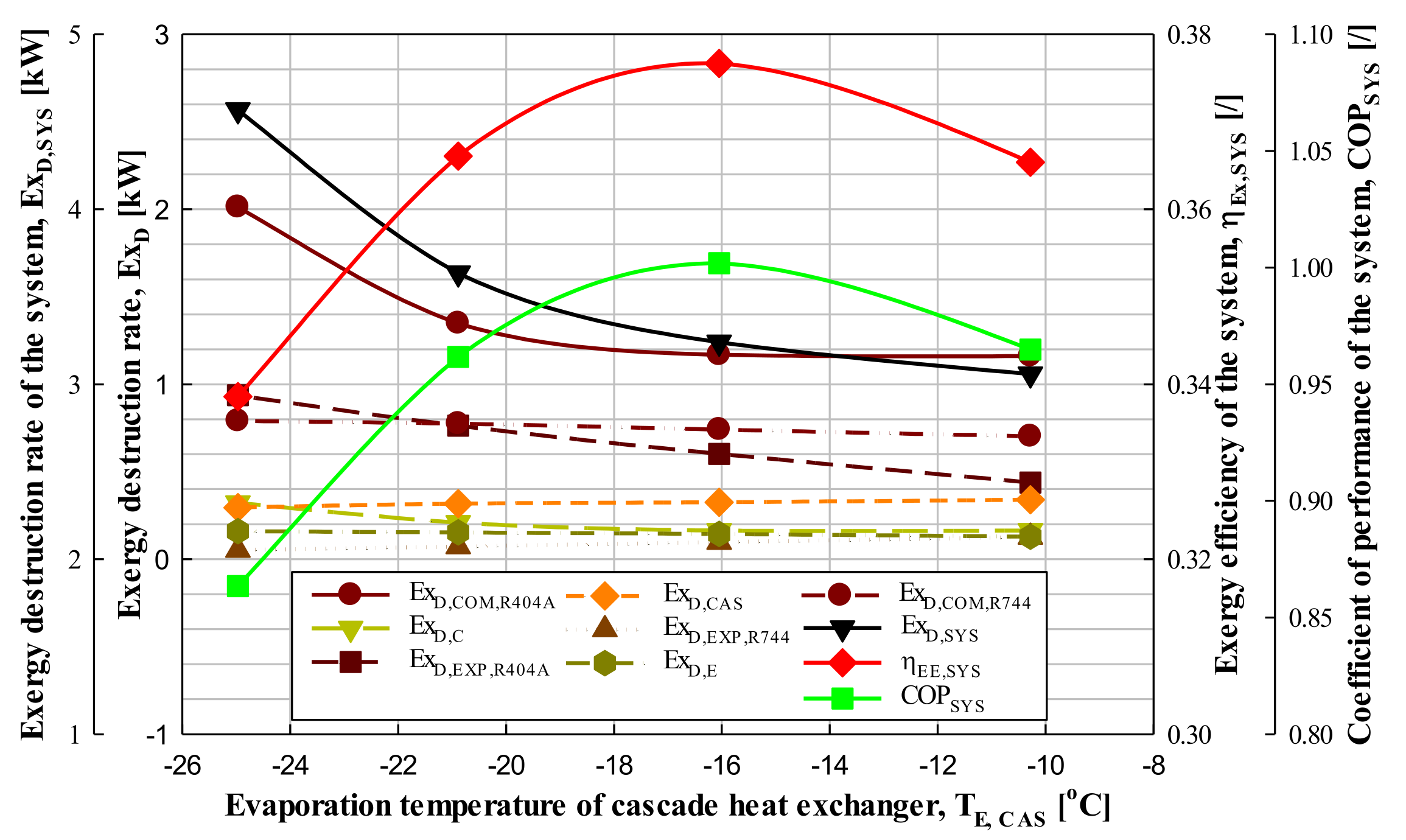
3.3. Effect of Evaporation Temperature of Cascade Heat Exchanger

An experiment was performed to find out how the exergy destruction rate and exergy efficiency of the CRS and each component device were affected as the evaporation temperature of the cascade heat exchanger increased in approximately 5 °C-intervals from −25.0 to −10.3 °C under the given conditions (QE = 4.65–5.96 kW, TE = −40.1–−39.7 °C, TC = 41.0–41.6 °C, ΔTCAS = 2.9–3.4 °C, ΔTSUH,R744 = 10.4–10.8 °C, ΔTSUC,R744 = 1.0–1.5 °C, ΔTSUH,R404A = 20.2–20.8 °C, ΔTSUC,R404A = 1.4–1.9 °C, ηIHX,R404A = ηIHX,R744 = 0).
As can be seen in Figure 9, as the cascade evaporation temperature in the CRS increased in approximately 5 °C-intervals from −25.0 °C to −10.3 °C, the exergy destruction rate of the system decreased by 5.9–25.6%, and the exergy efficiency of the system increased and then decreased by 2.8–7.5%. More specifically, as the cascade evaporation temperature increased, the exergy efficiency of the system increased from the cascade evaporation temperature of −25.0 to −16.0 °C, reached the highest efficiency of 37.7% at −16.0 °C, and decreased from −16.0 °C to −10.3 °C. It was confirmed that the change was the same as the increase/decrease trend of COP.
Additionally, as shown in Figure 9, as the cascade evaporation temperature increased from −25.0 to −10.3 °C in the CRS at approximately 5 °C-intervals, the exergy destruction rate of the expansion valve and cascade heat exchanger in the R744 cycle (ExD,EXP,R744, ExD,CAS) increased by 23–27.7% and 2.7–6.9%, respectively, and the exergy destruction rate in the evaporator and compressor in the R744 cycle (ExD,E, ExD,COM,R744) and the compressor, condenser and expansion valve in the R404A cycle (ExD,COM,R404A, ExD,C, ExD,EXP,R404A) decreased by 4.7–11.6%, 2.0–5.5%, 0.7–49.2%, 0.1–53.9%, and 22.9–37.3%, respectively.
The reason for this result is that as the cascade evaporation temperature increases, the exergy destruction rate of the evaporator and compressor in the R744 cycle and the compressor, condenser, and expansion valve in the R404A cycle decrease due to the decrease in mass flow rate. Additionally, as the cascade evaporation temperature increased, the exergy destruction rate of the expansion valve in the R744 cycle (ExD,EXP,R744) increased. This means that both the exergy destruction rate according to the temperature and pressure drop increase, but the increase rate of the exergy destruction rate according to the temperature drop ( E x D , E X P , R 744 T , ExP,EXP,R744: −) is smaller than the rate of increase in the exergy destruction rate according to the pressure drop ( E x D , E X P , R 744 M , ExF,EXP,R744: +), so the exergy destruction rates of the expansion valve (ExD,EXP,R744) are judged to increase. That is, this means that the effect of the increase rate of the exergy destruction rates (ExP,EXP,R744) according to the temperature drop has a greater effect than the effect of the decrease in the mass flow rate of the R744 cycle.
Additionally, in the cascade heat exchanger, as the cascade evaporation temperature increases, the exergy destruction rate of the cascade evaporator (ExF,CAS: +) and the exergy destruction rate of the cascade condenser (ExP,CAS: −) both decrease, but the reduction ratio of ExP,CAS is greater than that of ExF,CAS, so it is judged that the exergy destruction rate of the cascade heat exchanger increases.
Therefore, it can be concluded that as the cascade evaporation temperature increases in a CRS, the exergy destruction rate of the system (ExD,SYS) decreases, and the COP and exergy efficiency of the system increase and then decrease. This was confirmed to be consistent with the results of the papers of Parekh and Tailor [29], Dokandari et al. [32], and Sun et al. [22].

3.4. Effect of Internal Heat Exchanger Efficiency

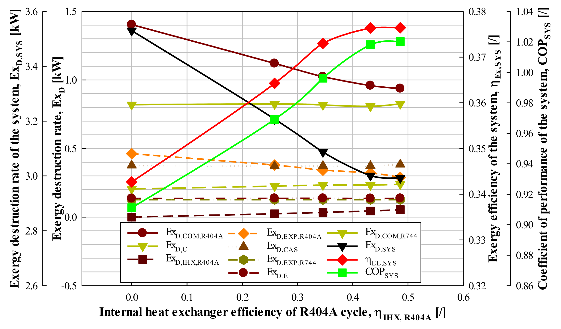
3.4.1. Effect of Internal Heat Exchanger Efficiency at R404A Cycle

An experiment was performed to find out how the exergy destruction rate and exergy efficiency of the system and each component were affected as the number of stages (i.e., increasing the efficiency) in the internal heat exchanger (IHE) in the R404A cycle increased from zero to four under the given conditions (QE = 5.15–5.18 kW, TE = −40.0–−39.8 °C, TE,CAS = −17.7–−17.4 °C, TC = 39.5–39.9 °C, ΔTCAS = 3.0–3.3 °C, ΔTSUH,R744 = 10.4–10.6 °C, ΔTSUC,R744 = 1.0–1.3 °C, ΔTSUH,R404A = 15.4–15.7 °C, ΔTSUC,R404A = 0.9–1.1 °C, ηIHX,R404A = ηIHX,R744 = 0).
As can be seen in Figure 10, as the number of stages in the IHE in the R404A cycle in the CRS increased from zero to four, the exergy destruction rate of the CRS decreased by 0.3–9.1%, and the exergy efficiency of the system increased by 0.1–6.3%. Additionally, as the number of stages of the IHE in the R404A cycle was increased from zero to four, it was confirmed that the exergy efficiency of the system increased as the COP of the system increased. In addition, as the number of stages of the IHE in the R404A cycle is increased from zero to four in the CRS, there is little change in the exergy destruction rate of the expansion valve, evaporator, condenser and cascade heat exchanger in the R744 cycle. Additionally, the exergy destruction rates in the expansion valve and compressor in the R404A cycle (ExD,EXP,R404A, ExD,COM,R404A) decreased by 6.1–18.2% and 2.2–20.1%, respectively, and the exergy destruction of the condenser and IHE efficiency in the R404A cycle (ExD,C, ExD,IHX,R404A) increased by 0.4 to 10.1% and 21.4 to 42.5%, respectively (the part increasing from 0 to 1 is omitted because the IHX efficiency is 0 when it is 0).
The reason for this result is that as the number of stages of the IHE in the R404A cycle is increased, there is no change in the exergy destruction rate because there is no change in the specific enthalpy and entropy of the inlet and outlet of the compressor, condenser, and expansion valve in the R744 cycle, and there is no change in the mass flow rate. Additionally, as the number of IHE stages in the R404A cycle is increased, the exergy destruction rate of the cascade heat exchanger (ExD,CAS) remains constant without change in the specific enthalpy and entropy difference between the inlet and outlet in the cascade condenser and the amount of condensation heat in the cascade evaporator. Although the difference increases, the mass flow rate decreases correspondingly due to energy balance, so the heat of evaporation does not change. That is, in the cascade heat exchanger, the exergy destruction rate at the inlet and outlet of the cascade evaporator (ExF,CAS: +) and the exergy destruction rate at the inlet and outlet of the cascade condenser (ExP,CAS: −) are almost the same. In addition, the exergy destruction rate of the compressor and expansion valve in the R404A cycle decreased with the decrease in the mass flow rate.
As the number of stages of the IHE in the R404A cycle is increased, both the exergy destruction rate by the refrigerant at the inlet and outlet of the R404A condenser (ExF,C: +) and the exergy destruction rate by the heat of condensation (ExP,C: −) decrease, but it was found that the exergy destruction rate of the condenser in the R404A cycle (ExD,C) increased because the decrease rate of ExP,C was greater than the decrease rate of ExF,C.
Finally, as before, the exergy destruction rate of the IHE in the R404A cycle (ExD,IHX,R404A) is the sum of the inlet/outlet exergy destruction rate in the IHE of the high-pressure and low-pressure side of the R404A cycle (ExF,IHX,R404A: +, ExP,IHX,R404A: −). As the number of stages of IHE in the R404A cycle increases, both ExF,IHX,R404A and ExP,IHX,R404A increase, but the increase rate of ExP,IHX,R404A is smaller than the increase rate of ExF,IHX,R404A, so it is judged that ExD,IHX,R404A increases. Here, the reason that the ExD,IHX,R404A increased despite the decrease in the mass flow rate in the R404A cycle is because the increase rate of ExP,IHX,R404A has a greater effect than the effect of the decrease in the mass flow rate.
Therefore, in this study, it can be concluded that the exergy destruction rate of the CRS decreases and the exergy efficiency of the system increases as the IHE with high efficiency is used in the R404A cycle.

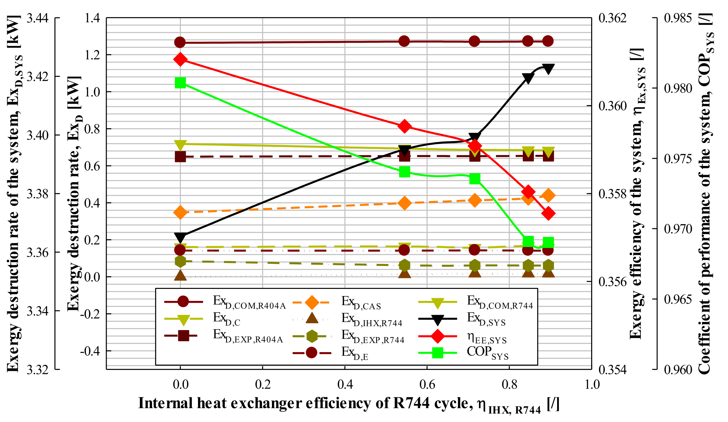
3.4.2. Effect of Internal Heat Exchanger Efficiency at R744 Cycle

An experiment was performed to find out how the exergy destruction rate and exergy efficiency of the CRS and each component were shown as the number of stages of the IHE in the R744 cycle was increased from zero to four under the given conditions (QE = 5.15–5.18 kW, TE = −40.0–−39.8 °C, TE,CAS = −17.7–−17.4 °C, TC = 39.5–39.9 °C, ΔTCAS = 3.0–3.3 °C, ΔTSUH,R404A = 15.4–15.7 °C, ΔTSUC,R404A = 0.9–1.1 °C, ΔTSUH,R744 = 10.4–10.6 °C, ΔTSUC,R744 = 1.0~1.3 °C, ηIHX,R404A = ηIHX,R744 = 0).
As can be seen in Figure 11, as the number of stages of the IHE in the R744 cycle of the CRS increased from zero to four, the exergy destruction rate of the system increased by 0.1–1%, and the exergy efficiency of the system was decreased by 0.1–0.4%. Additionally, it was confirmed that the exergy efficiency of the system decreased as the COP of the system decreased. In addition, as the number of stages of the IHE in the R744 cycle is increased from zero to four in the CRS, there is little change in the exergy destruction rate of the compressor, condenser, and expansion valve in the R404A cycle and the evaporator in the R744 cycle, and the exergy destruction rates of the expansion valve and compressor in the R744 cycle (ExD,EXP,R744, ExD,COM,R744) decreased by 0.2–26.9% and 0.3–3.5%, respectively.
Additionally, the exergy destruction rate of the IHE and the cascade heat exchanger in the R744 cycle (ExD,IHX,R744, ExD,CAS) increased by 0.1 to 25.5% and 2.5 to 14.7%, respectively.
The reason for this result is that as the number of stages of the IHE in the R744 cycle is increased, there is no change in the exergy destruction rate because there is no change in the specific enthalpy and entropy of the inlet and outlet of the compressor, condenser, and expansion valve in the R404A cycle, and there is no change in mass flow. So, there is also no change in the exergy destruction rate. Additionally, because the evaporation capacity is almost constant, the mass flow rate of the R744 cycle decreases, but the difference between specific enthalpy and entropy of the evaporator inlet and outlet increases correspondingly. Therefore, it is judged that the exergy destruction rate is almost the same as the change in evaporation capacity. That is, since the rate of increase and decrease in the refrigerant exergy destruction rate of the R744 evaporator (ExF,E: +) is the same as the rate of increase/decrease in the exergy destruction rate by the evaporation capacity (ExP,E: −), the exergy destruction rate of the R744 evaporator (ExD,E) is considered to be constant.
As the number of stages of the IHE increases, the difference between specific enthalpy and entropy of the inlet and outlet in the expansion valve and compressor in the R744 cycle increases. While this increase is very small, it is thought that the exergy destruction rate of the expansion valve and the compressor in the R744 cycle decreases because the effect of the decrease in the mass flow rate of the R744 cycle is large. In addition, as the number of stages of the IHE in the R744 cycle increases, the exergy destruction rate of both the cascade evaporator (ExF,CAS: +) and the cascade condenser (ExP,CAS: −) decreases, but the reduction ratio of ExP,CAS is larger than the reduction ratio of ExF,CAS, so the exergy destruction rate of the cascade heat exchanger (ExD,CAS) is considered to increase.
Additionally, the exergy destruction rate of the IHE in the R744 cycle (ExD,IHX,R744) is almost the same as the exergy destruction rate calculation method of the cascade heat exchanger. That is, the exergy destruction rate of the IHE in the R744 cycle is the sum of the exergy destruction rate in the inlet/outlet of the IHE at the low-pressure side (ExF,IHX,R744: +) and the exergy destruction rate in the inlet/outlet of IHE at the high-pressure side (ExP,IHX,R744: −). As the number of stages of the IHE increases, both ExF,IHX,R744 and ExP,IHX,R744 increase, but the increase rate of ExP,IHX,R744 is smaller than the increase rate of ExF,IHX,R744, so ExD,IHX,R744 is considered to be increasing. Here, the reason that ExD,IHX,R744 increases even though the mass flow rate of the R744 cycle decreases means that the increase rate of ExP,IHX,R744 has a greater effect than the effect of the decrease in the mass flow rate. Therefore, it can be concluded that as the number of stages of IHE in the R744 cycle of the CRS increases, the exergy destruction rate of the system increases and the exergy efficiency of the system decreases.
Figure 4, Figure 5, Figure 6, Figure 7, Figure 8, Figure 9, Figure 10 and Figure 11 show the relationship between the total exergy destruction rate (ExD,SYS), the COP (COPSYS), and the exergy efficiency (ηEx,SYS) of the R744/R404A CRS according to each experimental condition. It was shown that the exergy destruction rate and COP of this system had an inverse relationship, and it was confirmed that the exergy efficiency and COP of the system had the same trend.
Therefore, in order to increase the COP of the R744/R404A CRS, efforts should be made to reduce the exergy destruction rate of each component.

3.5. Comparison of Experimental and Pereformance Analysis Data

Figure 5 shows the exergy destruction rate of each component (ExD) and exergy destruction rate (ExD,SYS), exergy efficiency (ηEx,SYS) and COP (COPSYS) of the CRS of according to the superheating degree at the R404A cycle of the CRS. It is displayed as data obtained through the performance analysis, and Figure 12 shows the results obtained through performance analysis.
Figure 5 was carried out under the given conditions (QE = 5.69–5.71 kW, TE = -40.0–-39.8 °C, TE,CAS = −24.6–−24.3 °C, TC = 39.8–40.0 °C, ΔTSUC,R404A = 0.6–1.3 °C, ΔTSUH,R744 = 40.0–40.6 °C, ΔTSUC,R744 = 2.1–2.3 °C, ΔTCAS = 2.9–3.3 °C, ηIHX,R404A = ηIHX,R744 = 0), and Figure 12 is the result obtained under the given conditions (QE = 5.69 kW, TE = −40 °C, TE,CAS = −24.5 °C, TC = 40.0 °C, ΔTCAS = 3.1 °C, ΔTSUH,R744 = 10 °C, ΔTSUC,R744 = 2.2 °C, ΔTSUC,R404A = 1 °C, ηCOM,R744 = 0.499, ηCOM,R404A = 0.485, ηIHX,R404A = ηIHX,R744 = 0). The analysis conditions in Figure 12 were adjusted to be the same as the conditions of the experimental data as much as possible. The results of the performance analysis according to the conditions show that the reduction rate of the exergy destruction rate according to the power consumption of the R404A compressor was smaller than the results of the experimental data. Therefore, the reduction rate of the exergy destruction rate of the entire system was also small, and it appeared almost the same except for the exergy destruction rate of the R404A compressor. Additionally, the trend of COP and exergy efficiency of the system appeared the same.
In addition to the effect of superheating degree of the R404A cycle as shown in Figure 5 and Figure 12, the exergy destruction rate of each component and exergy destruction rate, exergy efficiency, and COP of the system (ExD, ExD,SYS, ηEx,SYS, COPSYS) in accordance with the subcooling degree of R404A cycle, superheating degree of R744 cycle, evaporation temperature, condensation temperature, cascade evaporation temperature, and IHE efficiency were also compared. It was confirmed that all of them showed the same results.

4. Conclusions

This paper examines the exergy efficiency and exergy destruction rate of the R744/R404A CRS using an IHE in supermarkets according to various conditions (degree of subcooling and superheating, cascade evaporation temperature, condensation and evaporation temperature, and IHE efficiency, etc.) affecting the system. The results are as follows.
  • The COP, exergy efficiency, and exergy destruction rate of a CRS have a close relationship. The lower the total exergy destruction rate of the system, the higher the exergy efficiency of the system and accordingly the COP of the system is also improved.
  • In the CRS, since the optimum cascade evaporation temperature exists (about −16 °C), it can be said that the limit point, that is, the cascade evaporation temperature with the maximum COP of the system, is the optimum point at about −16 °C. Therefore, at this optimum point (i.e., optimum cascade evaporation temperature or evaporation pressure), the exergy destruction rate of the cascade heat exchanger is at its minimum value. In other words, it should be noted that when the cascade evaporation temperature is the optimum point, the exergy destruction rate of the R744 compressor and the cascade heat exchanger is minimal.
  • In case R404A with high GWP cannot be applied, R448A and R449A, which can be replaced one-to-one with R404A, are recommended as alternative refrigerants for R404A.

Funding

This research received no external funding.

Data Availability Statement

Not applicable.

Conflicts of Interest

The authors declare no conflict of interest.

Nomenclature

Symbols
COPCoefficients of performance
E x ˙ Exergy rate (kW)
iSpecific enthalpy (kJ/kg)
m ˙ Mass flow rate (kg/s)
PPressure (kPa)
QHeat capacity (kW)
sSpecific entropy (kJ/(kg·K))
TTemperature (°C)
WPower consumption (kW)
Greek Symbols
Δ Difference
ηEfficiency
Superscripts
MMechanical
TThermal
Subscripts
CCondensation, Condenser
CASCascade heat exchanger
COMCompressor
DDestruction
EEvaporation, Evaporator
E x ˙ Exergy
FFuel
IHXInternal heat exchanger
kkth compenent
PProduct
RatioRatio
R404AR404A refrigeration cycle
R744R744 refrigeration cycle
SUCSubcooling
SUHSuperheating
SYSCascade refrigeration system

References

  1. Sawalha, S. Using CO2 in supermarket refrigeration. ASHRAE 2005, 47, 26–30. [Google Scholar]
  2. Veiby, O.J. Internal Records, Documentation in the ICA Supermarket Chain in Norway. Oslo, Norway, 2003.
  3. Queiroz, M.V.A.; Panato, V.H.; Antunes, A.H.P.; Parise, J.A.R.; Bandarra Filho, E.P. Experimental comparison of a cascade refrigeration system operating with R744/R134a and R744/R404A. In Proceedings of the International Refrigeration and Air-Conditioning Conference at Purdue, West Lafayette, IN, USA, 11–14 July 2016; pp. 1–10. Available online: http://docs.lib.purdue.edu/iracc/1785 (accessed on 7 November 2016).
  4. Lee, T.-S.; Liu, C.-H.; Chen, T.-W. Thermodynamic analysis of optimal condensing temperature of cascade-condenser in CO2/NH3 cascade refrigeration systems. Int. J. Refrig. 2006, 29, 1100–1108. [Google Scholar] [CrossRef]
  5. Gholamian, E.; Hanafizadeh, P.; Ahmadi, P. Advanced exergy analysis of a carbon dioxide ammonia cascade refrigeration system. Appl. Therm. Eng. 2018, 137, 689–699. [Google Scholar] [CrossRef]
  6. Aminyavari, M.; Najafi, B.; Shirazi, A.; Rinaldi, F. Exergetic, economic and environmental (3E) analyses, and multiobjective optimization of a CO2/NH3 cascade refrigeration system. Appl. Therm. Eng. 2014, 65, 42–50. [Google Scholar] [CrossRef]
  7. Rangel, V.B.; Almeida, A.G.S. Cascade refrigeration system for low temperatures using natural fluids. Therm. Eng. 2021, 20, 20–26. [Google Scholar] [CrossRef]
  8. Pan, M.; Zhao, H.; Liang, D.; Zhu, Y.; Liang, Y.; Bao, G. A review of the cascade refrigeration system. Energies 2020, 13, 2254. [Google Scholar] [CrossRef]
  9. Sun, Z.; Wang, Q.; Xie, Z.; Liu, S.; Su, D.; Cui, Q. Energy and exergy analysis of low GWP refrigerants in cascade refrigeration system. Energy 2019, 170, 1170–1180. [Google Scholar] [CrossRef]
  10. Roy, R.; Mandal, B.K. Energetic and exergetic performance comparison of cascade refrigeration system using R170/R161 and R41/R404A as refrigerant pairs. Heat Mass Transf. 2019, 55, 723–731. [Google Scholar] [CrossRef]
  11. Kumar, V. Comparative analysis of cascade refrigeration system based on energy and exergy using different refrigerant pairs. J. Therm. Eng. 2020, 6, 106–116. [Google Scholar] [CrossRef] [Green Version]
  12. Zhang, Y.; He, Y.; Wang, Y.; Wu, X.; Jia, M.; Gong, Y. Experimental investigation of the performance of an R1270/CO2 cascade refrigerant system. Int. J. Refrig. 2020, 114, 175–180. [Google Scholar] [CrossRef]
  13. Jeon, M.J. Experimental analysis of the R744/R404A cascade refrigeration system with internal heat exchanger. Part 1: Coefficient of performance characteristics. Energies 2021, 14, 6003. [Google Scholar] [CrossRef]
  14. Ahern, J.E. Exergy Method of Energy Systems Analysis; John Wiley and Sons: New York, NY, USA, 1980. [Google Scholar]
  15. Bai, T.; Yu, J.; Yan, G. Advanced exergy analysis on a modified auto-cascade freezer cycle with an ejector. Energy 2016, 113, 385–398. [Google Scholar] [CrossRef]
  16. Vatani, A.; Mehrpooya, M.; Palizdar, A. Advanced exergetic analysis of five natural gas liquefaction processes. Energy Convers. Manag. 2014, 78, 720–737. [Google Scholar] [CrossRef]
  17. Morosuk, T.; Tsatsaronis, G. Graphical models for splitting physical exergy. In Proceedings of the ECOS 2005-Proceedings of the 18th International Conference on Efficiency, Cost, Optimization, Simulation, and Environmental Impact of Energy Systems, Trondheim, Norway, 20–22 June 2005; Tapir Academic Press: Trondheim, Norway, 2005; pp. 377–384. [Google Scholar]
  18. Morosuk, T.; Tsatsaronis, G.; Zhang, C. Conventional thermodynamic and advanced exergetic analysis of a refrigeration machine using a Voorhees’ compression process. Energy Convers. Manag. 2012, 60, 143–151. [Google Scholar] [CrossRef]
  19. Lazzaretto, A.; Tsatsaronis, G. SPECO: A systematic and general methodology for calculating efficiencies and costs in thermal systems. Energy 2006, 31, 1257–1289. [Google Scholar] [CrossRef]
  20. Bejan, A.; Tsatsaronis, G.; Moran, M. Thermal Design and Optimization; John Wiley & Sons: New York, NY, USA, 1996. [Google Scholar]
  21. Tsatsaronis, G. Definitions and nomenclature in exergy analysis and exergoeconomics. Energy 2007, 32, 249–253. [Google Scholar] [CrossRef]
  22. Sun, Z.; Liang, Y.; Liu, S.; Ji, W.; Zang, R.; Liang, R.; Guo, Z. Comparative analysis of thermodynamic performance of a cascade refrigeration system for refrigerant couples R41/R404A and R23/R404A. Appl. Energy 2016, 184, 19–25. [Google Scholar] [CrossRef]
  23. Morosuk, T.; Tsatsaronis, G. Advanced exergetic evaluation of refrigeration machines using different working fluids. Energy 2009, 34, 2248–2258. [Google Scholar] [CrossRef]
  24. Kline, S.J.; McClintock, F.A. Describing Uncertainties in Single Sample Experiments. Mech. Eng. 1953, 75, 3–8. [Google Scholar]
  25. Moffat, R. Describing the uncertainties in experimental results. Exp. Therm. Fluid Sci. 1988, 1, 3–17. [Google Scholar] [CrossRef] [Green Version]
  26. Yılmaz, D.; Sınar, Ü.; Özyurt, A.; Yılmaz, B.; Mancuhan, E. Ultra Düşük Sıcaklıklarda Çalışan İki Kademeli Bir Soğutma Sisteminde Aşırı Soğutma ve Isıtmanın Performansa Etkilerinin Sayısal İncelenmesi. Afyon Kocatepe Univ. J. Sci. Eng. 2017, 17, 1172–1180. [Google Scholar] [CrossRef]
  27. Mosaffa, A.H.; Garousi Farshi, L.; Infante Ferreira, C.A.; Rosen, M.A. Exergoeconomic and environmental analyses of CO2/NH3 cascade refrigeration systems equipped with different types of flash tank intercoolers. Energy Convers. Manag. 2016, 117, 442–453. [Google Scholar] [CrossRef] [Green Version]
  28. Hendri; Nurhasanah, R.; Prayudi; Suhengki. Energy and Exergy Analysis of Cascade Refrigeration System Using MC22 and MC134 on HTC, R404A and R502 on LTC. J. Adv. Res. Fluid Mech. Therm. Sci. 2021, 80, 73–83. [Google Scholar] [CrossRef]
  29. Parekh, A.D.; Tailor, P.R. Thermodynamic analysis of cascade refrigeration, system using R12-R13, 290-R23 and R404A-R23. World Acad. Sci. Eng. Technol. Int. J. Mech. Mechatron. Eng. 2014, 8, 1351–1356. [Google Scholar]
  30. Kilicarslan, A.; Hosoz, M. Energy and irreversibility analysis of a cascade refrigeration system for various refrigerant couples. Energy Convers. Manag. 2010, 51, 2947–2954. [Google Scholar] [CrossRef]
  31. Yilmaz, F.; Selbaş, R. Comparative thermodynamic performance analysis of a cascade system for cooling and heating applications. Int. J. Green Energy 2019, 16, 674–686. [Google Scholar] [CrossRef]
  32. Dokandari, D.A.; Hagh, A.S.; Mahmoudi, S.M.S. Thermodynamic investigation and optimization of novel ejector-expansion CO2/NH3 cascade refrigeration cycles (novel CO2/NH3 cycle). Int. J. Refrig. 2014, 46, 26–36. [Google Scholar] [CrossRef]
  33. Dopazo, J.A.; Fernández-Seara, J.; Sieres, J.; Uhía, F.J. Theoretical analysis of a CO2-NH3 cascade refrigeration system for cooling applications at low temperatures. Appl. Therm. Eng. 2009, 29, 1577–1583. [Google Scholar] [CrossRef] [Green Version]
Figure 1. Photograph of the experimental apparatus for the CRS using R744.
Energies 15 01251 g001
Figure 2. Schematic diagram of experimental apparatus for the CRS using R744. [13].
Energies 15 01251 g002
Figure 3. The conceptual diagram of the R744/R404A CRS.
Energies 15 01251 g003
Figure 4. Exergy destruction rate, exergy efficiency and COP of the CRS with respect to subcooling degree of R404A cycle.
Energies 15 01251 g004
Figure 5. Exergy destruction rate, exergy efficiency and COP of the CRS with respect to superheating degree of R404A cycle.
Energies 15 01251 g005
Figure 6. Exergy destruction rate, exergy efficiency and COP of the CRS with respect to superheating degree of R744 cycle.
Energies 15 01251 g006
Figure 7. Exergy destruction rate, exergy efficiency and COP of the CRS with respect to condensation temperature of the CRS.
Energies 15 01251 g007
Figure 8. Exergy destruction rate, exergy efficiency and COP of the CRS with respect to the evaporation temperature of the CRS.
Energies 15 01251 g008
Figure 9. Exergy destruction rate, exergy efficiency and COP of the CRS with respect to the evaporation temperature of the cascade heat exchanger.
Energies 15 01251 g009
Figure 10. Exergy destruction rate, exergy efficiency and COP of the CRS with respect to the IHE efficiency of the R404A cycle.
Energies 15 01251 g010
Figure 11. Exergy destruction rate, exergy efficiency and COP of the CRS with respect to the IHE efficiency of the R744 cycle.
Energies 15 01251 g011
Figure 12. Performance analysis results with respect to superheating degree in the R404A cycle of the CRS.
Energies 15 01251 g012
Table 1. Advantages of R744 as refrigerant or brine.
Advantages of R744
  • Little impact on the global environment (ODP = 0, GWP = 1)
  • No toxicity and flammability
  • General metal materials can be used.
  • The price of refrigerant is cheap.
  • Due to the large latent heat of evaporation at low temperature, the required amount of refrigerant circulation can be reduced, and the tube diameter can be reduced.
  • Because of the small viscosity, the consumption power for transportation is reduced.
Table 2. Experimental conditions of the CRS [13].
CycleComponentRangeUnit
High-temperature cycle
(R404A)
Condensation temperature20, 30, 40 *, 50°C
Internal heat exchanger efficiency0 *, 1, 2, 3, 4stage
Subcooling degree0 *, 5, 10, 15, 20°C
Superheating degree10, 20 *, 30, 40°C
Evaporation temperature−30, −25 *, −20, −15, −10°C
Temperature difference of cascade heat exchanger5°C
Low-temperature cycle
(R744)
Condensation temperature−25, −20 *, −15, −10, −5°C
Internal heat exchanger efficiency0 *, 1, 2, 3, 4stage
Subcooling degree2 *°C
Superheating degree10, 20, 30, 40 *°C
Evaporation temperature−50, −45, −40 *, −35, −30°C
*: Standard conditions.
Table 3. Main components of the experimental apparatus for the CRS. [13].
ComponentCharacteristics
Evaporator


Condenser
Cascade heat exchanger
R404A compressor

R744 compressor
Hand-made, type: horizontal double tube, material: copper tube, internal diameter of inner tube: 11.46mm, internal diameter of outer tube: 33.27 mm, length of the evaporator: 8000 mm
Alfa Laval, model: ACH-70X-50H-F, heat exchanged: 38.44 kW, heat transfer area: 2.45 m2
Alfa Laval, model: ACH-70X-50H-F, heat exchanged: 10.86 kW, heat transfer area: 2.45 m2
Bock, model: HGX34P/380-4S. Displacement with 1450 min−1: 33.1 m3h−1, no. of cylinders: 4, weight: 96 kg, max. power consumption: 11.1 kW
Bock, model: HGX12P/40-4. Displacement with 1450 min−1: 4.4 m3h−1, no. of cylinders: 2, weight: 53 kg, max. power consumption: 2.1 kW
Table 4. Entropy and exergy balance equation for each component of the CRS using R744 and R404A [15,22,23].
CycleComponent E x ˙ F , k ,   kW E x ˙ P , k ,   kW E x ˙ D , k ,   kW
High
Temperature
Cycle
(R404A)
Compressor (1→2) W C O M , R 404 A E x ˙ 2 E x ˙ 1 W C O M , R 404 A ( E x ˙ 2 E x ˙ 1 )
Condenser (2→4) E x ˙ 2 E x ˙ 4 Q c 1 T 0 T C ( E x ˙ 2 E x ˙ 4 ) Q c 1 T 0 T C
Internal heat exchanger (4→5, 8→1) E x ˙ 4 E x ˙ 5 E x ˙ 8 E x ˙ 1 ( E x ˙ 4 E x ˙ 5 ) ( E x ˙ 8 E x ˙ 1 )
Expansion valve (5→6) E x ˙ 5 M E x ˙ 6 M E x ˙ 6 T E x ˙ 5 T ( E x ˙ 5 M E x ˙ 6 M ) ( E x ˙ 6 T E x ˙ 5 T )
Cascade heat exchanger (6→8, 12→14) E x ˙ 6 E x ˙ 8 E x ˙ 14 E x ˙ 12 ( E x ˙ 6 E x ˙ 8 ) ( E x ˙ 14 E x ˙ 12 )
Low
Temperature
Cycle
(R744)
Compressor (11→12) W C O M , R 744 E x ˙ 12 E x ˙ 11 W C O M , R 744 ( E x ˙ 12 E x ˙ 11 )
Internal heat exchanger (14→15, 18→11) E x ˙ 18 E x ˙ 11 E x ˙ 15 E x ˙ 14 ( E x ˙ 18 E x ˙ 11 ) ( E x ˙ 15 E x ˙ 14 )
Expansion valve (15→16) E x ˙ 15 M E x ˙ 16 M E x ˙ 16 T E x ˙ 15 T ( E x ˙ 15 M E x ˙ 16 M ) ( E x ˙ 16 T E x ˙ 15 T )
Evaporator (16→18) E x ˙ 16 E x ˙ 18 Q E T 0 T E + Δ T E 1 ( E x ˙ 16 E x ˙ 18 ) Q E T 0 T E + Δ T E 1
Table 5. Parameters and estimated uncertainties.
ParametersUnitUncertainty
Mass flow rate [kg/min]±0.01
COP of cascade refrigeration system[/]±0.0135
Exergy destruction rate of system [kW]±0.0175
Temperature [oC]±0.20
Δ T C A S [oC]±0.40
Pressure [kPa]±5.27
Δ P (Pressure drop)[kPa]±0.01
Mass flow rate of coolant[kg/h]±7.53
Publisher’s Note: MDPI stays neutral with regard to jurisdictional claims in published maps and institutional affiliations.

