
Roof Hydraulic Fracturing for Preventing Floor Water Inrush under Multi Aquifers and Mining Disturbance: A Case Study


Abstract
:1. Introduction
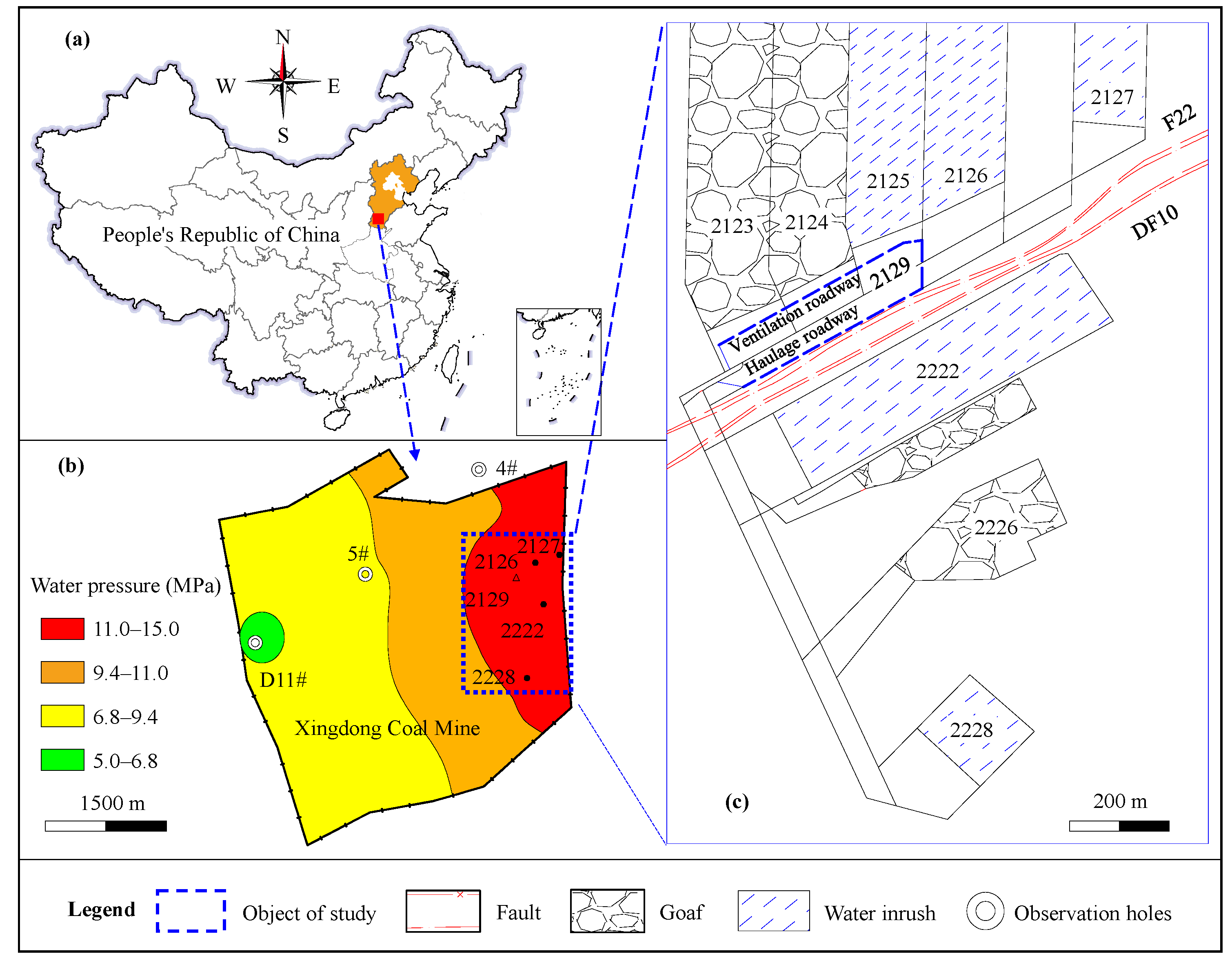
2. Study Area
2.1. Overview of the Mine and Panel 2129
2.2. Geologic Characteristics
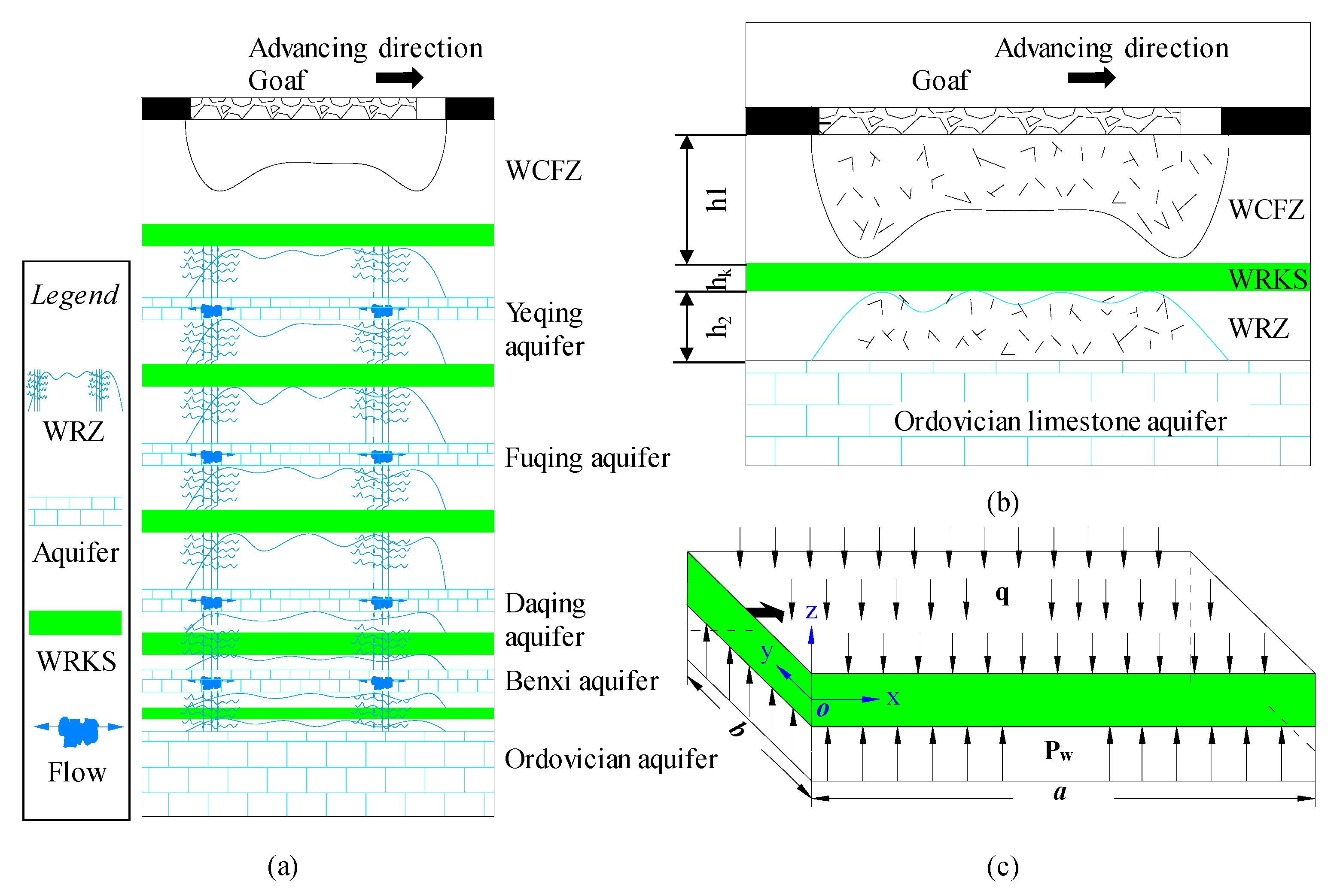
2.3. Characteristics of Floor Water Inrush
3. Mechanism Analysis of Floor Water Inrush
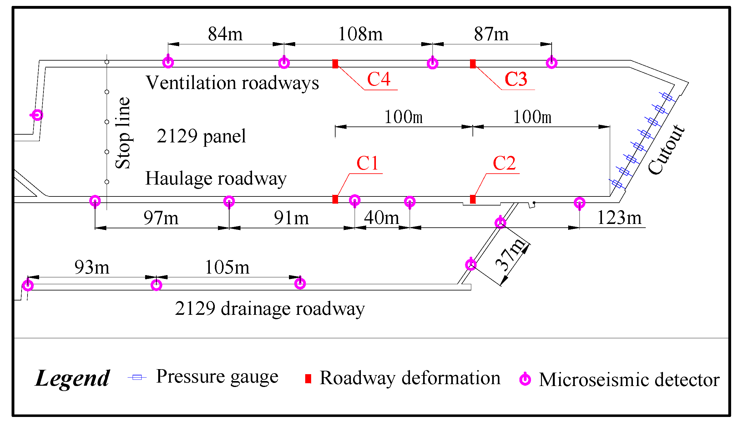
4. Prevention Methods and Effect Evaluation of Floor Water Inrush
4.1. Roof Hydraulic Fracturing
4.2. Multi-Parameter Effect Evaluation
5. Results and Discussion
5.1. Effective Verification of RHF
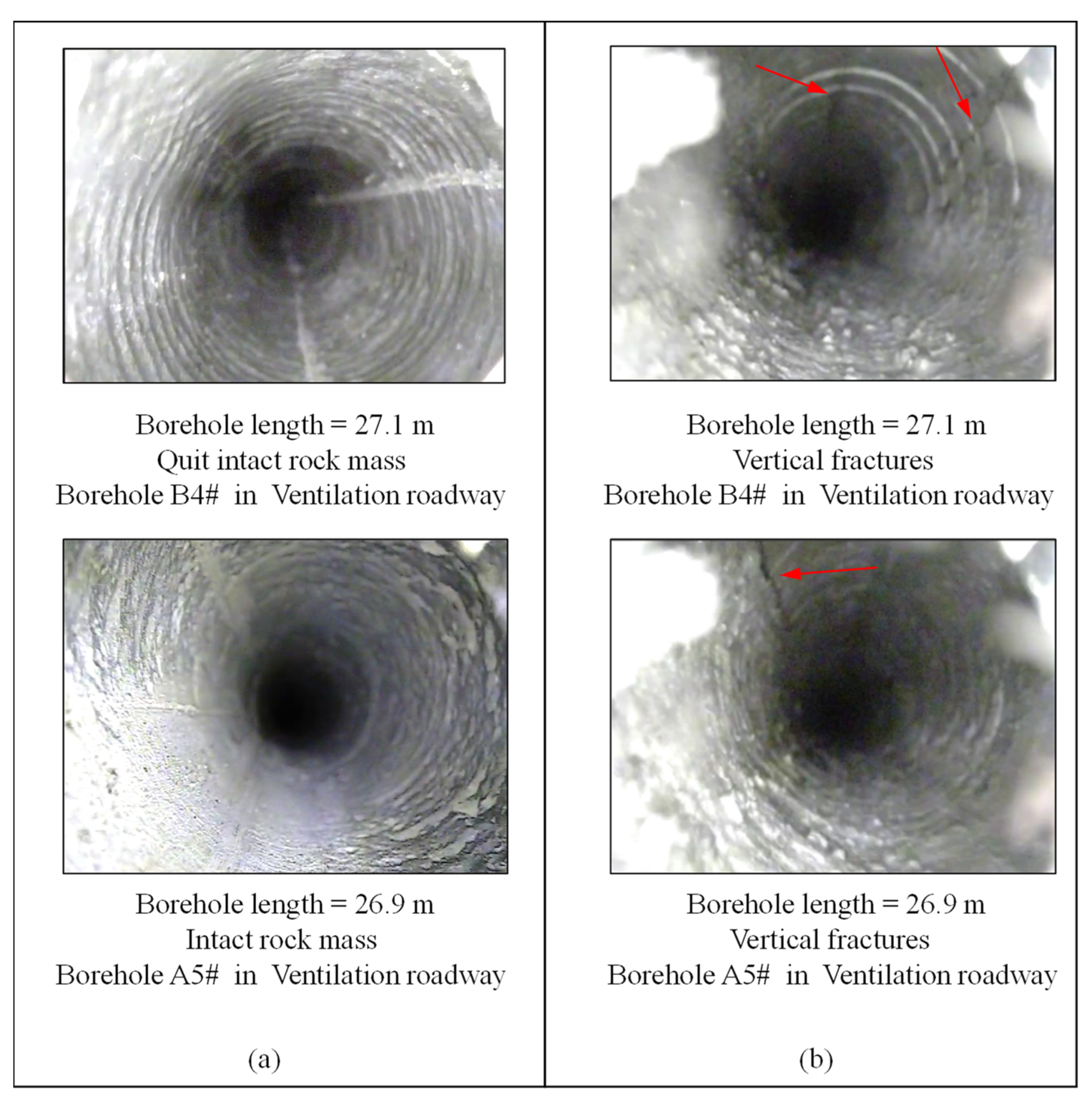
5.1.1. Hydraulic Fracturing Fractures
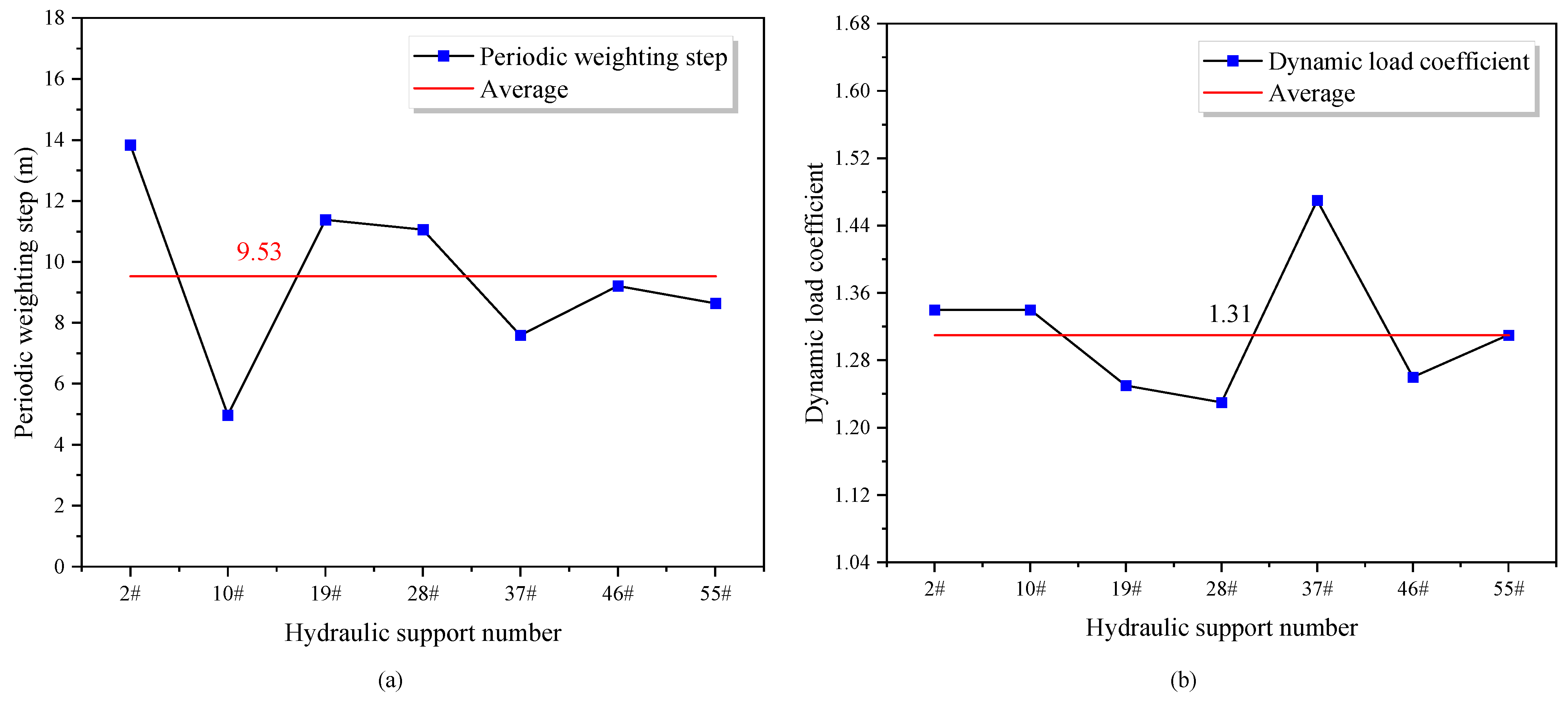
5.1.2. Mining Face Support Stress
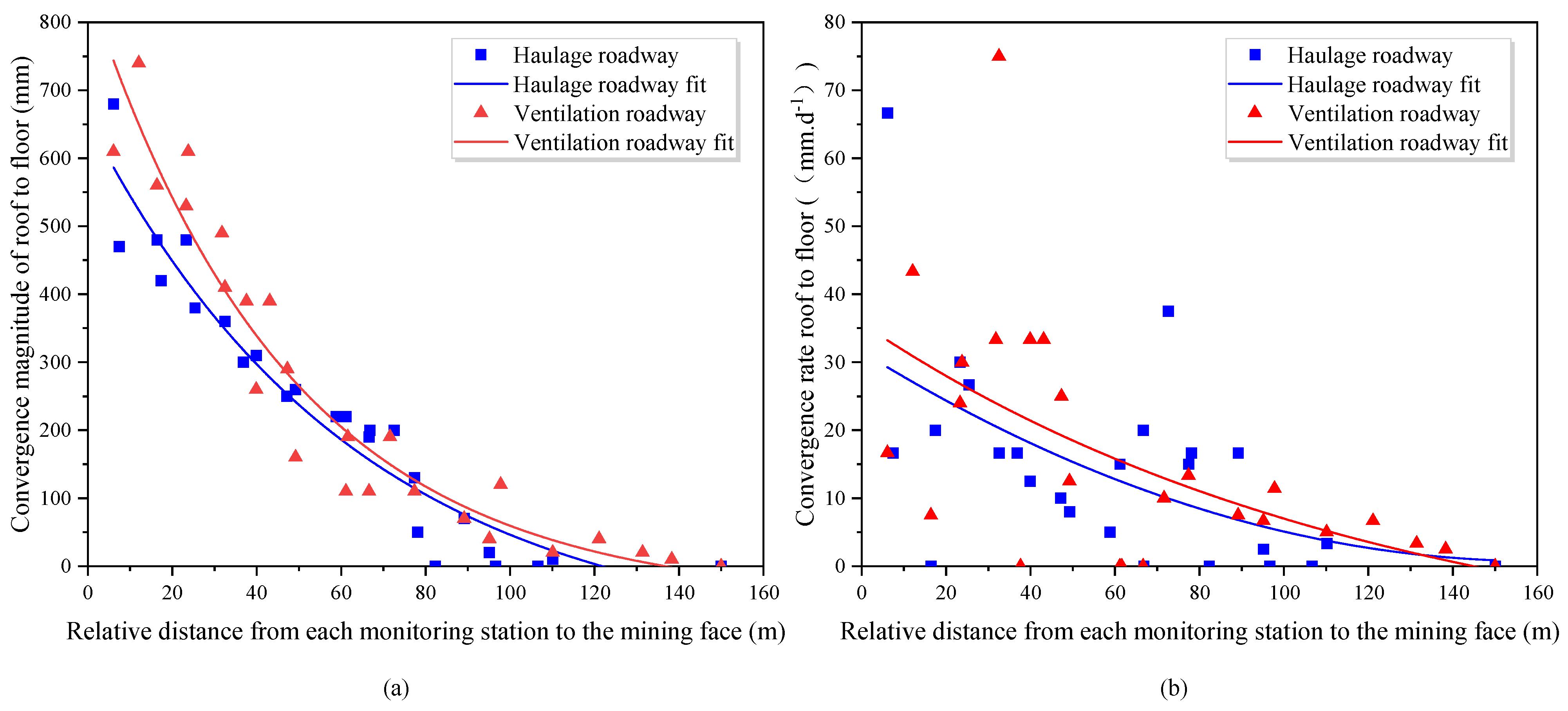
5.1.3. Roof-to-Floor Convergence
5.1.4. Water Level
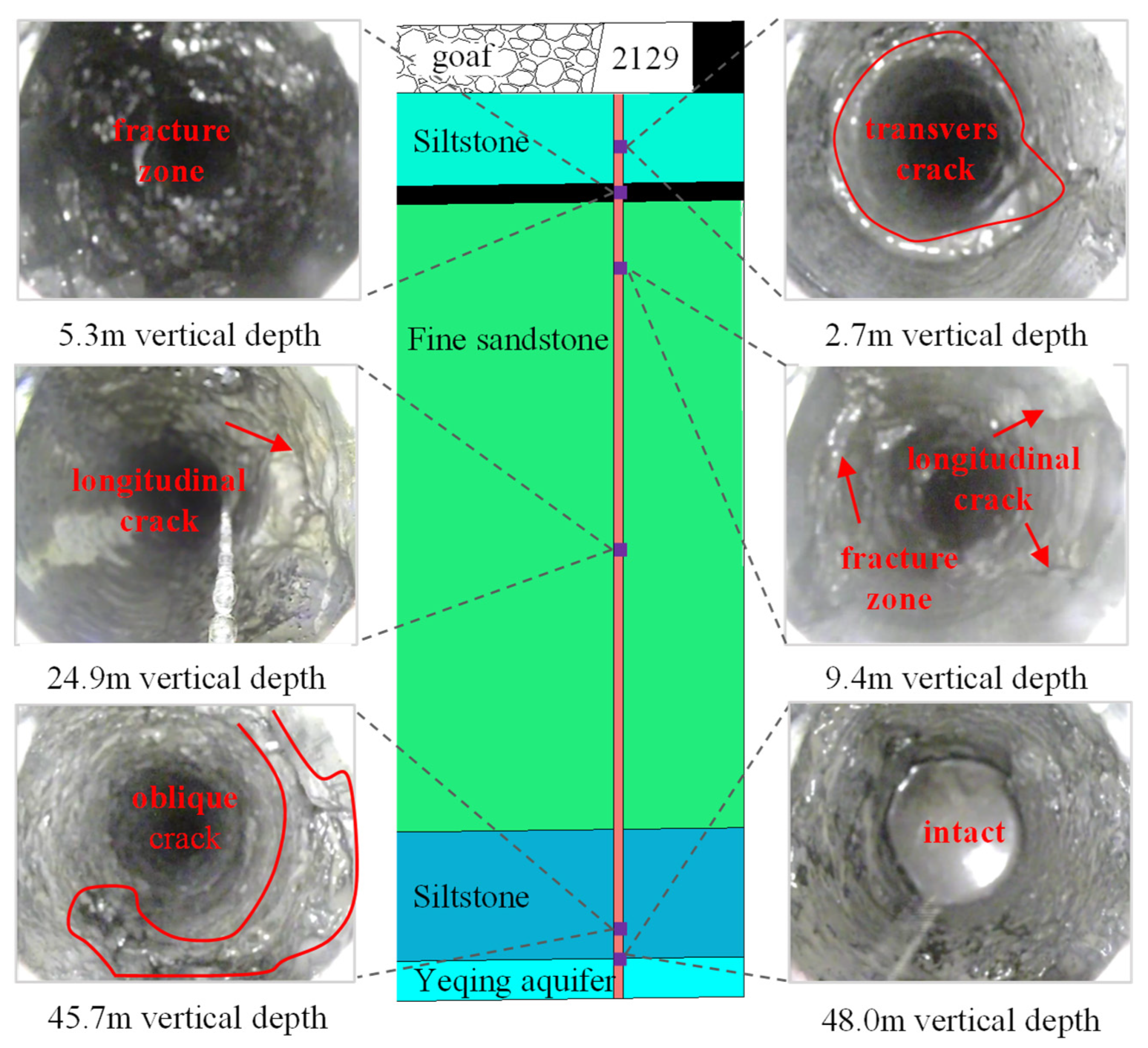
5.1.5. Water Conducting Channel Evolution
5.2. Assessment of Water Inrush Risk
5.3. Mechanism of RHF to Prevent Floor Water Inrush
- (1)
- The high abutment pressure induced by coal seam mining can generate high stress in the floor [46,50]. The cracks in the floor under the stress concentration area are deeply developed, which easily form a concentrated water-conducting channel [8]. RHF reduces the weighting step, the roof hanging distance and the magnitude of abutment pressure. Thus, the depth and intensity of the stress disturbance in the floor caused by the high abutment pressure are greatly decreased;
- (2)
- The unloading range and degree of the floor in the goaf decreased after RHF. The floor strata in the unloading zone were loaded in time to shorten the unloading time. The unloading damage range decreased because the floor stress in the mined zone recovered in time. With the increasing load in the mined-out area, the ultimate water pressure that the WRKS can withstand increases, indicating that deformations and fractures can be compressed and closed by the collapsed roof rock, as described by Sun et al. [22];
- (3)
- With the decrease in stress concentration and unloading degree in the floor, the floor failure depth decreased. The fractures in the floor did not extend to deep rock mass, resulting in a lower probability of conduction within the hydraulic fractures or hidden structures in the floor. The higher the stress in the floor of the mining area, the smaller the degree of unloading in the mining area, and the smaller the unloading failure depth of the floor [50,51].
5.4. Further Discussion and Implications
6. Conclusions
- (1)
- The mechanism of floor water inrush with multiple aquifers in deep mining is that the Ordovician limestone water connects with thin limestone water, and then the WRKS penetrates layer by layer. The uppermost WRKS is broken, and floor water inrush occurs. We found that reducing the mining stress could maintain the stability of the WRKS in the floor. Shortening the roof weighting step, reducing the unloading size of the goaf, decreasing the mining failure depth of the floor and increasing the thickness of the WRKS were suitable control measures. Therefore, RHF prevention technology was proposed;
- (2)
- The average periodic weighting step was 9.53 m after RHF, which was 61.42% less than that of panel 2222 without RHF, adjacent to panel 2129. The maximum convergence rate of the roof to the floor in the hydraulic fracturing section was 75 mm/d. These results indicated that the disturbance of the surrounding rock caused by coal mining was significantly less than that of the working face without RHF. The floor failure depth was 30 m after RHF, which was 34.4% less than the section without RHF (45.7 m). The critical water pressure of the WRKS (15.11 MPa) exceeded the actual water pressure (12.96 MPa) by 2.15 MPa when the length of the unloading zone was 93 m. The results revealed that the floor water-conducting channel was undeveloped due to the reduction in mining disturbance after RHF;
- (3)
- This study demonstrates that comprehensive techniques to control floor water inrush are needed under complex geological conditions in deep mining. RHF is an optional method to prevent floor water inrush in deep mining, especially in complex geological and mining conditions such as hard roof, island working face and isolated coal pillar.
Author Contributions
Funding
Data Availability Statement
Conflicts of Interest
References
- Wu, Q.; Fan, S.; Zhou, W.; Liu, S. Application of the Analytic Hierarchy Process to Assessment of Water Inrush: A Case Study for the No. 17 Coal Seam in the Sanhejian Coal Mine, China. Mine Water Environ. 2013, 32, 229–238. [Google Scholar] [CrossRef]
- Wu, Q.; Wang, M.; Wu, X. Investigations of groundwater bursting into coal mine seam floors from fault zones. Int. J. Rock Mech. Min. Sci. 2004, 41, 557–571. [Google Scholar] [CrossRef]
- Adams, R.; Younger, P.L. A strategy for modeling ground water rebound in abandoned deep mine systems. Ground Water 2001, 39, 249–261. [Google Scholar] [CrossRef] [PubMed]
- Zhao, Y.; Yang, T.; Zhang, P.; Xu, H.; Wang, S. Inversion of seepage channels based on mining-induced microseismic data. Int. J. Rock Mech. Min. Sci. 2020, 126, 104180. [Google Scholar] [CrossRef]
- Dong, S.; Liu, Z.; Zheng, S.; Wang, H.; Shi, Z.; Shang, H.; Zhao, C.; Zheng, L. Technology and application of large curtain grouting water conservation mining based on macroscopic and mesoscopic characteristics of rock mass. J. China Coal Soc. 2020, 45, 1137–1149. (In Chinese) [Google Scholar] [CrossRef]
- Li, H.; Bai, H.; Wu, J.; Ma, Z.; Ma, K.; Wu, G.; Du, Y.; He, S. A cascade disaster caused by geological and coupled hydro-mechanical factors-water inrush mechanism from karst collapse column under confining pressure. Energies 2017, 10, 1938. [Google Scholar] [CrossRef] [Green Version]
- Xie, H.; Ju, Y.; Ren, S.; Gao, F.; Liu, J.; Zhu, Y. Theoretical and technological exploration of deep in situ fluidized coal mining. Front. Energy 2019, 13, 603–611. [Google Scholar] [CrossRef]
- Li, C.; Zuo, J.; Wei, C.; Xu, X.; Zhou, Z.; Li, Y.; Zhang, Y. Fracture Development at Laminated Floor Layers Under Longwall Face in Deep Coal Mining. Nat. Resour. Res. 2020, 29, 3857–3871. [Google Scholar] [CrossRef]
- Guo, J.; Ma, L.; Zhang, D. Management and Utilization of High-Pressure Floor-Confined Water in Deep Coal Mines. Mine Water Environ. 2019, 38, 780–797. [Google Scholar] [CrossRef]
- Liu, S.; Fei, Y.; Xu, Y.; Huang, L.; Guo, W. Full-floor Grouting Reinforcement for Working Faces with Large Mining Heights and High Water Pressure: A Case Study in China. Mine Water Environ. 2020, 39, 268–279. [Google Scholar] [CrossRef]
- Zhang, E.; Xu, Y.; Fei, Y.; Shen, X.; Zhao, L.; Huang, L. Influence of the dominant fracture and slurry viscosity on the slurry diffusion law in fractured aquifers. Int. J. Rock Mech. Min. Sci. 2021, 141, 104731. [Google Scholar] [CrossRef]
- Huang, Z.; Jiang, Z.; Tang, X.; Wu, X.; Guo, D.; Yue, Z. In situ Measurement of Hydraulic Properties of the Fractured Zone of Coal Mines. Rock Mech. Rock Eng. 2016, 49, 603–609. [Google Scholar] [CrossRef]
- Meng, L.; Feng, Q.; Li, Q. Coupled simulation–optimization model for draining confined aquifer via underground boreholes to prevent water inrush of coal mines. Environ. Earth Sci. 2018, 77, 607. [Google Scholar] [CrossRef]
- Mou, L.; Dong, S.; Zhou, W.; Wang, W.; Li, A.; Shi, Z. Data Analysis and Key Parameters of Typical Water Hazard Control Engineering in Coal Mines of China. Mine Water Environ. 2020, 39, 331–344. [Google Scholar] [CrossRef]
- Zhao, Q.B. Ordovician limestone karst water disaster regional advanced governance technology study and application. Journal China Coal Soc. 2014, 39, 1112–1117. (In Chinese) [Google Scholar] [CrossRef]
- Zhao, J.; Zhou, H.; Xue, D.; Su, T.; Deng, H.; Yang, H. Expansion law of seepage path in the concealed structural floor of coal seam in deep confined water. J. China Coal Soc. 2019, 44, 1836–1845. (In Chinese) [Google Scholar] [CrossRef]
- Shimada, H.; Hamanaka, A.; Sasaoka, T.; Matsui, K. Behaviour of grouting material used for floor reinforcement in underground mines. Int. J. Min. Reclam. Environ. 2014, 28, 133–148. [Google Scholar] [CrossRef]
- Yin, S.; Wang, Y.; Yin, H.; Xu, B.; Wang, T.; Yang, J.; Tian, W.; Xu, W.; Cao, M. Mechanism and full-time-space prevention and control technology of water inrush from Ordovician and thin limestone in deep mines. J. China Coal Soc. 2020, 45, 1855–1864. (In Chinese) [Google Scholar] [CrossRef]
- Li, H.; Bai, H.; Wu, J.; Wang, C.; Ma, Z.; Du, Y.; Ma, K. Mechanism of water inrush driven by grouting and control measures—a case study of Chensilou mine, China. Arab. J. Geosci. 2017, 10, 1–10. [Google Scholar] [CrossRef]
- Li, J. Water Inrush from Pregrouting Fractures Induced by Mining Activities and Its Engineering Control Method Optimization. Adv. Civ. Eng. 2019, 2019, 1–10. [Google Scholar] [CrossRef]
- Li, C.; Zuo, J.; Shi, Y.; Wei, C.; Duan, Y.; Zhang, Y.; Yu, H. Deformation and fracture at floor area and the correlation with main roof breakage in deep longwall mining. Nat. Hazards 2021, 107, 1731–1755. [Google Scholar] [CrossRef]
- Sun, J.; Hu, Y.; Zhao, G. Relationship between water inrush from coal seam floors and main roof weighting. Int. J. Min. Sci. Technol. 2017, 27, 873–881. [Google Scholar] [CrossRef]
- Zhang, J. Investigations of water inrushes from aquifers under coal seams. Int. J. Rock Mech. Min. Sci. 2005, 42, 350–360. [Google Scholar] [CrossRef]
- Guo, B.; Cheng, T.; Wang, L.; Luo, T.; Yang, X. Physical Simulation of Water Inrush through the Mine Floor from a Confined Aquifer. Mine Water Environ. 2018, 37, 577–585. [Google Scholar] [CrossRef]
- Yu, S.; Xu, J.; Zhu, W.; Wang, S.; Liu, W. Development of a combined mining technique to protect the underground workspace above confined aquifer from water inrush disaster. Bull. Eng. Geol. Environ. 2020, 79, 3649–3666. [Google Scholar] [CrossRef]
- Ren, Y.; Gao, H.; Xing, X. Research on Floor Failure Features of Coal Seam above the Confined Aquifer in the Case of Backfill Mining. IOP Conf. Ser. Earth Environ. Sci. 2018, 170, 22119. [Google Scholar] [CrossRef]
- Kang, H.; Lv, H.; Gao, F.; Meng, X.; Feng, Y. Understanding mechanisms of destressing mining-induced stresses using hydraulic fracturing. Int. J. Coal Geol. 2018, 196, 19–28. [Google Scholar] [CrossRef]
- Lu, Y.; Gong, T.; Xia, B.; Yu, B.; Huang, F. Target Stratum Determination of Surface Hydraulic Fracturing for Far-Field Hard Roof Control in Underground Extra-Thick Coal Extraction: A Case Study. Rock Mech. Rock Eng. 2019, 52, 2725–2740. [Google Scholar] [CrossRef]
- Liu, J.; Liu, C.; Yao, Q.; Si, G. The position of hydraulic fracturing to initiate vertical fractures in hard hanging roof for stress relief. Int. J. Rock Mech. Min. Sci. 2020, 132, 104328. [Google Scholar] [CrossRef]
- Huang, B.; Wang, Y.; Cao, S. Cavability control by hydraulic fracturing for top coal caving in hard thick coal seams. Int. J. Rock Mech. Min. Sci. 2015, 74, 45–57. [Google Scholar] [CrossRef]
- Yin, S.; Xu, W.; Yin, H.; Cao, M. Study on risk assessment method of water inrush from thick floor aquifuge in deep mining. Coal Sci. Technol. 2020, 48, 83–89. [Google Scholar]
- Wang, P.; Zhao, Y.; Jiang, Y.; Zhang, C.; Zhang, D.; Yang, J.; Liu, W.; Zhai, J. Characteristics and control technology of water inrush from deep coal seam floor above confined aquifer in Xingdong Coal Mine. J. China Coal Soc. 2020, 45, 2444–2454. (In Chinese) [Google Scholar] [CrossRef]
- Li, B.Y. “Down Three Zones” in the prediction of the water inrush from coal bed floor aquifer theory, development and application. J. Shandong Min. Inst. 1999, 18, 11–18. [Google Scholar]
- Odintsev, V.N.; Miletenko, N.A. Water inrush in mines as a consequence of spontaneous hydrofracture. J. Min. Sci. 2015, 51, 423–434. [Google Scholar] [CrossRef]
- Qian, M.G.; Shi, P.W.; Xu, J.L. Mining Pressure and Strata Control; China University of mining and Technology Press: Xuzhou, China, 2010. [Google Scholar]
- Miao, X.X.; Chen, R.H.; Bai, H.B. Fundamental concepts and mechanical analysis of water-resisting key strata in water-preserved mining. J. China Coal Soc. 2007, 32, 561–564. (In Chinese) [Google Scholar]
- Miao, X.X.; Pu, H.; Bai, H.B. Principle of water-resisting key strata and its application in water-preserved mining. Zhongguo Kuangye Daxue Xuebao/J. China Univ. Min. Technol. 2008, 37, 1–4. [Google Scholar]
- Shi, L.; Wang, Y.; Qiu, M.; Han, L.; Zhao, Y. Research on the required width of a fault waterproof coal pillar based on underground pressure control theory. Arab. J. Geosci. 2019, 12, 480. [Google Scholar] [CrossRef]
- Yin, L.; Ma, K.; Chen, J.; Xue, Y.; Wang, Z.; Cui, B. Mechanical Model on Water Inrush Assessment Related to Deep Mining Above Multiple Aquifers. Mine Water Environ. 2019, 38, 827–836. [Google Scholar] [CrossRef]
- Sun, J.; Wang, L.G.; Hou, H.Q. Research on water-isolating capacity of the compound water-resisting key strata in coal seam floor. Zhongguo Kuangye Daxue Xuebao/J. China Univ. Min. Technol. 2013, 42, 560–566. (In Chinese) [Google Scholar] [CrossRef]
- Bai, Q.; Tu, S.; Wang, F.; Zhang, C. Field and numerical investigations of gateroad system failure induced by hard roofs in a longwall top coal caving face. Int. J. Coal Geol. 2017, 173, 176–199. [Google Scholar] [CrossRef]
- Liu, J.; Liu, C.; Li, X. Determination of fracture location of double-sided directional fracturing pressure relief for hard roof of large upper goaf-side coal pillars. Energy Explor. Exploit. 2020, 38, 111–136. [Google Scholar] [CrossRef] [Green Version]
- Ma, S.; Chen, Y. Application of Hydraulic Fracturing and Energy-Absorption Rockbolts to Improve the Stability of a Gob-Side Roadway in a 10-m-Thick Coal Seam: Case Study. Int. J. Geomech. 2017, 17, 05017002. [Google Scholar] [CrossRef]
- Wang, H.; Xue, S.; Jiang, Y.; Deng, D.; Shi, S.; Zhang, D. Field Investigation of a Roof Fall Accident and Large Roadway Deformation Under Geologically Complex Conditions in an Underground Coal Mine. Rock Mech. Rock Eng. 2018, 51, 1863–1883. [Google Scholar] [CrossRef]
- Lin, X.; Wang, J.; Wang, C. Study on criterion method of water inrush from Ordovician Limestone water in underground mine. Coal Sci. Technol. 2015, 43, 126–130. [Google Scholar]
- Zhou, J.R.; Yang, T.H.; Zhang, P.H.; Xu, T.; Wei, J. Formation process and mechanism of seepage channels around grout curtain from microseismic monitoring: A case study of Zhangmatun iron mine, China. Eng. Geol. 2017, 226, 301–315. [Google Scholar] [CrossRef]
- Ma, K.; Sun, X.Y.; Tang, C.A.; Yuan, F.Z.; Wang, S.J.; Chen, T. Floor water inrush analysis based on mechanical failure characters and microseismic monitoring. Tunn. Undergr. Sp. Technol. 2021, 108. [Google Scholar] [CrossRef]
- Cheng, G.; Tang, C.; Li, L.; Chuai, X.; Yang, T.; Wei, L. Micro-fracture Precursors of Water Flow Channels Induced by Coal Mining: A Case Study. Mine Water Environ. 2021, 40, 398–414. [Google Scholar] [CrossRef]
- Zhou, X.; Ouyang, Z.; Zhou, R.; Ji, Z.; Yi, H.; Tang, Z.; Chang, B.; Yang, C.; Sun, B. An approach to dynamic disaster prevention in strong rock burst coal seam under multi-aquifers: A case study of tingnan coal mine. Energies 2021, 14, 7287. [Google Scholar] [CrossRef]
- Liang, Z.; Song, W.; Liu, W. Theoretical models for simulating the failure range and stability of inclined floor strata induced by mining and hydraulic pressure. Int. J. Rock Mech. Min. Sci. 2020, 132, 104382. [Google Scholar] [CrossRef]
- Yang, R.; Zhu, Y.; Li, Y.; Li, W.; Xiao, B. Stability analysis and control strategy of weakly cemented layered floor in mining affected roadway. J. China Coal Soc. 2020, 45, 2667–2680. (In Chinese) [Google Scholar] [CrossRef]


| Water Inrush Faces | Water Inrush Location | Percentage of Crushed Supports (%) | Periodic Weighting Step (m) | Regional Advanced Treatment before Mining (Yes/No) | Maximum Water Inflow (m3/h) |
|---|---|---|---|---|---|
| 2125 | Goaf near stop line | No data | No data | Yes | 80 |
| 2126 | Goaf in the intersection of the working face and roadway | 89 | 18 | Yes | 278 |
| 2127 | Goaf in the intersection of the working face and roadway | 21 | 20 | No | 210 |
| 2222 | Goaf in the intersection of the working face and roadway | 30 | 24.7 | Yes | 285 |
| 2228 | Goaf in the intersection of the working face and roadway | 100 | No data | Yes | 2649 |
| M (m) | b (m) | γ0 (kN/m3) | γ1 (kN/m3) | γk (kN/m3) | E (MPa) | σc (MPa) | η (MPa/m) | μ | φ (°) |
|---|---|---|---|---|---|---|---|---|---|
| 3.95 | 93 | 22.4 | 25.0 | 24.1 | 32.5 | 67.2 | 0.08 | 0.23 | 41 |
| RHF | h0 (m) | h1 (m) | hk (m) | h2 (m) | b (m) | a (m) | Pc0 (MPa) |
|---|---|---|---|---|---|---|---|
| Before RHF | 15.8 | 45.7 | 1.41 | 129.01 | 93 | 40/93 | 11.90/11.87 |
| After RHF | 15.8 | 30 | 17.11 | 129.01 | 93 | 40/93 | 19.52/15.11 |
Publisher’s Note: MDPI stays neutral with regard to jurisdictional claims in published maps and institutional affiliations. |
© 2022 by the authors. Licensee MDPI, Basel, Switzerland. This article is an open access article distributed under the terms and conditions of the Creative Commons Attribution (CC BY) license (https://creativecommons.org/licenses/by/4.0/).
Share and Cite
Wang, P.; Jiang, Y.; Ren, Q. Roof Hydraulic Fracturing for Preventing Floor Water Inrush under Multi Aquifers and Mining Disturbance: A Case Study. Energies 2022, 15, 1187. https://doi.org/10.3390/en15031187
Wang P, Jiang Y, Ren Q. Roof Hydraulic Fracturing for Preventing Floor Water Inrush under Multi Aquifers and Mining Disturbance: A Case Study. Energies. 2022; 15(3):1187. https://doi.org/10.3390/en15031187
Chicago/Turabian StyleWang, Pengpeng, Yaodong Jiang, and Qingshan Ren. 2022. "Roof Hydraulic Fracturing for Preventing Floor Water Inrush under Multi Aquifers and Mining Disturbance: A Case Study" Energies 15, no. 3: 1187. https://doi.org/10.3390/en15031187
APA StyleWang, P., Jiang, Y., & Ren, Q. (2022). Roof Hydraulic Fracturing for Preventing Floor Water Inrush under Multi Aquifers and Mining Disturbance: A Case Study. Energies, 15(3), 1187. https://doi.org/10.3390/en15031187