1. Introduction
Nuclear power plants (NPPs) in the United States are increasingly challenged to compete with natural gas combined cycle plants in wholesale electricity markets [
1]. Due to the historically low cost of natural gas, the wholesale price of electricity remains at a level that is barely sustainable for NPPs, especially single-unit power plants, which have higher operating costs due to the fact of lower plant capacities. When intermittent renewable generation, such as wind and solar, are added to the equation, the minute-by-minute marginal cost of electricity can drop below zero because large-scale producers cannot easily decrease generation. These extreme prices force NPPs to operate at a loss during portions of the year.
The integrated energy systems (IES) concept proposes an operating paradigm in which multiple energy resources, including generators and loads, are coupled together for integrated operations. The coupling between the energy resources can be purely electrical or it can include other forms of power transfer such as thermal or chemical. For example, the thermal power generated by a nuclear reactor may be used to provide steam or heat for an industrial process instead of being used exclusively for electricity production. There are at least two key benefits for this type of coupling with nuclear reactors. First, it allows a portion of the thermal power from the reactor to be used as heat without the losses inherent in the turbine generator system and, second, the thermal and electric power can be dynamically shared between multiple users to keep the total thermal power generated by the reactor effectively constant for maximum efficiency and minimum cost per unit of dispatched energy [
2]. Applications of the IES concept can vary significantly depending on the regional industrial demand. Each application requires a unique design and operating system because the amount of thermal and/or electrical power demand for the process plant varies for each process.
There are various NPPs worldwide that currently operate as IES plants. These plants, many of which were designed from the beginning to be IES plants, have a combined operating experience of over 750 years [
3]. The overwhelming majority of operating nuclear power plants worldwide are either light-water reactors or heavy-water reactors, which have lower available temperatures than some advanced reactor technologies [
4]. Light water reactors are the most common and typically produce steam in the steam generator in the range of 275–300 °C (527–572 °F), which is suitable for water desalination, district heater, and other low-temperature applications [
5]. Higher temperature applications may be possible using increased heat recuperation combined with electrical topping heat.
An important potential process heat application of commercial nuclear power is the production of hydrogen, which is a high-value product of interest due to the fact of its established industrial demand in several markets. The process for nuclear hydrogen production is such that it could be produced with relatively little disruptions to nuclear power operations [
6]. Hydrogen is currently produced mainly through steam methane reforming (SMR), requiring the combustion of fossil fuels and resulting in carbon emissions. The conventional SMR process has multiple sources of carbon emissions [
7]. There are several processes by which hydrogen can be produced outside of SMR, including the electrochemical splitting of water at high and low temperatures, and in the presence of other chemicals [
8,
9].
Low-temperature splitting requires only electricity as an input but is typically more expensive than SMR at expected capital and operating costs [
1]. High-temperature steam electrolysis (HTSE) uses thermal energy during the preheating and water vaporization process and electricity during the water splitting process [
8]. Not only does HTSE have a higher conversion efficiency of steam to hydrogen due to the increased temperature, there are also a large number of balance-of-plant (BOP) operations forming the preheating and heat recovery steps of the HTSE process. This allows the system to take advantage of the principle of economies of scale. At the appropriate scales, HTSE is projected to become competitive with SMR hydrogen production, capable of providing carbon-free hydrogen to the market [
1]. HTSE is a dispatchable industrial process that allows dispatching nuclear power to the bulk grid according to grid demand. The optimum ratio of thermal power input to electric power input for HTSE is approximately 1 to 4 [
10], such that modifications to the nuclear facility are not as severe as for other chemical processes. For example, processes that produce synthetic fuels or high-value chemicals from carbon dioxide and other low-value feedstocks may require ratios of thermal power input to electric power as high as unity or even greater. This work focused on coupling a pressurized water reactor (PWR) to an HTSE process. Other published works have explored coupling light-water reactors to hybrid thermochemical processes based on magnesium and chloride compounds and copper and chlorine compounds [
11,
12].
Existing IES plants typically remove steam from the turbine generator system following the high-pressure turbine to maximize power production in the high-pressure turbine system while still providing the coupled process with steam that is sufficiently hot for low-temperature applications [
13]. Several designs have been employed for extracting steam from nuclear power plants. For example, a process heat exchanger has been added as the ultimate heat sink for a single low-pressure turbine to access low-enthalpy steam [
4]. Steam has also been extracted between the high-pressure turbine and the moisture separator reheater [
14]. Heat from a low-power research reactor has also been extracted through a heat exchanger to avoid simply exhausting the heat into the environment [
15]. Several variations on the designs described above have been proposed and evaluated [
16].
Beyond existing light-water reactors, advanced reactors are good candidates for IES systems due to the fact of their high operating temperatures. Such designs typically include a dedicated high-temperature heat exchanger connected in series or in parallel with the power-generating system [
17]. The in-series heat exchanger removes the thermal power for the IES system before it is used in the power generation system. A dedicated heat exchanger such as this is not appropriate for water reactors due to the use of saturated or slightly superheated steam in the power-generating cycle. The removal of thermal power from this steam at any significant amount can greatly affect the quality of steam entering the high-pressure turbine and is detrimental to the efficiency and the mechanical integrity of the turbine system [
18]. A heat exchanger system in parallel to the power-generating system is possible for a water reactor if the process temperature demand is higher than typical low-temperature applications.
The studies cited above have used reduced-order models of NPPs to estimate the impacts of coupling an NPP to well-established, commercial thermal industrial processes. Those reduced-order models typically use 50–100 variables to model the NPP [
19,
20]. However, actual NPPs and full-scope simulators used by NPP operators to understand plant behavior have 1000 or more variables to capture the physics with much higher fidelity. There remains a need to study thermal power dispatch from NPPs using high-fidelity, full-scope NPP simulators. This work addressed that need by modifying a full-scope PWR simulator to incorporate a thermal power extraction (TPE) system to dispatch between 15% and 50% of the thermal power generated by the nuclear reactor to a thermal industrial process. Dispatching 15% of the rated thermal power approximately corresponds to the maximum expected thermal power demand for hydrogen production via HTSE, while 50% thermal power extraction corresponds to other processes such as production of synthetic fuels using hydrogen and carbon dioxide [
1]. Simulations using the modified, high-fidelity, full-scope generic PWR simulator show the impacts of transitioning NPP operations from traditional electric power generation to a mixed-power generation mode in which some of the thermal power is extracted for separate use. The amount of thermal power extraction is defined as the amount of the nominal full power steam that is extracted from the system, which is slightly different than simply comparing extracted thermal power to the nominal reactor power or nameplate capacity of the power plant, both of which are in MW. This work also examined the process of shutting off the thermal power extraction system and returning the operation of full electric power dispatch to the grid. The proposed design uses a heat exchanger system that operates in parallel to the turbine generating system.
2. Materials and Methods
This process uses the GPWR simulator (v6.1.0.3302, Columbia, MD, USA) from GSE Systems, Inc., which is a full-scope, glass-top, real-time simulator of a generic 3-loop Westinghouse PWR [
21]. A TPE system was designed and implemented in the simulator for extracting steam from the main steam header for use in extraction heat exchangers (EHXs). The thermal power transfers through the EHXs to a synthetic oil loop, called the thermal power delivery (TPD) loop, that transfers the thermal power to an industrial facility located 1 km from the NPP. This intermediate heat transfer loop serves two purposes. The first is to prevent the need to remove secondary coolant from the power plant. By placing the extraction heat exchangers at the power plant, the secondary coolant inventory remains nearby and easily recoverable. Second, the intermediate heat transfer loop acts as a thermal buffer between the PWR and the hydrogen plant to reduce the effects of HTSE plant transients on the PWR reactor operation.
The original GPWR simulator was validated by an operating PWR in the United States, but the modified PWR containing the TPE and the TPD systems has not yet been validated on an operating system and, consequently, additional simulations were performed using different software to verify the thermal–hydraulic predictions. The general layout of the secondary plant of the PWR is shown in
Figure 1. This includes the turbine system with reheaters and the feedwater heating train. The TPE system is represented by a single heat exchanger in
Figure 1 to highlight where the steam is extracted and where the EHX condensate is reinserted into the secondary system.
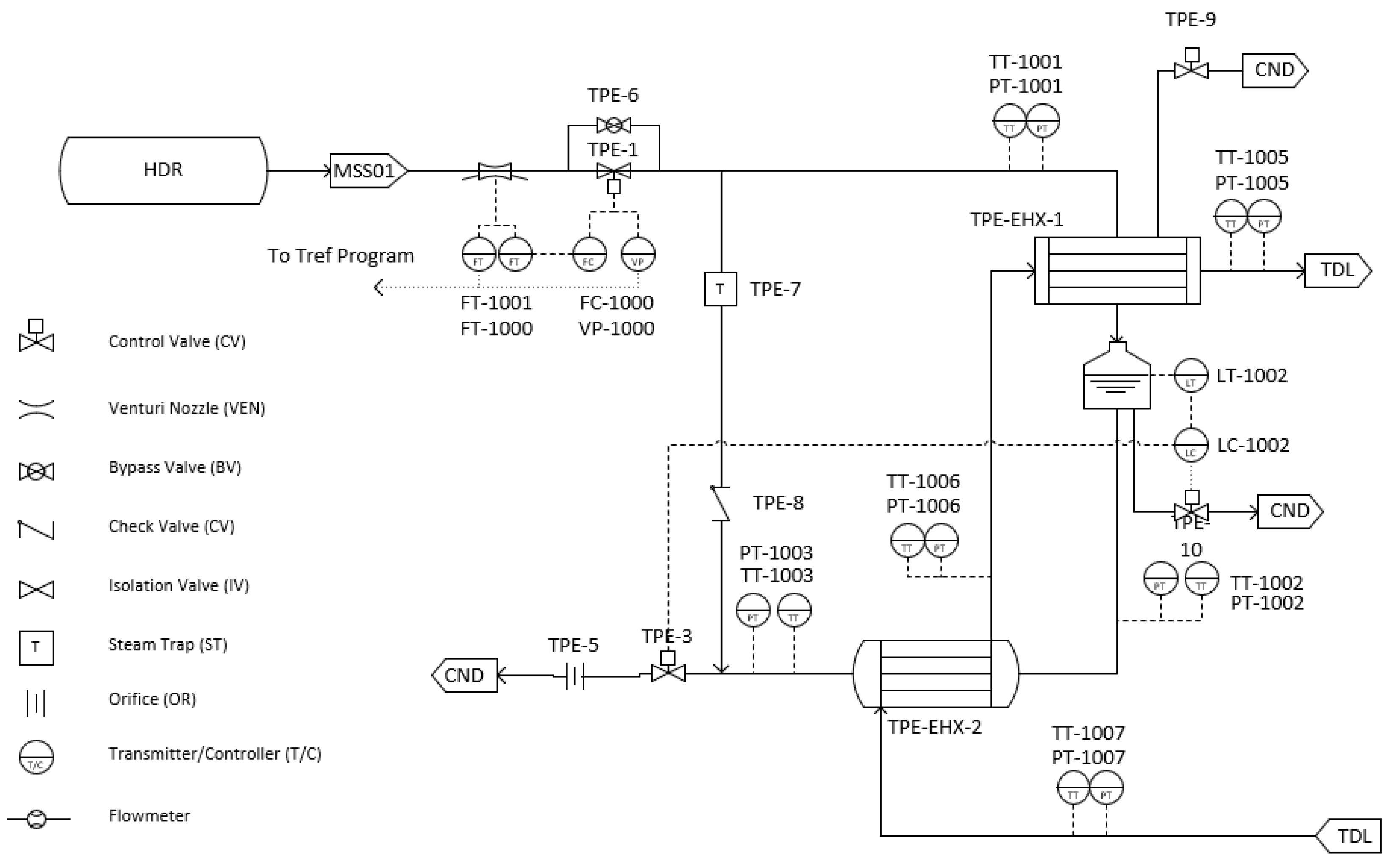
A piping and instrumentation diagram (P&ID) is shown in
Figure 2 for the TPE system running from the main steam header (HDR in
Figure 2) on the secondary loop of the PWR to the main condenser (CND). The steam is extracted from the secondary loop and is condensed and subcooled in the EHX before returning to the condenser. Because steam is extracted from the main steam header where its enthalpy is the highest, the percent of the total steam extracted is equivalent to the thermal power extraction percentage. The TPD loop that transfers the thermal power to the industrial user is labeled TDL in
Figure 2. The total megawatts thermal (MWth) transferred to the TPD loop (TDL) and ultimately to the industrial facility may be higher than implied by the initial extraction percentage, because the industrial facility may use the steam at a lower temperature than the feed water temperature in the steam generator at the NPP.
The P&ID, shown in
Figure 2, contains control and isolation valves for the steam extracted from the main steam header (HDR). There are two separate heat exchangers in the EHX system. The first heat exchanger (TPE-EHX-1) condenses the steam, which is then collected in the hotwell below the heat exchanger. The hotwell level is controlled by a valve at the entrance to the condenser (CND). This level control ensures that only liquid water is present in the second heat exchanger (TPE-EXH-2) and that the liquid remains at a high pressure. This design protects the second heat exchanger from depressurization to possible vacuum pressure.
The TDL is filled with a synthetic oil to carry the heat from the PWR to the industrial facility. There are advantages and disadvantages to using a synthetic oil as the heat delivery medium as opposed to steam. The advantages include liquid-only operation and low operating pressure. This eliminates the need for a backup condenser at the HTSE plant that would otherwise be needed if steam was the heat transfer medium. This condenser would most notably be required in the event of an operational transient at the HTSE plant requiring the plant to go offline. An added advantage of liquid-only operation is the simplification of the heat transfer systems at both the PWR and the HTSE plants, requiring single-phase to two-phase heat transfer as opposed to two-phase to two-phase heat transfer. A lower operating pressure reduces some of the hazards associated with a break in the heat delivery loop. The disadvantage of using oil is the high mass flow rate required to transfer the amount of thermal power extracted. This results in increased capital and operating costs associated with the pipeline and pump system as well as the cost of the fluid inventory to fill the system. Therefore, the oil needs to be liquid at or near atmospheric pressure and beyond the operating temperature of the TPD system.
The TPD system in the modified simulator consists of a pump, 1 km outgoing and 1 km return pipelines, and heat exchangers at both ends. For simplicity, the heat exchangers at the industrial facility are represented by a mass sink that absorbs the oil at the end of the TPD loop and also a mass source that injects the same oil mass back into the TPD loop at the same location but at a lower temperature. Therefore, the only element missing from
Figure 2 for accurate representation of the TPD loop in the modified simulator is the pump. A custom oil based on the properties of Therminol 66
® (Eastman Chemical Company, Kingsport, TX, USA) was included as the operating fluid in the TPD system of the modified simulator. Therminol 66
® has a normal boiling point of 359 °C (678 °F), making it a good candidate for this system given the operating temperatures shown in
Table 1 and the desired oil characteristics for the system [
22].
The heat exchangers were designed to achieve the operating parameters specified in
Table 1. The process was driven by the temperature of the heat sink at the industrial facility. For this application, it was assumed that the industrial process requires feed water at a vaporization temperature of 160.0 °C (320.0 °F), which is consistent with high-temperature electrolysis requirements. Each heat exchanger set was designed to have a minimum approach temperature of 16.7 °C (30.0 °F), such that the temperature of the oil that is re-injected back into the TPD loop was 176.7 °C (350.0 °F). Calculations of thermal losses indicate that the temperature of the oil drops less than 0.05 °C as it travels in each leg of the TPD loop (assuming that the diameter of the TPD loop piping is 36 inches (91.4 cm) and it is surrounded by 2 inches (5.08 cm) of urethane foam). This design indicates that the temperature of the subcooled PWR coolant is 193.3 °C (380.0 °F) as it exits TPE-EXH-2. As specified before, the maximum design steam flow rate in the TPE system was 813.3 kg/s (1793.0 lb/s) or 50% of the maximum steam total flow rate of the main steam header. The design of the TPE and TPD systems in the modified simulator were based on the results of a RELAP5-3D model of the system [
23].
The secondary system of the power plant was represented in the simulator using a two-phase flow mass and energy modeling software called JTopmeret (JADE Build 5.1.1.11274, GSE Systems, Inc., Columbia, MD, USA). This includes all the secondary system units besides the steam generators and the main condenser zones, which were separately modeled in the simulator code [
21]. The modifications required to implement the thermal power extraction system were contained mainly within JTopmeret including the steam extraction line from the main steam header and the heat transfer of the steam to the oil loop. Since the condenser zones were modeled separately, the mass flow and energy flow of the condensate return were manually added to the condenser zone to maintain the balance, otherwise the incomplete balance causes the condenser hotwell level to drop, resulting in a turbine and reactor trip.
3. Proposed Thermal Power Extraction System Operation
The proposed operation is a transition from conventional operation with 100% of thermal power being used to generate electricity to a mixed-mode operation with either 15% or 50% of thermal power being dispatched to an industrial user. It was intended that this transition take place over a time period of approximately 30 min. The percentage of thermal power extraction was not measured by the MWth transferred through the TPE and TPD systems but the mass flow rate of steam directed to the TPE system compared to the total steam flow rate in the main steam header. The total steam flow rate in the main steam header at full power is approximately 1632.9 kg/s (3600.0 lb/s); thus, the maximum target flow rate of steam in the TPE system is approximately 813.3 kg/s (1793.0 lb/s) (50% of 1632.9 kg/s).
General operating procedures were created for the operator to execute the transition from full electrical power generation to mixed-mode electric power generation with thermal power extraction. The wording and steps of these procedures were based on the operating procedures included in the GPWR simulator and were reviewed by operations personnel for representativeness. A general overview of the process is included herein to provide a background for operations and an understanding of the results in the following
Section 4. Full power operation has a turbine control system set point of 936 MW in the control room. This corresponds to a governor valve position for a net electrical power output close to 936 Megawatt electric (MWe). The actual net electricity at 100% power is approximately 916 MWe. The total thermal power of the reactor is 2900 MWth, yielding an expected net thermal efficiency of 31.6%, according to Equation (1):
where
is the thermal efficiency,
is the net electrical output, and
is the thermal power input to the system.
Prior to transitioning from full electrical power operation, the TPE and TPD systems need to be pressurized and warmed up to decrease the transition time. This requires a small amount of steam to be extracted from the secondary system of the PWR such that the appropriate turbine control system set point is 926 MW, an approximately 1% decrease in turbine load. This same amount of steam extraction is expected to keep the TPE and TPD systems in a hot standby mode even when the industrial user is not using thermal power from the nuclear plant. The advantage of maintaining the TPE and TPD systems in hot standby mode, even when they are not in active use, is that thermal power from the nuclear plant can be dispatched rapidly to the industrial partner upon demand. A disadvantage is that the full electric power dispatch of the NPP is reduced by approximately 1% when the TPE and TPD systems are maintained in hot standby.
The hot standby operating conditions allow an NPP coupled to an industrial facility to transition from full electrical power to TPE in a relatively short amount of time, since both the TPE and TPD systems are pressurized and at temperature. This is ideal if the integrated energy system is intended to maximize profits by transitioning to TPE during off-peak times or intervals of low electricity prices. The following overview of what the procedural transition looks like for the operating system gives insight into potential transients and operator interactions required to perform the transitions between hot standby and TPE operation.
In a PWR, the turbine load demand must be decreased by the operator to decrease the amount of steam supplied to the turbine system. This allows the excess steam to be extracted to the TPE system. If done correctly, this transition can occur while maintaining the reactor and primary system at 100% thermal power and the corresponding operating conditions. The turbine load is decreased by closing the turbine governor valves to throttle the steam flow into the turbine. This causes the pressure in the main steam header to increase. This increase in main steam pressure initiates a temperature feedback loop to the reactor that would cause the reactor power to decrease due to the change in the steam generator thermal balance. This feedback is avoided in this transition by opening the control valve to the TPE system at a similar rate as the governor valves are closed. This prevents the main steam pressure from increasing by providing an alternate path for the steam, and the reactor maintains full thermal power. If the TPE control valve is opened quicker than the governor valves, it throttles the flow to the turbine, and it will result in a condition similar to a steam line leak, depending on the amount of flow provided to the TPE system. This causes the pressure in the main steam header to decrease, causing the temperature feedback to the reactor to increase the reactor power. This is a scenario that can be avoided by the design of the TPE system and the design of its control system.
The transition back to hot standby from the TPE is essentially the reverse operation, where the TPE control valve must be closed at the same rate as the turbine governor valves are reopening. Ideally, this process is automated through the turbine (now steam) control system and balanced appropriately. An additional point of interest in this operation is the Tref–Tavg relationship that defines the balance of primary and secondary system loads. The existing Tref program accounts only for the turbine system as a main steam load in the power plant. In order for the desired transition in power to occur with the reactor at 100% power, the control rods, which are automatically controlled by the Tref program, must not move during the transition. Therefore, the Tref program needs to account for the alternate TPE load by adding a bias to the Tref calculation. A simple bias is inserted in the modified simulator to analyze the mismatch between Tref and Tavg. With the control rods in automatic control, a mismatch of 1.5 °F (0.83 °C) or higher will cause the control rods to move in the modified simulator.
As noted above, this overview does not include heating and pressurizing the TPE and TPD systems or cooling them down and depressurization. Those procedures are performed slowly as a house load over a relatively long time. The flows in the systems in that procedure are small and pose much lower risk to the plant in terms of causing any type of disruption or safety event, and so they are not discussed here.
4. Results
The results of this process are presented in a series of transient plots for several important parameters of NPP operation. These are intended to show that the reactor power was maintained at or slightly below 100% thermal power during the entire transient and that all important systems were maintained at their full power levels. This simulation started by establishing steady state at hot standby, continued with the transition from full electrical power generation to steady-state, mixed-mode operation, and it ended with the transition back to steady-state full electrical power generation. The steps were performed manually during this operation, resulting in multiple steps in the TPE control valve position and was not as smooth as it would be in the case of an automatic control system. Several figures are included that show trends in important PWR parameters for the TPE operation and the reactor operation during these transitions. The axis scale of each parameter is important to note in each of the figures and, in many cases, it was enhanced to show the detail.
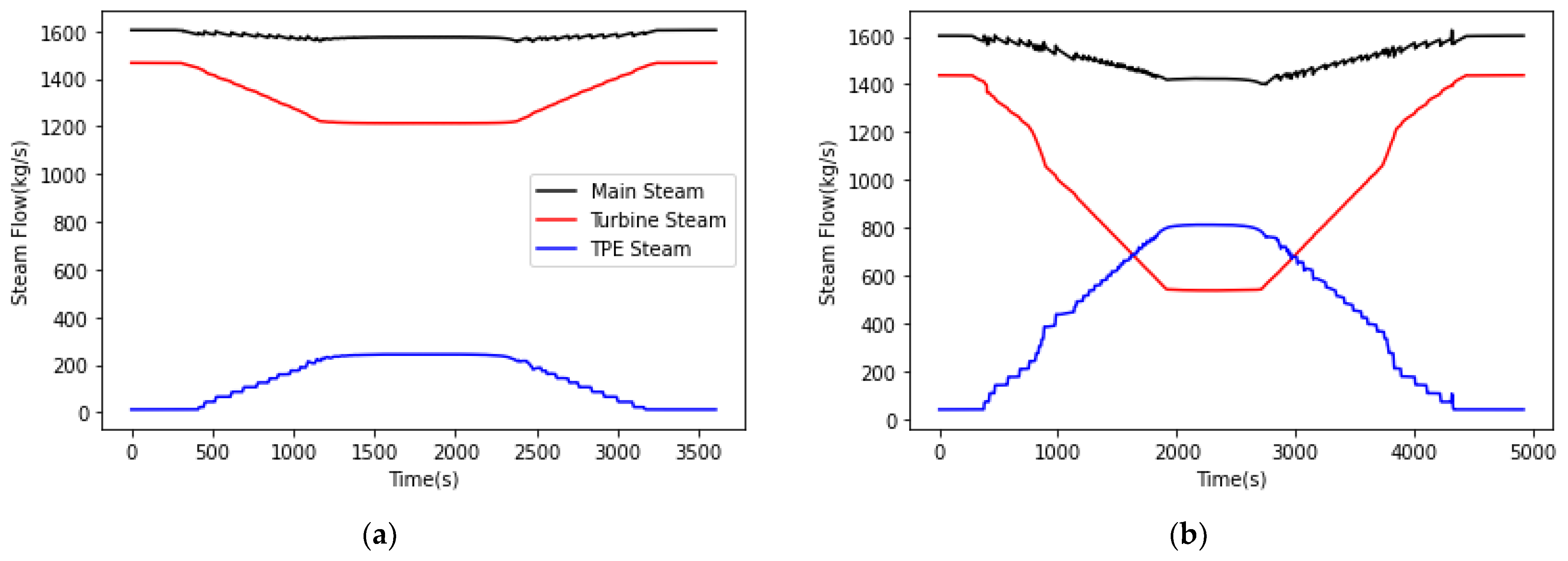
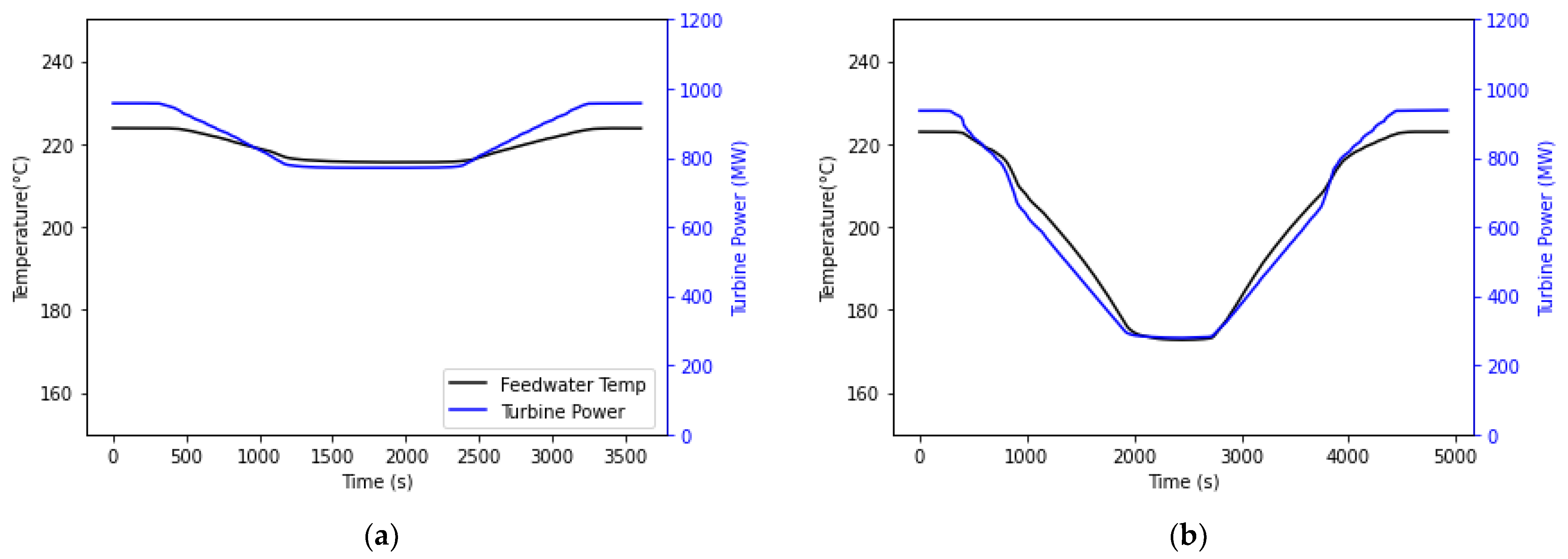
Figure 3 shows the steam flow rates, including those in the main steam header, the TPE system, and the turbine generator (NPP secondary system) for both procedures to start and stop steam flow into the TPE system. Simulations with 15% and 50% thermal power extraction are shown for comparison. Although not intuitive, during the transition from pure electrical power generation to mixed-mode operation, the main steam flow decreases as the TPE valve is opened. The decrease in the main steam flow was matched by a decrease in the steam generator feed water inlet temperature (shown in
Figure 4) such that thermal power balance was maintained in the steam generator. Some heat for the feed water heaters came from steam that was diverted from the turbine generator system; thus, it seems that decreasing the flow of steam in the turbine generator system to provide steam for thermal power extraction also reduced the heat that was provided to the feed water heaters, resulting in the decrease in the feed water inlet temperature as shown in
Figure 4. The steps taken by the operator in manually opening the TPE valve can be seen in the TPE system and main steam flows in
Figure 3, because both of these flows were directly impacted by the TPE valve position. In contrast, the change in the turbine steam flow was relatively smooth.
Figure 4 also shows that the turbine power output exactly mimicked the shape of the turbine steam flow in
Figure 3 as expected.
The most surprising feature of
Figure 4 was the large drop in the turbine power during mixed-mode operations. At 50% thermal power extraction, the power generation of the turbine dropped to 280 MW or approximately 30% of the full power capacity. This result indicates that extracting steam flow from the main steam header and returning the condensate from the TPE heat exchangers substantially derates the performance of the turbine generator system. At 15% thermal power extraction, the power generation of the turbine dropped to 773 MW or approximately 84% of the full power capacity.
The addition of a new main steam load in the system necessitated a change in the calculation of the overall thermal efficiency of the modified system. This can be expressed according to Equation (2):
The added variables to change Equation (1) into Equation (2) were
, which is the efficiency of thermal power dispatch, assumed to be 95% due to the losses in the heat transport system, and
, which is the thermal power transferred to the thermal power dispatch system. The new plant efficiency (
) was the overall thermal efficiency of the system including electrical and thermal power dispatch.
Table 2 shows the overall thermal efficiencies based on the thermal and electrical power outputs at the different amounts of thermal power dispatch of interest to this work. The total thermal power input from the reactor was a constant 2900 MWth in each case.
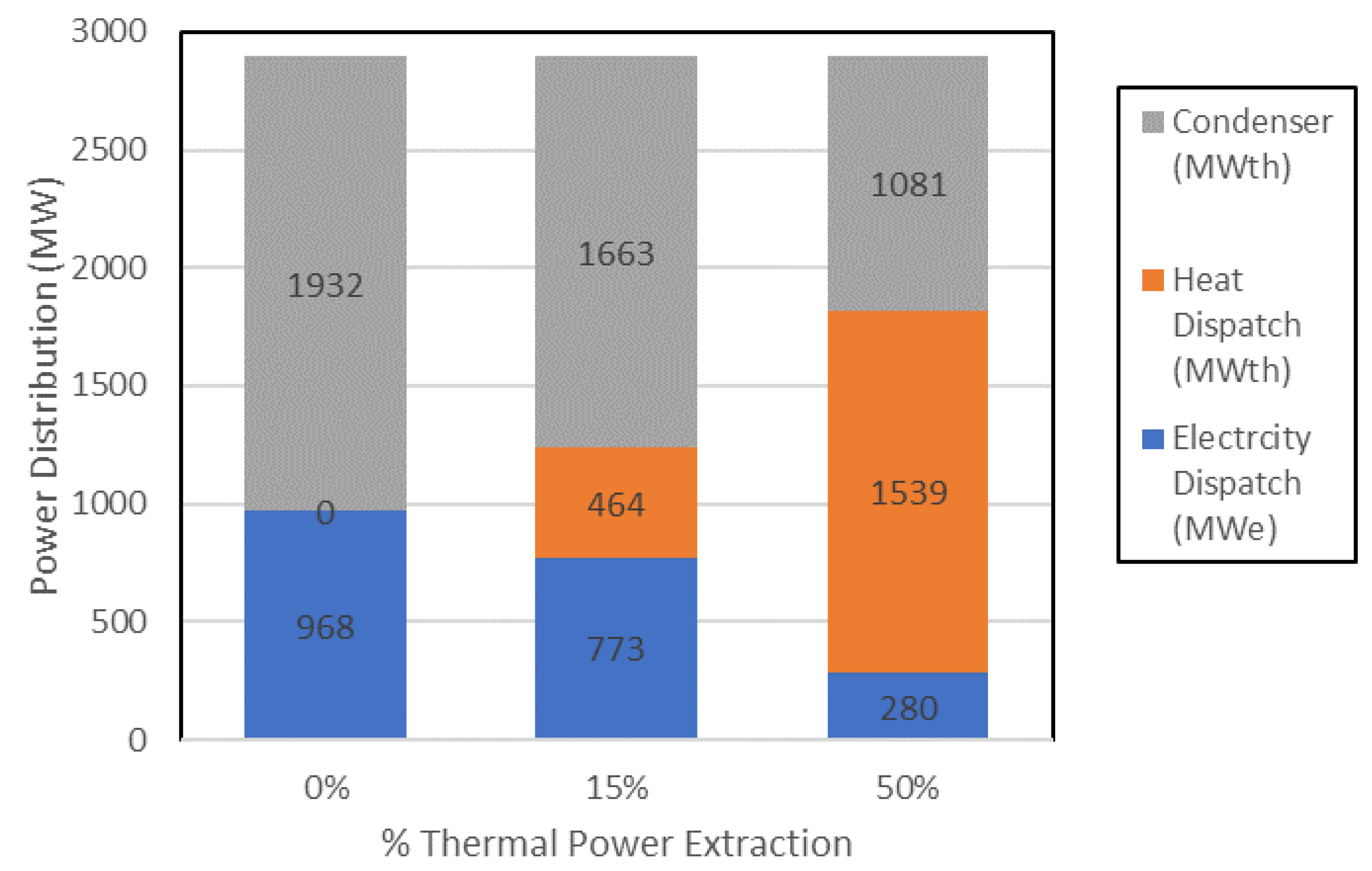
Assuming the steam in the thermal power extraction system can be used with 95% efficiency, the combined power output of the nuclear plant increased during 15% thermal power extraction, resulting in an overall thermal efficiency of 41.9% as shown in
Table 2. Similarly, the combined power output of the nuclear plant during 50% thermal power extraction also increased, yielding an overall thermal efficiency of 60.1%, even though the net electrical output decreased to 30% of the full power output when 50% of the steam was extracted. These approximated results are summarized in
Figure 5, with the overall thermal efficiencies shown in
Table 2.
Figure 5 also shows that for 50% thermal power dispatch, the power dissipated by the condenser decreased from close to 2000 MWth to approximately 1100 MWth, indicating a substantially diminished impact on the environment in terms of heating of the cooling water reservoir. A further point is that by optimizing the return of the condensate from the TPE line to the feed water heaters rather than to the condenser, the loss of main steam flow during thermal power extraction (observed in
Figure 3) could be mitigated and the power factor could be increased above the values indicated in
Figure 3,
Figure 4 and
Figure 5. This hypothesis will be explored in future research.
There are two additional interesting items to note in
Figure 4. First, the response of the steam generator feedwater temperature in
Figure 4 appeared to lag the decrease in the turbine power as steam was diverted to the TPE system. However, when the TPE valve was closed to restore pure electrical power generation, the increase in the turbine power led the change in the steam generator feedwater temperature. A second interesting item was the ratio of the drop of the main steam flow (which corresponded to the drop in feedwater inlet temperature) to the drop in turbine power output.
Figure 5 shows that this ratio was substantially lower for 15% thermal power extraction than it was for 50% thermal power extraction. The relatively lower performance of the turbine generator system at 50% thermal power extraction was likely a consequence of the operating conditions, which were far from its intended operating point where it achieves the design efficiency.
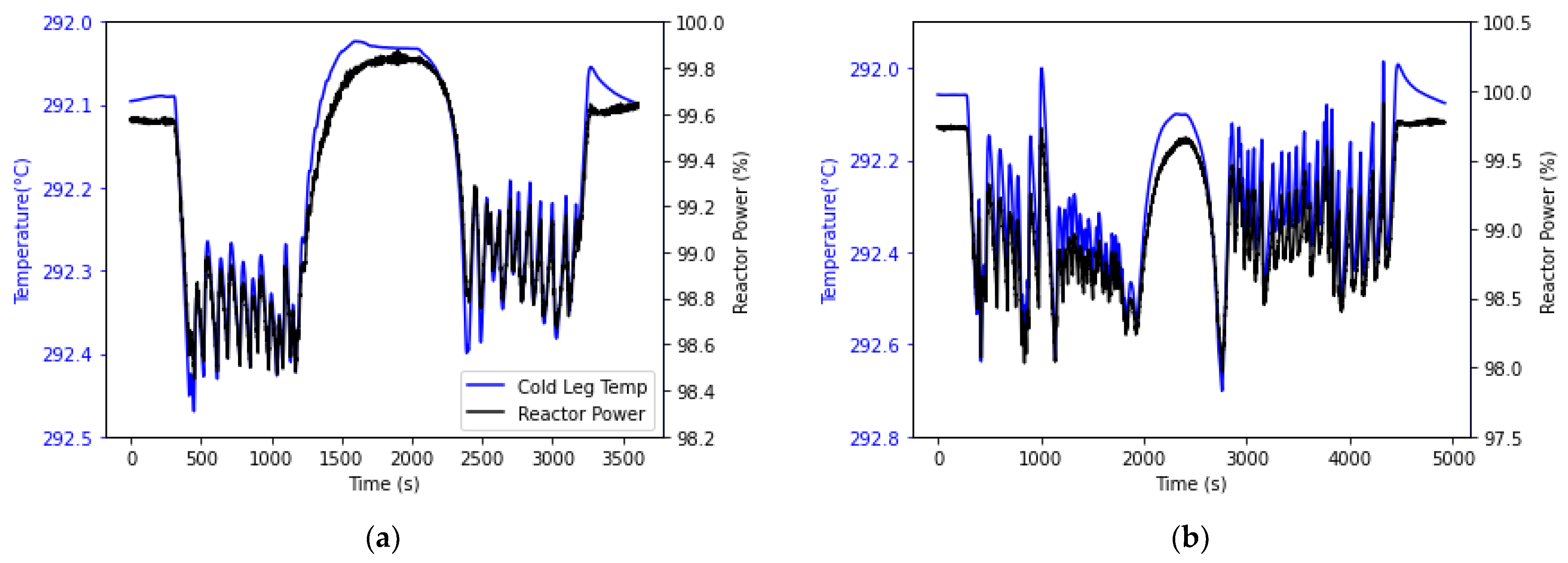
As noted above, a further important consideration is ensuring that the reactor power remained below 100% for the full duration of the transitions between pure electric power generation and mixed-mode operation.
Figure 6 shows that the reactor power oscillated near 99.0% power as intended. As the operator manually opened the TPE valve, the turbine power decreased to the new set point to balance the overall steam flow rate through the steam generator causing the conditions surrounding the steam generator to remain relatively constant. During the transition to 50% thermal power extraction, the reactor power briefly spiked to nearly 100%, indicating that the process still requires refinement to ensure the reactor power does not exceed 100% due to the fact of foreseeable human error. A potential solution is to employ a smaller valve in parallel that can be more finely tuned to stop flow in the TPE line with more finesse.
Figure 6 also shows the cold leg temperature of the RCS during both transitions. The temperature axis was deliberately inverted so that increasing temperature is shown as a downward transition to highlight the tight correspondence between the cold-leg temperature of the RCS and the reactor power. This correspondence is expected because the cold leg temperature has a direct influence on reactor power.
Figure 7 shows the hot leg and average coolant temperatures in the RCS during the transitions. The oscillations in the hot and cold leg temperatures were primarily less than 1 °F (0.55 °C), while the oscillations in the average coolant temperature were less than 0.2 °F (0.1 °C).
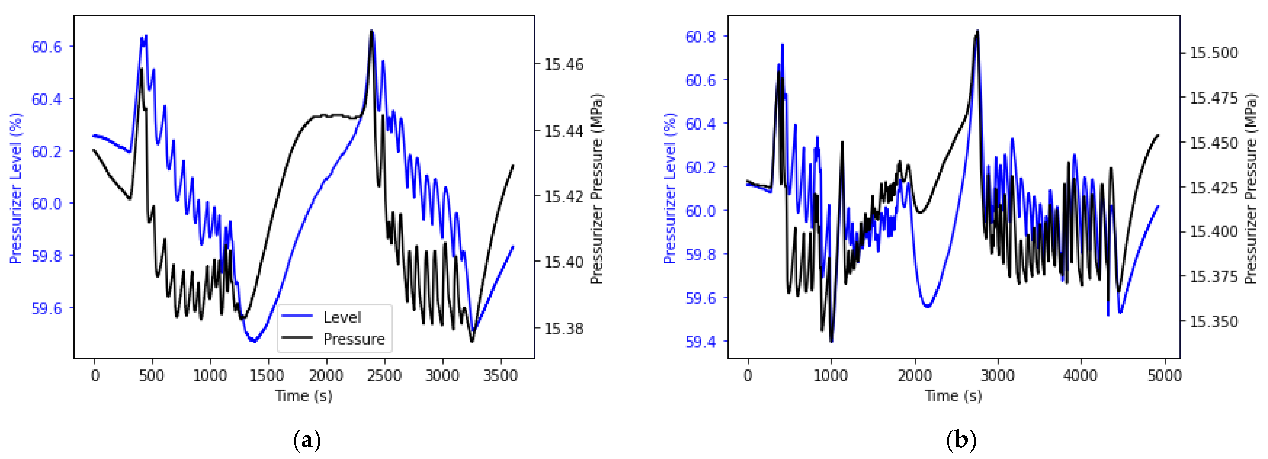
Figure 8 shows the pressurizer pressure and level for each of the changes in operation. As can be seen in these figures, the pressure did not fluctuate much, neither did the level in the pressurizer. The fluctuation that was seen was consistent with the fluctuation in the primary system temperature, which affected the vapor pressure in the pressurizer. The deviations in these values were not significant enough to be a concern during operation, and the level and pressure recovered once the transition finished.
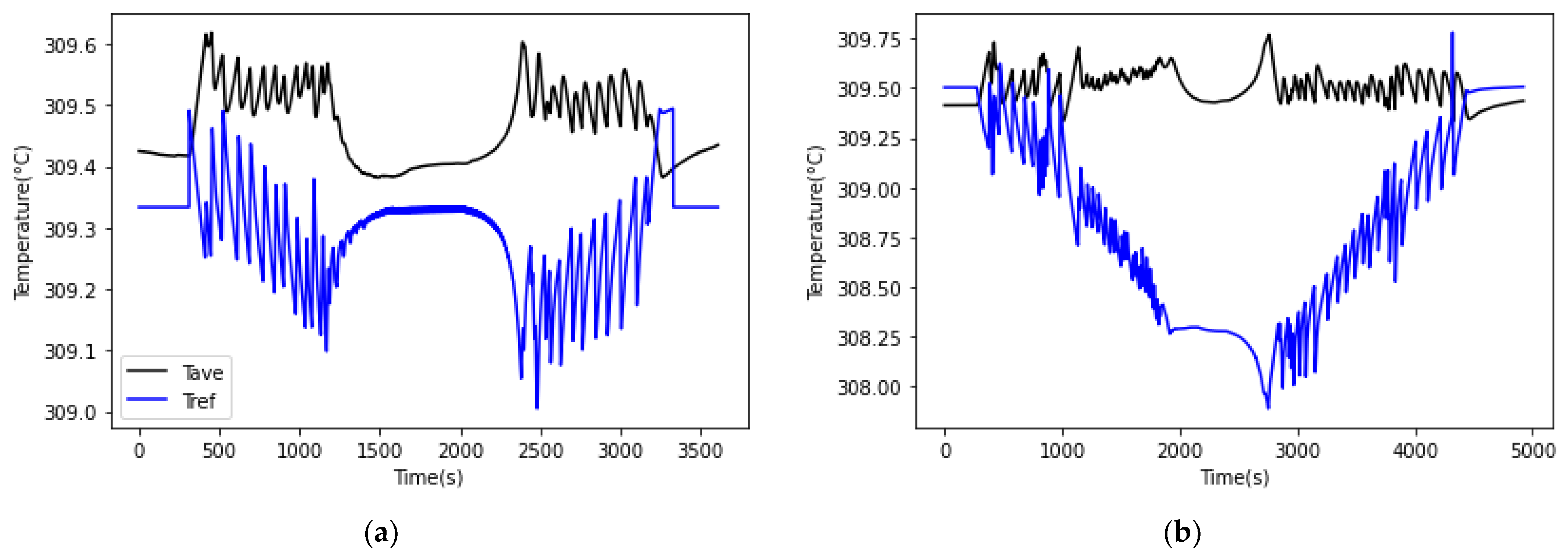
The final items for consideration are Tavg and Tref, which are important for the control rod control system. Tref is a good representation of the power in the secondary loop and is derived from the first stage impulse pressure of the high-pressure turbine. Tavg is a good representation of the power level of the primary loop, as it represents the average primary coolant temperature. As part of the modifications made to the simulator, the Tref program was adjusted to include the TPE steam flow as an additional secondary system load by calculating a fraction of the TPE flow rate as an addition to the Tref calculation based on the impulse pressure. The results for Tavg and the adjusted Tref are shown in
Figure 9. The value of Tref held fairly constant until approximately 3300 s for the simulation with 50% thermal power extraction, and then it began to drop rapidly, indicating that the adjustment to Tref will require additional calibration. Without additional calibration of the Tref program, the control rods would move at approximately 30% power extraction, if left in the automatic control mode. This result indicates that further adjustments are required to the Tref program at higher amounts of thermal power extraction (approximately over 30%), so that this transition can occur in automatic control rod control without triggering any undesired control rod movement.
In a PWR, the Tref to Tavg mismatch is an important control parameter that relates the power levels of the primary and the secondary system for determining control rod position and movement. The Tref program takes the impulse pressure from the high-pressure turbine to calculate a reference temperature for the secondary system power. The inclusion of a TPE system on the steam system adds an additional house load that must also be accounted for when determining the power level of the secondary system. A bias can be used in the Tref program to adjust the reference temperature calculation to include both the load of the turbine, denoted by the impulse pressure, and the load of the TPE system, denoted in this case by a fraction of the steam flow to the TPE system. For low levels of TPE, the current bias calculation functions well as shown in
Figure 9. The Tref value remained relatively constant throughout the first portion of the transition, with some oscillation between the new value and the maximum value. But as the flow of steam in the TPE systems increased, the adjustment to Tref failed, and the mismatch between the temperatures increased. This amount of mismatch would cause movement in the control rods that would affect the reactor power level and many of the important process parameters presented in
Section 4. For the purposes of this study, the control rods were placed in manual mode to prevent any movement and allow for the effectiveness of the Tref bias to be seen, which is not representative of intended real-world operation. A further adjustment is needed in the Tref program so that the control rods can remain motionless in the automatic mode during transitions between pure electric power generation and mixed-mode power dispatch. The results for the transition from TPE back to hot standby provided a similar story as the forward operation and further highlights the need to improve the design.
In addition to the mismatch between Tref and Tavg, there are other concerns that must be studied to fully understand thermal power dispatch from NPPs. This work has focused exclusively on thermal power extraction; however, the thermal and electrical systems are closely coupled so future work should include simulation of the electrical power dispatch to the industrial user as well. For example, greater than 80% of the power required by an HTSE plant is electrical. Production of hydrogen from purely zero-carbon nuclear power could require uncoupling the HTSE plant from the bulk electric grid. The HTSE plant could perform the function of a dispatchable electric and thermal power load for the NPP to allow the NPP to rapidly flex the amount of power that it dispatches to the grid to meet grid needs. However, dynamically dispatching electric power between the HTSE plant and the bulk electric grid may introduce new potential risks that must be mitigated, especially with the additional thermal power demand of the HTSE plant. For example, a failure at the HTSE plant could result in a sudden loss of load with severe consequences to an NPP that is operating at full power while uncoupled from the power grid. Future work will simulate the electrical power dispatch and also the thermal and electrical power coupling with the industrial partner to examine the full range of potential risks in greater detail and to ensure that adequate mitigations are installed.
Another limitation of this work was the exclusive reliance on high-fidelity simulations without experimental validation. Virtual simulations do not capture all physical effects and limitations, such that simulations can predict physically unrealistic operations. For example, during the simulations, valve positions could be read, adjusted, and maintained with any desired level of precision (within the numerical round-off error of the computations). Valves in a physical plant cannot be controlled with such a high level of precision, and it is necessary to verify that the simulation does not employ unrealistic controls via human-in-the-loop testing with operations personnel.
Despite the limitations of the full-scope modified NPP simulations, the results showed that it was possible to transition a PWR from full electrical power generation to 50% TPE in less than one hour with the correct system design. Higher amounts of thermal power extraction appear possible; however, impacts to the NPP and especially to the turbine generator system operations increased nonlinearly as the amount of thermal power extraction increased. The results presented here indicate that the modifications made to a PWR to extract thermal power must be carefully tailored to the desired thermal power extraction and the rate at which the transitions must be made.
An important factor that was not discussed in this work is the additional feedback mechanism introduced by the industrial process plant. In the case of thermal power extraction, an industrial process plant has the potential to affect reactor power through feedback in the steam and oil heat transfer systems. This feedback is not a concern during normal electric power operation, since the large scale of the electric grid is capable of handling power fluctuations, which can essentially be invisible to the nuclear power plant. However, including a direct heat sink, such as an industrial process facility, provides opportunities for undesired feedback to the nuclear reactor from the industrial process. Potential safety impacts, including risks associated with a sudden loss of power at the industrial plant, were investigated in a workshop in which retired licensed reactor operators tested the modified simulator through a range of scenarios using mock procedures [
23]. The operation of the modified system was analyzed by comparing the reactor system and operator responses with and without the thermal power extraction system in operation. Scenarios included a steam generator tube rupture, a main steam line break, and loss of thermal load. The results from these studies showed that the system can influence existing emergency operating procedures [
24]. Prior to implementing this concept in a nuclear power plant, these issues would need to be addressed in a license amendment request (LAR) per 10 CFR 50.90, “Application for amendment of license, construction permit, or early site permit”, or a plant modification per a 10 CFR 50.59, “Changes, tests, and experiments” evaluation. Future work will address the detailed engineering design and process control features that will be needed to implement this system in an existing nuclear power plant including a rigorous 10 CFR 50.59 analysis.


