Article

An Experimental and Computational Investigation of Tailor-Developed Combustion and Air-Handling System Concepts in a Heavy-Duty Gasoline Compression Ignition Engine

1
Aramco Americas: Aramco Research Center Detroit, Novi, MI 48377, USA
2
Cummins, Inc., Columbus, IN 47202, USA
*
Author to whom correspondence should be addressed.
Energies 2022, 15(3), 1087; https://doi.org/10.3390/en15031087
Submission received: 30 December 2021 / Revised: 23 January 2022 / Accepted: 27 January 2022 / Published: 1 February 2022

Abstract

:
This study investigates using tailor-developed combustion and air-handling system concepts to achieve high-efficiency, clean gasoline compression ignition (GCI) combustion, aimed at addressing a future heavy-duty ultralow NOx standard of 0.027 g/kWh at the vehicle tailpipe and the tightening CO2 limits around the world by combining GCI with a cost-effective engine aftertreatment system. The development activities were conducted based on a 15 L heavy-duty diesel engine. By taking an analysis-led design approach, a first-generation (Gen1) GCI engine concept was developed and tested, encompassing tailor-designed piston bowl geometry, fuel spray pattern, and swirl motion paired with a customized, fixed-geometry, two-stage turbocharging system and a high-pressure EGR loop with two-stage cooling. Across four key steady-state operating points, the Gen1 GCI concept demonstrated 85–95% lower smoke and 2–3% better diesel-equivalent gross indicated fuel consumption compared to the diesel baseline at 1 g/kWh engine-out NOx. By upgrading to a Gen2 air-handling concept that was composed of a prototype, single-stage, variable-geometry turbocharger and a less restrictive EGR loop, 1D system-level analysis predicted that the pumping mean effective pressure was reduced by 43–54% and the diesel-equivalent brake-specific fuel consumption was improved by 2–4%, thereby demonstrating the performance enhancement potential of refining the air-handling system.

1. Introduction

The commercial transport sector is facing rising regulatory demand for near-zero criteria pollutants and significantly lower CO2 emissions. In North America, the California Air Resources Board (CARB) aims to reduce heavy-duty commercial vehicle tailpipe NOx emissions by 90% to 0.027 g/kWh [1,2]. Meanwhile, the CO2 emissions standards are tightening around the world [3]. Addressing these challenges is likely to incur increased costs and complexity for commercial engines and aftertreatment systems. Therefore, combustion strategies that can cost-effectively enhance the NOx/soot tradeoff while achieving diesel-like or better fuel consumption will be of interest to engine manufacturers. For this purpose, gasoline compression ignition (GCI) has the potential to produce low-engine-out criteria pollutants and high fuel efficiency by harnessing gasoline’s low oxidation reactivity and unique spray behavior to enhance in-cylinder fuel–air mixing.
GCI can be categorized into several combustion modes based on the extent of fuel stratification [4]. Under homogeneous charge compression ignition (HCCI), the cylinder charge is either fully premixed or lightly stratified. Relying heavily on gasoline’s low-to-intermediate temperature oxidation chemistry, the autoignition event occurs simultaneously across the engine cylinder, triggering a fast heat release process [5]. Consequently, when operated under ultra-lean and diluted conditions, HCCI demonstrated diesel-like fuel efficiency with ultra-low NOx and soot emissions at part loads [6,7]. However, since the combustion process is driven primarily by chemical kinetics, it has proven to be challenging to achieve robust combustion control across a wide engine operating range and during transient operation, thereby hindering its adoption for practical applications [6,7,8].
To gain improved control over the combustion process, a gasoline partially premixed compression ignition (PPCI) concept has been developed and investigated by Kalghatgi and coworkers [9,10] to strengthen the in-cylinder fuel stratification by tailoring the fuel injection strategy while utilizing gasoline’s low autoignition reactivity to ensure the fuel–air mixture is sufficiently premixed before the start of combustion. By implementing this strategy, high-efficiency and clean gasoline PPCI operation has been demonstrated at high loads [11,12]. In a heavy-duty single-cylinder engine, Manente et al. [11] demonstrated ~52% gross indicated thermal efficiency (ITEg) at 26 bar gross indicated mean effective pressure (IMEPg) when relaxing the maximum pressure rise rate (MPRR) to >15 bar/CAD and using idealized thermal boundary conditions including >3.5 bar absolute intake pressure, 303 K intake temperature, and ~50% EGR. While this setup showed performance enhancement potential compared to HCCI, the flow (air and EGR) and charge cooling requirements for high-load PPCI operation are difficult to meet for a practical air-handling system on a multicylinder engine. Furthermore, it remains difficult to balance between controlling the MPRR and attaining high fuel efficiency with low soot emissions. In addition, gasoline’s low reactivity combined with high EGR dilution levels brings challenges for low-load and cold operation in terms of combustion stability and HC and CO emissions, thereby demanding appropriate aiding strategies (e.g., exhaust rebreathing, negative valve overlap, and spark assistance) [13,14,15] and potentially new oxidation catalyst formulations.
Recognizing these barriers, mixing-controlled (diffusion) GCI has gained increasing interest as a pragmatic approach by employing heavy in-cylinder fuel stratification and relaxing the charge flow requirements [16,17,18,19,20]. Recently, a two-stage combustion process that combines PPCI and diffusion combustion (PPCI–diffusion) has shown encouraging results to further improve high-load GCI performance [21,22,23,24,25]. The air-handling boundary conditions are designed purposely to be between those for PPCI and MCCI combustion (e.g., 30–40% EGR and 1.3–1.5 lambda [24,26]). The two-stage combustion process is attained by using a split fuel injection strategy with two injection events taking place in the compression stroke. The first-stage PPCI combustion serves as an effective means to tailor the in-cylinder thermal environment and thus to influence the second-stage ignition delay, while a carefully designed second-stage diffusion combustion process provides robust control over the combustion phasing, combustion duration, and combustion noise. Utilizing this strategy, Sellnau et al. [22] demonstrated a peak brake thermal efficiency (BTE) of 43% and a broad engine operating range with ≥40% BTE in a 2.2 L GCI engine. Subsequently, Zhang and Sellnau [24] showed that optimizing the fuel injection strategy and the injector spray pattern together for PPCI–diffusion combustion had the potential to markedly reduce NOx and soot emissions and improve fuel efficiency compared to a modern 2.0 L diesel engine at 23 bar IMEP.
To reach GCI’s full performance potential, it is crucial to optimize the combustion and air-handling system specifications together. The combustion system design requires careful balancing between enhancing geometry-guided fuel–air mixing and reducing in-cylinder heat transfer losses [27,28,29,30,31,32,33], while the air-handling system needs to be practically viable and meet the charge flow requirements with high gas exchange efficiency [34,35]. The current study aims to develop GCI as an enabling technology to meet CARB’s 0.027 g/kWh tailpipe NOx standard, using a cost-effective aftertreatment system while demonstrating reduced CO2 emissions compared to diesel. Building on previous experimental and analysis-led design results [26,35,36,37], the performance of a first generation (Gen1) customized GCI engine concept was evaluated. Subsequently, the potential of upgrading to a second generation (Gen2) air-handling concept for enhanced gas exchange performance was investigated.

2. Methodology

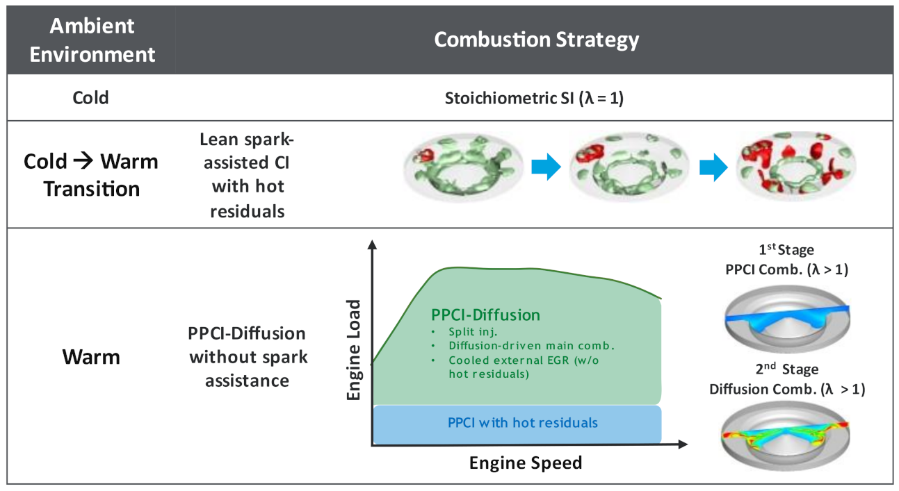
2.1. Combustion Strategy Overview

Figure 1 provides an overview of a full-range GCI combustion strategy that has been conceptualized [24,26]. For engine start at cold ambient temperatures, a stochiometric, spark-initiated flame propagation process is employed. A lean spark assistance strategy is utilized during the cold-to-warm transition. When the engine is fully warm, spark assistance is not used to avoid the complexity and robustness challenges associated with mode transition. For low-load operation, a PPCI combustion strategy aided by inducting hot residuals into engine cylinder through exhaust rebreathing is adopted. At mid to high loads, the combustion strategy migrates to a two-stage PPCI–diffusion combustion process enabled by implementing a split fuel injection strategy combined with adequate boost and cooled external EGR.

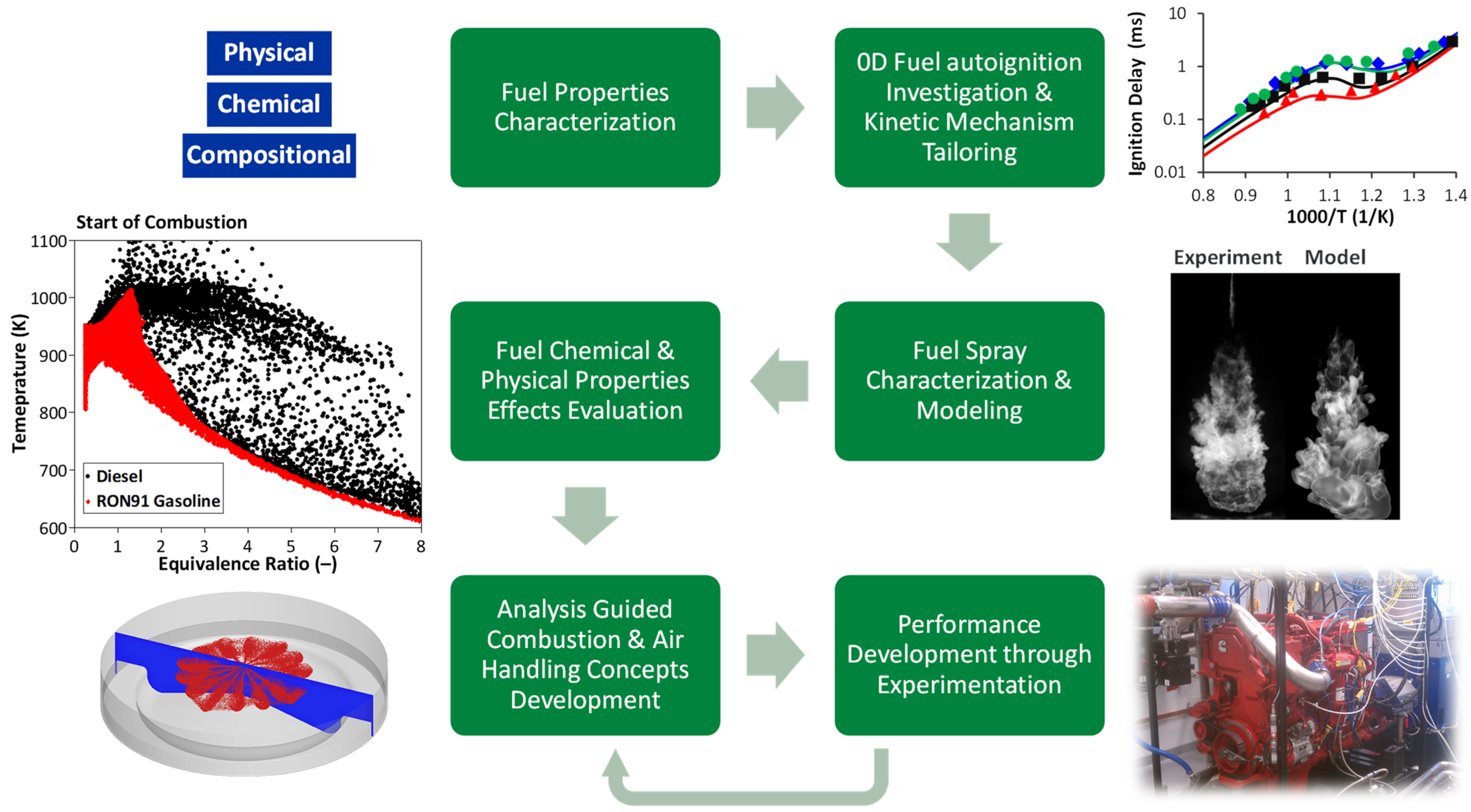
2.2. Analysis-Led Design Approach

An analysis-led design approach was undertaken to develop customized GCI combustion and air-handling system concepts (Figure 2). First, fuel physical, chemical, and compositional properties were characterized in detail. Based on these properties, fuel autoignition behavior and spray characteristics were evaluated experimentally under engine-relevant conditions of interest. Utilizing these data, high-fidelity chemical kinetic and spray models were developed. Next, the fuel property effects on spray formation and breakup, fuel–air mixing, combustion, and emissions were thoroughly investigated under targeted combustion modes to understand the attributes that were key to the engine and fuel co-development. Subsequently, a comprehensive analysis-led design process that combined 3D CFD in-cylinder combustion simulations and 1D system-level analysis was employed to generate customized PPCI–diffusion GCI combustion and air-handling system specifications. Finally, these specifications were materialized and evaluated through dynamometer performance testing. The final two steps comprised an iterative process for engine performance optimization.

2.3. Experimental Setup

2.3.1. Engine and Test Cell Instrumentation

The base engine used in the present study was a Cummins ISX15 heavy-duty diesel engine with performance ratings of 2375 Nm at 1000 rpm and 336 kWh at 1800 rpm. It was equipped with a common-rail fuel injection system capable of 2500 bar fuel injection pressure. The key specifications of the base engine can be found in Section 3.1.
An AVL Flowsonix Air unit was used to measure the intake air flow. The fuel flow was metered via a Coriolis-type AVL FuelExact unit. Engine-out gaseous exhaust emissions, encompassing NOx, CO, CO2, O2, and hydrocarbons (HC), were analyzed using a Horiba MEXA 7500DEGR emissions bench. The intake CO2 concentration was also measured to calculate the EGR fraction. Soot emissions were evaluated based on filter smoke number (FSN) measurement via an AVL 415SE Smoke Meter. Kistler 6067C pressure transducers were installed to attain crank angle (CA)-based cylinder pressure data. The subsequent processing and recording of high-speed data were conducted using an AVL IndiModul unit along with an AVL Indicom commercial software package.

2.3.2. Test Fuels

The test fuels included an ultralow sulfur diesel (ULSD) and an ethanol-free (E0) gasoline with 93 RON. The main fuel properties are list in Table 1. An ester-type lubricity additive at 200 ppm concentration was added to the gasoline to protect the production fuel system from extra wear due to gasoline’s low lubricity and viscosity. The dosage rate was selected to generate a wear scar pattern equivalent to that of US market diesel [38]. Furthermore, additional cooling was instrumented on the fuel return to prevent gasoline boiling, thereby preserving consistent fuel-flow measurement accuracy throughout the study.

2.4. Computational Models

2.4.1. One-Dimensional Engine System Model

A commercial 1D engine simulation tool, GT-Power, was used to develop the system model for the Gen1 GCI engine. A detailed description of the sub-models and the governing equations can be found in [39]. Model calibration and validation methodology for GCI can be found in previously published works [35,40]. A brief description of the main modifications made to a prior GCI engine model is provided here.
A customized turbocharging system model was constructed and replaced the stock single-stage VGT in the prior model, including two fixed-geometry turbochargers (low-pressure stage and high-pressure stage), an inter-stage cooler (ISC), and associated volume and pipe size assignments. The volume of the ISC was set to at 30% of the main charge air cooler (CAC). The cooling capacity of ISC and CAC was carefully tuned to deliver 60 °C temperature at the ISC outlet and 40–46 °C temperature at the CAC outlet, respectively, across the engine operating points. In addition, a two-stage EGR cooler was incorporated in the EGR loop along with adjustments made to the volume and the piping of the exhaust manifold and the high-pressure EGR loop to accurately represent the flow and the restrictions in the EGR flow path. The pressure differential across the EGR loop and the effectiveness of the EGR cooler were simulated based on benchmark flow data. In addition, the engine exhaust backpressure was set based on the flow characteristics of the aftertreatment system for the base engine.

2.4.2. Closed-Cycle 3D CFD Model

Closed-cycle, 3D CFD combustion simulations were performed using the commercial software package, Converge. The in-cylinder process simulated during a closed cycle covered the time duration between the intake valve closing (IVC) and the exhaust valve opening (EVO). The primary Converge sub-models are listed in Table 2. A detailed description of these sub-models can be found in [41,42,43]. A base grid size of 1.4 mm was used, while the smallest grid size was 0.35 mm with the use of adaptive mesh refinement (AMR) and fixed nozzle embedding.
The turbulence on the in-cylinder charge was predicted by applying a Reynolds-averaged Navier–Stokes (RANS)-based renormalization group (RNG) k-ε turbulence model [44], while a Lagrangian approach with a “blob” injection method was undertaken to simulate liquid gasoline sprays [45]. The subsequent breakup and collision processes were captured by using the Kelvin–Helmholtz and Rayleigh–Taylor (KH–RT) breakup model [46,47] and the no-time counter (NTC) model [48], respectively. In addition, the Frossling correlation was used to predict the droplet evaporation [49]. The combustion chemistry was resolved using a direct solver, SAGE.
A PRF blend was used as the gas-phase chemical kinetics surrogate to represent the 93 RON gasoline. The reduced chemical kinetic mechanism developed by Liu et al. [50] was employed to simulate the reaction chemistry of the PRF surrogate, consisting of 44 species and 139 reactions. This has been validated against and showed good correlation with experimental data from ignition delay, species concentration, and laminar flame speed measurements. The selection of this reduced PRF mechanism was due to the compact size and the good fidelity demonstrated when modeling GCI combustion [51]. NOx emissions were simulated using a mechanism composed of 4 species and 13 reactions [52], while soot emissions were predicted using the Hiroyasu–NSC (Nagle and Strickland-Constable) approach. Acetylene was used as the inception species in the soot model. The aforementioned PRF kinetic mechanism, NOx chemistry, and soot model were integrated and executed simultaneously in the same computational run.

3. Results and Discussion

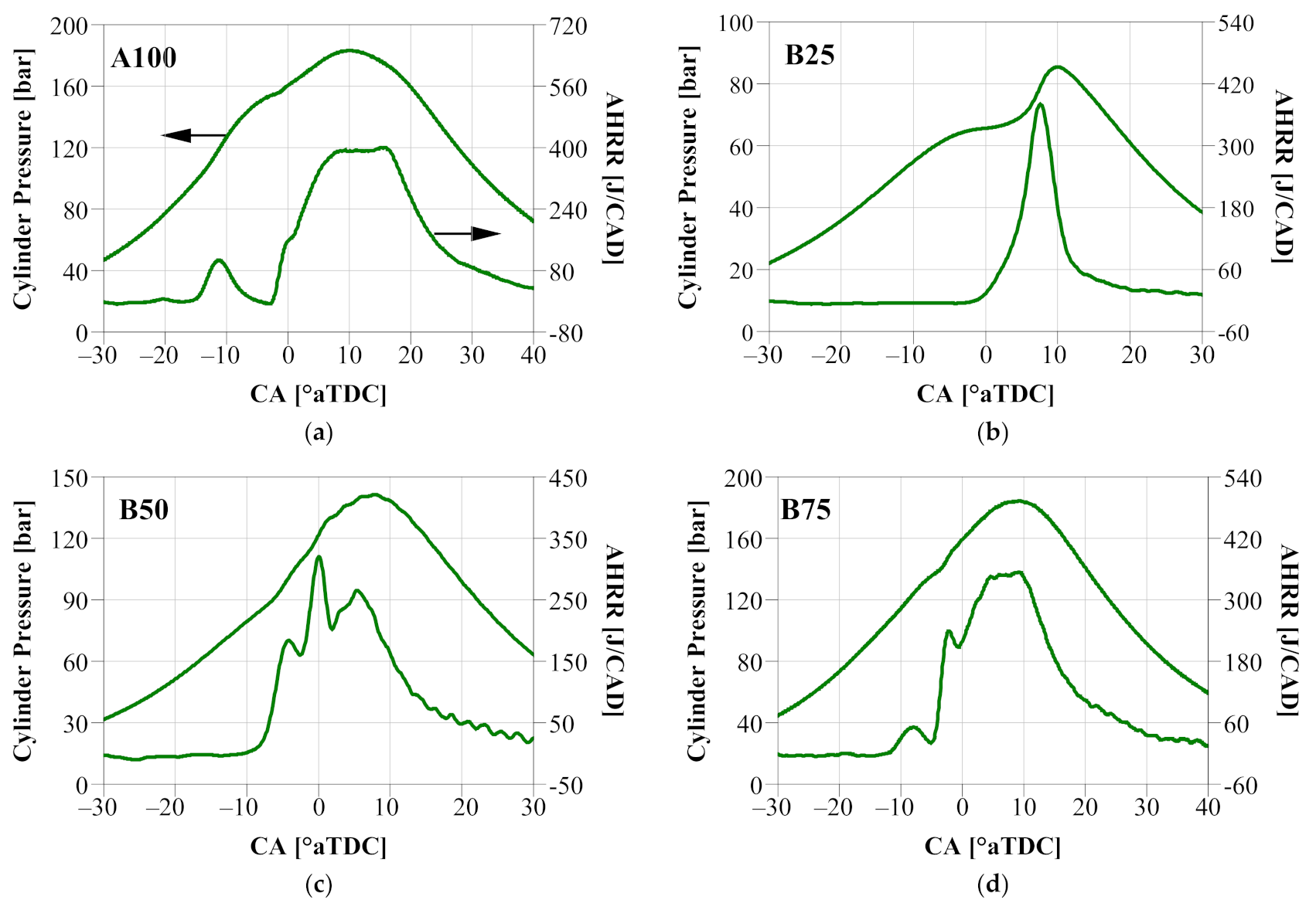
3.1. Gen1 GCI Engine Description

An important first step in developing a high-efficiency, low-NOx GCI engine is to understand the effects of the geometric compression ratio (GCR) and EGR (i.e., engine-out NOx emissions) on soot and fuel efficiency. In Figure 3, a GCR range of 15.7 to 18.9 was investigated for a 93 RON E0 gasoline [36], while the engine-out NOx emissions were varied from 1 to 4 g/kWh.
When developing the Gen1 GCI engine concept, a particular interest was placed on an engine-out NOx range of 1–2 g/kWh. As shown in Figure 3c, a GCR between 15.7 and 17.3 appeared to offer the most favorable smoke/BSFC-D tradeoff. The engine performance was clearly sensitive to the engine-out NOx, suggesting that the air-handling system of the base engine that was developed for 4 g/kWh engine-out NOx may not be a good fit for engine operation under substantially lower NOx conditions. Therefore, it is key to developing combustion and air-handling simultaneously. Based on these experimental observations, a 16.5 GCR was chosen for the Gen1 GCI engine.
The key specifications for the baseline engine and the Gen1 GCI engine are listed in Table 3. Figure 4 shows a layout of the Gen1 engine system. For the Gen1 engine combustion system, a new piston bowl geometry and a customized spray pattern (9-hole and 152° spray inclusion angle) were developed to achieve optimized, geometry-guided fuel–air mixing [26]. The production single-stage VGT was replaced with an off-the-shelf, two-stage, fixed-geometry turbocharging (FGT) system to deliver adequate boost and high EGR flow at the same time. In addition, to increase the charge density, the cooling capacity of the high-pressure EGR loop was appreciably enhanced by implementing a two-stage cooling process. Consequently, the intake manifold temperature was reduced from the baseline level of 75–80 °C down to 60–65 °C for the Gen1 GCI engine. Note that in order to accommodate the customized two-stage EGR cooler, the stock engine exhaust manifold was replaced with an off-the-shelf manifold that was designed to be paired with the two-stage EGR cooler. The connection between the exhaust ports and the new exhaust manifold was custom-made.

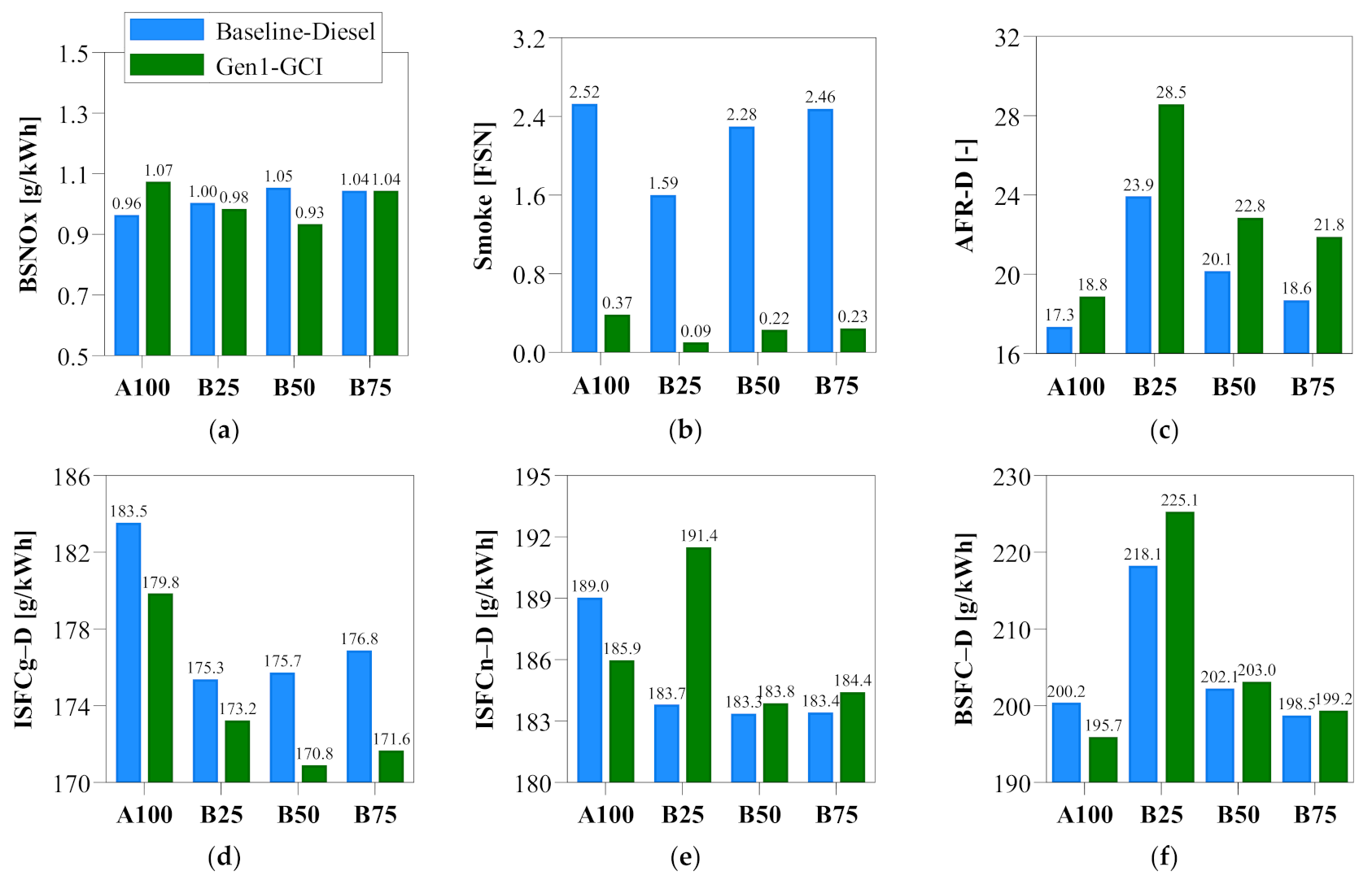
3.2. Gen1 GCI Performance Overview

The engine performance investigation was focused at four key operating points selected from the heavy-duty SET certification cycle, including 1147 rpm/20 bar BMEP (A100), 1375 rpm/5 bar BMEP (B25), 1375 rpm/10 bar BMEP (B50), and 1375 rpm BMEP/15 bar BMEP (B75). Among the four operating points, B50 represents the on-highway cruising operation for the base engine, while B75 is its highest fuel efficiency operating point. The peak torque operation is captured by A100. In addition, B25 is an important low-load operation point where gasoline’s autoignition reactivity impact is pronounced.
Table 4 lists the main engine operating boundary conditions. Building on previous experimental and numerical investigations on GCI combustion strategy development [24,26], a double fuel injection strategy was implemented. The first injection (SOI1) was fixed at −30 °aTDC to achieve favorable spray–bowl interaction for the first-stage PPCI combustion, while the second injection (SOI2) and the fraction of the fuel quantity from the first injection event (Q1) were tuned to attain the best balance between fuel efficiency and the engine mechanical limits. In this study, the peak cylinder pressure (PCP) limit was set at 200 bar. The MPRR was targeted to be below 10 bar /CAD over the entire engine operating range. The EGR and lambda (or diesel-equivalent air–fuel ratio (AFR-D)) were adjusted to achieve high-efficiency, clean operation at 1 g/kWh engine-out NOx.
Figure 5 provides an overview of the Gen1 GCI engine performance results. Compared to the diesel baseline, Gen1 GCI reduced smoke substantially by 85–95%. Moreover, the diesel-equivalent ISFC (ISFCg-D) was improved by 2–3%. In Figure 5c, AFR-D was markedly increased for Gen1 GCI, thereby contributing appreciably to leaner combustion and lower soot emissions. From Figure 5d to Figure 5e, the ISFC benefit from Gen1 GCI became diminished when transitioning from gross- to net-basis, suggesting that the off-the-shelf air-handling system incurred increased pumping losses, although it was capable of meeting the air and EGR flow requirements. Therefore, a strong motivation for developing a Gen2 GCI engine is to improve the gas exchange efficiency.
The global combustion behavior was characterized through in-cylinder pressure trace and apparent heat release rate (AHRR), as seen in Figure 6. Progressing from B25 to A100, GCI combustion gradually evolved from a single-stage PPCI heat release process to a two-stage PPCI–diffusion combustion process where the diffusion combustion became increasingly dominant with load increase. As highlighted in Figure 6c, the first injection event trigged a first-stage, lean PPCI combustion process. Then, after the second injection took place, the second-stage combustion was initiated with a mild, partially premixed combustion phase followed by a pronounced diffusion combustion process. Table 4 shows that migrating from B25 to A100 led to an increased intake manifold pressure and a reduced EGR fraction. Consequently, the thermal reactivity of the cylinder charge progressively increased due to higher cylinder pressure (Figure 6) and lower EGR dilution, thereby resulting in shortened second-stage ignition delay and more pronounced diffusion combustion. Due to enhanced charge thermal reactivity, Q1 also had to be reduced with the load increase to avoid excessive MPRR and PCP. A detailed comparison of the in-cylinder global combustion behavior and fuel–air mixing characteristics between the diesel baseline and the Gen1 GCI concept is provided in Section 3.4.

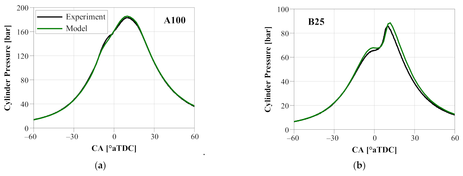
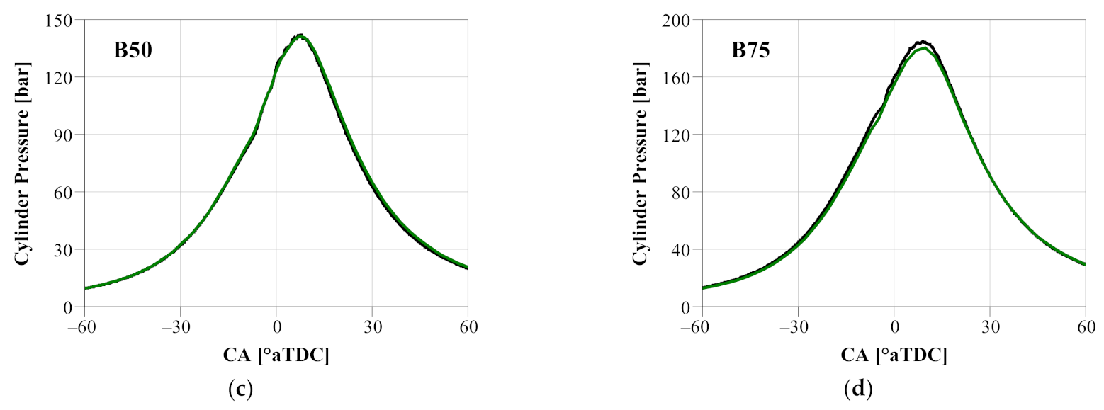
3.3. Validation of 1D and 3D Computational Models

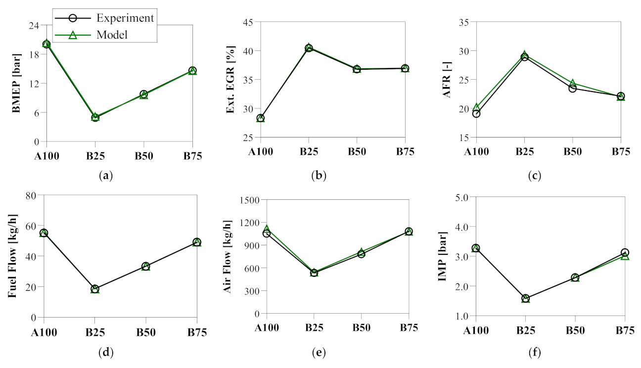
3.3.1. One-Dimensional Engine System Model Validation

To capture in-cylinder combustion, experimental heat release rate profiles and injection rate shapes were imported into the 1D model. The “Woschni-GT” heat transfer model was used to simulate the in-cylinder heat transfer process with the heat transfer multiplier carefully tuned to reproduce the in-cylinder pressure traces. A ±3% error band was enforced when evaluating the in-cylinder pressure matching between the 1D model predictions and the experimental data. As seen in Figure 7, the 1D model was able to adequately predict the in-cylinder pressure traces across the four operating points.
Figure 8 shows that the key Gen1 GCI engine operating boundary conditions, including the EGR fraction, AFR, air flow, fuel flow, and pressure and temperature at both intake and exhaust manifold were well reproduced by the 1D model. Thus, sufficient confidence was acquired to utilize the 1D Gen1 GCI engine model to gain insight into the air-handling performance and identify the areas for further improvement. The high-pressure turbocharger was observed to be responsible for 60–70% of the work from the two-stage boosting system. In Figure 8, the pressure differential across the engine was in the range of 25 to 70 kPa, corroborating the high pumping losses discussed in Section 3.2. Therefore, it is imperative to improve the turbocharging system efficiency. In addition, although the customized exhaust manifold and EGR cooler were able to effectively enhance the EGR gas cooling capacity, they incurred increased flow restrictions and need to be optimized when developing a Gen2 GCI engine.

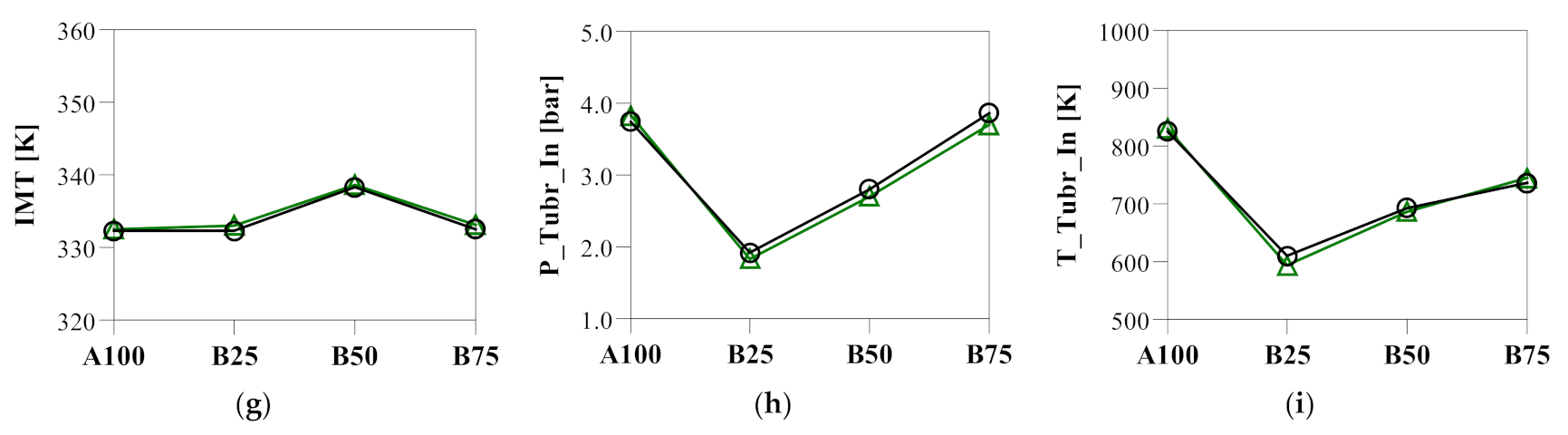
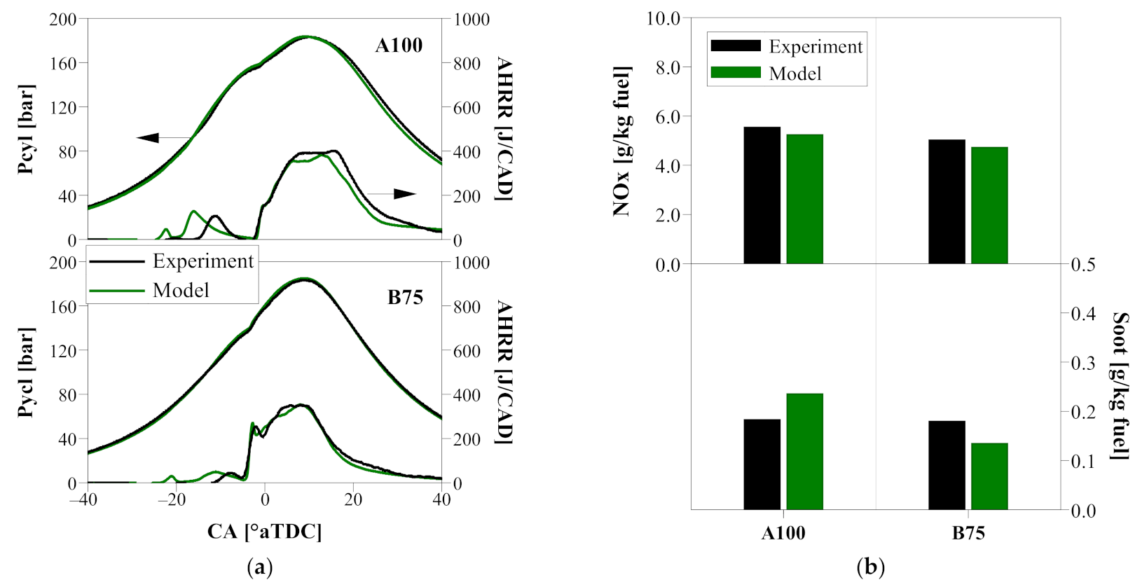
3.3.2. Three-Dimensional CFD Combustion Model Validation

The three-dimensional CFD model validation was conducted at A100 and B75. The thermal boundary conditions at IVC were produced from the abovementioned 1D engine system model. The model constants for the gasoline spray were determined based on the spray characterization data produced in a constant-volume combustion vessel [53]. The soot model rate coefficients were kept consistent at both model validation points.
Figure 9a shows that the AHRR and the cylinder pressure trace were simulated by the model reasonably well. The model was seen to produce an earlier and stronger occurrence of the first-stage combustion, suggesting that there is a need to improve the low-temperature oxidation chemistry of the PRF kinetic mechanism, as reported in a previous study [51]. In addition, since gasoline consists of a variety of hydrocarbon classes, replacing the current binary PRF surrogate with a multicomponent surrogate may offer the potential to further improve the model fidelity. With respect to NOx and soot emissions, the modeling results and the experimental data were seen to be in good agreement, as shown Figure 9b.

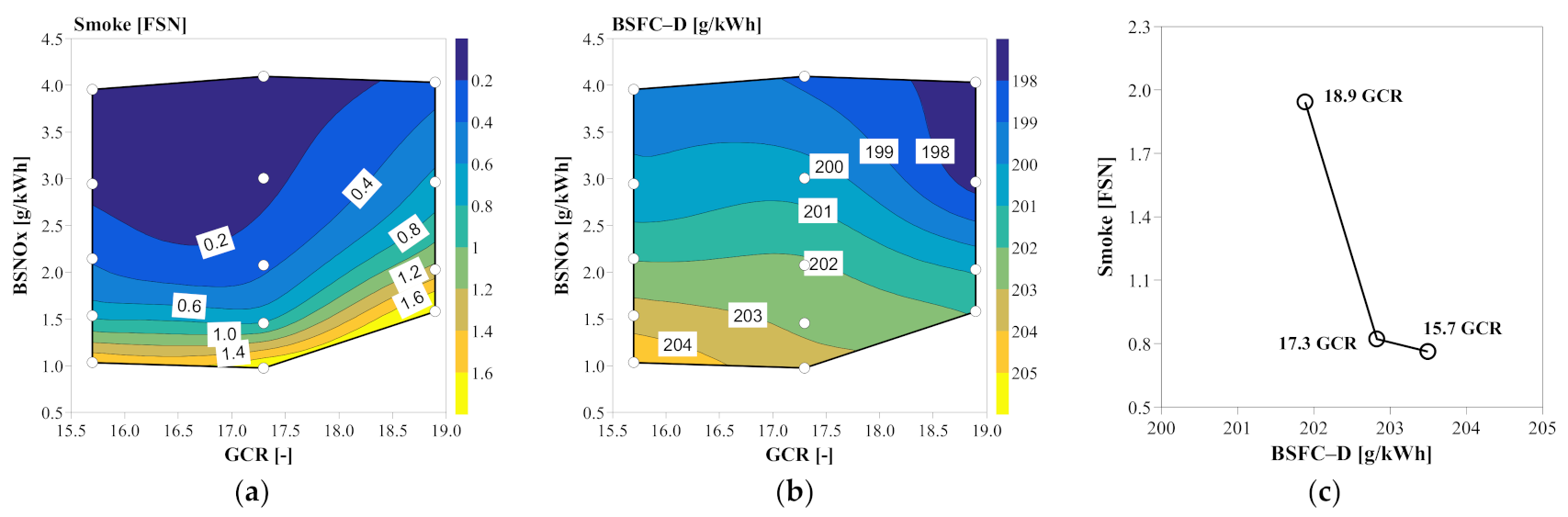
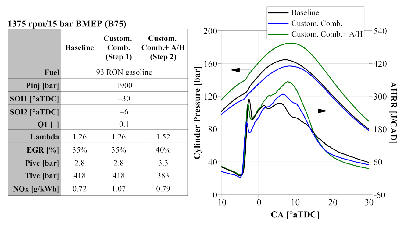
3.4. Gen1 GCI Performance Evaluation at B75

Since B75 represents the highest fuel efficiency operating point for the base engine, a detailed performance evaluation was first conducted at this test point. Specifically, 3D CFD combustion analysis was conducted to separate the effects between the redesigned combustion system and the customized air-handling concept.
In Figure 10, the PPCI–diffusion combustion process was characterized through the cross-sectional equivalence ratio (Phi) and temperature contours. As seen in Figure 10, the first fuel injection targeted the bowl rim, aimed at utilizing the air in the upper portion of the bowl and the squish. It initiated a first-stage PPCI combustion process and progressively started to build up an appropriate thermal environment for the main combustion event. Subsequently, the second fuel injection was designed to utilize the lip in the piston bowl to promote geometry-guided fuel–air mixing across the combustion chamber, thereby producing a fast, clean, and fuel-efficient diffusion combustion process. The split injection strategy employed can be conveniently calibrated, encompassing SOI1, SOI2, Q1, and Pinj. The PPCI–diffusion combustion process was optimized by collectively implementing a tailored split injection strategy paired with a customized combustion system concept consisting of piston bowl geometry, injector spray pattern, and swirl motion. As reported previously, the customized piston bowl design was narrower and deeper than the baseline piston bowl geometry by harnessing gasoline’s shorter spray liquid length [26,51].
A step-wise approach was undertaken to identify the individual effects from the Gen1 combustion system and air-handling concept, respectively (Figure 11). In the first step (Step 1), only a combustion system redesign was introduced. Then, building on Step 1, enhanced thermal boundary conditions were implemented in the second step (Step 2), including a simultaneous delivery of high air and EGR flow along with improved charge cooling. Figure 11 shows that the diffusion combustion process became increasingly accelerated from the baseline configuration to Step 2, thereby progressively increasing the effective expansion ratio and enhancing the late-stage air utilization.
The in-cylinder air utilization was evaluated by comparing the mass fraction of the in-cylinder fuel–air mixture at equivalence ratio bands of Phi > 1 and Phi > 2. It should be noted that reducing the presence of locally fuel-rich regions represents improved air utilization, thereby leading to faster diffusion combustion and enhanced soot oxidation. In Figure 12, both Step 1 and Step 2 showed better air utilization than the baseline at CA50 and CA75. Moreover, it is important to note that the impact from Step 2 was considerably more pronounced, highlighting the critical role of the air-handling performance in the low-NOx GCI technology development process.

3.5. Gen1 Engine Performance Evaluation at B50

Following B75, B50 is another crucial engine operating point that was investigated in detail as it mimics the on-highway cruising operation for the base diesel engine. In this section, a performance comparison between diesel and gasoline was first conducted; then, the impact of the fuel injection strategy was investigated.

3.5.1. Diesel vs. Gasoline

The performance comparison was carried out in two steps while keeping the CA50 constant at 5 °aTDC. First, the impact of the Gen1 combustion and air-handling concept on diesel combustion was evaluated (Baseline-Diesel→Gen1-Diesel). Subsequently, a comparison of diesel vs. gasoline was provided using the customized Gen1 engine system (Gen1-Diesel→Gen1-GCI).
The global combustion behavior and the key performance results are captured in Figure 13 and Figure 14, respectively. In Figure 13 and Figure 14c, it is clear that the customized Gen1 combustion and air-handling concept promoted a faster and leaner diffusion combustion process for diesel, thereby shortening the combustion duration (CA10–90) from 36.2 to 31 CAD (Figure 14f), reducing the smoke by 69% (Figure 14b), and improving ISFCg-D by 1.8% (Figure 14d). Collectively, these results demonstrated that the Gen1 engine combustion and air-handling concept can be well harnessed to improve the emissions and fuel efficiency for diesel diffusion combustion.
In Figure 14e, it is worth noting that although the ISFCg-D for diesel combustion was enhanced by using the Gen1 concept, the trend was reversed for ISFCn-D. Similar to the observation in Section 3.2, the reversion in trend confirmed that the off-the-shelf air-handling system (turbocharging and EGR loop) incurred high pumping losses. Therefore, there is a clear need to improve the gas exchange efficiency.
When applying the 93 RON gasoline on the Gen1 engine, the smoke reduction was extended to 90% (Figure 14b), while the ISFCg-D benefit was enhanced to 2.8% (Figure 14d) through the custom-designed PPCI–diffusion combustion process. As expected, combining the RON93 gasoline and the Gen1 engine produced the best performance results. Figure 13 shows that by applying a double fuel injection strategy, GCI produced the strongest partially-premixed combustion along with a fast late-stage diffusion combustion process, thereby leading to the shortest CA10–90 and the lowest ISFCg-D.

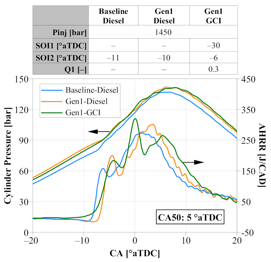
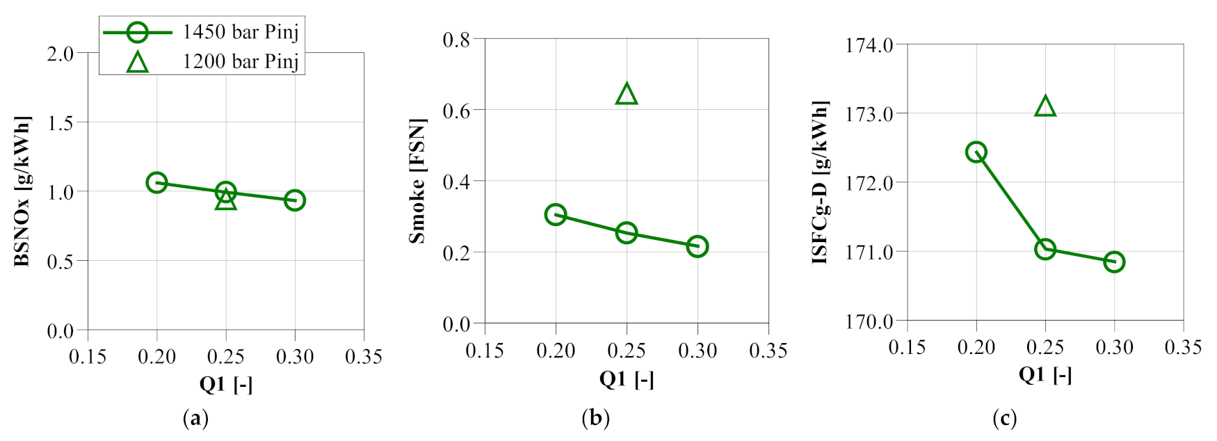
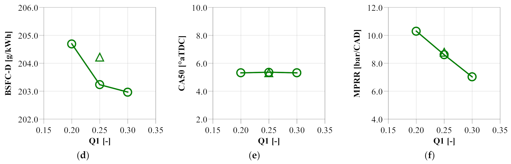
3.5.2. Impact of Fuel Injection Strategy

When investigating the fuel injection strategy effects, SOI1 was set at −30 °aTDC based on the aforementioned combustion system design for spray targeting. The SOI2 was varied to maintain CA50 at ~5 °aTDC for the best fuel efficiency. Thus, the fuel injection strategy investigation was focused on Q1 and Pinj. Figure 15 provides an overview of the performance results, capturing the effects of varying Q1 from 0.2 to 0.3 at 1450 Pinj and adjusting Pinj from 1200 to 1400 bar at 0.25 Q1. The global combustion behavior was characterized through cylinder pressure and AHRR, as shown in Figure 16.
Figure 16a shows that increasing Q1 produced a more pronounced first-stage partially premixed combustion and a reduced peak AHRR, thereby leading to a lower MPRR, fewer in-cylinder heat transfer losses, and better overall in-cylinder air utilization. Therefore, both smoke and fuel efficiency were improved (Figure 15b,c). However, as noted in the smoke and ISFCg-D trends, the improvement started to slow down as Q1 increased from 0.25 to 0.3. This can be attributed to a competing effect between the reduced effective expansion ratio caused by the lengthened combustion duration (Figure 16a) and the abovementioned reduction in heat transfer losses due to the reduced peak AHRR.
In terms of the impact of the Pinj, Figure 15 shows that increasing the Pinj from 1200 to 1450 bar led to a 61% reduction in smoke and 1.2% better ISFCg-D. The favorable performance was due to enhanced air-entrainment into the fuel plumes and a wider spread of fuel sprays, thereby improving the fuel–air mixing and promoting a stronger and faster diffusion combustion process (Figure 16b).

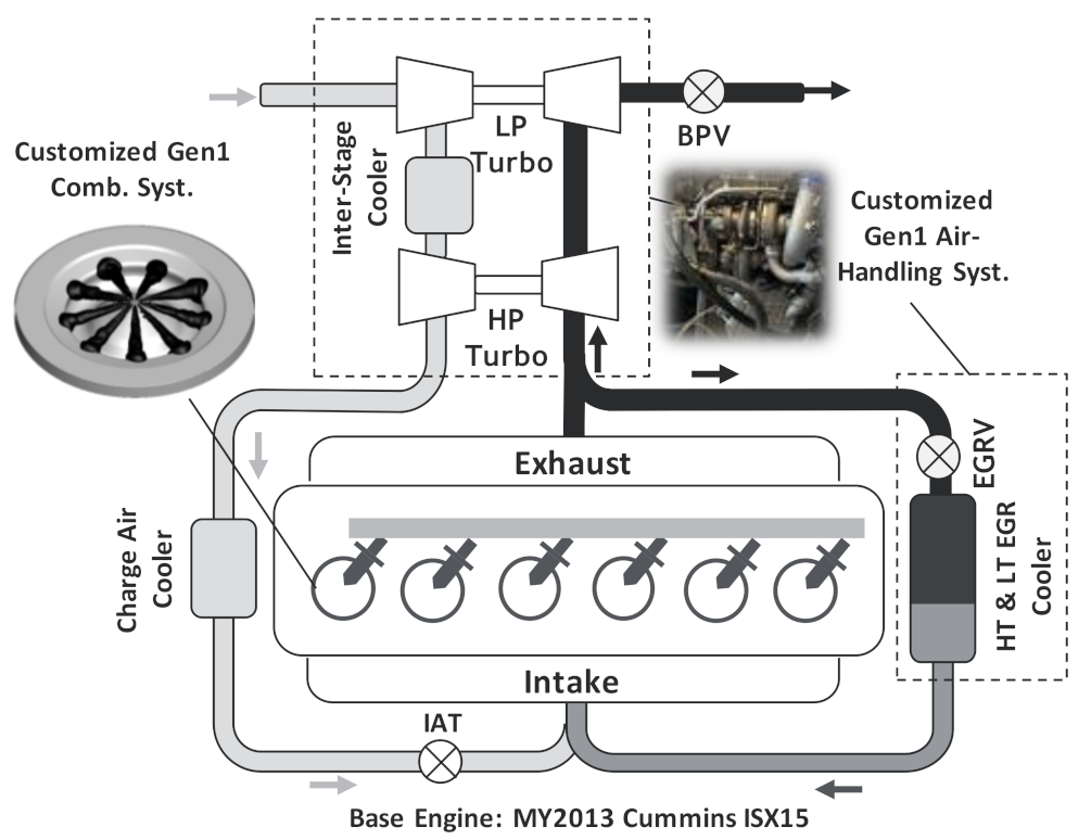
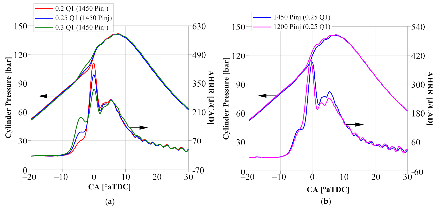
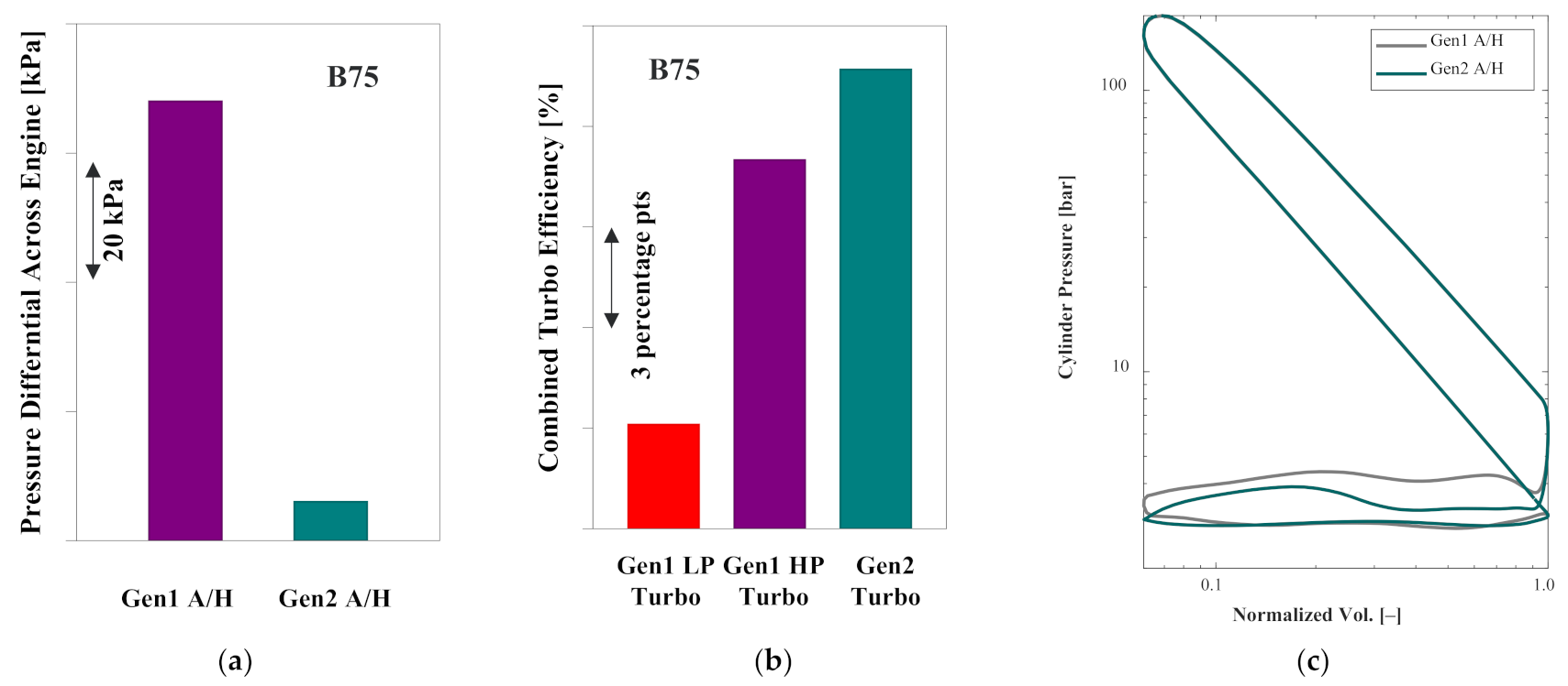
3.6. Gen2 Air-Handling Analysis

The Gen1 engine test results have clearly shown that although the off-the-shelf air-handling system was capable of meeting the air and EGR flow requirements, the efficiency of the gas exchange process needs to be improved. Therefore, it is of primary interest to refine the air-handling system when developing a Gen2 GCI engine. To that end, 1D system-level analysis was performed to evaluate and generate a Gen2 GCI air-handling, concept as shown in Figure 17. For the Gen2 air-handling analysis, the in-cylinder pressure, AHRR, and charge thermal boundary conditions (AFR, EGR, intake manifold pressure, and intake manifold temperature) from the Gen1 engine were imposed to focus on improving the gas exchange efficiency.
In the Gen2 GCI engine, an important feature was to replace the off-the-shelf, two-stage turbocharging system with a more efficient, prototype, single-stage VGT. As seen in Figure 17, the key engine operating points were well placed in the compressor map for the Gen2 turbocharger. In addition, the high-pressure EGR loop was upgraded by switching back the stock exhaust manifold and using a high-efficiency, single-stage EGR cooler to simultaneously reduce flow restrictions and achieve high cooling capacity.
Figure 18 shows that the Gen2 air-handling system delivered markedly improved gas exchange performance over the Gen1 system at B75, as evidenced by reduced pressure differential across the engine, enhanced turbocharger combined efficiency, and consequently a smaller pumping loop on the logP–logV diagram.
In Figure 19, it was predicted that PMEP was reduced by 43–54% across the four engine operating points. As a result, when combining the enhanced PMEP data from the Gen2 air-handling concept with the gross indicated experimental data from the Gen1 GCI engine (Figure 5), ISFCn-D and BSFC-D were improved by 2–4%, as shown in Figure 20, thereby demonstrating the performance enhancement potential for implementing a refined air-handling system.

4. Conclusions

Aimed at developing GCI as an enabling technology to meet CARB’s 0.027 g/kWh ultralow NOx standard, a Gen1 heavy-duty GCI engine concept was developed and implemented by taking an analysis-led design approach and utilizing a PPCI–diffusion combustion strategy. Based on the experimental and simulation results, the main conclusions are summarized as follows:
  • Utilizing the PPCI–diffusion GCI combustion strategy paired with customized combustion and air-handling concepts, Gen1 GCI delivered 85–95% lower smoke and 2–3% better ISFCg-D compared to the baseline diesel combustion at a 1 g/kWh engine-out NOx.
  • Three-dimensional CFD analysis revealed that the customized piston bowl geometry and fuel spray pattern combined with a tailored split fuel injection strategy enhanced the in-cylinder air utilization, thereby producing a faster and cleaner diffusion combustion process and leading to better fuel efficiency. Moreover, increasing the air flow and enhancing the charge cooling were shown to have a pronounced impact on furthering the air utilization benefit.
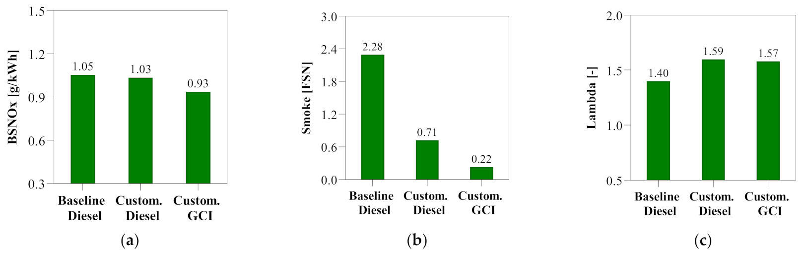
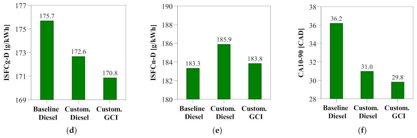
  • Gen1 engine combustion and air-handling concepts can be well harnessed to improve smoke and fuel efficiency for diesel combustion. Compared to the baseline, Gen1 diesel combustion produced 69% lower smoke and 1.8% better ISFCg-D at B50. When implementing GCI on the Gen1 engine, the smoke reduction was extended to 90%, while the ISFCg-D benefit was enhanced to 2.8% through the tailor-designed PPCI–diffusion combustion process.
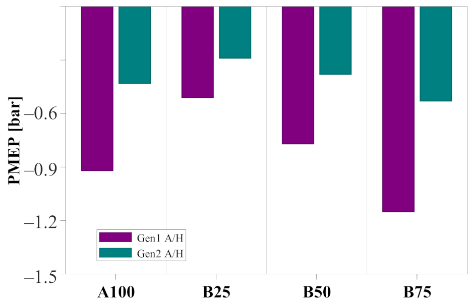
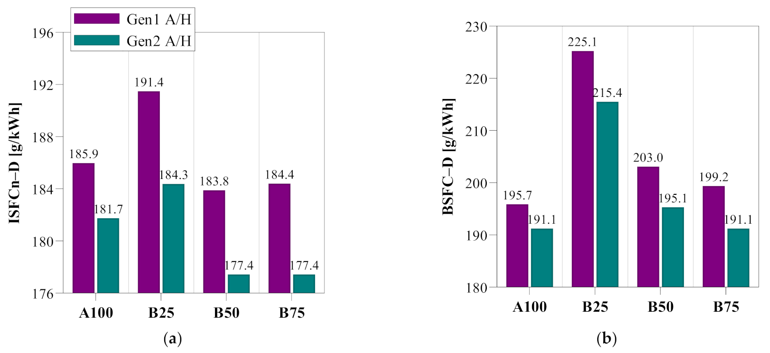
  • By upgrading the off-the-shelf, Gen1 air-handling system with a prototype, high-efficiency, single-stage VGT along with a less-restrictive and high-cooling-capacity high-pressure EGR loop, 1D system level analysis showed that gas exchange performance was markedly improved, with PMEP reduced 43–54% across the four operating points when imposing the Gen1 engine’s in-cylinder combustion process and charge thermal boundary conditions. Combining the enhanced PMEP results with the gross indicated experimental data from Gen1 GCI, ISFCn-D and BSFC-D were predicted to be improved by 2–4%, thereby demonstrating the performance enhancement potential of refining the air-handling system.

5. Future Work

The Gen2 air-handling system hardware components have been procured and integrated. In addition, a Gen2 combustion system concept has been developed [51] and installed on an engine to further enhance the PPCI–diffusion combustion process. Collectively, the Gen2 GCI engine has demonstrated improved steady-state fuel efficiency over the Gen1 engine. Moreover, by implementing customized engine calibration maps, the Gen2 engine successfully met the 0.027 g/kWh ultralow NOx standard over a hot FTP certification cycle using a production aftertreatment system. The next step is to demonstrate <0.027 g/kWh tailpipe NOx over combined hot and cold FTP cycles while achieving reduced CO2 emissions. Subsequently, component-level technologies including exhaust rebreathing, Millerization, and spark assistance will be integrated and evaluated to maximize GCI’s performance potential.

Author Contributions

Conceptualization, Y.Z., P.K., Y.P., M.T., and S.P.; methodology, Y.Z., P.K., Y.P., M.T., and S.P.; validation, Y.Z. and P.K.; formal analysis, Y.Z. and P.K.; investigation, Y.Z., P.K., Y.P., M.T., and S.P.; resources, Y.Z., M.T., and S.P.; data curation, Y.Z. and P.K.; writing—original draft preparation, Y.Z.; writing—review and editing, P.K., Y.P., M.T., and S.P.; supervision, Y.Z. and M.T.; project administration, Y.Z. and M.T. All authors have read and agreed to the published version of the manuscript.

Funding

This research was financially supported by Aramco Americas: Aramco Research Center-Detroit.

Data Availability Statement

Not applicable.

Acknowledgments

The authors would like to thank the facility team at Aramco’s Detroit Research Center for the indispensable support on hardware integration and engine testing. The authors also wish to express their gratitude to the IT division at Aramco Americas Research Centers for the support on the high-performance computing resources used in this work. The valuable technical support from Cummins Research and Technology and Borg Warner is gratefully acknowledged.

Conflicts of Interest

The authors declare no conflict of interest.

Nomenclature

°aTDCDegree after top dead center
BMEPBrake specific mean pressure
BSFCBrake specific fuel consumption
BSNOxBrake specific NOx emissions
CACrank angle
CA10–90Degree between crank angle of 10% heat released and crank angle of 90% heat released
CA50Crank angle of 50% heat released
CADCrank angle degree
COCarbon monoxide
CO2Carbon dioxide
EGRExhaust gas recirculation
ISFCIndicated specific fuel consumption
LambdaAir–fuel equivalence ratio
NOxNitrogen oxides
PinjFuel injection pressure
SOI1Start of the first fuel injection
SOI2Start of the second fuel injection

References

  1. California Air Resources Board (CARB) Heavy-Duty Low NOx Program. Available online: https://ww2.arb.ca.gov/our-work/programs/heavy-duty-low-nox (accessed on 28 December 2021).
  2. Robertson, W. California Air Resources Board Heavy-Duty Truck and Engine Plans. In Proceedings of the SAE 2017 Commercial Vehicle Congress, Rosemont, IL, USA, 18–20 September 2017. [Google Scholar]
  3. Dieselnet United States Heavy-Duty Vehicles GHG Emissions & Fuel Economy Standards. Available online: https://dieselnet.com/standards/us/fe_hd.php (accessed on 28 December 2021).
  4. Dempsey, A.; Curran, S.; Wagner, R. A Perspective on the Range of Gasoline Compression Ignition Combustion Strategies for High Engine Efficiency and Low NOx and Soot Emissions: Effects of In-Cylinder Fuel Stratification. Int. J. Engine Res. 2016, 17, 897–917. [Google Scholar] [CrossRef]
  5. Dec, J.; Yang, Y.; Dronniou, N. Boosted HCCI—Controlling Pressure-Rise Rates for Performance Improvements using Partial Fuel Stratification with Conventional Gasoline. SAE Int. J. Engines 2011, 4, 1169–1189. [Google Scholar] [CrossRef]
  6. Yun, H. A High Specific Output Gasoline Low-Temperature Combustion Engine. In Proceedings of the US DOE Vehicle Technologies Office Annual Merit Review Meeting, Arlington, VA, USA, 21 June 2018. [Google Scholar]
  7. Nakai, E.; Goto, T.; Ezumi, K.; Tsumura, Y.; Endou, K.; Kanda, Y.; Urushihara, T.; Sueoka, M.; Hitomi, M. MAZDA SKYACTIV-X 2.0L Gasoline Engine. In Proceedings of the 28th Aachen Colloquium Automobile and Engine Technology, Aachen, Germany, 10–12 October 2019. [Google Scholar]
  8. Manofsky, L.; Vavra, J.; Assanis, D.; Babajimopoulos, A. Bridging the Gap between HCCI and SI: Spark-Assisted Compression Ignition; SAE Technical Paper 2011-01-1179; SAE International: Detroit, MI, USA, 2011. [Google Scholar] [CrossRef]
  9. Kalghatgi, G.; Risberg, P.; Ångström, H. Partially Pre-Mixed Auto-Ignition of Gasoline to Attain Low Smoke and Low NOx at High Load in a Compression Ignition Engine and Comparison with a Diesel Fuel; SAE Technical Paper 2007-01-0006; SAE International: Detroit, MI, USA, 2007. [Google Scholar] [CrossRef]
  10. Kalghatgi, G.; Hildingsson, L.; Johansson, B. Low NOx and Low Smoke Operation of a Diesel Engine Using Gasoline-Like Fuels. J. Eng. Gas Turbines Power 2010, 132, 092803. [Google Scholar] [CrossRef]
  11. Manente, V.; Zander, C.; Johansson, B.; Tunestal, P.; Cannella, W. An Advanced Internal Combustion Engine Concept for Low Emissions and High Efficiency from Idle to Max Load Using Gasoline Partially Premixed Combustion; SAE Technical Paper 2010-01-2198; SAE International: Detroit, MI, USA, 2010. [Google Scholar] [CrossRef]
  12. Dempsey, A.; Reitz, R. Computational Optimization of a Heavy-Duty Compression Ignition Engine Fueled with Conventional Gasoline. SAE Int. J. Engines 2011, 4, 338–359. [Google Scholar] [CrossRef]
  13. Borgqvist, P.; Tunestal, P.; Johansson, B. Comparison of Negative Valve Over-lap (NVO) and Rebreathing Valve Strategies on a Gasoline PPC Engine at Low Load and Idle Operating Conditions. SAE Int. J. Engines 2013, 6, 366–378. [Google Scholar] [CrossRef]
  14. Desantes, J.; Payri, R.; Garcia, A.; Monsalve Serrano, J. Evaluation of Emissions and Performances from Partially Premixed Compression Ignition Combustion Using Gasoline and Spark Assistance; SAE Technical Paper 2013-01-1664; SAE International: Detroit, MI, USA, 2013. [Google Scholar] [CrossRef]
  15. Zhao, L.; Zhang, Y.; Pei, Y.; Zhang, A.; Ameen, M. CFD-Guided Evaluation of Spark-Assisted Gasoline Compression Ignition for Cold Idle Operation. Sustainability 2021, 13, 13096. [Google Scholar] [CrossRef]
  16. Paz, J.; Staaden, D.; Kokjohn, S. Gasoline Compression Ignition Operation of a Heavy-Duty Engine at High Load; SAE Technical Paper 2018-01-0898; SAE International: Detroit, MI, USA, 2018. [Google Scholar] [CrossRef]
  17. Zhang, Y.; Sommers, S.; Pei, Y.; Kumar, P.; Traver, M.; Cleary, D. Mixing-Controlled Combustion of Conventional and Higher Reactivity Gasolines in a Multi-Cylinder Heavy-Duty Compression Ignition Engine; SAE Technical Paper 2017-01-0696; SAE International: Detroit, MI, USA, 2017. [Google Scholar] [CrossRef]
  18. Zhang, Y.; Voice, A.; Pei, Y.; Traver, M.; Cleary, D. A Computational Investigation of Fuel Chemical and Physical Properties Effects on Gasoline Compression Ignition in a Heavy-Duty Diesel Engine. J. Energy Resour. Technol. 2018, 140, 102202. [Google Scholar] [CrossRef]
  19. Pei, Y.; Zhang, Y.; Kumar, P.; Traver, M.; Clear, D.; Ameen, M.; Som, S.; Probst, D.; Burton, T.; Pomraning, E.; et al. CFD-Guided Heavy Duty Mixing-Controlled Combustion System Optimization with a Gasoline-Like Fuel. SAE Int. J. Commer. Veh. 2017, 10, 532–546. [Google Scholar] [CrossRef]
  20. Wang, B.; Pamminger, M.; Vojtech, R.; Wallner, T. Impact of injection strategies on combustion characteristics, efficiency and emissions of gasoline compression ignition operation in a heavy-duty multi-cylinder engine. Int. J. Engine Res. 2018, 21, 1426–1440. [Google Scholar] [CrossRef]
  21. Sellnau, M.; Foster, M.; Moore, W.; Sinnamon, J.; Hoyer, K.; Klemm, W. Pathway to 50% Brake Thermal Efficiency Using Gasoline Direct Injection Compression Ignition. SAE Int. J. Adv. Curr. Pract. Mobil. 2019, 1, 1581–1603. [Google Scholar] [CrossRef]
  22. Sellnau, M.; Cho, K.; Zhang, Y.; Cleary, D. Pathway to 50% Brake Thermal Efficiency Using Gasoline Direct Injection Compression Ignition (GDCI). In Proceedings of the 28th Aachen Colloquium Automobile and Engine Technology, Aachen, Germany, 7–9 October 2019. [Google Scholar]
  23. Zhang, Y.; Cho, K.; Sellnau, M. Investigation on Combining Partially Premixed Compression Ignition and Diffusion Combustion for Gasoline Compression Ignition—Part 2: Compression Ratio and Piston Bowl Geometry Effects. SAE J. STEEP 2021, 2, 59–78. [Google Scholar] [CrossRef]
  24. Zhang, Y.; Sellnau, M. A Computational Investigation of PPCI-Diffusion Combustion Strategy at Full Load in a Light-Duty GCI Engine. SAE Int. J. Adv. Curr. Prac. Mobil. 2021, 3, 1757–1775. [Google Scholar] [CrossRef]
  25. Cung, K.; Ciatti, S. A Study of Injection Strategy to Achieve High Load Points for Gasoline Compression Ignition (GCI) Operation. In Proceedings of the ASME Internal Combustion Engine Division Fall Technical Conference, Seattle, WA, USA, 15–18 October 2017. [Google Scholar] [CrossRef]
  26. Zhang, Y.; Kumar, P.; Pei, Y.; Traver, M.; Cleary, D. An Experimental and Computational Investigation of Gasoline Compression Ignition Using Conventional and Higher Reactivity Gasolines in a Multi-Cylinder Heavy-Duty Diesel Engine; SAE Technical Paper 2018-01-0226; SAE International: Detroit, MI, USA, 2018. [Google Scholar] [CrossRef]
  27. Inagaki, K.; Mizuta, J.; Fuyuto, T.; Hashizume, T.; Ito, H.; Kuzuyanna, H.; Kawae, T.; Kono, M. Low Emissions and High-Efficiency Diesel Combustion Using Highly Dispersed Spray with Restricted In-Cylinder Swirl and Squish Flows; SAE Paper 2011-01-1393; SAE International: Detroit, MI, USA, 2011. [Google Scholar] [CrossRef]
  28. Hanson, R.; Curran, S.; Wagner, R.; Kokjohn, S.; Splitter, D.; Reitz, R. Piston Bowl Optimization for RCCI Combustion in a Light-Duty Multi-Cylinder Engine; SAE Technical Paper 2012-01-0380; SAE International: Detroit, MI, USA, 2012. [Google Scholar] [CrossRef]
  29. Dempsey, A.; Walker, N.; Reitz, R. Effect of Piston Bowl Geometry on Dual Fuel Reactivity Controlled Compression Ignition (RCCI) in a Light-Duty Engine Operated with Gasoline/Diesel and Methanol/Diesel; SAE Technical Paper 2012-01-0380; SAE International: Detroit, MI, USA, 2012. [Google Scholar] [CrossRef]
  30. Styron, J.; Baldwin, B.; Fulton, B.; Ives, D.; Ramanathan, S. Ford 2011 6.7L Power Stroke ® Diesel Engine Combustion System Development; SAE Technical Paper 2011-01-0415; SAE International: Detroit, MI, USA, 2011. [Google Scholar] [CrossRef]
  31. Kurtz, E.M.; Styron, J. An Assessment of Two Piston Bowl Concepts in a Medium-Duty Diesel Engine. SAE Int. J. Engines 2012, 5, 344–352. [Google Scholar] [CrossRef]
  32. Dolak, J.G.; Shi, Y.; Reitz, R.D. A Computational Investigation of Stepped-Bowl Piston Geometry for a Light Duty Engine Operating at Low Load; SAE Technical Paper 2010-01-1263; SAE International: Detroit, MI, USA, 2010. [Google Scholar] [CrossRef]
  33. Zha, K.; Busch, S.; Warey, A.; Peterson, R.; Kurtz, E. A Study of Piston Geometry Effects on Late-Stage Combustion in a Light-Duty Optical Diesel Engine Using Combustion Image Velocimetry. SAE Int. J. Engines 2018, 11, 783–804. [Google Scholar] [CrossRef]
  34. Tuner, M.; Johansson, B.; Keller, P.; Becker, M. Loss Analysis of a HD-PPC Engine with Two-Stage Turbocharging Operating in the European Stationary Cycle; SAE Technical Paper 2013-01-2700; SAE International: Detroit, MI, USA, 2013. [Google Scholar] [CrossRef]
  35. Kumar, P.; Zhang, Y.; Traver, M.; Watson, J. Tailored Air-Handling System Development for Gasoline Compression Ignition in a Heavy-Duty Diesel Engine. Front. Mech. Eng. 2021, 7, 611916. [Google Scholar] [CrossRef]
  36. Zhang, Y.; Kumar, P.; Tang, M.; Pei, Y.; Merritt, E.; Traver, M.; Popuri, S. Impact of Geometric Compression Ratio and Variable Valve Actuation on Gasoline Compression Ignition in a Heavy-Duty Diesel Engine. In Proceedings of the ASME Internal Combustion Engine Division Fall Technical Conference, Denver, CO, USA, 1–4 November 2020. [Google Scholar] [CrossRef]
  37. Pei, Y.; Pal, P.; Zhang, Y.; Traver, M.; Cleary, D.; Futterer, C.; Brenner, M.; Probst, D.; Som, S. CFD-Guided Combustion System Optimization of a Gasoline Range Fuel in a Heavy-Duty Compression Ignition Engine Using Automatic Piston Geometry Generation and a Supercomputer. SAE Int. J. Adv. Curr. Prac. Mobil. 2019, 1, 166–179. [Google Scholar] [CrossRef]
  38. Voice, A.; Tzanetakis, T.; Traver, M. Lubricity of Light-End Fuels with Commercial Diesel Lubricity Additives; SAE Technical Paper 2017-01-0871; SAE International: Detroit, MI, USA, 2017. [Google Scholar] [CrossRef]
  39. Gamma Technologies. GT-Suite: Engine Performance Application Manual (Version 2019); Gamma Technologies: Westmont, IL, USA, 2019. [Google Scholar]
  40. Kumar, P.; Zhang, Y.; Traver, M.; Cleary, D. Simulation-Guided Air System Design for a Low Reactivity Gasoline-Like Fuel under Partially-Premixed Combustion in a Heavy-Duty Diesel Engine; SAE Technical Paper 2017-01-0751; SAE International: Detroit, MI, USA, 2017. [Google Scholar] [CrossRef]
  41. Richards, K.J.; Senecal, P.K.; Pomraning, E. Converge Manual (Version 2.3); Convergent Science Inc.: Madison, WI, USA, 2018. [Google Scholar]
  42. Som, S.; Longman, D.; Aithal, S.; Bair, R.; Garcia, M.; Quan, S.; Richards, P.; Senecal, K.; Shethaji, T.; Weber, M. A Numerical Investigation on Scalability and Grid Convergence of Internal Combustion Engine Simulations; SAE Technical Paper 2013-01-1095; SAE International: Detroit, MI, USA, 2013. [Google Scholar] [CrossRef]
  43. Senecal, K.; Pomraning, E.; Richards, K.J.; Som, S. An Investigation of Grid Convergence for Spray Simulations Using an LES Turbulence Model; SAE Technical Paper 2013-01-1083; SAE International: Detroit, MI, USA, 2013. [Google Scholar] [CrossRef]
  44. Han, Z.; Reitz, R.D. Turbulence Modeling of Internal Combustion Engines Using RNG k-ε Models. Combust. Sci. Tech. 1995, 106, 267–295. [Google Scholar] [CrossRef]
  45. Reitz, R.; Diwakar, R. Structure of High-Pressure Fuel Sprays; SAE Technical Paper 870598; SAE International: Detroit, MI, USA, 1987. [Google Scholar] [CrossRef]
  46. Reitz, R.D. Modeling Atomization Processes in High Pressure Vaporizing Sprays. At. Spray Tech. 1987, 3, 309–337. [Google Scholar]
  47. Patterson, M.; Reitz, R. Modeling the Effects of Fuel Spray Characteristics on Diesel Engine Combustion and Emission; SAE Technical Paper 980131; SAE International: Detroit, MI, USA, 1998. [Google Scholar] [CrossRef]
  48. Schmidt, D.P.; Rutland, C.J. A New Droplet Collision Algorithm. J. Comp. Phys. 2000, 164, 62–80. [Google Scholar] [CrossRef]
  49. Frossling, N. Evaporation, heat transfer, and velocity distribution in two-dimensional and rotationally symmetrical laminar boundary-layer flow. NACA Tech. Memo. 1956, 168, 1–37. [Google Scholar]
  50. Liu, Y.; Jia, M.; Xie, M.; Pang, B. Enhancement on a Skeletal Kinetic Model for Primary Reference Fuel Oxidation by Using a Semidecoupling Methodology. Energy Fuels 2012, 26, 7069–7083. [Google Scholar] [CrossRef]
  51. Zhang, Y.; Pei, Y.; Meng, T.; Traver, M. A Computational Investigation of Piston Bowl Geometry and Injector Spray Pattern Effects on Gasoline Compression Ignition in a Heavy-Duty Diesel Engine. In Proceedings of the ASME Internal Combustion Engine Division Fall Technical Conference, Chicago, IL, USA, 20–23 October 2019. [Google Scholar] [CrossRef]
  52. Yang, J.; Golovitchev, V.; Redon, P.; Javier Lopez Sanchez, J. Numerical Analysis of NOx Formation Trends in Biodiesel Combustion Using Dynamic ϕ-T Parametric Maps; SAE Technical Paper 2011-01-1929; SAE International: Detroit, MI, USA, 2011. [Google Scholar] [CrossRef]
  53. Meng, T.; Pei, Y.; Zhang, Y.; Tzanetakis, T.; Traver, M.; Cleary, D.; Quan, S.; Naber, J.; Lee, S. Development of a Transient Spray Cone Angle Correlation for CFD Simulations at Diesel Engine Conditions; SAE Technical Paper 2018-01-0304; SAE International: Detroit, MI, USA, 2018. [Google Scholar] [CrossRef]
Figure 1. Overview of GCI combustion strategy.
Energies 15 01087 g001
Figure 2. Overview of the analysis-led design approach.
Energies 15 01087 g002
Figure 3. Impact of GCR and EGR on GCI performance in a 15 L heavy-duty diesel engine: (a) smoke; (b) BSFC-D; (c) BSFCV-D/smoke tradeoff.
Energies 15 01087 g003
Figure 4. Gen1 GCI engine system layout.
Energies 15 01087 g004
Figure 5. Overview of Gen1 GCI performance results: (a) BSNOx; (b) smoke; (c) AFR-D; (d) ISFCg-D; (e) ISFCn-D; (f) BSFC-D.
Energies 15 01087 g005
Figure 6. Cylinder pressure and AHRR for Gen1 GCI: (a) A100; (b) B25; (c) B50; (d) B75.
Energies 15 01087 g006
Figure 7. Experimental and simulated cylinder pressure for Gen1 GCI: (a) A100; (b) B25; (c) B50; (d) B75.
Energies 15 01087 g007aEnergies 15 01087 g007b
Figure 8. Comparison of key Gen1 GCI engine operating boundary between experimental data and model predictions: (a) BMEP; (b) external EGR; (c) AFR; (d) fuel flow; (e) air flow; (f) intake manifold pressure (IMP); (g) intake manifold temperature (IMT); (h) turbine inlet pressure; (i) turbine inlet temperature.
Energies 15 01087 g008aEnergies 15 01087 g008b
Figure 9. Comparison between experimental data and model predictions: (a) cylinder pressure (Pcyl); (b) NOx and soot.
Energies 15 01087 g009
Figure 10. In-cylinder GCI combustion behavior at B75 predicted by 3D CFD: (a) Pcyl and AHRR; (b) cross-sectional equivalence ratio and temperature contours.
Energies 15 01087 g010
Figure 11. Step-wise simulation boundary conditions and global combustion behavior for the customized combustion and A/H system concept at B75.
Energies 15 01087 g011
Figure 12. Comparison of in-cylinder air utilization characteristics for GCI at CA50 and CA75: (a) Phi > 1; (b) Phi > 2.
Energies 15 01087 g012
Figure 13. Global combustion behavior for Baseline-Diesel, Gen1-Diesel, and Gen1-GCI at B50.
Energies 15 01087 g013
Figure 14. Overview of performance results for Baseline-Diesel, Gen1-Diesel, and Gen1-GCI at B50: (a) BSNOx; (b) smoke; (c) lambda; (d) ISFCg-D; (e) ISFCn-D; (f) CA10–90.
Energies 15 01087 g014aEnergies 15 01087 g014b
Figure 15. Overview of the performance results from fuel injection strategy investigation at B50: (a) BSNOx; (b) smoke; (c) ISFCg-D; (d) BSFC-D; (e) CA50; (f) MPRR.
Energies 15 01087 g015aEnergies 15 01087 g015b
Figure 16. Global combustion behavior under varying fuel injection strategies at B50: (a) impact of Q1; (b) impact of Pinj.
Energies 15 01087 g016
Figure 17. Gen2 GCI engine system layout.
Energies 15 01087 g017
Figure 18. Comparison of gas exchange performance between Gen1 A/H and Gen2 A/H at B75: (a) pressure differential across engine; (b) combined turbocharger efficiency; (c) logP–logV.
Energies 15 01087 g018
Figure 19. Comparison of PMEP between Gen1 A/H and Gen2 A/H.
Energies 15 01087 g019
Figure 20. Comparison of fuel efficiency results between Gen1 A/H and Gen2 A/H: (a) ISFCn-D; (b) BSFC-D.
Energies 15 01087 g020
Table 1. Properties of test fuels (data from [26,36]).
ULSD93 RON Gasoline
IBP (°C)16735
T10 (°C)21252
T50 (°C)25781
T90 (°C)309149
FBP (°C)344199
Density at 15.56 °C (g/mL)0.8450.733
Kinematic viscosity (cSt)2.490.55
Aromatics (vol%)27.725.7
Olefins (vol%)1.810.1
Saturates (vol%)70.564.2
Sulfur (ppm)3.93.4
H/C ratio (–)1.791.97
Cetane number (CN) (–)46.621.0
Research octane number (RON) (–)-92.5
Motoring octane number (MON) (–)-83.8
Lower heating value (MJ/kg)42.8743.4
Table 2. Primary Converge sub-models (adapted from [24]).
Models
InjectionBlob
EvaporationFrossling
BreakupKH-RT
CollisionNTC
Chemistry solverSAGE
Gas-phase fuel surrogatePrimary reference fuel (PRF) blend
Chemical kinetic mechanismLiu et al. reduced PRF mechanism
NOx4 species and 13 reactions
SootHiroyasu–NSC
TurbulenceRNG k-ε
Wall heat transferO’Rourke and Amsden
Table 3. Key specifications for the baseline engine and the Gen1 GCI engine.
BaselineGen1 GCI
Engine-out NOx target (g/kWh)1.0
GCR (–)17.316.5
Piston bowlProductionCustomized step-lipped
Number of nozzle holes (–)89
Spray inclusion angle (°)148152
Injector hydraulic flow rate (–)constant
Swirl ratio (–)1.0
Turbocharging systemSingle-stage VGTTwo-stage FGT with inter-stage cooling
EGR layoutHigh-pressure loop EGR with single-stage coolingHigh-pressure loop EGR with two-stage cooling
Table 4. Main GCI operating boundary conditions at the four test points.
93 RON Gasoline1147 rpm/
20 bar BMEP (A100)
1375 rpm/
5 bar BMEP
(B25)
1375 rpm/
10 bar BMEP
(B50)
1375 rpm/
15 bar BMEP
(B75)
Pinj (bar)160055014501900
SOI1 (°aTDC)−30
SOI2 (°aTDC)−3−7−6−6
Q1 (-)0.10.50.30.1
CA50 (°aTDC)13859
EGR (%)28.340.437.536.9
AFR-D (-)18.828.522.821.8
Lambda (-)1.31.971.571.51
Int. man. pressure (bar, abs)3.251.562.233.1
Publisher’s Note: MDPI stays neutral with regard to jurisdictional claims in published maps and institutional affiliations.

