Article

Mutual Diffusion of Model Acceptor/Donor Bilayers under Solvent Vapor Annealing as a Novel Route for Organic Solar Cell Fabrication

Faculty of Physics Astronomy and Applied Computer Science, Jagiellonian University, ul. Łojasiewicza 11, 30-348 Kraków, Poland
*
Authors to whom correspondence should be addressed.
Energies 2022, 15(3), 1033; https://doi.org/10.3390/en15031033
Submission received: 20 December 2021 / Revised: 24 January 2022 / Accepted: 26 January 2022 / Published: 29 January 2022

Abstract

:
The fabrication of bulk heterojunction organic solar cells (OSCs) is primarily based on a phase demixing during solution deposition. This spontaneous process is triggered when, as a result of a decrease in the solvent concentration, interactions between donor and acceptor molecules begin to dominate. Herein, we present that interdiffusion of the same molecules is possible when a bilayers of donors and acceptors are exposed to solvent vapor. Poly(3-hexyl thiophene) (P3HT), and poly[N-9′-heptadecanyl-2,7-carbazole-alt-5,5-(4′,7′-di-2-thienyl-2′,1′,3′-benzothiadiazole) (PCDTBT) were used as donors and two types of fullerene derivatives were used as acceptors: phenyl-C61-butyric acid methyl ester (PC60BM) and phenyl-C71-butyric acid methyl ester (PC70BM), Secondary ion mass spectrometry depth profiling revealed that the interpenetration of donors and acceptors induced by solvent vapor annealing was dependent on solvent vapor and component compatibility. Exposure to chloroform vapor resulted in a complete intermixing of both components. The mutual mixing increased efficiency of inverted solar cells prepared by solvent vapor annealing of model donor/acceptor bilayers. These results provide a new means for mixing incompatible components for the fabrication of organic solar cells.

1. Introduction

Organic solar cells (OSCs) have attracted significant attention as new sources of renewable energy due to their low cost, light weight and compatibility for large-format solution deposition production technologies. Phenomenal improvement has taken place in recent years, and the power conversion efficiency (PCE) of state-of-the-art devices is comparable with commercially available silicon solar cells [1,2,3,4]. This breakthrough could not have been achieved without new materials [5] and has also been attributed to a better understanding of the factors that affect OSC fabrication and of the relationship between microstructure and charge generation [4,6,7,8].
The basic principles of organic solar cell operation are similar to those for inorganic devices: excitons created by adsorbed light dissociate and free charge carriers move to external electrodes. Lower degrees of order of organic semiconductors result in higher exciton binding energies, lower charge carrier mobility, and higher absorption coefficients. To promote exciton dissociation, electron acceptors should be placed in the vicinity of exciton formation regions in donor materials with an uninterrupted path to the external electrodes. The simplest structure fulfilling such requirements is a donor and acceptor bilayer sandwiched between electrodes.
This heterojunction concept for organic photovoltaic devices was first investigated by Tang [9], who showed that a layer of acceptor materials placed between cathode and donor layers increased the efficiency of low molecular weight organic semiconductor solar cells. Then, fullerene C60 with its high ionization potential and high electron mobility was shown to be an excellent candidate as an acceptor material for highly efficient organic solar cells [10]. One of the first fullerene devices had fullerene deposited on top of thin poly(2-methoxy-5-(2′-ethylhexyloxy)-p-phenylene vinylene) film but had no more that 0.04% efficiency. High efficiency light harvesting, exciton dissociation, and charge carrier transport properties have since been developed for these active layers.
A major breakthrough was achieved with the introduction of a bulk heterojunction [11], a structure characterized by an interpenetrating network of large interfaces between continuous donor and acceptor domains. Due to the short lifetimes of excitons in organic semiconductors, their diffusion length is limited to ca. 10 nm [12,13]. This limits the characteristic domain size of nanostructured layers. Fortunately, desired structures spontaneously form due to phase separation phenomena during the solution coating of thin multicomponent films on substrates [14].
Studies on model systems, such as poly(3-hexyl thiophene) (P3HT): phenyl-C61-butyric acid methyl ester (PC60BM), have shown a number of the factors that influence phase separation allow for the precise control of this spontaneous process to obtain desired layer morphology [8,15,16,17,18,19,20,21]. A lot of work has been done to optimize the coating conditions of different blends based on solvent composition, constituent blend composition, and film thickness. Additional studies have been conducted to understand the relationships between the obtained structures and solar cell properties. Others have also reported on modifying the properties of these layers. Thermal annealing has been the most often applied post-treatment method, which typically results in increased P3HT:PC60BM solar cell efficiency by nearly an order of magnitude [22] due to the enhanced crystallinity of semiconducting materials. The same effect can be achieved by microwave irradiation [23]. Cell efficiency can also be enhanced by reorganizing the nanostructure of the thin films by controlling the drying time, i.e., solvent annealing [24] or solvent vapor annealing [25].
Interactions between solutes and solvents are key parameters that affect the demixing process. Because the number of macromolecule types with the desired electro-optical properties is limited, the choice of solvent for a selected donor and acceptor mixture is crucial for obtaining an optimal OSC structure. Theoretical and experimental studies of phase separation in these ternary systems provide some guidance, but each new donor/acceptor pair would require optimization. This is because spontaneous demixing occurs rapidly and is extremely sensitive to slight changes in fabrication conditions. In their seminal paper, Treat and coworkers [26] revealed thermally induced miscibility in P3HT:PC60BM and indicated the possibility of using the mixing process to obtain mutually penetrating domains. Efficient solar cells were fabricated by thermal annealing of P3HT:PC60BM bilayers [27,28]. Further studies on thermally induced intermixing in P3HT/PC60BM system showed complicated interplay between P3HT crystallization and PC60BM interdiffusion [8,21]. The evolution of the P3HT:PC60BM solar cell performance is shortly summarized in Table 1.
The goal of this study is to apply an intermixing method for the fabrication of bulk heterojunction organic solar cells. For the first time, we show that the interdiffusion of acceptor/donor bilayers can be induced by solvent vapor annealing and is much slower than thermal intermixing. The process can be readily controlled by choice of solvent, which may be more compatible with the first or second component promoting higher mobility. To show this phenomenon can be utilized in fabricating organic solar cells, we prepared a series of devices with P3HT:PC60BM and Poly[N-9′-heptadecanyl-2,7-carbazole-alt-5,5-(4′,7′-di-2-thienyl-2′,1′,3′-benzothiadiazole) (PCDTBT): phenyl-C71-butyric acid methyl ester (PC70BM) bilayers exposed to chloroform vapor for different periods. Morphology and performance comparisons of devices prepared herein were qualitatively consistent with recently published simulation impact results of vertical composition profiles on OSC operation.

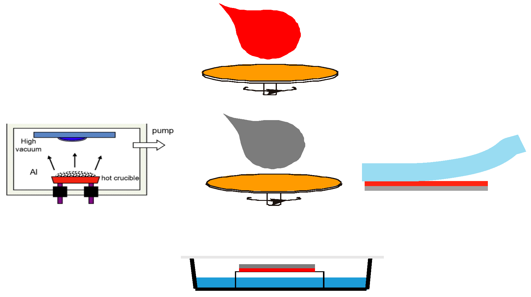
2. Materials and Methods

Materials. Electronic grade regioregular poly(3-hexyl thiophene) was purchased from Rieke Metals, Inc. (Lincoln, NE, USA) with a number-average molecular mass Mn = 34 kDa and a polydispersity index of 2.7. Poly[N-9′-heptadecanyl-2,7-carbazole-alt-5,5-(4′,7′-di-2-thienyl-2′,1′,3′-benzothiadiazole) a number-average molecular mass Mn = 16.2 kDa and a polydispersity index of 2.15 was purchased from Osilla Ltd. (Sheffield, UK). Phenyl-C61-butyric acid methyl ester and phenyl-C71-butyric acid methyl ester were obtained from Solenne BV (Groningen, The Netherlands). Toluene, chloroform, dichloroethane, tetrahydrofurane, and ZnO ink were purchased from Sigma-Aldrich. All materials and solvents were used as received.
Interdiffusion of bilayers. Silicon wafers (Si-Mat GmbH, Kaufering, Germany) were cut into 10 × 10 mm pieces, cleaned by sonification in toluene for 15 min, rinsed with toluene, and dried with N2 steam. P3HT and PCDTBT were dissolved in chlorobenzene to form a 15 mg/mL and 5mg/mL solutions, respectively. Before casting, the solutions were heated at 60 °C overnight inside an argon-filled glovebox. The prepared solution was filtered through a 0.45-μm syringe filter and spun-cast onto the silicon pieces at 1000 rpm in the glovebox. Next, the samples were transferred to a vacuum chamber onto which a layer of PC60BM molecules was thermally evaporated. The layer thickness was monitored using a quartz microbalance and was adjusted to 50 nm. The bilayer samples were then transferred back to the glovebox and exposed to different solvent vapors for different time periods.
Solar cell fabrication and characterization. Solar cells were fabricated using a sequential casting routine and thin-film transfer-printing technique [29,30]. Ossila glass substrates (S211) with patterned ITO electrodes were cleaned by sonication in 2-propanol for 15 min and dried under N2 flux. Substrates were treated with oxygen plasma, and zinc oxide nanoparticles were spun cast onto the substrates at 4000 rpm. The prepared thin films were annealed at 120 °C for 20 min. P3HT was dissolved in 1,2-dichlorobenzene to form a 10 mg/mL solution. The solution was heated at 60 °C overnight inside an argon-filled glovebox and filtered through a 0.45-µm syringe filter prior to spin-casting at 1500 rpm onto prepared ZnO thin films to form an ~30 nm layer. PC60BM was dissolved in dichloromethane to form an 8 mg/mL solution. Before casting, the solution was heated at 60 °C overnight inside the glovebox. The prepared solution was filtered through a 0.45-µm syringe filter and spun cast at 1500 rpm onto the prepared ZnO/P3HT thin films to form an ~90 nm film.
PCDTBT/PC70BM bilayers were prepared by thin-film transfer-printing technique as described in ref [29]. First PC70BM layer was spun casted from on top of ZnO from 1,2-dichlorobenzene solution (10 mg/mL) filtered through a 0.45 µm syringe filter. PCDTBT layer was prepared on top of silicon wafer covered with thin film of polystyrene sulfonate (PSS) by solution casting from 5 mg/mL solution in chlorobenzene. Next flat elastomeric poly(dimethylsiloxane) (PDMS) stamp was press against the polymer film. After dissolution of the PSS sacrificial layer in a water bath the stamp with grabbed PDCTBT film was placed on top of PC70BM layer and gently peeled.
Such prepared bilayers were exposed to chloroform vapor for different durations. Finally, 100 nm silver electrodes were thermally evaporated to form eight 4-mm2 devices on each substrate. The solar cells were characterized in an inert atmosphere under white light illumination from a solar simulator AM1.5 (Newport, Irvine, CA, USA) at 100 mW/cm2; current-voltage characteristics were acquired by a computer-controlled source meter unit, Keithley 2400 (Keithley Instruments, Solon, OH, USA).
Thin film characterization. The TOF-SIMS experiments were performed on an ION TOF TOF:SIMS V instrument (Munster, Germany), equipped with a liquid metal ion source and a cesium ion source. Sample depth profile (dSIMS) were obtained in dual beam mode. Briefly, a 500 eV Cs+ ion beam was used to sputter-coat a 500 × 500 μm2 area and a Bi3+ 30 keV ion beam was used to analyze a 200 × 200 μm2 area concentric to the sputtered surface.
An Atomic Force Microscope Agilent 5500 instrument was used to investigate the topography of the free surfaces of the thin films. Set-points and gains were adjusted to each measurement to obtain clear images without noise. Each topography was investigated by collecting images at several randomly chosen areas. The images were processed using Gwyddion 2.39 software.

3. Results and Discussion

All experiments described herein include bilayers of acceptors on top of polymer donor. Regioregular poly(3-hexyl thiophene) (P3HT) and poly[N-9′-heptadecanyl-2,7-carbazole-alt-5,5-(4′,7′-di-2-thienyl-2′,1′,3′-benzothiadiazole) (PCDTBT) were used as model donor while phenyl-C61-butyric acid methyl ester (PC60BM) and phenyl-C71-butyric acid methyl ester (PC70BM) were used as model acceptor. The polymer layer was spun-coated from dichlorobenzene solution, whereas the top layer was prepared by thermal evaporation [31], subsequent casting from dichloroethane [32] or transfer method [29].The thicknesses of the evaporated PC60BM layer were monitored by quartz microbalance. The acceptor/donor bilayers were solvent vapor annealed in a sealed container partially filled with selected solvent. The samples were always kept separate from liquid solvents. Silicon dices were used as substrates when comparing interdiffusion under different solvent vapors; ITO/ZnO transparent conductive electrodes were used for fabricating solar cells. An experimental scheme is depicted in Figure 1.

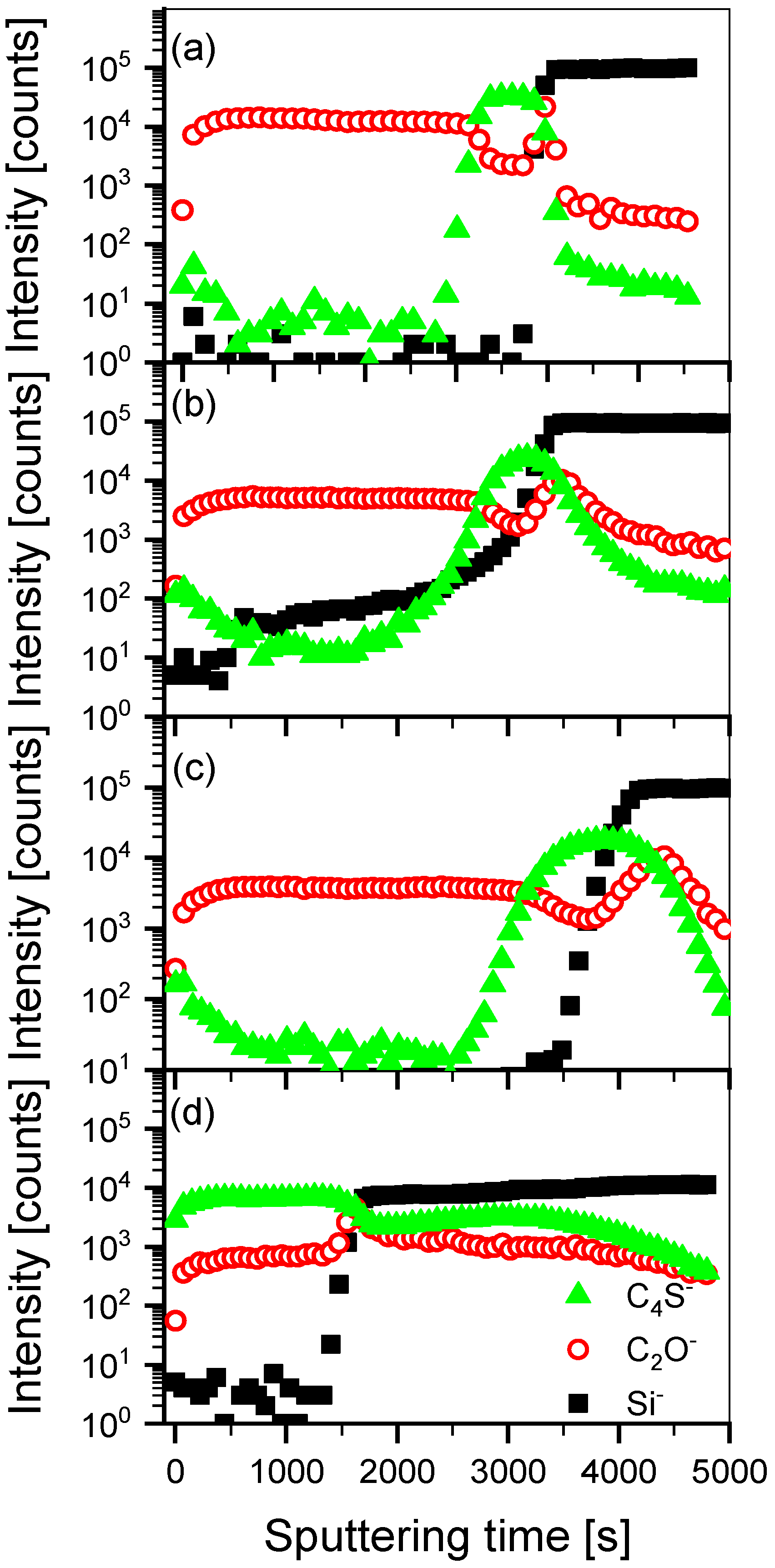
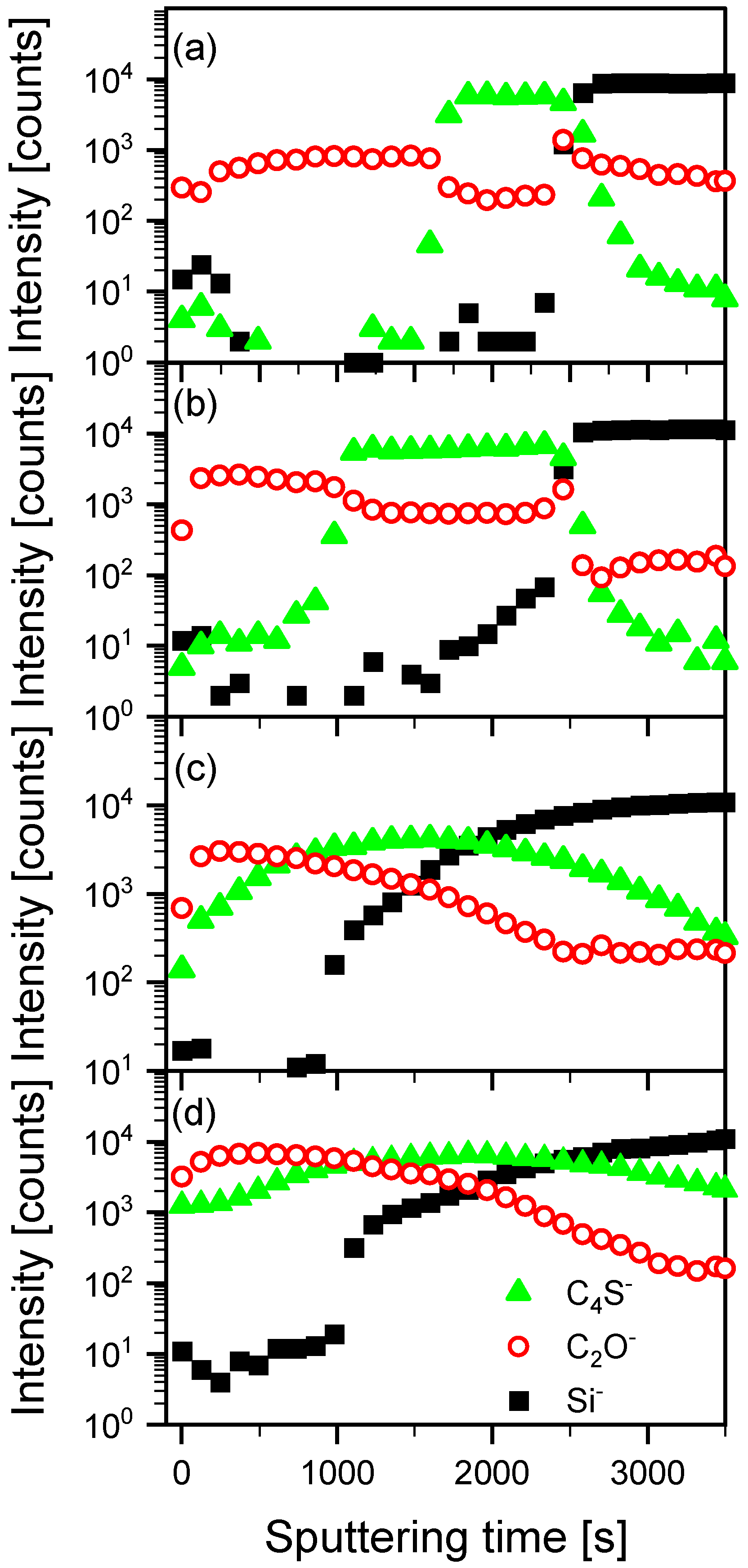
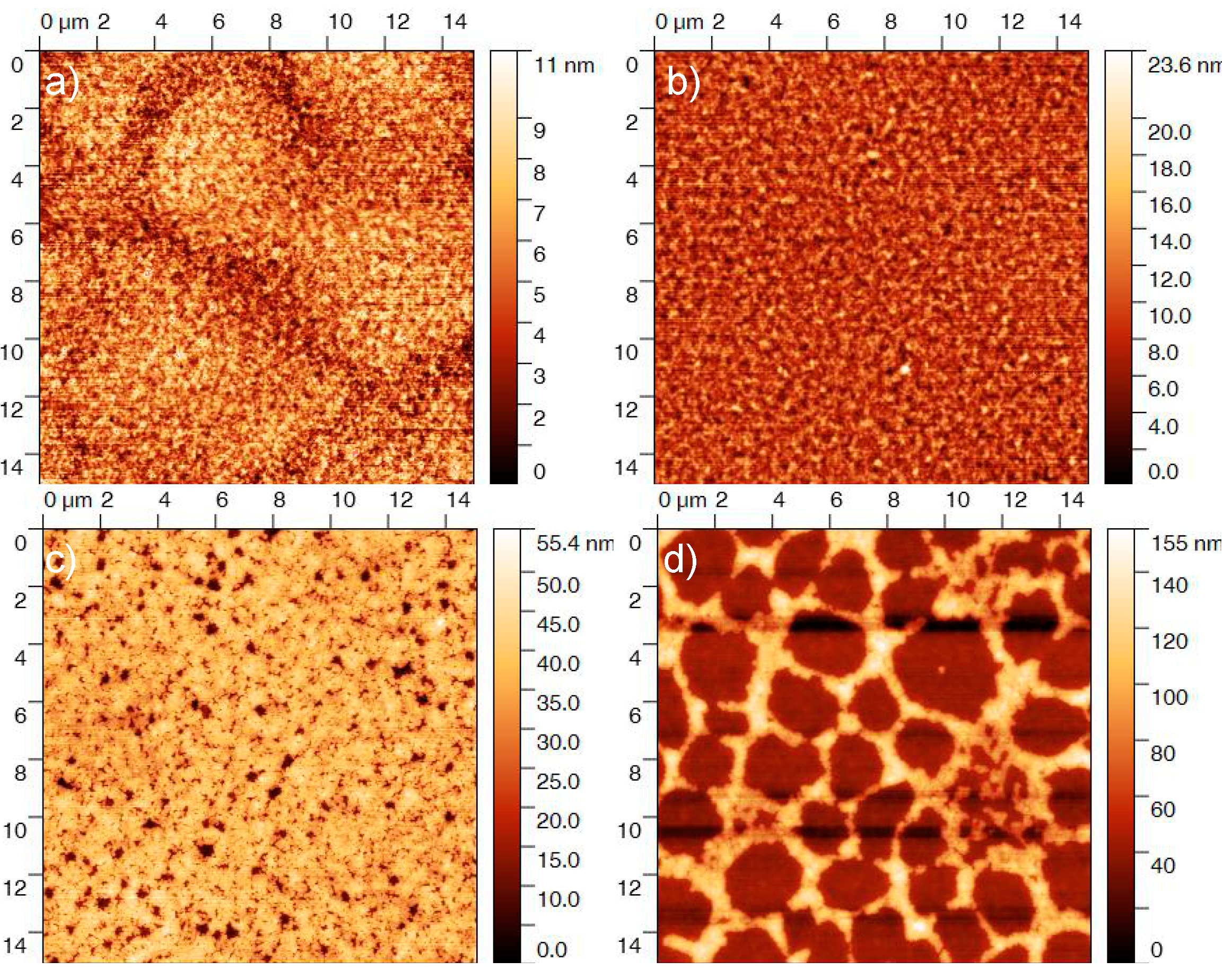
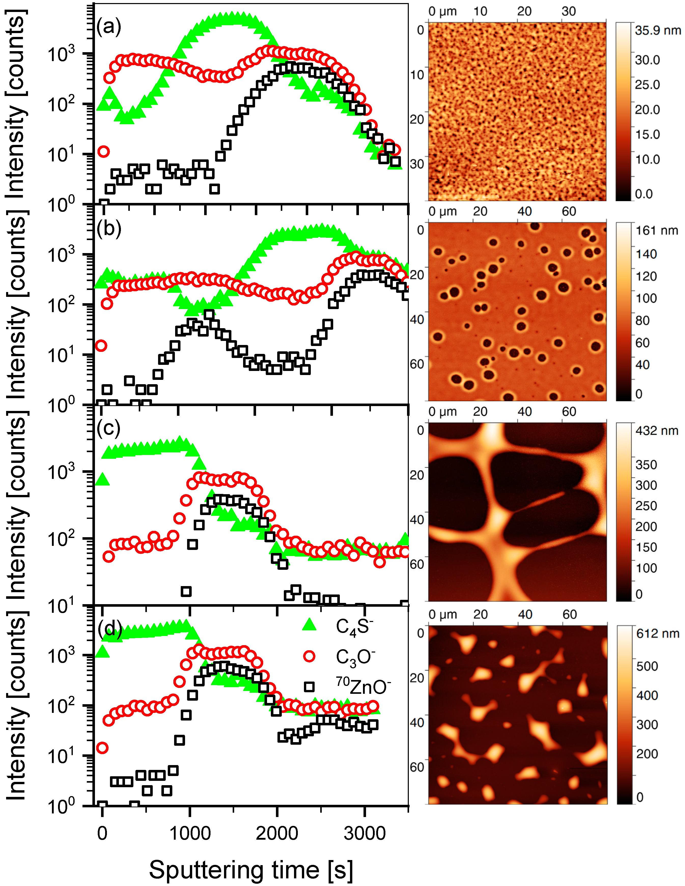
3.1. Mutual Diffusion of Acceptor/Donor Bilayers
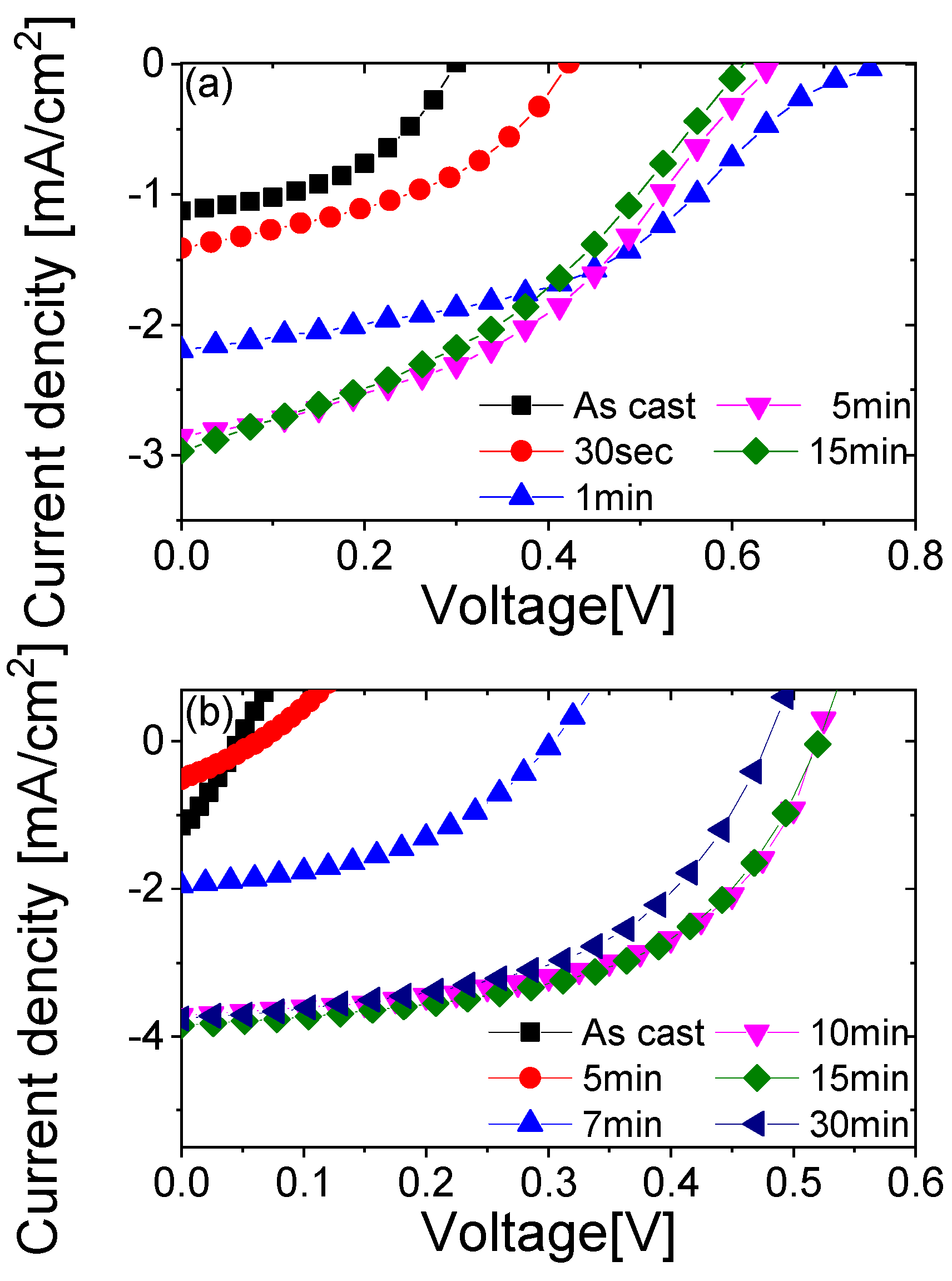
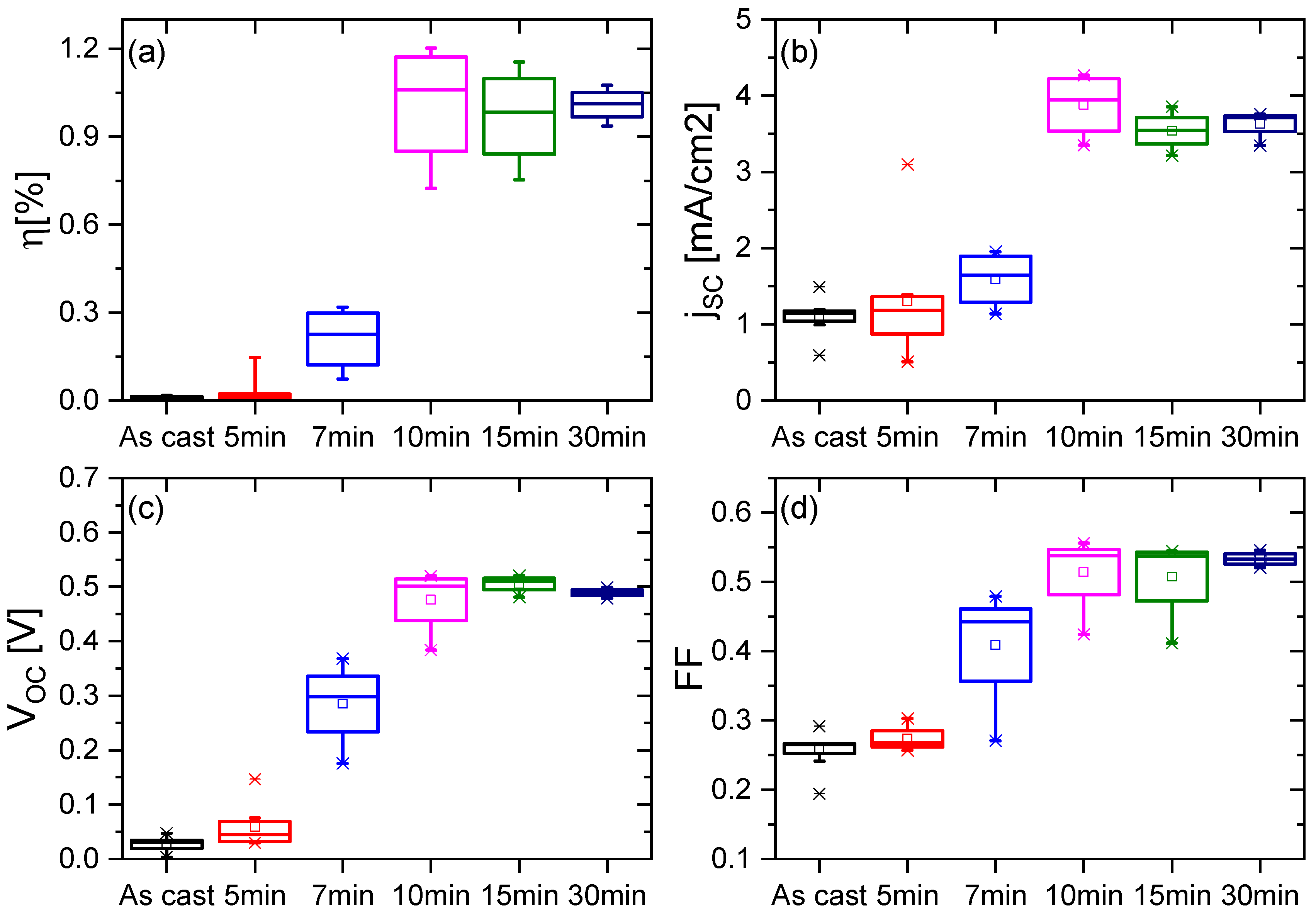
P3HT thin films covered with PC60BM layers prepared by thermal evaporation were exposed to three solvent vapors: dichloroethane (DCE), tetrahydrofurane (THF) and chloroform. Compatibility between organic macromolecules and solvents were predicted based on solubility parameters δ. The solubility parameters of model acceptors and donors are: δ = 21–22 MPa1/2 for PC60BM [33], δ = 12.8–13.1 MPa1/2 for P3HT [34] and δ = 22.8 MPa1/2 for PCDTBT [35]. The three solvents were selected based on their compatibility with only one component or with both. Dichloroethane, δ = 20.2 MPa1/2 [36], is a good solvent for fullerene derivatives and does not dissolve P3HT nor PCDTBT and was later used as an orthogonal solvent in sequential casting. Tetrahydrofurane, δ = 19.4 MPa1/2 [36], dissolves polythiophene well and PC60BM only slightly. Chloroform, δ = 19 MPa1/2 [36], is known to be a good solvent for both PC60BM and P3HT and is often used to fabricate bulk heterojunction organic solar cells.
dSIMS profiles of the bilayers prior to and after 1 h exposure to vapors are shown in Figure 2. The depth profiles monitor variation in composition as a function of sputtering time. For all silicon substrate samples, C4S signals (green solid triangles) were used to determine P3HT content, C2O signals (red open circles) for PC60BM content, and Si signals (black solid squares) were used to locate interfaces with substrates. The quantitative conversion of sputtering time to intermixed structure depth of P3HT and PCBM is not straightforward [28]; thus, we presented the profiles as functions of sputtering time.
The dSIMS profiles revealed that an initially sharp interface between PC60BM and polythiophene layers (Figure 2a) slightly broadened when exposed to THF (Figure 2b) or DCE (Figure 2c) vapors, whereas a single intermixed layer was formed upon exposure to chloroform vapor (Figure 2d). Sulfur-containing cluster signal characteristics for polythiophene in the top layer increased by an order of magnitude for samples treated with DCE and THF, whereas for chloroform, this value increased by half that value for pure P3HT. All samples were prepared under the same conditions, and the initial thicknesses of both fullerene derivative (44 nm) and polthiophene (55 nm) were the same for all samples. The bilayer depth profiles indicated large differences in PC60BM and P3HT sputtering efficiencies. Another factor influencing strongly shape of depth profiles obtained by ion sputtering methods is the topography of analyzed films [37]. In the profile corresponding to the as-prepared bilayer sample, the steep increase in Si signal from the substrate was accompanied by a rapid signal decrease for polythiophene. In contrast, for samples exposed to chloroform vapor, the C4S signal faded long after the silicon signal increased after 1500 s of sputtering (Figure 2d). This indicated that the initially flat surface of bilayer (Figure 2a) was roughened when exposed to chloroform vapor. Qualitatively, a similar relationship between the degree of acceptor and donor interdiffusion and the type of solvent observed for the PC70BM/PCDTBT layers (not shown).
Detailed analyses of PC60BM/P3HT and PC70BM/PCDTBT bilayer evolution under solvent vapor annealing in chloroform vapor are presented in Figure 3 and Figure 4. Presented in Figure 3 dSIMS profiles show progressive mutual penetration of PC60BM and P3HT over time. While initially sharp, the PC60BM/P3HT interface broadened after 30 min, and the sulfur signal in the top PC60BM rich layer only slightly increased. The interface flattened after 45 min and completely diminished after one hour. Detailed analysis of dSIMS profiles presented in Figure 4 reveals that at the beginning the interface between PC60BM and PCDTBT moves toward free surface (Figure 4b) and it starts to broaden after 45 min. In addition increase in the silicon signal is observed already after 1000 s of sputtering for samples treated for 45 min and longer.
A systematic broadening of the substrate interface as determined from silicon signals indicated increased free surface corrugation. This observation is supported by studies on the evolution of free surface of bilayers exposed to chloroform vapor. Topographic pictures presented in Figure 5a–d show a systematic wrinkling of PC60BM/P3HT bilayer surfaces with time. Initially, surface undulation amplitude increased (compare Figure 5a,b), followed by the formation of small holes (Figure 5c), and, after 60 min a structure typical of late stage dewetting phenomenon was observed (Figure 5d). For PC60BM/PCDTBT (see Figure S1) high corrugation of the free surface appears after 45 min of chloroform vapor treatment but no structure typical of late stage dewetting were observed within the experiment. Quenching of conjugated polymers (donors) fluorescence caused by interactions with acceptors (PC60MB/PC70BM) allows real-time observation of the intermixing processes using fluorescent microscopy. Presented in Figure S2 fluorescent micro-graphs show the initial formation of round domains (intermixed areas) that grow with time to form finally a structure typical of dewetting. We hypothesize that under solvent vapor annealing domains of saturated donor:acceptor mixtures are formed, and this process may be followed by dewetting of excess of material.

3.2. Solar Cells

To study the influence of the interdiffusion in acceptor/donor under solvent vapor annealing on the performance of solar cells, a series of devices on ZnO-covered ITO/glass electrodes were prepared. First, ZnO ink was cast on top of patterned ITO/glass substrates and annealed on a hotplate. Next, PC60BM/P3HT bilayers were prepared by sequential casting from orthogonal solvents while PCDTBT/PC70BM bilayers were prepared by transfer method [29,30]. Next bilayers were exposed to chloroform vapor in the same manner as the scheme depicted in Figure 1. Finally, metallic electrodes (Ag) were thermally evaporated through a shadow mask to form eight independent devices on one substrate. The active area of a single devices was 2 × 2 mm.
SIMS profiles and AFM images obtained for samples exposed to chloroform vapor for various time periods showed that the changes in the substrate from silicon to ZnO did not significantly affect the interdiffusion process (Figure 6 and Figure S3). The C4S signals (green solid triangles) were used to determine donor profile, the C3O signals (red open circles) were used for acceptors, and the 70ZnO signals (black open squares) were used to locate the cathode interface. The PC60BM component interpenetrated the polymer layer slightly during casting, and the interface between fullerene derivative and the P3HT was much broader than samples prepared with thermal evaporation (compare Figure 2a and Figure 3a). Broadening of the interface between PC70BM and PCDTBT was also observed for samples prepared by transfer method (see Figure S3).
The dSIMS profiles indicated a complete mixing of both phases after 10 min solvent vapor treatment. AFM topographic images of samples exposed to solvent vapor longer than 10 min showed structures typical of the late stages of the dewetting process. SIMS composition maps (see Figure S4 in Supporting Materials) indicated the surfaces of lower domains were reached in sulfur-containing component, whereas the P3HT contents in higher domains were lower.
Representative current voltage characteristics of solar cells prepared by solvent vapor annealing of the bilayers are presented in Figure 7. To avoid unpredictable effects of solvent vapor annealing on PEDOT:PSS, an organic film typically used as a hole-transport layer, the inverted geometry of solar cells with the ZnO transparent electrode was chosen. Initially, the acceptor layer (PC70BM) was in contact with ZnO, the donor PCDTBT with Ag electrode, and the contact area between donor and acceptor was relatively small. As seen in Figure 7a), the current-voltage curves shifted down the fourth quarter of the coordinate system with the solvent vapor annealing time as the intermixing of PC70BM and PCDTBT proceeded. Significantly lower current values obtained for devices prepared by the layer transfer method may result from the partial degradation of the polymer due to contact with water.
The initial layer arrangement of P3HT/PC60BM devices was chosen to mimic structures classified as unfavorable for charge transport [7] to better show the effects of bulk heterojunction formation due to the mutual diffusion of acceptor and donor. This was reflected in the shape of the current-voltage characteristics of the as-prepared devices. Large slopes of almost linear I–V profiles and low values of the open circuit voltage VOC were largely due to energy mismatch levels between the lower layer (P3HT) and the cathode (ZnO) and the upper layer (PC60BM) and the anode (Ag).
The I–V curves for devices prepared by solvent vapor annealing evolved with treatment time. The open circuit voltage monotonically increased to reach values close to 0.5 V (PC60BM/P3HT) and 0.65 (PC70BM/PCDTBT) typical for devices prepared on ZnO; this was accompanied by increased short circuit current. The maximum values of short circuit currents and open voltages were observed after 10 min of solvent vapor annealing for PC60BM/P3HT bilayers and after five minutes for PC70BM/PCDTBT. In case of the PC60BM/P3HT it corresponds to the moment when structures typical for late stage of dewettig begins to form. The I–V curves took the shape of a typical solar cell as reflected in an increased fill factor, however for PC70BM/PCDTBT solar cells decrease in FF is observed for longer treatment times. These performance parameters are summarized for each solvent vapor treatment time in Figure 8 and Figure S5 (at least eight per data point) under AM1.5G solar simulator illumination. Monotonous increases were observed for efficiency η (Figure 8a and Figure S5), short circuit current ISC (Figure 8b and Figure S5), open voltage VOC (Figure 8c and Figure S5) and fill factor FF (Figure 8d and Figure S5) for devices annealed up to 10 min. Later, nearly all parameters stabilized, but the spread of their values decreased. Changes in I–V curves are reflected in the shunt resistances Rsh which for both systems increase with solvent vapor annealing time (Tables S1 and S2 and Figure S6). However in the PCDTBT:PC70BM system after initial increase, Rsh drops for annealing times above 1 min. In this system also series resistance Rs is considerably larger than in the P3HT:PC60BM system which can be caused by layer transfer, through water, method which can lead to higher values of Rs in the system.
An analysis of the data in Figure 8, Figures S5 and S6 the corresponding SIMS profiles leads to the conclusion that the cell parameters increased when the donor-rich domains and acceptor-rich phases formed large area contacts with the anode and cathode, respectively. This showed that the solvent vapor annealing of PC60BM/P3HT and PC70BM/PCDTBT bilayers leads to the formation of bulk heterojunctions after a few minutes. Further changes in film morphology under exposure to solvent vapor did not lead to improved solar cell efficiency. To exclude a hypothesis that solvent vapor annealing leads to the dewetting of the acceptor film, P3HT based devices without PC60BM were prepared and analyzed. Their efficiency was much lower (0.0017) than that of the devices prepared by sequential deposition (0.0093). This showed that a donor-acceptor bulk heterojunction was formed upon solvent vapor annealing of the bilayers.
Our observations were qualitatively consistent with simulation results of the impact of donor-acceptor vertical composition profiles on OSC performance [7]. The structure of P3HT/PC60BM devices at early stages of intermixing can be classified (according to Bi et al. [7]) as unfavorable for charge transport. The simulations showed that unfavorable vertical distributions of donors and acceptors leads to a higher recombination of charge carriers resulting in a lower open circuit voltage VOC consistent with our findings. For the uniform distribution of donors and acceptors in the active layer, in the devices annealed for longer durations, the simulation predicted a higher short circuit current ISC among all studied structures but a smaller VOC than configurations favoring charge transport.

4. Conclusions

We have shown that solvent vapor annealing induced interdiffusion in a model acceptor/donor bilayer structure. This phenomenon was used to fabricate an interpenetrating network of acceptor and donor domains for two pairs of model system, P3HT:PC60BM and PCDTBT:PC70BM. In contrast to phase separation, which has been used to fabricate bulk organic photovoltaic heterojunction devices, solvent vapor annealing induced interdiffusion can also be used when there is no common solvent for the donor and acceptor. Observed intermixing was much slower and allowed for greater control of the final morphology of the solar cell active layer. This was also slower than thermally induced intermixing and can be used instead to avoid the high-temperature process of the active layer that is crucial for devices prepared on flexible surfaces. Further, the ability to select a solvent gives greater control of the process and potential fine tuning of the final morphology. We demonstrated that the performance of inverted organic solar cells increased up to the moment when the intermixed structure of donor and acceptor formed. The general methodology reported herein provides a new method for fabricating organic solar cells using other recently developed donor and acceptor (macro)molecules, its advantages may play a positive role in the commercialization of organic solar cells.

Supplementary Materials

The following supporting information can be downloaded at: https://www.mdpi.com/article/10.3390/en15031033/s1, Figure S1: Topographic images of PC60BM/PCDTBT bilayes exposed to chloroform vapor for different time periods: (a) as prepared, 30, 45 and 60 min; Figure S2. Fluorescence microscopy images of PC60BM/P3HT bilayers prepared on ZnO and exposed to chloroform vapor for time: (a) 0, (b) 5, (c) 10, and (d) 30 min; Figure S3: SIMS profiles and AFM topographic images of PC70BM/PCDTBT bilayers prepared on ZnO and exposed to chloroform vapor for time: (a) 0, (b) 5, (c) 10, and (d) 30 min; Figure S4: SIMS S- images of PC60BM/P3HT bilayers prepared on ZnO and exposed to chloroform vapor for time: (a) 0, (b) 5, (c) 10, and (d) 30 min; Figure S5: Performance of solar cells prepared by solvent vapor annealing of PC70BM/PCDTBT bilayers; Figure S6. Resistances of solar cells prepared by solvent vapor annealing of P3HT:PC60BM (a) and (b) and PC70BM/PCDTBT (c) and (d) bilayers. Table S1. Performance of solar cells prepared by solvent vapor annealing of P3HT/PC60BM bilayers; Table S2. Performance of solar cells prepared by solvent vapor annealing of PC70BM/PCDTBT bilayers.

Author Contributions

The manuscript was written through contributions of all authors. P.D., G.W., J.R. have given approval to the final version of the manuscript. All authors have read and agreed to the published version of the manuscript.

Funding

This project was supported by the National Science Center under Grant No. 2013/11/B/ST5/04473. The research was performed with equipment purchased thanks to the financial support of the European Regional Development Fund in the framework of the Polish Innovation Economy Operational Program (contract no. POIG.02.01.00-12-023/08).

Institutional Review Board Statement

Not applicable.

Informed Consent Statement

Not applicable.

Data Availability Statement

Not applicable.

Acknowledgments

The open-access publication of this article was funded by the Priority Research Area SciMat under the program “Excellence Initiative–Research University” at the Jagiellonian University in Krakow.

Conflicts of Interest

The authors declare no conflict of interest. The funders had no role in the design of the study; in the collection, analyses, or interpretation of data; in the writing of the manuscript, or in the decision to publish the results.

References

  1. Kan, B.; Feng, H.; Yao, H.; Chang, M.; Wan, X.; Li, C.; Hou, J.; Chen, Y. A chlorinated low-bandgap small-molecule acceptor for organic solar cells with 14.1% efficiency and low energy loss. Sci. China-Chem. 2018, 61, 1307–1313. [Google Scholar] [CrossRef]
  2. Zhang, H.; Yao, H.; Hou, J.; Zhu, J.; Zhang, J.; Li, W.; Yu, R.; Gao, B.; Zhang, S.; Hou, J. Over 14% Efficiency in Organic Solar Cells Enabled by Chlorinated Nonfullerene Small-Molecule Acceptors. Adv. Mater. 2018, 30, 1800613. [Google Scholar] [CrossRef] [PubMed]
  3. Liu, Q.; Jiang, Y.; Jin, K.; Qin, J.; Xu, J.; Li, W.; Xiong, J.; Liu, J.; Xiao, Z.; Sun, K.; et al. 18% Efficiency organic solar cells. Sci. Bull. 2020, 65, 272–275. [Google Scholar] [CrossRef] [Green Version]
  4. Classen, A.; Chochos, C.; Luer, L.; Gregoriou, V.; Wortmann, J.; Osvet, A.; Forberich, K.; McCulloch, I.; Heumuller, T.; Brabec, C. The role of exciton lifetime for charge generation in organic solar cells at negligible energy-level offsets. Nat. Energy 2020, 5, 711–719. [Google Scholar] [CrossRef]
  5. Xue, R.; Zhang, J.; Li, Y.; Li, Y. Organic Solar Cell Materials toward Commercialization. Small 2018, 14, 1801793. [Google Scholar] [CrossRef]
  6. Hoefler, S.; Haberfehlner, G.; Rath, T.; Keilbach, A.; Hobisch, M.; Dixon, A.; Pavlica, E.; Bratina, G.; Kothleitner, G.; Hofer, F.; et al. Elucidation of Donor:Acceptor Phase Separation in Nonfullerene Organic Solar Cells and Its Implications on Device Performance and Charge Carrier Mobility. ACS Appl. Energy Mater. 2019, 2, 7535–7545. [Google Scholar] [CrossRef]
  7. Bi, S.; Ouyang, Z.; Shaik, S.; Li, D. Effect of Donor-Acceptor Vertical Composition Profile on Performance of Organic Bulk Heterojunction Solar Cells. Sci. Rep. 2018, 8, 9574. [Google Scholar] [CrossRef] [Green Version]
  8. Westacott, P.; Treat, N.; Martin, J.; Bannock, J.; de Mello, J.; Chabinyc, M.; Sieval, A.; Michels, J.; Stingelin, N. Origin of fullerene-induced vitrification of fullerene: Donor polymer photovoltaic blends and its impact on solar cell performance. J. Mater. Chem. A 2017, 5, 2689–2700. [Google Scholar] [CrossRef] [Green Version]
  9. Tang, C. 2-Layer Organic Photovoltaic Cell. Appl. Phys. Lett. 1986, 48, 183–185. [Google Scholar] [CrossRef]
  10. Sariciftci, N.; Braun, D.; Zhang, C.; Srdanov, V.; Heeger, A.; Stucky, G.; Wudl, F. Semiconducting Polymer-Buckminsterfullerene Heterojunctions-Diodes, Photodiodes, and Photovoltaic Cells. Appl. Phys. Lett. 1993, 62, 585–587. [Google Scholar] [CrossRef] [Green Version]
  11. Yu, G.; Gao, J.; Hummelen, J.; Wudl, F.; Heeger, A. Polymer Photovoltaic Cells-Enhanced Efficiencies via a Network of Internal Donor-Acceptor Heterojunctions. Science 1995, 270, 1789–1791. [Google Scholar] [CrossRef] [Green Version]
  12. Halls, J.J.M.; Walsh, C.A.; Greenham, N.C.; Marseglia, E.A.; Friend, R.H.; Moratti, S.C.; Holmes, A.B. Efficient Photodiodes from Interpenetrating Polymer Networks. Nature 1995, 376, 498–500. [Google Scholar] [CrossRef]
  13. Halls, J.; Pichler, K.; Friend, R.; Moratti, S.; Holmes, A. Exciton diffusion and dissociation in a poly(p-phenylenevinylene)/C-60 heterojunction photovoltaic cell. Appl. Phys. Lett. 1996, 68, 3120–3122. [Google Scholar] [CrossRef]
  14. Peet, J.; Heeger, A.; Bazan, G. “Plastic” Solar Cells: Self-Assembly of Bulk Heterojunction Nanomaterials by Spontaneous Phase Separation. Acc. Chem. Res. 2009, 42, 1700–1708. [Google Scholar] [CrossRef] [PubMed]
  15. Dennler, G.; Scharber, M.; Brabec, C. Polymer-Fullerene Bulk-Heterojunction Solar Cells. Adv. Mater. 2009, 21, 1323–1338. [Google Scholar] [CrossRef]
  16. Kroon, R.; Lenes, M.; Hummelen, J.; Blom, P.; De Boer, B. Small bandgap polymers for organic solar cells (polymer material development in the last 5 years). Polym. Rev. 2008, 48, 531–582. [Google Scholar] [CrossRef]
  17. Bundgaard, E.; Krebs, F. Low band gap polymers for organic photovoltaics. Sol. Energy Mater. Sol. Cells 2007, 91, 954–985. [Google Scholar] [CrossRef] [Green Version]
  18. Thompson, B.; Frechet, J. Organic photovoltaics-Polymer-fullerene composite solar cells. Angew. Chem.-Int. Ed. 2008, 47, 58–77. [Google Scholar] [CrossRef]
  19. Kippelen, B.; Bredas, J. Organic photovoltaics. Energy Environ. Sci. 2009, 2, 251–261. [Google Scholar] [CrossRef]
  20. Blom, P.; Mihailetchi, V.; Koster, L.; Markov, D. Device physics of polymer: Fullerene bulk heterojunction solar cells. Adv. Mater. 2007, 19, 1551–1566. [Google Scholar] [CrossRef] [Green Version]
  21. Westacott, P.; Tumbleston, J.; Shoaee, S.; Fearn, S.; Bannock, J.; Gilchrist, J.; Heutz, S.; deMello, J.; Heeney, M.; Ade, H.; et al. On the role of intermixed phases in organic photovoltaic blends. Energy Environ. Sci. 2013, 6, 2756–2764. [Google Scholar] [CrossRef]
  22. Reyes-Reyes, M.; Kim, K.; Carroll, D. High-efficiency photovoltaic devices based on annealed poly(3-hexylthiophene) and 1-(3-methoxycarbonyl)-propyl-1-phenyl-(6,6)C-61 blends. Appl. Phys. Lett. 2005, 87, 083506. [Google Scholar] [CrossRef]
  23. Ko, C.; Lin, Y.; Chen, F. Microwave annealing of polymer photovoltaic devices. Adv. Mater. 2007, 19, 3520–3523. [Google Scholar] [CrossRef]
  24. Li, G.; Yao, Y.; Yang, H.; Shrotriya, V.; Yang, G.; Yang, Y. “Solvent annealing” effect in polymer solar cells based on poly(3-hexylthiophene) and methanofullerenes. Adv. Funct. Mater. 2007, 17, 1636–1644. [Google Scholar] [CrossRef]
  25. Zhao, Y.; Xie, Z.; Qu, Y.; Geng, Y.; Wang, L. Solvent-vapor treatment induced performance enhancement of poly(3-hexylthiophene): Methanofullerene bulk-heterojunction photovoltaic cells. Appl. Phys. Lett. 2007, 90, 043504. [Google Scholar] [CrossRef]
  26. Treat, N.; Brady, M.; Smith, G.; Toney, M.; Kramer, E.; Hawker, C.; Chabinyc, M. Interdiffusion of PCBM and P3HT Reveals Miscibility in a Photovoltaically Active Blend. Adv. Energy Mater. 2011, 1, 82–89. [Google Scholar] [CrossRef]
  27. Loiudice, A.; Rizzo, A.; Latini, G.; Nobile, C.; de Giorgi, M.; Gigli, G. Graded vertical phase separation of donor/acceptor species for polymer solar cells. Sol. Energy Mater. Sol. Cells 2012, 100, 147–152. [Google Scholar] [CrossRef] [Green Version]
  28. Chen, D.; Liu, F.; Wang, C.; Nakahara, A.; Russell, T. Bulk Heterojunction Photovoltaic Active Layers via Bilayer Interdiffusion. Nano Lett. 2011, 11, 2071–2078. [Google Scholar] [CrossRef]
  29. Yim, K.; Zheng, Z.; Liang, Z.; Friend, R.; Huck, W.; Kim, J. Efficient conjugated-polymer optoelectronic devices fabricated by thin-film transfer-printing technique. Adv. Funct. Mater. 2008, 18, 1012–1019. [Google Scholar] [CrossRef]
  30. Abdellah, A.; Falco, A.; Schwarzenberger, U.; Scarpa, G.; Lugli, P. Transfer Printed P3HT/PCBM Photoactive Layers: From Material Intermixing to Device Characteristics. ACS Appl. Mater. Interfaces 2016, 8, 2644–2651. [Google Scholar] [CrossRef]
  31. Grzibovskis, R.; Vembris, A. Study of the P3HT/PCBM Interface Using Photoemission Yield Spectroscopy; SPIE: Bellingham, WA, USA, 2016; Volume 9895. [Google Scholar]
  32. Ayzner, A.; Tassone, C.; Tolbert, S.; Schwartz, B. Reappraising the Need for Bulk Heterojunctions in Polymer-Fullerene Photovoltaics: The Role of Carrier Transport in All-Solution-Processed P3HT/PCBM Bilayer Solar Cells. J. Phys. Chem. C 2009, 113, 20050–20060. [Google Scholar] [CrossRef] [Green Version]
  33. Boucher, D.; Howell, J. Solubility Characteristics of PCBM and C60. J. Phys. Chem. B 2016, 120, 11556–11566. [Google Scholar] [CrossRef] [PubMed]
  34. Jaczewska, J.; Raptis, I.; Budkowski, A.; Goustouridis, D.; Raczkowska, J.; Sanopoulou, A.; Pamula, E.; Bernasik, A.; Rysz, J. Swelling of poly(3-alkylthiophene) films exposed to solvent vapors and humidity: Evaluation of solubility parameters. Synth. Met. 2007, 157, 726–732. [Google Scholar] [CrossRef]
  35. Biernat, M.; Dabczynski, P.; Biernat, P.; Rysz, J. Phase Separation in PCDTBT:PCBM Blends: From Flory-Huggins Interaction Parameters to Ternary Phase Diagrams. Chin. J. Polym. Sci. 2020, 38, 1025–1033. [Google Scholar] [CrossRef]
  36. Brandrup, J.; Immergut, E.H.; Grulke, E.A.; Abe, A.; Bloch, D.R. Polymer Handbook; Wiley: New York, NY, USA, 1999. [Google Scholar]
  37. Ziegler, G.; Hutter, H. Correction of topographic artefacts of ToF-SIMS element distributions. Surf. Interface Anal. 2013, 45, 457–460. [Google Scholar] [CrossRef]
Figure 1. Experimental scheme of solvent vapor-induced interdiffusion in donor/acceptor. The bilayer samples were prepared by spin-casting of the first layer followed by: thermal evaporation, subsequent casting from orthogonal solvent, or transfer with PDMS of the second layer. The samples were then transferred to a sealed container partially filled with a solvent.
Energies 15 01033 g001
Figure 2. SIMS depth profiles of PC60BM/P3HT bilayers: (a) as-prepared or exposed for 1 h to vapors of (b) THF, (c) DCE, and (d) chloroform.
Energies 15 01033 g002
Figure 3. SIMS depth profiles of PC60BM/P3HT bilayers: (a) as-prepared or exposed to chloroform vapor for (b) 30 min, (c) 45 min and (d) 60 min.
Energies 15 01033 g003
Figure 4. SIMS depth profiles of PC60BM/PCDTBT bilayers: (a) as-prepared or exposed to chloroform vapor for (b) 30 min, (c) 45 min and (d) 60 min.
Energies 15 01033 g004
Figure 5. Topography of free surfaces of PC60BM/P3HT bilayer exposed to chloroform vapor for various periods of time: (a) as-prepared, (b) 30 min, (c) 45 min and (d) 60 min.
Energies 15 01033 g005
Figure 6. SIMS profiles and AFM topographic images of PC60BM/P3HT bilayers prepared on ZnO and exposed to chloroform vapor for time: (a) 0 min, (b) 5 min, (c) 10 min and (d) 30 min.
Energies 15 01033 g006
Figure 7. Representative current-voltage characteristics measured under solar cell illumination prepared by solvent vapor annealing of (a) PC70BM/PCDTBT and (b) P3HT/PC60BM bilayers for different time periods.
Energies 15 01033 g007
Figure 8. Performance of solar cells prepared by solvent vapor annealing of PC60BM/P3HT bilayers. (a) power conversion efficiency; (b) short-current density; (c) open circuit voltage; (d) fill-factor.
Energies 15 01033 g008
Table 1. Summary of fabrication method and performance of P3HT:PC60BM solar cells.
Fabrication MethodPCERef.
Thermal annealing of P3HT:PC60BM blend4.9%[22]
Microwave annealing of P3HT:PC60BM blend3.6%[23]
Solvent annealing of P3HT:PC60BM blend3.64%[24]
Solvent vapor annealing of P3HT:PC60BM blend3.43%[25]
Solvent vapor annealing + thermal annealing of P3HT:PC60BM blend3.7%[25]
Thermal diffusion of PC60BM/P3HT bilayer2.41%[28]
Thermal diffusion of P3HT/PC60BM bilayer (inverted geometry)1.72%[28]
Publisher’s Note: MDPI stays neutral with regard to jurisdictional claims in published maps and institutional affiliations.

